WO2019208054A1 - 溶接制御装置、溶接制御方法、および溶接制御プログラム - Google Patents
溶接制御装置、溶接制御方法、および溶接制御プログラム Download PDFInfo
- Publication number
- WO2019208054A1 WO2019208054A1 PCT/JP2019/012354 JP2019012354W WO2019208054A1 WO 2019208054 A1 WO2019208054 A1 WO 2019208054A1 JP 2019012354 W JP2019012354 W JP 2019012354W WO 2019208054 A1 WO2019208054 A1 WO 2019208054A1
- Authority
- WO
- WIPO (PCT)
- Prior art keywords
- welding
- control
- target
- feature amount
- wire
- Prior art date
- Legal status (The legal status is an assumption and is not a legal conclusion. Google has not performed a legal analysis and makes no representation as to the accuracy of the status listed.)
- Ceased
Links
Images


Classifications
-
- B—PERFORMING OPERATIONS; TRANSPORTING
- B23—MACHINE TOOLS; METAL-WORKING NOT OTHERWISE PROVIDED FOR
- B23K—SOLDERING OR UNSOLDERING; WELDING; CLADDING OR PLATING BY SOLDERING OR WELDING; CUTTING BY APPLYING HEAT LOCALLY, e.g. FLAME CUTTING; WORKING BY LASER BEAM
- B23K9/00—Arc welding or cutting
- B23K9/12—Automatic feeding or moving of electrodes or work for spot or seam welding or cutting
-
- B—PERFORMING OPERATIONS; TRANSPORTING
- B23—MACHINE TOOLS; METAL-WORKING NOT OTHERWISE PROVIDED FOR
- B23K—SOLDERING OR UNSOLDERING; WELDING; CLADDING OR PLATING BY SOLDERING OR WELDING; CUTTING BY APPLYING HEAT LOCALLY, e.g. FLAME CUTTING; WORKING BY LASER BEAM
- B23K9/00—Arc welding or cutting
- B23K9/095—Monitoring or automatic control of welding parameters
- B23K9/0956—Monitoring or automatic control of welding parameters using sensing means, e.g. optical
-
- B—PERFORMING OPERATIONS; TRANSPORTING
- B23—MACHINE TOOLS; METAL-WORKING NOT OTHERWISE PROVIDED FOR
- B23K—SOLDERING OR UNSOLDERING; WELDING; CLADDING OR PLATING BY SOLDERING OR WELDING; CUTTING BY APPLYING HEAT LOCALLY, e.g. FLAME CUTTING; WORKING BY LASER BEAM
- B23K31/00—Processes relevant to this subclass, specially adapted for particular articles or purposes, but not covered by only one of the preceding main groups
- B23K31/006—Processes relevant to this subclass, specially adapted for particular articles or purposes, but not covered by only one of the preceding main groups relating to using of neural networks
-
- B—PERFORMING OPERATIONS; TRANSPORTING
- B23—MACHINE TOOLS; METAL-WORKING NOT OTHERWISE PROVIDED FOR
- B23K—SOLDERING OR UNSOLDERING; WELDING; CLADDING OR PLATING BY SOLDERING OR WELDING; CUTTING BY APPLYING HEAT LOCALLY, e.g. FLAME CUTTING; WORKING BY LASER BEAM
- B23K9/00—Arc welding or cutting
- B23K9/06—Arrangements or circuits for starting the arc, e.g. by generating ignition voltage, or for stabilising the arc
- B23K9/073—Stabilising the arc
-
- B—PERFORMING OPERATIONS; TRANSPORTING
- B23—MACHINE TOOLS; METAL-WORKING NOT OTHERWISE PROVIDED FOR
- B23K—SOLDERING OR UNSOLDERING; WELDING; CLADDING OR PLATING BY SOLDERING OR WELDING; CUTTING BY APPLYING HEAT LOCALLY, e.g. FLAME CUTTING; WORKING BY LASER BEAM
- B23K9/00—Arc welding or cutting
- B23K9/095—Monitoring or automatic control of welding parameters
-
- B—PERFORMING OPERATIONS; TRANSPORTING
- B23—MACHINE TOOLS; METAL-WORKING NOT OTHERWISE PROVIDED FOR
- B23K—SOLDERING OR UNSOLDERING; WELDING; CLADDING OR PLATING BY SOLDERING OR WELDING; CUTTING BY APPLYING HEAT LOCALLY, e.g. FLAME CUTTING; WORKING BY LASER BEAM
- B23K9/00—Arc welding or cutting
- B23K9/12—Automatic feeding or moving of electrodes or work for spot or seam welding or cutting
- B23K9/124—Circuits or methods for feeding welding wire
- B23K9/125—Feeding of electrodes
-
- G—PHYSICS
- G05—CONTROLLING; REGULATING
- G05B—CONTROL OR REGULATING SYSTEMS IN GENERAL; FUNCTIONAL ELEMENTS OF SUCH SYSTEMS; MONITORING OR TESTING ARRANGEMENTS FOR SUCH SYSTEMS OR ELEMENTS
- G05B13/00—Adaptive control systems, i.e. systems automatically adjusting themselves to have a performance which is optimum according to some preassigned criterion
- G05B13/02—Adaptive control systems, i.e. systems automatically adjusting themselves to have a performance which is optimum according to some preassigned criterion electric
- G05B13/0265—Adaptive control systems, i.e. systems automatically adjusting themselves to have a performance which is optimum according to some preassigned criterion electric the criterion being a learning criterion
-
- G—PHYSICS
- G05—CONTROLLING; REGULATING
- G05B—CONTROL OR REGULATING SYSTEMS IN GENERAL; FUNCTIONAL ELEMENTS OF SUCH SYSTEMS; MONITORING OR TESTING ARRANGEMENTS FOR SUCH SYSTEMS OR ELEMENTS
- G05B19/00—Programme-control systems
- G05B19/02—Programme-control systems electric
- G05B19/18—Numerical control [NC], i.e. automatically operating machines, in particular machine tools, e.g. in a manufacturing environment, so as to execute positioning, movement or co-ordinated operations by means of programme data in numerical form
- G05B19/402—Numerical control [NC], i.e. automatically operating machines, in particular machine tools, e.g. in a manufacturing environment, so as to execute positioning, movement or co-ordinated operations by means of programme data in numerical form characterised by control arrangements for positioning, e.g. centring a tool relative to a hole in the workpiece, additional detection means to correct position
-
- G—PHYSICS
- G05—CONTROLLING; REGULATING
- G05B—CONTROL OR REGULATING SYSTEMS IN GENERAL; FUNCTIONAL ELEMENTS OF SUCH SYSTEMS; MONITORING OR TESTING ARRANGEMENTS FOR SUCH SYSTEMS OR ELEMENTS
- G05B2219/00—Program-control systems
- G05B2219/30—Nc systems
- G05B2219/45—Nc applications
- G05B2219/45135—Welding
Definitions
- This disclosure relates to welding control for automating arc welding.
- the relative position between the groove (wall surface) of the welding object and the electrode, the welding wire is inserted into the molten pool. It is necessary to keep the relative position between the electrode position and the electrode and the molten pool appropriate. For example, when it is necessary to ensure high welding quality such as a welded part of nuclear power plant equipment, the welder monitors the automatic welding operation directly or through a photographed image taken using a camera, welding wire and electrode If the position deviates from the proper position, an intervention operation is performed to adjust the position. If it becomes possible to automatically perform such monitoring and adjustment work by the welder, it is possible to reduce dependence on the welder skill such as unmanned welding work.
- Patent Document 1 As a technique for automating the monitoring and adjustment work as described above, there is, for example, Patent Document 1.
- the automatic welding apparatus captures an image of a welded portion, and obtains the position of the molten pool based on the luminance difference between the images. And this automatic welding apparatus is the difference between the left end position of the molten pool in the groove and the left end position of the molten pool in the groove surface layer part, and the melting in the right end position of the molten pool and the groove surface layer part in the groove. It is disclosed that the position of the tip of the welding wire in the left-right direction is adjusted on the basis of the difference from the right end position of the pond to control the welding line tracing in the groove surface layer portion.
- Patent Document 2 discloses that appropriate welding conditions are automatically created by learning the relationship between a physical quantity related to arc welding and welding conditions.
- the present inventors recognize the relative relationship between the electrode, the welding wire, the groove, and the weld pool from the image taken at the time of welding photographed with a camera, etc., determine the amount of deviation from the target position for each relative relationship, and A method of controlling the position of the electrode and the welding wire so that the amount becomes, for example, zero was considered.
- the heat input state during welding changes depending on the welding conditions (wire supply amount, welding speed, welding current, etc.), and the welding state changes according to the heat input state. Therefore, it has been found that it is necessary to determine the target position according to the difference in welding conditions.
- the welding wire is moved closer to the electrode according to the amount of change in the molten pool.
- the electrode and the welding wire may come into contact with each other.
- At least one embodiment of the present invention aims to provide a welding control device that controls welding to a welding object according to welding conditions.
- a welding control apparatus includes: A welding control device configured to control a position control object including at least one of a welding wire used for welding a welding object or an electrode for melting the welding wire, The position control based on a welding feature amount detected from a photographed image photographed so as to include at least the position control target, the welding feature amount including at least one of a wire position of the welding wire or an electrode position of the electrode.
- An actual position determination unit for determining an actual position of the object;
- a target position determining unit that determines a target position that is a target of the actual position according to a welding condition when welding the welding object;
- a position control unit that executes position control of the position control target for setting the actual position to the target position.
- the target (target position) of the position control target such as the position of the welding wire or the position of the electrode is determined according to the welding conditions. And control with respect to a welding execution apparatus is performed so that the position of the actual position control object obtained through the image process of a picked-up image with the welding condition by a welding execution apparatus may become a target.
- the actual position of the position control target is an actual position detected from the captured image, for example, a position (absolute position) in the coordinate system set in the captured image, a wire position that is the position of the position control target, and an electrode
- the relative position of the position with other welding feature quantities (a molten pool position, a groove position, etc., which will be described later).
- the photographed image further includes at least one of a molten pool formed in the groove of the welding object or the groove by melting the welding wire
- the welding feature amount further includes at least one of a groove position of the groove or a molten pool position of the molten pool
- the actual position includes an actual relative position that is a relative position between at least one of the wire position or the electrode position and the groove position or the molten pool position
- the target position includes a target relative position that is a target of the relative position according to welding conditions when welding the welding object.
- the target (target relative position) of any two relative positions included in the welding feature amount such as the relative position between the position of the welding wire and the position of the molten pool.
- control with respect to a welding execution apparatus is performed so that the actual relative position (actual relative position) obtained through the image process of a picked-up image may become a target.
- the target position determination unit A welding condition acquisition unit for acquiring the welding conditions; A condition base for determining the target position according to the welding condition based on the relationship between the past welding conditions at the time of welding performed in the past and the past position which is the actual position set under the past welding conditions And a goal determination unit.
- a welding feature amount such as an absolute position of a position control object or a relative position between the welding wire and a molten pool, which is obtained as a result of a welder operating a position control object such as a welding wire.
- the target position can be determined appropriately. Further, by using the target position thus determined for position control, it is possible to realize a welding quality equivalent to that performed by a welder.
- the condition-based target determination unit uses the learning model obtained by machine learning a plurality of data in which the past welding conditions are associated with the past positions set under the past welding conditions.
- the target position corresponding to the conditions is determined. According to the configuration of (4) above, it is possible to appropriately determine a target position corresponding to a welding condition from a welding condition using a learning model created through machine learning.
- the target position determination unit Based on a relationship between a past welding feature amount at the time of welding performed under the past welding conditions at the time of welding performed in the past and a past position that is a relative position of the past welding feature amount, the past welding is performed.
- a position-based target determining unit that determines the target position according to the welding condition from a feature amount;
- the heat input condition heat input state
- the position of the position control target such as an appropriate welding wire or electrode changes depending on the welding conditions.
- the welder's operation is based on experience, recognizing features (such as the position of the welding wire and weld pool) to ensure the welding quality based mainly on visual information of welding conditions that differ depending on the welding conditions. High-quality welding is achieved by manipulating wire positions and electrodes. Based on such knowledge, the operation performed by the welder reflects the difference in welding conditions, and it was considered possible to obtain the target position from the operation history of the welder instead of the welding conditions.
- the results of welding feature amounts such as the position of the weld pool and the position of the welding wire obtained as a result of the welder operating the position control target such as the welding wire in the past, and the results And learning the relationship with the actual relative position obtained from the above, and based on the learning result, the target relative position is obtained from the weld feature such as the position of the weld pool and the position of the welding wire.
- the target relative position can be appropriately determined.
- the target relative position determined in this way for position control it is possible to realize welding quality equivalent to that performed by a welder.
- the target position determination unit responds to the welding condition from the welding feature amount using a learning model obtained by machine learning a plurality of data in which the past welding feature amount and the past position are associated with each other.
- the target position is determined. According to the configuration of (6) above, it is possible to appropriately determine a target position corresponding to a welding feature amount using a learning model created through machine learning.
- the target position determination unit uses the target value conversion means for obtaining the target position corresponding to the welding condition or the welding feature amount created using the learning model, and uses the welding condition or the welding feature.
- the target position corresponding to the welding condition is determined from the amount. According to the configuration of (7) above, it is possible to calculate the target relative position according to the welding conditions while suppressing the amount of calculation.
- a position control necessity determination unit that determines whether or not position control of the position control target is necessary based on a difference between the target position and the actual position;
- the position control unit performs position control of the position control target according to a determination result by the position control necessity determination unit.
- the position control of the position control target is executed based on the difference between the target position and the actual position. Analyzing the welder's operation, the welder is based on experience that the difference between the target relative position and the actual relative position is different, for example, when the difference in relative position between the welding wire and the weld pool becomes too large during welding. When it deviates from the predetermined range, an operation for correcting the difference is performed. Therefore, when the difference between the target position and the actual position is within a predetermined range, the position control of the welding wire is not executed even if the difference between the target position and the actual position occurs. (Set the control dead zone). Thereby, welding equivalent to a welder can be performed with a small number of operations.
- the position control necessity determination unit determines whether the difference between the actual position and the target position is a past welding feature amount at the time of welding performed in the past, and whether or not the position control target is related to the past welding feature amount. Is deviated from a predetermined range determined based on a plurality of operation history data associated with each other, it is determined that position control of the position control target is necessary. According to the configuration of the above (9), the range for determining whether or not the position control of the position control target is necessary is determined based on whether or not the welding wire is operated by the welder, the past molten pool position, and the past wire. It is determined based on the relationship between the position control object and the past welding feature quantity, such as the relationship with the position. Accordingly, the threshold value can be appropriately set, and welding equivalent to a welder can be automatically performed with a small number of operations.
- the actual position determination unit A captured image acquisition unit that acquires the captured image from an imaging unit that captures the captured image; A welding feature amount detection unit that detects the welding feature amount from the captured image for each predetermined control period; And a calculation unit that calculates the actual position based on the welding feature amount.
- a captured image is acquired from an imaging unit that captures a welding location during welding, and is detected by performing image processing on the captured image (one or more) acquired at every predetermined control period.
- the actual position is calculated based on the welding feature amount.
- the actual position can be sequentially calculated by sequentially performing image processing on the captured image at the time of welding.
- the actual position determination unit A detection abnormality determination unit that determines a detection abnormality of the welding feature amount for each control cycle by the welding feature amount detection unit; In the normal control cycle, which is the control cycle determined that the detection abnormality has not occurred, the actual position is calculated based on the welding feature amount detected from the captured image acquired in the normal control cycle, In the abnormal control cycle that is the control cycle in which it is determined that the detected abnormality has occurred, the actual control is performed based on the welding feature amount detected from the captured image acquired in the normal control cycle before the abnormal control cycle. Calculate the position.
- the photographed image becomes too dark, and conversely, if the amount of heat input is too large, the photographed image becomes too bright.
- the welding feature quantity cannot be detected properly, such as when the quantity cannot be detected or is detected incorrectly.
- the welding feature amount when the welding feature amount is not properly detected from the photographed image, for example, the welding feature amount (alternative) detected from the photographed image acquired in the normal control cycle such as immediately before.
- the actual position is calculated using the feature amount instead, and the actual position based on the captured image that has been determined not to have a detection abnormality is used.
- welding can be performed continuously.
- the welding feature amount detection unit is configured to detect the welding feature amount from a plurality of the captured images acquired for each control cycle, The detection abnormality determination unit determines that the detection abnormality has occurred when the welding feature amount is not detected from the plurality of captured images acquired at each control cycle.
- a plurality of captured images are acquired for each control cycle, and a position including detection of a welding feature amount and determination of an abnormality in the detection is based on the plurality of captured images. The whole control is done. Accordingly, it is possible to reduce the processing load by appropriately performing the position control for each captured image while appropriately performing the position control of the position control target.
- the position determination unit In the abnormal control cycle if the normal control cycle does not exist within a period preceding the abnormal control cycle by a predetermined period determined according to the welding feature amount, the actual position in the abnormal control cycle is determined. Not performed. According to the configuration of (13), by not determining the actual position in the above case, the welding reliability is improved while continuing as much as possible, as will be described later. be able to.
- the detected abnormality determination unit notifies when a period from the abnormal control period to the first normal control period exceeds a predetermined period determined according to the welding feature amount.
- the predetermined period is a period in which welding can be continued without control even when there is a change in the welding feature amount.
- the predetermined period is set for each welding feature amount such that the electrode position uses a predetermined period for the electrode position and the wire position uses the predetermined period for the wire position. As described above, by determining the predetermined period according to the welding feature amount, it is possible to continue welding suitable for abnormal detection of various feature amounts included in the welding feature amount.
- the detection abnormality determination unit transmits a command for stopping welding of the welding object to a welding execution apparatus. According to the configuration of (15) above, by stopping the welding of the welding object, it is possible to improve the reliability of welding while continuing welding as much as possible.
- the apparatus further includes a target position correcting unit that corrects the target position determined by the target position determining unit when the welding failure event is detected.
- the occurrence of hunting can be avoided by correcting the target position based on the welding failure event.
- the welding feature amount includes the wire position and the molten pool position of the molten pool
- the position control object is the welding wire. According to the configuration of (17) above, it is possible to control the welding execution device so that the actual relative position between the wire position and the molten pool position becomes the target relative position.
- the welding conditions include at least one of an electrode current, an electrode voltage, a welding speed, a supply amount of the welding wire per unit time, and a groove width.
- the actual position can be determined according to the welding conditions including the one condition described above.
- the welding conditions include a plurality of conditions
- the target position determination unit determines the target position according to the welding condition including an aggregation condition obtained by integrating at least two of the welding conditions into one.
- at least two of the conditions included in the welding conditions such as the electrode current, the electrode voltage, the welding speed, the supply amount of the welding wire per unit time, and the groove width are one.
- a welding control method includes: A welding control method configured to control a position control object including at least one of a welding wire used for welding a welding object or an electrode for melting the welding wire, The position control based on a welding feature amount detected from a photographed image photographed so as to include at least the position control target, the welding feature amount including at least one of a wire position of the welding wire or an electrode position of the electrode. Determining the actual location of the object; Determining a target position that is a target of the actual position according to welding conditions when welding the welding object; Performing position control of the position control object for making the actual position the target position.
- the photographed image further includes at least one of a molten pool formed in the groove of the welding object or the groove by melting the welding wire
- the welding feature amount further includes at least one of a groove position of the groove or a molten pool position of the molten pool
- the actual position includes an actual relative position that is a relative position between at least one of the wire position or the electrode position and the groove position or the molten pool position
- the target position includes a target relative position that is a target of the relative position according to welding conditions when welding the welding object. According to the configuration of the above (21), the same effect as the above (2) is obtained.
- Determining the target position comprises: Obtaining the welding conditions; Determining the target position according to the welding condition based on the relationship between the past welding condition at the time of welding performed in the past and the past position which is the actual position set under the past welding condition; And having. According to the configuration of (22), the same effect as (3) can be obtained.
- Determining the target relative position comprises: Based on the relationship between the past welding characteristics at the time of welding performed under the past welding conditions at the time of welding performed in the past and the past relative position that is the relative position of the past welding characteristics, the past welding characteristics To determine the target relative position according to the welding conditions. According to the configuration of the above (23), the same effect as the above (5) can be obtained.
- a welding control program includes: A welding control program configured to control a position control object including at least one of a welding wire used for welding a welding object or an electrode for melting the welding wire, On the computer, The position control based on a welding feature amount detected from a photographed image photographed so as to include at least the position control target, the welding feature amount including at least one of a wire position of the welding wire or an electrode position of the electrode.
- An actual position determination unit for determining an actual position of the object;
- a target position determining unit that determines a target position that is a target of the actual position according to a welding condition when welding the welding object;
- a position control unit that executes position control of the position control target for setting the actual position to the target position. According to the configuration of (24), the same effect as (1) can be obtained.
- the photographed image further includes at least one of a molten pool formed in the groove of the welding object or the groove by melting the welding wire
- the welding feature amount further includes at least one of a groove position of the groove or a molten pool position of the molten pool
- the actual position includes an actual relative position that is a relative position between at least one of the wire position or the electrode position and the groove position or the molten pool position
- the target position includes a target relative position that is a target of the relative position according to welding conditions when welding the welding object. According to the configuration of the above (25), the same effect as the above (2) is obtained.
- a welding control device that controls welding to a welding object according to welding conditions.
- an expression indicating that things such as “identical”, “equal”, and “homogeneous” are in an equal state not only represents an exactly equal state, but also has a tolerance or a difference that can provide the same function. It also represents the existing state.
- expressions representing shapes such as quadrangular shapes and cylindrical shapes represent not only geometrically strict shapes such as quadrangular shapes and cylindrical shapes, but also irregularities and chamfers as long as the same effects can be obtained. A shape including a part or the like is also expressed.
- the expressions “comprising”, “comprising”, “comprising”, “including”, or “having” one constituent element are not exclusive expressions for excluding the existence of the other constituent elements.
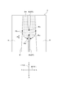
- FIG. 1 is a perspective view showing a configuration example of a welding apparatus 7 according to an embodiment of the present invention.
- FIG. 2 is a diagram showing a captured image V according to an embodiment of the present invention.
- the welding device 7 is a device for automatically arc-welding a welding object such as a steel plate. As shown in FIG. 1, the welding device 7 includes a welding control device 1 that controls welding work, and a welding execution device 8 that executes arc welding in accordance with control (command) from the welding control device 1.
- the welding execution device 8 constituting the welding device 7 will be described.
- the welding execution device 8 includes a wire feed mechanism 81, an electrode 82, and an imaging unit 83.
- the wire feeding mechanism 81 is a mechanism for sequentially feeding (supplying) the welding wire 8 w that is consumed along with the welding work toward the welding location of the welding object 9.
- the tip portion of the welding wire 8w set in the wire feed mechanism 81 is melted by arc discharge from the electrode 82, so that the liquid phase metal in which the welding wire 8w is melted is welded to the welded object 9 (weld
- the welding object 9 is welded by being cooled and solidified in (Part).
- the welding portion of the welding object 9 is a gap formed between two members extending in the horizontal direction, and the wire feed mechanism 81 and the electrode 82 are the length of the gap of the welding object 9.
- Welding is performed by relative movement along the direction. More specifically, the molten metal is a liquid phase metal in which the welding wire 8w is melted by the relative movement of the wire feed mechanism 81 and the electrode 82 at a predetermined welding speed along the longitudinal direction of the gap between the welding objects 9. 8 m are sequentially formed along the welding direction (longitudinal direction of the gap) (see FIG. 2). And the welding object 9 is welded because the molten pool 8m cools and solidifies.
- the front-rear direction of the welding direction is the front-rear direction
- the width direction of the gap of the welding object 9 (the direction orthogonal to the longitudinal direction) is the left-right direction
- the direction orthogonal to the front-rear direction and the left-right direction is the vertical direction. (Vertical direction in FIG. 1).
- at least a part of a member that supports the electrode 82 including the electrode 82 is positioned directly above the welding wire 8w, and the tip of the welding wire 8w and the electrode 82 are shown in FIG. The position is closer than shown.
- the photographing unit 83 is a photographing device such as a camera for photographing a moving image or a still image, and is installed so as to photograph a welding part.
- a photographed image V (hereinafter simply referred to as a photographed image V) of a welded portion photographed by the photographing unit 83 is a wall surface that forms a gap between the above-described welding wire 8w, the molten pool 8m, the electrode 82, and the welding object 9. This is used to detect the positions of at least two photographing objects in the groove 91.
- the photographing unit 83 is installed at a position to look into the welded portion obliquely from above in order to photograph the above-described photographing object in the same image.
- the imaging unit 83 is configured so that the captured image V includes a welding wire 8 w, an electrode 82, a molten pool 8 m, and a groove 91 as shown in FIG. 2. It is comprised so that a welding location may be image
- the welding execution apparatus 8 and the welding object 9 move relative to each other, but are installed in the welding execution apparatus 8.
- the position of the groove 91 in the captured image V changes according to the shape of the welding object 9.
- the welding wire 8w is supplied to the welding location while being drawn out of the reel wound by using the wire feed mechanism 81.
- the welding wire 8w in the photographed image V may be bent due to bending of the welding wire 8w.
- the position of 8w also changes. Therefore, the welding execution device 8 has a mechanism for moving (adjusting) the positions of the welding wire 8w and the electrode 82.
- the welding wire 8 w and the electrode 82 can be moved in the front-rear direction and the left-right direction in the captured image V, respectively.
- the welding wire 8w and the electrode 82 as described above are used as the position control object 8T, and the position of the position control object 8T is moved in accordance with a command from the welding control device 1.
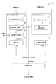
- FIG. 3A is a block diagram showing the function of the welding control apparatus 1 according to one embodiment of the present invention, and determines the target relative position Rt with the welding condition C as an input.
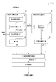
- FIG. 3B is a block diagram showing the function of the welding control apparatus 1 according to one embodiment of the present invention, and determines the target relative position Rt with the molten pool position Pm and the wire position Pw as inputs.
- the welding control apparatus 1 is an apparatus configured to control the position of a position control object 8T including at least one of a welding wire 8w used for welding the welding object 9 or an electrode 82 for melting the welding wire 8w. It is.
- the welding control apparatus 1 is a welding feature amount P detected from a photographed image V photographed so as to include at least the position control object 8T, and at least one of the wire position Pw of the welding wire 8w or the electrode position Pe of the electrode 82.
- the actual position determination unit that determines (acquires) the actual position of the position control object 8T based on the welding feature amount P included, and the target of the actual position according to the welding condition C when welding the welding object 9.
- a target position determining unit that determines the target position; and a position control unit that executes position control of the position control target 8T for setting the actual position to the target position.
- the actual position of the position control object 8T is an actual position detected from the captured image V, and may be, for example, a position (absolute position) in the coordinate system set for the captured image V. Even if the wire position Pw and the electrode position Pe, which are the positions of the controlled object 8T, are relative positions (actual relative positions Rr) from other welding feature amounts P (a molten pool position Pm, a groove position Pb, etc. described later). good.
- the absolute position such as the wire position Pw is set to the center in the left-right direction (described later) of the captured image V in a state where, for example, a camera that captures the captured image V is fixed. Is controlled as a target position.
- a function capable of calculating the target absolute position corresponding to the target position from the absolute position or other welding feature amount P is prepared in advance, and the target absolute position is calculated from the welding feature amount P using such a function. You may ask for. More specifically, for example, the target absolute position is obtained from a position in the left-right direction (described later) of the electrode position Pe and the groove position Pb by using a nonlinear function or a table.
- the welding control apparatus 1 includes an actual relative position determination unit 2, a target relative position determination unit 3, and a position control unit 5.
- the embodiment in which the actual position of the position control target 8T is an absolute position may be considered by replacing the actual relative position Rr in the following description with the absolute position and the target relative position Rt with the target absolute position.
- the welding control device 1 is configured by a computer and includes a CPU (processor) (not shown), a memory such as a ROM and a RAM, and a storage device m such as an external storage device. And each said function part with which the welding control apparatus 1 is provided is implement
- the welding control program 10 described above is software for causing a computer to realize each functional unit described later, and may be stored in a storage medium that can be read by the computer.
- the actual relative position determination unit 2 is the welding feature amount P detected from the above-described captured image V, and includes the groove position Pb of the groove 91, the wire position Pw of the welding wire 8w, and the molten pool position Pm of the molten pool 8m. Or an actual relative position Rr that is a relative position of any two of the welding feature amounts P including at least two of the electrode positions Pe of the electrode 82 is determined.
- the photographed image V is photographed so as to include at least one of the molten pool 8m or the groove 91 formed in the groove 91 of the welding object 9 by melting the position control object 8T and the welding wire 8w.
- the captured image V includes at least a portion of the welding wire 8w at the wire position Pw and at least a portion of the molten pool 8m at the molten pool position Pm, or
- the groove 91 includes at least the groove position Pb.
- the captured image V includes at least the electrode position Pe portion of the electrode 82 and at least the groove position Pb portion of the groove 91.
- the wire position Pw is a position of a desired portion in the welding wire 8w.
- the molten pool position Pm is a desired part in the molten pool 8m.
- the groove position Pb is a position of a desired part in the groove 91.
- the electrode position Pe is a position of a desired part in the electrode 82.
- the wire position Pw is the position of the distal end portion of the welding wire 8w located at the rearmost side (the lowest side in the vertical direction) of the photographed image V. Yes.
- the molten pool position Pm is the position of the tip of the molten pool 8m located on the most front side in the captured image V.
- the groove position Pb is a predetermined position determined by a position relative to the electrode 82.
- the electrode position Pe is the tip of the electrode 82 located at the rearmost side (the lowest side in the vertical direction) of the captured image V.
- the welding feature amount P includes at least the wire position Pw and the molten pool position Pm.
- the actual relative position determination unit 2 detects the welding feature amount P by performing image processing on the captured image V, and calculates the actual relative position Rr based on the detection result.
- the position control object 8T is the welding wire 8w
- the wire position Pw and the molten pool position Pm are detected in order to perform position control in the vertical direction.
- the wire position Pw and the groove position Pb are detected in order to perform position control in the left-right direction.
- the position control object 8T is the electrode 82
- the electrode position Pe and the groove position Pb are detected in order to perform position control in the left-right direction.
- the actual relative position Rr may be a distance along the direction in which the controlled object is controlled.
- the position (coordinates) based on an arbitrary position such as the lower left end of the captured image V, or the other position (coordinates) based on one of the two welding feature amounts P constituting the actual relative position Rr. ).
- the position control object 8T is at least a welding wire 8w
- the welding feature amount P includes a wire position Pw and a molten pool position Pm.
- the actual relative position determination unit 2 includes a captured image acquisition unit 21 that acquires a captured image V from a capturing unit 83 that captures a welding location during welding, and a predetermined control cycle T.
- a welding feature amount detection unit 22 that detects the welding feature amount P including the wire position Pw and the molten pool position Pm from the photographed image V (one or more) obtained by the photographed image acquisition unit 21 is detected every time.
- a calculation unit 24 that calculates an actual relative position Rr (wire pool relative position) based on the wire position Pw and the weld pool position Pm welding feature amount P.
- the photographed image acquisition unit 21 is connected to the photographing unit 83 so that the photographed images V are sequentially input (in real time).
- the welding feature amount detection unit 22 is connected to the captured image acquisition unit 21 so that the captured images V acquired by the captured image acquisition unit 21 are sequentially input.
- the captured image acquisition unit 21 may store all of the input captured images V in the storage device m, or store a part of them in the storage device m by thinning out at a predetermined interval or the like. May be.
- the captured image V stored by the captured image acquisition unit 21 is input to the welding feature amount detection unit 22.
- the welding feature-value detection part 22 detects the welding feature-value P for every predetermined control period T.
- the calculation unit 24 is connected to the welding feature amount detection unit 22 so that the welding feature amount P is sequentially input. Accordingly, the actual relative position Rr can be sequentially calculated by sequentially performing image processing on the captured image V at the time of welding.
- the target relative position determination unit 3 determines a target relative position Rt that is a target of the above-described relative position (actual relative position Rr such as a wire pond relative position) according to the welding condition C when welding the welding object 9. .
- the welding condition C is a condition that affects the welding state of the welding object 9 by the welding execution device 8.
- the welding condition C includes an electrode current and an electrode voltage with respect to the electrode 82, a welding speed which is a relative movement speed (arc movement speed) between the welding execution device 8 and the welding object 9, and a supply amount (unit) of the welding wire 8w. Supply amount per hour) and at least one condition of the groove width of the groove 91 may be included.
- ⁇ ⁇ Welding state varies depending on the heat input condition during welding, but welding condition C sets the heat input condition. Specifically, the greater the electrode current and electrode voltage, the greater the heat input. As the welding speed increases, the number of locations to be welded per unit time increases, so the amount of heat input per unit amount of the size of the weld location decreases. The greater the supply amount of the welding wire 8w, the smaller the heat input per unit amount of the welding wire 8w. Moreover, since the weld pool 8m spreads in the left-right direction and the like as the groove width increases, the amount of heat input per unit volume decreases.
- the target relative position Rt needs to be able to be compared with the above-described actual relative position Rr.
- the other position based on one of the feature amounts P may be used.
- machine learning may be applied to determine the target relative position Rt.
- the position control unit 5 controls the position of the welding object so that the actual relative position Rr determined by the actual relative position determination unit 2 described above becomes the target relative position Rt determined by the target relative position determination unit 3 described above.
- the position control of the welding target object is a control amount of the welding target object required to make the difference (deviation amount) between the actual relative position Rr and the target relative position Rt fall within a predetermined range including zero.
- the calculated control amount is transmitted to the welding execution device 8.
- the welding execution apparatus 8 controls the position of a welding target object according to the received control amount.
- control amount may be a movement amount in a direction from which the current position is to be moved, or the coordinates to which the welding object is to be moved in the coordinate system in which the welding execution device 8 recognizes the position. It may be. Further, the position control unit 5 may control the position of the welding object while detecting the moved position that has moved relative to the transmitted control amount through image processing of the captured image V (feedback control).
- the relative position (wire pool relative position) along the front-rear direction between the wire position Pw and the molten pool position Pm has been described as an example.
- the present invention is not limited to this embodiment.
- position control according to the welding condition C similar to that described above may be performed.
- the electrode position Pe and the wire position Pw of the electrode 82 are detected from the photographed image V, and the target relative position is calculated based on the welding condition C.
- the electrode 82 and the wire position Pw may be controlled in the front-rear direction so that the actual relative position between the electrode position Pe and the wire position Pw becomes the target relative position.
- the electrode position Pe and the groove position Pb of the groove 91 are detected from the photographed image V, and the target relative position is calculated based on the welding condition C.
- the electrode position Pe may be controlled in the left-right direction so that the actual relative position with respect to the previous position Pb becomes the target relative position.
- the electrode position Pe may be the front end portion of the electrode 82 located on the most front side in the front-rear direction
- the groove position Pb is a predetermined position determined by a relative position with respect to the electrode 82. It may be a position.
- the target (target relative position) of any two relative positions contained in welding feature-values such as the relative position of the position of the welding wire 8w and the position of the molten pool 8m, for example. Rt) is determined.
- control with respect to the welding execution apparatus 8 is performed so that the actual relative position (actual relative position Rr) obtained through the image processing of the photographed image V for the welding state by the welding execution apparatus 8 becomes a target.
- arc welding with a welding quality equivalent to that performed by a welder can be automatically performed, and automatic welding with reduced dependence on the welder skill can be realized.
- the actual relative position Rr and the target relative position Rt will be described as an example of the relative position between the wire position Pw and the molten pool position Pm in order to provide a more specific description.
- the present invention is not limited to this, and any two relative positions of the above-described welding feature amount P (wire position Pw, molten pool position Pm, electrode position Pe, groove position Pb) may be used.
- the wire position Pw and the molten pool position Pm in the description may be read as two desired positions and applied.
- the target relative position determination unit 3 described above includes a welding condition acquisition unit 31 that acquires a welding condition C when performing welding on the welding object 9, and Relative position of welding conditions (past welding conditions) at the time of welding performed in the past, past molten pool position (past molten pool position) and past wire position (past wire position) set under this past welding condition From the welding condition C acquired by the welding condition acquisition unit 31 based on the relationship with the past relative position that is any two relative positions of the above-described welding feature amount P, the target corresponding to the welding condition A condition-based target determination unit 32 that determines the relative position Rt.
- condition-based target determination unit obtains a learning model obtained by machine learning a plurality of data in which the past welding conditions are associated with the past relative positions set under the past welding conditions.
- (Condition-based learning model) is used to determine the target relative position according to the welding conditions, the place, the weld pool position Pm and the wire position Pw, etc.
- the information set of the past relative position calculated based on the welding feature amount P and the welding condition C is acquired a plurality of times at different times, for example.
- the plurality of data obtained by associating the past relative positions at each of the plurality of timings and the welding condition C are used as learning data.
- a known method such as a neural network or regression analysis may be applied to the learning of the learning data.
- the learning model and the regression equation (hereinafter, learning model) obtained in this way are derived from the relationship between the welding condition C performed by the welder and the above-mentioned past relative position. For this reason, by using the learning model, it is possible to obtain the target relative position Rt such as the wire pond relative position that the welder will set for the welding condition C to be input. Therefore, the target relative position determination unit 3 can determine the target relative position Rt corresponding to the acquired welding condition C by using the learning model.
- the target relative position determination unit 3 determines the target relative position Rt according to the welding condition C including such an aggregation condition. For example, the relationship between the welding condition C including the three conditions of the welding speed, the welding current, and the welding voltage in one condition of the amount of heat input and the past relative position may be learned.
- the learning model in this case includes one condition of heat input instead of the three conditions of welding speed, welding current, and welding speed.
- the present invention is not limited to this embodiment.
- the conditions that best represent the relationship with the target relative position Rt may be collected according to the situation. For example, in some other embodiments, two conditions of welding speed and welding current may be combined into one condition of heat input.
- the welding condition C when welding the welding object 9 may be acquired from the welding execution device 8 as a set value set in the welding execution device 8 or the like, or input from an operator or the like. You may get it.
- any of the welding feature amounts P such as the relative position between the welding wire 8w and the molten pool 8m obtained as a result of the welder operating the position control target 8T such as the welding wire 8w, for example.
- the target relative position Rt is obtained directly from the welding conditions C based on the learning results. .
- the target relative position Rt can be appropriately determined. Further, by using the target relative position Rt thus determined for position control, it is possible to realize a welding quality equivalent to that performed by a welder.
- the target relative position determination unit 3 may perform past welding characteristics such as past weld pool positions and past wire positions during welding performed under past welding conditions performed during past welding. Based on the relationship between the amount (hereinafter referred to as past welding feature amount) and the past relative position, which is the relative position of the past welding feature amount, from the welding feature amount P such as the weld pool position Pm and the wire position Pw as input, A position-based target determination unit 34 that determines a target relative position Rt according to the welding condition C is provided.
- past welding feature amount the amount
- the past relative position which is the relative position of the past welding feature amount
- the heat input condition (heat input state) at the time of welding changes, so that the position of the position control object 8T such as an appropriate welding wire 8w or electrode changes according to the welding condition C.
- the welder's operation is based on the welding feature amount P (wire position Pw, molten pool position Pm, electrode position Pe, open position) for ensuring the welding quality mainly based on visual information of different welding states depending on the welding condition C. High-quality welding is achieved by recognizing the tip position Pb and the like and manipulating the wire position Pw and the electrode 82 based on experience. Under such knowledge, the operation performed by the welder reflects the difference in the welding condition C, and instead of the welding condition C, the target relative position Rt can be obtained from the operation history of the welder. It was.
- the target relative position determination unit 3 is a learning model (position-based learning model) obtained by machine learning a plurality of data in which the above-described past welding feature amount and the above-described past relative position are associated with each other. ) Is used to determine the target relative position Rt according to the welding condition C from the welding feature amount P. That is, for each welding operation in which the time, place, and welding object 9 are different, the information set of the welding feature amount P such as the molten pool position Pm and the wire position Pw at the same timing is acquired a plurality of times at different times, for example.
- the welding feature amount P such as the molten pool position Pm and the wire position Pw at the same timing is acquired a plurality of times at different times, for example.
- the molten pool position Pm, the wire position Pw, and the data of the relative position calculated values at the same timing can be obtained at a plurality of timings, and the plurality of data can be learned.
- Data A known learning method as described above may be applied to learning of this learning data.
- the learning model obtained by learning is obtained by deriving the relationship between, for example, the molten pool position Pm and the wire position Pw performed by the welder and the calculation result of the relative positions of the two. For this reason, by using the learning model, it is possible to obtain the wire pond relative position and the like that the welder will set for the welding feature amount P to be input. Therefore, the target relative position determination unit 3 can determine the target relative position Rt corresponding to the welding feature amount P by using the learning model.
- the target relative position Rt is obtained from the welding feature amount P such as the position of the molten pool 8m and the position of the welding wire 8w.
- the target relative position Rt between the welding wire 8w and the weld pool 8m is in a linear relationship from a large amount of data (learning data), it has not been experienced yet, but it has been experienced in the past. Since the welding condition C close to the above condition and the condition located in the interpolation of a plurality of data are within the category of linear modeling, they can be handled. Further, by using the target relative position Rt thus determined for position control, it is possible to realize a welding quality equivalent to that performed by a welder.
- the target relative position Rt corresponding to the welding condition C is created in advance by creating target value conversion means such as a function or a table that is set in consideration of the heat input condition and the like.
- the determination unit 3 may determine the target relative position Rt from the welding condition C using the target value conversion means.
- the target relative position determination unit 3 uses target value conversion means for obtaining a target relative position Rt corresponding to the welding condition C from the welding condition C created using the condition-based learning model described above. May be used to determine the target relative position Rt from the welding condition C.
- the target relative position determination unit 3 includes target value conversion means for obtaining the target relative position Rt corresponding to the welding feature amount P from the welding feature amount P created using the position-based learning model described above. It may be used to determine the target relative position Rt from the welding feature amount P.
- the target relative position Rt according to the welding condition C can be calculated while suppressing the calculation amount.
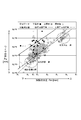
- FIG. 6 is a graph showing the relationship between the weld pool position Pm, the wire position Pw, and the operation history by the welder according to an embodiment of the present invention.
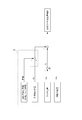
- FIG. 7 is a diagram showing logic when a welding failure event according to an embodiment of the present invention is detected.
- the welding control apparatus 1 performs the position control of the position control target 8T based on the difference between the target relative position Rt and the actual relative position Rr. You may further provide the position control necessity determination part 4 which determines NO.
- the position control unit 5 described above performs position control of the position control target 8T such as the welding wire 8w according to the determination result by the position control necessity determination unit 4.
- the horizontal axis is the molten pool position Pm
- the vertical axis is the wire position Pw
- the operation content of the welder is plotted against the molten pool position Pm and the wire position Pw.
- FIG. 6 shows how the welder has performed each combination of the molten pool position Pm and the wire position Pw. Specifically, the welder operates downwards at points plotted with black squares (down operation), operates upwards at points plotted with light colored squares (up operation), and plots with white circles. Indicates that no operation was performed. Note that the molten pool position Pm and the wire position Pw in the graph shown in FIG. 6 are relative to the origin at the lower left end of the captured image V (see FIG. 2). Is not limited, and the origin of coordinates may be any position.
- the value on the vertical axis in FIG. 6 is larger by a constant S than the value on the horizontal axis, and the broken line is a line connecting points where the wire position Pw is larger by the constant S than the molten pool position Pm.
- the broken line it can be seen that, for example, the positions of the weld pool position Pm and the wire position Pw differ depending on whether the welding speed is fast or slow. Also, regarding the wire pond relative position (distance), when the welding speed is high, the wire position Pw of the plot point (white circle) without operation is concentrated below the broken line, and the actual relative position Rr is more It is getting shorter.
- the welder may or may not operate while the wire position Pw takes various values at an arbitrary weld pool position Pm such as when the weld pool position Pm is ax. Then, from FIG. 6, the welder does not operate in a certain range of the wire position Pw at the molten pool position Pm, and performs a lower operation when the wire position Pw becomes larger beyond that range, and the wire position Pw is within that range. Below this, there is a tendency to perform the above operation.
- the welder finds that the difference (
- the predetermined range includes the past weld pool position at the time of welding performed in the past, the past wire position, and whether or not the past wire position has been operated at that time. May be determined based on a plurality of operation history data in which past welding feature amounts and the corresponding operation presence / absence of the position control target 8T are associated with each other.
- the position control necessity determination unit 4 determines the welding wire when the difference between the actual relative position Rr and the target relative position Rt deviates from the control dead zone (predetermined range) determined as described above. It is determined that position control of the position control target 8T such as 8w is necessary. Conversely, the position control necessity determination unit 4 determines that the position control of the position control target 8T is unnecessary when the above difference is within the range of the control dead zone.
- a classification model in which a welding feature amount P is input and an operation presence / absence label is output is generated by a support vector machine (SVM), and a feature space to be noted (in FIG. 6, a molten pool)
- SVM support vector machine
- a feature space to be noted in FIG. 6, a molten pool
- label operation present
- label no operation
- the line thus obtained is a line indicated by a solid line and a two-dot chain line shown in FIG.
- the solid line is a separation boundary between the presence and absence of the lower operation, the space above the solid line is the lower operation, and the lower space is the lower operation.
- the alternate long and two short dashes line is a separation boundary between the presence and absence of the upper operation, the space above the solid line is the upper operation, and the lower space is the lower operation.
- the space between the two separation boundaries becomes a control dead zone that does not require any operation.
- the lower operation is executed when the wire position Pw with respect to the molten pool position Pm becomes larger than the solid line
- the upper operation is executed when the wire position Pw becomes smaller than the two-dot chain line. If it is between the dotted lines, no operation is performed.
- the range between the solid line and the two-dot chain line at each weld pool position Pm is the control dead zone, and this control dead zone is set as the control target range of the wire position Pw. Note that the target relative position Rt calculated by the target relative position determination unit 3 falls within this control target range.
- the position control necessity determination unit 4 is connected to the actual relative position determination unit 2 and the target relative position determination unit 3, respectively, and the actual relative position Rr and the target relative position Rt. Is input, and the actual relative position Rr and the target relative position Rt are input from the actual relative position determination unit 2. Further, when the actual relative position Rr and the target relative position Rt are input, the position control necessity determination unit 4 determines that the target relative position is different if the difference between the actual relative position Rr and the target relative position Rt is within the range of the control dead zone. Even if there is a difference between the position Rt and the actual relative position Rr, the position control of the wire position Pw is not performed. On the contrary, if the difference between the actual relative position Rr and the target relative position Rt deviates from the range of the control dead zone, the position control of the wire position Pw is performed so that it falls within the range of the control dead zone.
- the collected operation history data (learning data) has little operation with respect to no operation (eg, with lower operation, with upper operation), and when the number of data is biased in this way, the SVM identification performance Is known to decrease significantly. Therefore, in order to eliminate the data number imbalance, the embodiment shown in FIG. 6 has a problem that the class with operation with a small number of data is underestimated by weighting the class based on the data number ratio. It has been resolved.
- the range for determining the necessity of execution of the position control of the welding wire 8w is made into the presence or absence of operation of the position of the welding wire 8w which the welder performed, the past molten pool position, and a wire position. Make a decision based on the relationship. Accordingly, the predetermined range can be appropriately set, and welding equivalent to that of a welder can be automatically performed with a small number of operations.
- the predetermined range may be determined according to the welding condition C.
- the control dead zone for determining whether or not the position control of the welding wire 8w needs to be performed is the welding characteristic amount P such as the weld pool position Pm and the wire position Pw in which the welding condition C or the welding condition C is reflected.
- the predetermined range (the range of the control dead zone) can be set according to the welding condition C, and the welding condition C and the position of the welding feature amount P such as the welding wire 8w need to be strictly controlled.
- the welding conditions C that are not so can be appropriately handled.
- the welding condition C may be constant regardless of the welding condition C.
- the actual relative position determination unit 2 described above detects abnormalities in the welding feature amount P detected by the welding feature amount detection unit 22 every control cycle T as shown in FIGS. 3A to 3B. You may further have the detection abnormality determination part 23 which determines (henceforth simply detection abnormality). More specifically, the actual relative position determination unit 2 captures images acquired in the normal control cycle Ts in the normal control cycle Ts that is the control cycle T determined by the detection abnormality determination unit 23 that no detection abnormality has occurred. The actual relative position Rr is calculated based on the welding feature amount P detected from the image V.
- this abnormality control cycle Tf in the abnormality control cycle Tf that is the control cycle T determined that the detection abnormality has occurred by the detection abnormality determination unit 23, this abnormality control cycle Tf.
- the actual relative position Rr may be calculated based on the welding feature amount P detected from the captured image V acquired in the normal control cycle Ts that has already ended before. That is, the actual relative position determination unit 2 may use the actual relative position Rr obtained in the normal control cycle Ts before the abnormal control cycle Tf in the abnormal control cycle Tf.
- the above-described detection abnormality is caused when the welding feature amount P cannot be detected from the photographed image V at every control cycle T by the image processing by the welding feature amount detection unit 22 or when the value of the welding feature amount P has been set so far.
- This is a case where the value greatly changes from the value unexpectedly, or a case where the value of the welding feature amount P becomes an outlier, such as a case where the value is not normally possible.
- the amount of heat input determined by the welding condition C is too small, the captured image V becomes too dark.
- the amount of heat input is too large, the captured image V becomes too bright.
- the welding feature amount P cannot be detected properly, for example, because the welding feature amount P cannot be detected or is detected by mistake.
- the actual relative position Rr obtained from the photographed image V acquired in the normal control cycle Ts prior to this determination is not immediately stopped. By using it, welding is continued. This is because the detection abnormality of the welding feature amount P may temporarily occur according to the amount of heat input at the time of welding or the like, and may recover naturally.
- the welding feature amount P detected from the captured image V acquired in the previous normal control cycle Ts may be input to the calculation unit 24.
- the actual relative position Rr from the captured image V acquired in the previous normal control cycle Ts may be output from the calculation unit 24.
- the detection abnormality determination unit 23 is based on a notification that the welding feature amount P input from the welding feature amount detection unit 22 cannot be detected or the value of the welding feature amount P. The presence or absence of detection abnormality is determined.
- the detection abnormality determination unit 23 determines that there is no detection abnormality, the detection abnormality determination unit 23 outputs the welding feature amount P input from the welding feature amount detection unit 22 to the calculation unit 24.
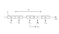
- FIG. 4 is a diagram for explaining the operation at the abnormal control cycle Tf of the actual relative position determination unit 2 according to the embodiment of the present invention, and the normal control cycle before the predetermined period R at the abnormal control cycle Tf. The case where Ts exists is shown.
- each control cycle T is repeated with the passage of time, and a welding feature amount P (P1, P2,..., Pn ⁇ 1) is obtained from the captured image V acquired in each control cycle T.
- Pn + 1..., N is an integer).
- the actual relative position determination unit 2 (welding feature amount detection unit 22) cannot detect the welding feature amount P from the captured image V acquired in the nth control cycle T (abnormal control cycle Tf). Therefore, the actual relative position determination unit 2 uses the welding feature amount P detected from the captured image V of the normal control cycle Ts before (previous) the n-th abnormal control cycle Tf as the n-th abnormal control cycle Tf. The welding feature amount P detected from the photographed image V is used instead.
- the actual relative position is determined when there is no normal control cycle Ts within a period preceding the predetermined control period R determined according to the welding feature amount P from the abnormal control cycle Tf.
- the unit 2 may be configured not to determine the actual relative position Rr in the abnormal control cycle Tf. In other words, notification may be made when the period from the abnormal control period Tf to the first normal control period Ts exceeds the predetermined period R. Or you may perform the notification mentioned later from the detection abnormality determination part 23.
- the welding feature amount P in the (n-2) th normal control cycle Ts may be substituted.
- the welding feature amount P in the (n ⁇ 1) th (immediately preceding) normal control cycle Ts is substituted, but if the welding feature amount P is in the normal control cycle Ts included in the predetermined period R, the welding feature amount P is used. good.
- a plurality of captured images V are captured by the captured image acquisition unit 21 during one control period T in which the above-described welding feature amount detection unit 22 detects the welding feature amount P. Acquired and stored in the storage device m or the like. And the welding feature-value detection part 22 detects the welding feature-value P from the some picked-up image V accumulate
- a plurality of values are detected from a plurality of captured images V with respect to one position such as the wire position Pw in the normal control cycle Ts, it is considered most appropriate as a control reference.
- a value detected from the latest captured image V within one period of the normal control period Ts among the captured images V whose positions are appropriately detected is used as a welding feature amount P for subsequent calculation of the actual relative position Rr. It may be used.
- one captured image is captured by the captured image acquisition unit 21 during one period of the control period T described above. V may be acquired.
- the welding feature amount detection unit 22 determines that the detection abnormality has been determined when the target welding feature amount P cannot be detected from one captured image V obtained every control cycle T. .
- the welding feature amount P when the welding feature amount P is not properly detected from the photographed image V, for example, the welding feature amount P detected from the photographed image V acquired in the normal control cycle Ts such as immediately before.
- the actual relative position Rr based on the captured image V that has been determined not to have a detection abnormality is used, for example, by calculating the actual relative position Rr using (alternative feature amount).
- welding can be performed continuously.
- the actual relative position determination unit 2 does not control the position control target 8T by not outputting the actual relative position Rr to the calculation unit 24 in the abnormality control cycle Tf. You may do it.
- the detection abnormality determination unit 23 performs the operation after the abnormality control cycle Tf to the first normal control cycle Ts. Is notified when the predetermined period R exceeds a predetermined period R determined according to the position control object 8T such as the welding wire 8w (see FIG. 5). That is, when the detection abnormality of the welding feature amount P from the photographed image V continues beyond the predetermined period R, notification is made assuming that it is necessary to determine whether welding can be continued. This notification notifies the detection abnormality of the welding feature amount P.
- the detection abnormality determination unit 23 may automatically transmit a command for stopping the welding to the welding execution device 8 together with this notification.
- FIG. 5 is a diagram for explaining the operation at the abnormal control cycle Tf of the actual relative position determination unit 2 according to the embodiment of the present invention, and the normal control cycle before the predetermined period R at the abnormal control cycle Tf.
- Ts does not exist
- the Pn ⁇ 1th control cycle T is the normal control cycle Ts
- Pnth to Pn + m ⁇ 1th is the abnormal control cycle Tf.
- the actual relative position determination unit 2 welding feature amount detection unit 22
- the detection abnormality determination unit 23 performs the above notification after the time point when the (n + m ⁇ 1) th control cycle T ends. Further, a command to stop the above-described welding may be transmitted together with this notification.
- the welding feature amount P in the previous normal control cycle Ts may be substituted as described above.
- the predetermined period R is a period in which welding can be continued without control even when the welding feature amount P changes. Notification will be made after the elapse. Thereby, it is possible to improve the reliability of welding while continuing welding as much as possible.
- the electrode 82 has a relatively long period during which welding can be expected without control.
- the welding wire 8w is used while being pulled out on the reel, the position of the welding wire 8w may suddenly change, and the position changes from the position of the captured image V immediately before the detection abnormality. It is easy and the period in which welding can be continued without control is relatively short.
- the predetermined period R according to the welding feature amount P, it is possible to continue welding suitable for abnormal detection of various feature amounts included in the welding feature amount P.
- the welding control apparatus 1 detects the target relative position determined by the target relative position determination unit 3 when it detects a welding failure event. You may further provide the target position correction
- the target position correction unit 6 detects a welding failure event before the target relative position Rt output from the target relative position determination unit 3 is input to the position control necessity determination unit 4.
- the correction amount to be output to is for correcting the target relative position Rt.
- the corrected target relative position Rt ′ and the actual relative position Rr are input to the position control necessity determining unit 4.
- the above-described welding failure phenomenon may be caused by, for example, a droplet generated when the tip of the welding wire 8w is not in the molten pool 8m or a welding target 9 in which the tip of the welding wire 8w is the bottom of the molten pool 8m. It is an event such as a crushing collision.
- the tip of the droplet floats upward due to a warp or the like of the welding wire 8w, and falls into the molten pool 8m when the tip of the welding wire 8w is melted by arc heat in a state where it is not inserted into the molten pool 8m. It is a liquid phase ball-shaped metal in which the welding wire 8w is melted.
- the welding wire 8w may not be melted and may collide with the electrode 82.
- the electrode 82 and the welding wire 8w may be short-circuited to interrupt the arc discharge, or the electrode 82 may be damaged.
- the position control of the welding wire 8w at the time of detecting such a welding failure event and the position control of the welding wire 8w for making the actual relative position Rr the target relative position Rt are separately performed.
- control hunting may occur as a result of trying to control in opposite directions, such as one trying to control downward and the other trying to control upward.
- the occurrence of hunting as described above can be avoided by correcting the target relative position Rt on the basis of a welding failure event.
- FIG. 8 is a diagram illustrating a welding control method according to an embodiment of the present invention.
- the welding control method is a method of controlling the position of the position control object 8T including at least one of the welding wire 8w used for welding the welding object 9 or the electrode 82 for melting the welding wire 8w.
- the welding control method includes an actual relative position determination step (S1) (actual position determination step), a target relative position determination step (S2) (target position determination step), and a position control step (S4). And comprising.
- the welding control method may include a position control necessity determination step (S3).
- the welding control method will be described in the order of steps with reference to FIG.
- the flow of FIG. 8 is repeatedly performed at the time of welding construction, for example periodically.
- step S1 in FIG. 8 an actual relative position determination step is executed.
- the actual relative position determination step (S1) is a step of determining the actual relative position Rr described above based on the captured image V. Since the actual relative position determination step (S1) is the same as the processing contents executed by the actual relative position determination unit 2 described above, the details are omitted.
- step S11 a captured image V is acquired from the above-described imaging unit 83 (captured image acquisition step), and in step S12, the above-described welding feature amount P is detected from the captured image V (welding).
- step S13 the actual relative position Rr is calculated based on the welding feature amount P (calculation step).
- some embodiments may further include a detection abnormality determination unit step (not shown) for determining a detection abnormality of the welding feature amount P in the welding feature amount detection step (step S12). . Since the detection abnormality determination unit step is the same as the processing content executed by the detection abnormality determination unit 23 already described, the details are omitted.
- step S2 a target relative position determination step is executed.
- the target relative position determining step (S2) is a step for determining the target relative position Rt described above. Since the target relative position determination step (S2) is the same as the processing contents executed by the target relative position determination unit 3 already described, the details are omitted, but in some embodiments, the above-described machine learning is used.
- the target relative position Rt may be determined by a technique.
- step S3 a position control necessity determination step is executed.
- the position control necessity determination step (S3) is a step for determining whether or not the position control of the position control target 8T is necessary based on the difference between the target relative position Rt and the actual relative position Rr. Since the position control necessity determination step (S3) is the same as the processing contents executed by the position control necessity determination unit 4 already described, the details are omitted.
- step S31 when it is determined in step S31 whether the difference between the target relative position Rt and the actual relative position Rr has deviated from the control dead zone described above, Then, it is determined that the position control of the position control object 8T is necessary, and the process proceeds to the next step S4.
- step S31 when it is determined in step S31 that the difference between the target relative position Rt and the actual relative position Rr does not deviate from the control dead zone, it is determined that position control of the position control target 8T is not necessary, and the flow ends. To do.
- step S4 a position control step is executed.
- the position control step (S4) the actual relative position Rr determined in the actual relative position determination step (S1) described above is changed to the target relative position Rt determined in the target relative position determination step (S2).
- This is a step of performing position control of the position control object 8T. Since the position control step (S4) is the same as the processing content executed by the position control unit 5 already described, the details are omitted.
- the above welding control method includes a target position correction step for correcting the target relative position Rt determined by the target relative position determination step (S2) when a welding failure event is detected. Further, it may be provided. Since the target position correction step is the same as the processing contents executed by the target position correction unit 6 already described, the details are omitted.
- the target relative position determination step (S2) may be performed between step S2 and step S3 in FIG. 8 (see FIG. 7).
- the present invention is not limited to the above-described embodiments, and includes forms obtained by modifying the above-described embodiments and forms obtained by appropriately combining these forms.
Landscapes
- Engineering & Computer Science (AREA)
- Physics & Mathematics (AREA)
- Mechanical Engineering (AREA)
- Plasma & Fusion (AREA)
- Artificial Intelligence (AREA)
- Automation & Control Theory (AREA)
- General Physics & Mathematics (AREA)
- Evolutionary Computation (AREA)
- Medical Informatics (AREA)
- Software Systems (AREA)
- Computer Vision & Pattern Recognition (AREA)
- Health & Medical Sciences (AREA)
- Human Computer Interaction (AREA)
- Manufacturing & Machinery (AREA)
- Arc Welding In General (AREA)
- Arc Welding Control (AREA)
- Lining Or Joining Of Plastics Or The Like (AREA)
- Image Processing (AREA)
Priority Applications (4)
| Application Number | Priority Date | Filing Date | Title |
|---|---|---|---|
| ES19791734T ES2969093T3 (es) | 2018-04-25 | 2019-03-25 | Dispositivo de control de soldadura, procedimiento de control de soldadura y programa de control de soldadura |
| US17/040,612 US11958143B2 (en) | 2018-04-25 | 2019-03-25 | Welding control device, welding control method, and welding control program |
| KR1020207023990A KR102314414B1 (ko) | 2018-04-25 | 2019-03-25 | 용접 제어 장치, 용접 제어 방법 및 용접 제어 프로그램 |
| EP19791734.7A EP3753663B1 (en) | 2018-04-25 | 2019-03-25 | Welding control device, welding control method, and welding control program |
Applications Claiming Priority (2)
| Application Number | Priority Date | Filing Date | Title |
|---|---|---|---|
| JP2018-083950 | 2018-04-25 | ||
| JP2018083950A JP7036658B2 (ja) | 2018-04-25 | 2018-04-25 | 溶接制御装置、溶接制御方法、および溶接制御プログラム |
Publications (1)
| Publication Number | Publication Date |
|---|---|
| WO2019208054A1 true WO2019208054A1 (ja) | 2019-10-31 |
Family
ID=68294961
Family Applications (1)
| Application Number | Title | Priority Date | Filing Date |
|---|---|---|---|
| PCT/JP2019/012354 Ceased WO2019208054A1 (ja) | 2018-04-25 | 2019-03-25 | 溶接制御装置、溶接制御方法、および溶接制御プログラム |
Country Status (6)
| Country | Link |
|---|---|
| US (1) | US11958143B2 (enExample) |
| EP (1) | EP3753663B1 (enExample) |
| JP (1) | JP7036658B2 (enExample) |
| KR (1) | KR102314414B1 (enExample) |
| ES (1) | ES2969093T3 (enExample) |
| WO (1) | WO2019208054A1 (enExample) |
Cited By (2)
| Publication number | Priority date | Publication date | Assignee | Title |
|---|---|---|---|---|
| CN115151365A (zh) * | 2020-04-30 | 2022-10-04 | 株式会社神户制钢所 | 焊接信息的学习模型生成方法、学习模型、程序以及焊接系统 |
| EP4501511A4 (en) * | 2022-03-30 | 2025-12-10 | Kobe Steel Ltd | METHOD FOR DETERMINING AN ANOMALY, METHOD FOR PROCESSING AN ANOMALY DURING AN ANOMALY, INFORMATION PROCESSING DEVICE, WELDING SYSTEM AND PROGRAM |
Families Citing this family (3)
| Publication number | Priority date | Publication date | Assignee | Title |
|---|---|---|---|---|
| JP7201764B1 (ja) * | 2021-09-24 | 2023-01-10 | 株式会社ダイヘン | 溶接プログラム作成システム及び溶接プログラム作成方法 |
| JP7752020B2 (ja) * | 2021-10-19 | 2025-10-09 | 株式会社アマダ | 溶接システム及び溶接モニタ装置 |
| EP4608593A1 (en) * | 2022-10-24 | 2025-09-03 | Liburdi Engineering Limited | Adaptive welding |
Citations (7)
| Publication number | Priority date | Publication date | Assignee | Title |
|---|---|---|---|---|
| JPH10277743A (ja) * | 1997-04-07 | 1998-10-20 | Nippon Steel Weld Prod & Eng Co Ltd | エレクトロガスアーク溶接の開先倣い制御方法 |
| JP2001025867A (ja) * | 1999-07-13 | 2001-01-30 | Hitachi Ltd | 裏波溶接制御方法及びその装置 |
| JP3408749B2 (ja) | 1998-09-07 | 2003-05-19 | 三菱重工業株式会社 | 自動溶接装置 |
| JP2004017088A (ja) * | 2002-06-17 | 2004-01-22 | Hitachi Ltd | 多層盛溶接方法及び多層盛自動溶接装置 |
| JP2006192437A (ja) * | 2005-01-11 | 2006-07-27 | Hitachi Ltd | 溶接装置 |
| JP2017030014A (ja) | 2015-07-31 | 2017-02-09 | ファナック株式会社 | 機械学習装置、アーク溶接制御装置、アーク溶接ロボットシステムおよび溶接システム |
| JP2017205789A (ja) * | 2016-05-18 | 2017-11-24 | 株式会社東芝 | 溶接装置及び溶接方法 |
Family Cites Families (5)
| Publication number | Priority date | Publication date | Assignee | Title |
|---|---|---|---|---|
| US5283418A (en) * | 1992-02-27 | 1994-02-01 | Westinghouse Electric Corp. | Automated rotor welding processes using neural networks |
| JP3733485B2 (ja) * | 2002-03-04 | 2006-01-11 | 川崎重工業株式会社 | 自動開先倣い溶接装置および方法 |
| SE521787C2 (sv) * | 2002-04-05 | 2003-12-09 | Volvo Aero Corp | Anordning och förfarande för kontroll av ett svetsområde, inrättning och förfarande för styrning av en svetsoperation, datorprogram och datorprogramprodukt |
| US20160193681A1 (en) | 2015-01-07 | 2016-07-07 | Illinois Tool Works Inc. | Synchronized image capture for welding machine vision |
| JP2017033693A (ja) | 2015-07-30 | 2017-02-09 | 株式会社メムス・コア | Mems型リチウムイオン電池と同電池を融合した半導体・mems集積回路 |
-
2018
- 2018-04-25 JP JP2018083950A patent/JP7036658B2/ja active Active
-
2019
- 2019-03-25 ES ES19791734T patent/ES2969093T3/es active Active
- 2019-03-25 WO PCT/JP2019/012354 patent/WO2019208054A1/ja not_active Ceased
- 2019-03-25 US US17/040,612 patent/US11958143B2/en active Active
- 2019-03-25 EP EP19791734.7A patent/EP3753663B1/en active Active
- 2019-03-25 KR KR1020207023990A patent/KR102314414B1/ko active Active
Patent Citations (7)
| Publication number | Priority date | Publication date | Assignee | Title |
|---|---|---|---|---|
| JPH10277743A (ja) * | 1997-04-07 | 1998-10-20 | Nippon Steel Weld Prod & Eng Co Ltd | エレクトロガスアーク溶接の開先倣い制御方法 |
| JP3408749B2 (ja) | 1998-09-07 | 2003-05-19 | 三菱重工業株式会社 | 自動溶接装置 |
| JP2001025867A (ja) * | 1999-07-13 | 2001-01-30 | Hitachi Ltd | 裏波溶接制御方法及びその装置 |
| JP2004017088A (ja) * | 2002-06-17 | 2004-01-22 | Hitachi Ltd | 多層盛溶接方法及び多層盛自動溶接装置 |
| JP2006192437A (ja) * | 2005-01-11 | 2006-07-27 | Hitachi Ltd | 溶接装置 |
| JP2017030014A (ja) | 2015-07-31 | 2017-02-09 | ファナック株式会社 | 機械学習装置、アーク溶接制御装置、アーク溶接ロボットシステムおよび溶接システム |
| JP2017205789A (ja) * | 2016-05-18 | 2017-11-24 | 株式会社東芝 | 溶接装置及び溶接方法 |
Non-Patent Citations (1)
| Title |
|---|
| See also references of EP3753663A4 |
Cited By (4)
| Publication number | Priority date | Publication date | Assignee | Title |
|---|---|---|---|---|
| CN115151365A (zh) * | 2020-04-30 | 2022-10-04 | 株式会社神户制钢所 | 焊接信息的学习模型生成方法、学习模型、程序以及焊接系统 |
| EP4063056A4 (en) * | 2020-04-30 | 2023-12-27 | Kabushiki Kaisha Kobe Seiko Sho (Kobe Steel, Ltd.) | LEARNING MODEL GENERATION METHOD, LEARNING MODEL AND PROGRAM FOR WELDING INFORMATION, AND WELDING SYSTEM |
| CN115151365B (zh) * | 2020-04-30 | 2025-04-22 | 株式会社神户制钢所 | 焊接信息的学习模型生成方法、学习模型、程序产品以及焊接系统 |
| EP4501511A4 (en) * | 2022-03-30 | 2025-12-10 | Kobe Steel Ltd | METHOD FOR DETERMINING AN ANOMALY, METHOD FOR PROCESSING AN ANOMALY DURING AN ANOMALY, INFORMATION PROCESSING DEVICE, WELDING SYSTEM AND PROGRAM |
Also Published As
| Publication number | Publication date |
|---|---|
| KR20200108898A (ko) | 2020-09-21 |
| KR102314414B1 (ko) | 2021-10-19 |
| US20210114131A1 (en) | 2021-04-22 |
| EP3753663A4 (en) | 2021-08-25 |
| JP7036658B2 (ja) | 2022-03-15 |
| EP3753663B1 (en) | 2023-11-29 |
| JP2019188437A (ja) | 2019-10-31 |
| US11958143B2 (en) | 2024-04-16 |
| EP3753663A1 (en) | 2020-12-23 |
| ES2969093T3 (es) | 2024-05-16 |
Similar Documents
| Publication | Publication Date | Title |
|---|---|---|
| JP7116006B2 (ja) | 溶接制御装置、溶接制御方法、および溶接制御プログラム | |
| WO2019208054A1 (ja) | 溶接制御装置、溶接制御方法、および溶接制御プログラム | |
| JP2018192524A (ja) | 自動溶接システム、溶接制御方法、及び機械学習モデル | |
| EP3119552B1 (en) | Method of welding components along a welding joint using two robots | |
| CN115151365B (zh) | 焊接信息的学习模型生成方法、学习模型、程序产品以及焊接系统 | |
| CN112001876A (zh) | 判定装置、判定系统、焊接系统、判定方法以及存储介质 | |
| KR102758362B1 (ko) | 자동 용접 시스템, 자동 용접 방법, 용접 지원 장치 및 프로그램 | |
| JP2023095820A (ja) | 学習モデルの生成方法、制御装置、学習モデル、溶接システム、およびプログラム | |
| CN107427951A (zh) | 利用自适应算法的焊接系统 | |
| JP2019188437A5 (enExample) | ||
| CN110446577A (zh) | 焊接状态判定系统以及焊接状态判定方法 | |
| KR102376216B1 (ko) | 머신러닝을 이용한 자율공정 기반의 용접 모니터링 시스템 및 그 방법 | |
| EP4501511A1 (en) | Abnormality determination method, processing method during abnormality, information processing device, welding system, and program | |
| JP7385410B2 (ja) | アーク溶接システム | |
| KR20250164221A (ko) | 용접 제어 방법, 용접 시스템, 및 용접 제어 프로그램 | |
| JP4647914B2 (ja) | アーク溶接方法およびアーク溶接装置 | |
| KR20240156179A (ko) | 용접선 추적 제어장치 및 방법 | |
| JP2025095284A (ja) | 制御装置、溶接システム及び制御方法 | |
| US20250289073A1 (en) | Welding device and non-transitory computer readable medium storing welding control program | |
| JP2020015075A (ja) | 制御装置 | |
| JP7141289B2 (ja) | 溶接電流波形調整量算出装置及び学習方法 | |
| CN120166954A (zh) | 摆动控制方法、焊接控制装置、焊接系统、程序以及焊接方法 |
Legal Events
| Date | Code | Title | Description |
|---|---|---|---|
| 121 | Ep: the epo has been informed by wipo that ep was designated in this application |
Ref document number: 19791734 Country of ref document: EP Kind code of ref document: A1 |
|
| ENP | Entry into the national phase |
Ref document number: 20207023990 Country of ref document: KR Kind code of ref document: A |
|
| ENP | Entry into the national phase |
Ref document number: 2019791734 Country of ref document: EP Effective date: 20200917 |
|
| NENP | Non-entry into the national phase |
Ref country code: DE |