EP3119552B1 - Method of welding components along a welding joint using two robots - Google Patents
Method of welding components along a welding joint using two robots Download PDFInfo
- Publication number
- EP3119552B1 EP3119552B1 EP15764457.6A EP15764457A EP3119552B1 EP 3119552 B1 EP3119552 B1 EP 3119552B1 EP 15764457 A EP15764457 A EP 15764457A EP 3119552 B1 EP3119552 B1 EP 3119552B1
- Authority
- EP
- European Patent Office
- Prior art keywords
- welding
- welding device
- joint
- distance
- controller
- Prior art date
- Legal status (The legal status is an assumption and is not a legal conclusion. Google has not performed a legal analysis and makes no representation as to the accuracy of the status listed.)
- Active
Links
Images


Classifications
-
- B—PERFORMING OPERATIONS; TRANSPORTING
- B23—MACHINE TOOLS; METAL-WORKING NOT OTHERWISE PROVIDED FOR
- B23K—SOLDERING OR UNSOLDERING; WELDING; CLADDING OR PLATING BY SOLDERING OR WELDING; CUTTING BY APPLYING HEAT LOCALLY, e.g. FLAME CUTTING; WORKING BY LASER BEAM
- B23K26/00—Working by laser beam, e.g. welding, cutting or boring
- B23K26/02—Positioning or observing the workpiece, e.g. with respect to the point of impact; Aligning, aiming or focusing the laser beam
- B23K26/04—Automatically aligning, aiming or focusing the laser beam, e.g. using the back-scattered light
- B23K26/044—Seam tracking
-
- B—PERFORMING OPERATIONS; TRANSPORTING
- B23—MACHINE TOOLS; METAL-WORKING NOT OTHERWISE PROVIDED FOR
- B23K—SOLDERING OR UNSOLDERING; WELDING; CLADDING OR PLATING BY SOLDERING OR WELDING; CUTTING BY APPLYING HEAT LOCALLY, e.g. FLAME CUTTING; WORKING BY LASER BEAM
- B23K10/00—Welding or cutting by means of a plasma
- B23K10/02—Plasma welding
-
- B—PERFORMING OPERATIONS; TRANSPORTING
- B23—MACHINE TOOLS; METAL-WORKING NOT OTHERWISE PROVIDED FOR
- B23K—SOLDERING OR UNSOLDERING; WELDING; CLADDING OR PLATING BY SOLDERING OR WELDING; CUTTING BY APPLYING HEAT LOCALLY, e.g. FLAME CUTTING; WORKING BY LASER BEAM
- B23K15/00—Electron-beam welding or cutting
- B23K15/0046—Welding
- B23K15/0053—Seam welding
- B23K15/006—Seam welding of rectilinear seams
-
- B—PERFORMING OPERATIONS; TRANSPORTING
- B23—MACHINE TOOLS; METAL-WORKING NOT OTHERWISE PROVIDED FOR
- B23K—SOLDERING OR UNSOLDERING; WELDING; CLADDING OR PLATING BY SOLDERING OR WELDING; CUTTING BY APPLYING HEAT LOCALLY, e.g. FLAME CUTTING; WORKING BY LASER BEAM
- B23K26/00—Working by laser beam, e.g. welding, cutting or boring
- B23K26/08—Devices involving relative movement between laser beam and workpiece
- B23K26/0869—Devices involving movement of the laser head in at least one axial direction
- B23K26/0876—Devices involving movement of the laser head in at least one axial direction in at least two axial directions
- B23K26/0884—Devices involving movement of the laser head in at least one axial direction in at least two axial directions in at least three axial directions, e.g. manipulators, robots
-
- B—PERFORMING OPERATIONS; TRANSPORTING
- B23—MACHINE TOOLS; METAL-WORKING NOT OTHERWISE PROVIDED FOR
- B23K—SOLDERING OR UNSOLDERING; WELDING; CLADDING OR PLATING BY SOLDERING OR WELDING; CUTTING BY APPLYING HEAT LOCALLY, e.g. FLAME CUTTING; WORKING BY LASER BEAM
- B23K26/00—Working by laser beam, e.g. welding, cutting or boring
- B23K26/346—Working by laser beam, e.g. welding, cutting or boring in combination with welding or cutting covered by groups B23K5/00 - B23K25/00, e.g. in combination with resistance welding
- B23K26/348—Working by laser beam, e.g. welding, cutting or boring in combination with welding or cutting covered by groups B23K5/00 - B23K25/00, e.g. in combination with resistance welding in combination with arc heating, e.g. tungsten inert gas [TIG], metal inert gas [MIG] or plasma welding
-
- B—PERFORMING OPERATIONS; TRANSPORTING
- B23—MACHINE TOOLS; METAL-WORKING NOT OTHERWISE PROVIDED FOR
- B23K—SOLDERING OR UNSOLDERING; WELDING; CLADDING OR PLATING BY SOLDERING OR WELDING; CUTTING BY APPLYING HEAT LOCALLY, e.g. FLAME CUTTING; WORKING BY LASER BEAM
- B23K28/00—Welding or cutting not covered by groups B23K5/00 - B23K26/00
- B23K28/02—Combined welding or cutting procedures or apparatus
-
- B—PERFORMING OPERATIONS; TRANSPORTING
- B23—MACHINE TOOLS; METAL-WORKING NOT OTHERWISE PROVIDED FOR
- B23K—SOLDERING OR UNSOLDERING; WELDING; CLADDING OR PLATING BY SOLDERING OR WELDING; CUTTING BY APPLYING HEAT LOCALLY, e.g. FLAME CUTTING; WORKING BY LASER BEAM
- B23K37/00—Auxiliary devices or processes, not specially adapted for a procedure covered by only one of the other main groups of this subclass
- B23K37/02—Carriages for supporting the welding or cutting element
-
- B—PERFORMING OPERATIONS; TRANSPORTING
- B23—MACHINE TOOLS; METAL-WORKING NOT OTHERWISE PROVIDED FOR
- B23K—SOLDERING OR UNSOLDERING; WELDING; CLADDING OR PLATING BY SOLDERING OR WELDING; CUTTING BY APPLYING HEAT LOCALLY, e.g. FLAME CUTTING; WORKING BY LASER BEAM
- B23K9/00—Arc welding or cutting
- B23K9/16—Arc welding or cutting making use of shielding gas
- B23K9/167—Arc welding or cutting making use of shielding gas and of a non-consumable electrode
-
- B—PERFORMING OPERATIONS; TRANSPORTING
- B23—MACHINE TOOLS; METAL-WORKING NOT OTHERWISE PROVIDED FOR
- B23K—SOLDERING OR UNSOLDERING; WELDING; CLADDING OR PLATING BY SOLDERING OR WELDING; CUTTING BY APPLYING HEAT LOCALLY, e.g. FLAME CUTTING; WORKING BY LASER BEAM
- B23K9/00—Arc welding or cutting
- B23K9/16—Arc welding or cutting making use of shielding gas
- B23K9/173—Arc welding or cutting making use of shielding gas and of a consumable electrode
-
- B—PERFORMING OPERATIONS; TRANSPORTING
- B25—HAND TOOLS; PORTABLE POWER-DRIVEN TOOLS; MANIPULATORS
- B25J—MANIPULATORS; CHAMBERS PROVIDED WITH MANIPULATION DEVICES
- B25J19/00—Accessories fitted to manipulators, e.g. for monitoring, for viewing; Safety devices combined with or specially adapted for use in connection with manipulators
- B25J19/02—Sensing devices
- B25J19/021—Optical sensing devices
- B25J19/023—Optical sensing devices including video camera means
-
- B—PERFORMING OPERATIONS; TRANSPORTING
- B25—HAND TOOLS; PORTABLE POWER-DRIVEN TOOLS; MANIPULATORS
- B25J—MANIPULATORS; CHAMBERS PROVIDED WITH MANIPULATION DEVICES
- B25J9/00—Program-controlled manipulators
- B25J9/16—Program controls
- B25J9/1679—Program controls characterised by the tasks executed
- B25J9/1682—Dual arm manipulator; Coordination of several manipulators
-
- G—PHYSICS
- G05—CONTROLLING; REGULATING
- G05B—CONTROL OR REGULATING SYSTEMS IN GENERAL; FUNCTIONAL ELEMENTS OF SUCH SYSTEMS; MONITORING OR TESTING ARRANGEMENTS FOR SUCH SYSTEMS OR ELEMENTS
- G05B2219/00—Program-control systems
- G05B2219/30—Nc systems
- G05B2219/39—Robotics, robotics to robotics hand
- G05B2219/39121—Two manipulators operate on same object
-
- G—PHYSICS
- G05—CONTROLLING; REGULATING
- G05B—CONTROL OR REGULATING SYSTEMS IN GENERAL; FUNCTIONAL ELEMENTS OF SUCH SYSTEMS; MONITORING OR TESTING ARRANGEMENTS FOR SUCH SYSTEMS OR ELEMENTS
- G05B2219/00—Program-control systems
- G05B2219/30—Nc systems
- G05B2219/39—Robotics, robotics to robotics hand
- G05B2219/39243—Adaptive trajectory tracking
-
- G—PHYSICS
- G05—CONTROLLING; REGULATING
- G05B—CONTROL OR REGULATING SYSTEMS IN GENERAL; FUNCTIONAL ELEMENTS OF SUCH SYSTEMS; MONITORING OR TESTING ARRANGEMENTS FOR SUCH SYSTEMS OR ELEMENTS
- G05B2219/00—Program-control systems
- G05B2219/30—Nc systems
- G05B2219/45—Nc applications
- G05B2219/45104—Lasrobot, welding robot
Definitions
- the present invention generally relates to a method of welding components along a welding joint according to the preamble of claim 1 (see for example EP2 314 406 ). More specifically, the invention relates to a hybrid laser welding method that uses two robots.
- Automated hybrid laser/arc welding typically uses a laser welding device in combination with a conventional arc welding device. Both the laser welding device and the arc welding device are mounted together on a robot. The laser is aimed at the components to be welded and the laser basically melts surrounding a welding joint while the arc follows, filling the gap with new material.
- Document EP2 314 406 discloses a welding method using two welding robot system, each provided with a single electrode. Each welding electrode is provided with an arc sensor, which is used to determine a deviation from a welding line.
- one of the welding robots is a master and the other a slave.
- the operation of a master manipulator carrying the master electrode is controlled based on the signal from the master arc sensor so as to correct the deviation of the master electrode from the welding line. If the validity of the arc sensor of the master is confirmed, the master locus correction by the arc sensor of the master is also reflected in the slave, i.e. the arc sensor correction of the master is also used in the slave. If the arc sensor of the master is invalid, the arc sensor of the slave is used to operate the slave.
- a welding system including a first welding robot and a second welding robot is described in JP2010149148 .
- the first welding robot forms a first welding layer on a work and the second welding robot forms a second welding layer superposed on the first welding layer.
- a real-time seam tracking for robotic laser welding using a single laser head and a visual seam-tracking sensor is disclosed in the article "real-time seam tracking for robotic laser welding using trajectory-based control” by M. de Graaf et al. in Control Engineering Practice 18(2010) 944-953 .
- the method may be implemented with a welding system comprising a first and a second manipulator, respectively having a first and a second welding head, and a controller.
- the first welding head which is connected to the first manipulator, has a joint detection device and a first welding device.
- the joint detection device is operative to read welding joint characteristics, such as a joint type or a gap between components to be welded, along a welding joint.
- the second welding head which is connected to the second manipulator, is equipped with a second welding device.
- the controller is in communication with both the first and the second manipulators as well as with the joint detection device.
- the controller determines a corrected trajectory based on a predetermined welding trajectory and on the welding joint characteristics read by the joint detection device.
- the controller communicates the corrected trajectory with a first time delay to the first manipulator and communicates the corrected trajectory with a second time delay to the second manipulator.
- the second time delay is a function of a distance between the joint detection device and the second welding device.
- the controller is operative to make the joint detection device follow the predetermined trajectory and to make the first and the second welding devices follow the corrected trajectory.
- the second time delay is longer that the first time delay.
- the controller is adapted to electronically store the predetermined welding trajectory. Moreover, the controller determines the second time delay so that in operation the first welding device and the second welding device each have a point of action located at a predetermined distance from each other.
- the first corrected trajectory may further be based on characteristics of the first welding device.
- the second corrected trajectory may further be based on characteristics of the second welding device.
- the first welding device is typically of a laser type while the second welding device is typically of an electrode type, the characteristics of the first welding device are different from the characteristics of the second welding device.
- the first welding head may comprise a pivot, the first welding device being mounted to the pivot so that the first welding device may be pivoted with respect to the joint detection device.
- the second time delay is longer than the first time delay so that the second welding device is made to follow the first welding device.
- the method may further comprise assessing the distance between the first welding device and the second welding device. This assessing may be done at either regular time intervals or regular distance intervals travelled by the first welding device.
- the manipulating of the first welding device may be based on characteristics of the first welding device whereas the manipulating of the second welding device is based on characteristics of the second welding device.
- the characteristics of the first welding device may be different from those of the second welding device since typically, the first welding device is a laser and the second welding device is an arc welding device.
- the method may further comprise pivoting the first welding device with respect to the joint detection device.
- the present invention relates to an adaptive hybrid laser/arc welding method that uses two robots to which are mounted two separate welding heads.
- a joint detection device is mounted to one of the welding head so as to read characteristics of a welding joint.
- a controller uses the readings of the welding joint characteristics to correct a predetermined welding trajectory and sends the information to at least one of the two robots.
- This hybrid laser/arc welding system allows reaching welding areas which are usually difficult to reach and following welding paths that are usually impossible to follow with a system where both welding heads are mounted on a single robot while maintaining the real-time adaptability of the welding system.
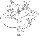
- FIG. 1 depicts a welding system 10.
- the welding system 10 comprises a first manipulator 12 and a second manipulator 14.
- Each one of the first and the second manipulators 12, 14 are respectively equipped with a first welding head 16 and a second welding head 18.
- a controller 20 is in communication with both the first manipulator 12 and the second manipulator 14.
- the first and second manipulators 12, 14 are typically industrial robots such as the ones manufactured by companies like Kuka or Fanuc and are well known in the art.
- the first welding head 16, which is mounted to the first manipulator 12, is, according to the present invention, equipped with a first welding device 22 of the high energy welding type, such as laser, plasma or electron beam types.
- the role of the first welding device 22 is, according to the present invention, to melt a material of components to be welded 30 along a welding joint 26.
- the first welding head 16 also comprises a joint detection device 24.
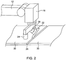
- the first welding head 16 may also comprise a pivot 28 to which is mounted the first welding device 22 so that it may be independently pivoted with respect to the joint detection device 24. This allows to better reach a material of the components to be welded 30 along the welding joint 26. A detail of this arrangement is also shown in Figure 2 .
- the second welding head 18, connected to the second manipulator 14, is, according to the present invention, equipped with a second welding device 32.
- the second welding device 32 is typically of an electrode type such as GMAW, GTAW, PAW, SMAW or any other electrode type well known in the art.
- the role of the second welding device 32 is, according to the present invention, to add filler material 33 to a weld pool created between the components to be welded 30.
- the controller 20 is connected to the first manipulator 12 to control its movements, and thereby the movements of the first welding head 16, the first welding device 22 and the joint detection device 24.
- the controller 20 is also connected to the joint detection device 24 and to the first welding device 22 so as to control and obtain feedback and information from them such as welding joint characteristics.
- the controller 20 has a predetermined representation of the welding joint trajectory that is electronically stored in its memory.
- this predetermined welding trajectory 34 may be remotely stored and be accessible by the controller 20 through any other access such as USB, remote, Wi-Fi or cloud access.
- the controller 20 is operative to determine a first corrected trajectory.
- the controller 20 is connected to the second manipulator 14 and controls its movement, and thereby the movements of the second welding head 18 and that of the second welding device 32.
- the controller 20 may also be connected to the second welding device 32 so as to adjust its parameters.
- the controller 20 is operative to determine a second corrected trajectory based on the predetermined welding trajectory 34, on the welding joint characteristics and on a distance between the first welding device 22 and the second welding device 32. This distance may be predetermined or continuously adapted during the welding process.
- the controller 20 also requires access to the predetermined welding trajectory. Similarly to the controller 20, the controller 20 may access the predetermined welding trajectory by either having it electronically stored in its memory, or by remotely accessing it through USB, remote, Wi-Fi or cloud access or even by being in communication with the controller 20 and receiving it from it.
- the joint detection device 24 is according to the present invention a camera combined with recognition software.
- the joint detection device 24 is used to detect welding joint characteristics and feed this information back to the controller 20.
- the joint detection device 24 may also be connected to the controller 20 to feed the same information.
- the components to be welded 30 are first positioned on a welding fixture 36 so that the welding joint 26 is always located in a repeatable location with respect to the first and second manipulators 12, 14.
- the controller 20 directs the first manipulator 12 so that the joint detection device 24 is directed to a welding joint start 38 according to the predetermined welding trajectory 34 and may read the real position of the start of the welding joint 26 at 102.
- the joint detection device 24 keeps on reading the real position of the weld joint 26.
- the controller 20 starts calculating a corrected welding trajectory 44 at 104, as will be described in more details below.
- the controller 20 then directs the second manipulator 14 to place the second welding device 32 behind the first welding device 22 at a first distance 40 at 108.
- This first distance 40 is initially set at a predetermined value. Typically, the first distance 40 is initially set at a value in the order of 5 to 50 mm.
- Figure 5 now concurrently referred to, represents the first and the second welding devices 22, 32 as they are in the process of welding the components to be welded 30 along the welding joint 26.
- the first welding device 22 and the second welding device 32 are separated by the first distance 40.
- This distance is dependent on the physical space available between the first and the second welding devices 22, 32, of the desired welding speed and on the desired characteristics of the weld to be performed between the components to be welded 30.
- the first distance 40 may be calculated so that the point of actions of both the first and the second welding devices 22, 32 are within a common welding pool.
- the first distance 40 may vary as a function of many parameters, such as welding speed, weld joint characteristics, welding joint topology, welding parameters, etc.
- the controller 20 sends to the first welding device 22 and to the first manipulator 12 the command to weld along the first corrected trajectory 46.
- the joint detection device 24 keeps on reading the real position of the welding joint 26 as well as its characteristics. These readings are taken at constant time intervals (for example, every 0.075 sec) and continuously sent to the controller 20 and stored in its memory at 114. This information is communicated to the controller 20 as joint readings 42.
- the joint readings 42 comprise information about the real position of the welding joint 26, information about a gap or a mismatch between the components to be welded 30, as well as information about characteristics of the weld joint 26.
- These characteristics may include information such as the type of welding joint (filet, end-to-end, corner, overlap, butt, bevel, J, etc).
- the controller 20 Based on predetermined information stored in the controller 20, such as the predetermined welding trajectory, and on the joint readings 42, the controller 20 calculates a series of corresponding corrected points used to determine the corrected welding trajectory 44 at 104. These corrected points are also stored in the controller's 20 memory at 105 as the corrected welding trajectory 44.
- the corrected welding trajectory 44 has a profile which is followed by the first and the second welding devices 22, 32, albeit determined differently for both welding devices as is detailed below.
- the predetermined welding trajectory 34 and the corrected welding trajectory 44 are depicted in Figure 6 , now concurrently referred to.
- the first welding head 16 Since the first welding head 16 carries both the joint detection device 24 and the first welding device 22 which are located at a second distance 45 from each other, the first welding head 16 must be controlled in such a way that the joint detecting device 24 keeps on following the predetermined welding trajectory 34 while the first welding device 22 follows a first corrected trajectory 46. This is usually performed with native softwares from manipulators manufacturers. As shown in Figure 6 , the first corrected trajectory 46 is in fact the corrected welding trajectory 44 which is transmitted to the first manipulator 12 with a first time delay 48. Determination of the first corrected trajectory 46 is done at 109 and continues as long as the joint detection device 24 detects the welding joint 26.
- This first time delay 48 compensates for the fact that the joint detection device 24 and the first welding device 22 are not located at the same place in time due to the second distance 45 between them.
- the first corrected trajectory 46 is sent by the controller 20 to the first manipulator 12 in the form of a first corrected trajectory signal 50 so that the first manipulator 12 may correctly position the first welding device 22 over the welding joint 26.
- the controller 20 may also send a first welding parameters signal 52 to adjust the welding parameters of the first welding device 22.
- the welding parameters of the first welding device 22 may include information such as power, position, angle, etc.
- a second time delay 54 must be added to the corrected trajectory 34 when a second corrected trajectory 56 is communicated by the controller 20 to the second manipulator 14 at 114.
- This second time delay 54 is determined using the speed of the first and second welding devices 22, 32 and the total distance 57 between the joint detection device 24 and the second welding device 32, where this total distance 57 is the sum of the second distance 45 and the first distance 40.
- the second corrected trajectory 56 is sent in the form of a second corrected trajectory signal 58 to the second manipulator 14.
- the controller 20 sends to the second welding device 32 and to the second manipulator 14 the command to weld along the second corrected trajectory 56.
- the controller 20 may also send a second welding parameters signal 60 to adjust the welding parameters of the second welding device 32.
- the welding parameters of the second welding device 32 may include information such as welding current, welding voltage, material feeding rate, etc.
- the second corrected trajectory 56 could be determined using the first corrected trajectory 46 and adding to it a delay corresponding to the first distance 40.
- first distance 40 may be affected by the precision in speed and trajectory of the first and the second manipulators 12 and 14, it may be preferable to continuously assess the first distance 40, for example at regular time intervals, and adjust it depending on welding conditions (for example welding joint type or gap size between the components to be welded 30), characteristics of the first and second welding devices 22, 32, or characteristics of the welding joint 26, etc. Consequently, the second time delay 54 may be continuously adjusted and varied so as to ensure that the point of action of both the first and the second welding devices 22, 32 is within the same fusion bath.
- the controller 12 adds a flag to the corrected welding trajectory 44 at 116.
- this flag is either added to the first welding joint 26 detected by the controller 12, either in the first corrected trajectory 46 or in the second corrected trajectory 56 at 117, it respectively stops the welding operation of the first welding device 22 at 118 or of the second welding device at 120.
Landscapes
- Engineering & Computer Science (AREA)
- Physics & Mathematics (AREA)
- Mechanical Engineering (AREA)
- Optics & Photonics (AREA)
- Plasma & Fusion (AREA)
- Robotics (AREA)
- Multimedia (AREA)
- Manipulator (AREA)
- Laser Beam Processing (AREA)
- Numerical Control (AREA)
Description
- The present invention generally relates to a method of welding components along a welding joint according to the preamble of claim 1 (see for example
EP2 314 406 ). More specifically, the invention relates to a hybrid laser welding method that uses two robots. - Automated hybrid laser/arc welding typically uses a laser welding device in combination with a conventional arc welding device. Both the laser welding device and the arc welding device are mounted together on a robot. The laser is aimed at the components to be welded and the laser basically melts surrounding a welding joint while the arc follows, filling the gap with new material.
- There are certain drawbacks to this arrangement. Indeed, because of the size of the assembly of both the laser welding device and the arc welding device, it is difficult to reach internal corners of welded assemblies. Moreover, when a joint detection device is further added to the welding heads, the fixed installation of the joint detection device, laser welding device and arc welding device makes it impossible to precisely follow a curve, whether internal or external, since the three devices are fixedly aligned.
- There is therefore a need for an improved hybrid laser welding system providing an improved reachability.
- Document
EP2 314 406 discloses a welding method using two welding robot system, each provided with a single electrode. Each welding electrode is provided with an arc sensor, which is used to determine a deviation from a welding line. According to one embodiment, one of the welding robots is a master and the other a slave. The operation of a master manipulator carrying the master electrode is controlled based on the signal from the master arc sensor so as to correct the deviation of the master electrode from the welding line. If the validity of the arc sensor of the master is confirmed, the master locus correction by the arc sensor of the master is also reflected in the slave, i.e. the arc sensor correction of the master is also used in the slave. If the arc sensor of the master is invalid, the arc sensor of the slave is used to operate the slave. - To reduce waiting time of welding robots in a welding system including a plurality of welding robots, a welding system including a first welding robot and a second welding robot is described in
JP2010149148 - A real-time seam tracking for robotic laser welding using a single laser head and a visual seam-tracking sensor is disclosed in the article "real-time seam tracking for robotic laser welding using trajectory-based control" by M. de Graaf et al. in Control Engineering Practice 18(2010) 944-953.
- It is an object of the present invention to provide a hybrid laser welding method that overcome or mitigate one or more disadvantages of known laser welding systems and methods, or at least provide useful alternatives.
- Accordingly, there is provided a method as defined in claim 1.
- The method may be implemented with a welding system comprising a first and a second manipulator, respectively having a first and a second welding head, and a controller. The first welding head, which is connected to the first manipulator, has a joint detection device and a first welding device. The joint detection device is operative to read welding joint characteristics, such as a joint type or a gap between components to be welded, along a welding joint. The second welding head, which is connected to the second manipulator, is equipped with a second welding device. The controller is in communication with both the first and the second manipulators as well as with the joint detection device. The controller determines a corrected trajectory based on a predetermined welding trajectory and on the welding joint characteristics read by the joint detection device. The controller communicates the corrected trajectory with a first time delay to the first manipulator and communicates the corrected trajectory with a second time delay to the second manipulator. The second time delay is a function of a distance between the joint detection device and the second welding device. In operation, the controller is operative to make the joint detection device follow the predetermined trajectory and to make the first and the second welding devices follow the corrected trajectory. Typically, the second time delay is longer that the first time delay.
- The controller is adapted to electronically store the predetermined welding trajectory. Moreover, the controller determines the second time delay so that in operation the first welding device and the second welding device each have a point of action located at a predetermined distance from each other.
- The first corrected trajectory may further be based on characteristics of the first welding device. Similarly, the second corrected trajectory may further be based on characteristics of the second welding device. As the first welding device is typically of a laser type while the second welding device is typically of an electrode type, the characteristics of the first welding device are different from the characteristics of the second welding device.
- Optionally, the first welding head may comprise a pivot, the first welding device being mounted to the pivot so that the first welding device may be pivoted with respect to the joint detection device.
- In the method, the second time delay is longer than the first time delay so that the second welding device is made to follow the first welding device.
- The method may further comprise assessing the distance between the first welding device and the second welding device. This assessing may be done at either regular time intervals or regular distance intervals travelled by the first welding device.
- The manipulating of the first welding device may be based on characteristics of the first welding device whereas the manipulating of the second welding device is based on characteristics of the second welding device. The characteristics of the first welding device may be different from those of the second welding device since typically, the first welding device is a laser and the second welding device is an arc welding device.
- Optionally, the method may further comprise pivoting the first welding device with respect to the joint detection device.
- These and other features of the present invention will become more apparent from the following description in which reference is made to the appended drawings wherein:
-
Figure 1 is an isometric view of a welding system for carrying out the method of the invention; -
Figure 2 is an isometric view of a detail of a first welding head of the welding system ofFigure 1 ; -
Figure 3 is a schematic view of a communication system between different elements of the welding system ofFigure 1 ; -
Figure 4 is a schematic view of the first and second welding heads as they are positioned at a start of a welding joint in accordance with an embodiment; -
Figure 5 is a schematic view of the first and second welding heads as they are positioned along the welding joint ofFigure 4 ; -
Figure 6 is a schematic view of trajectories sent to manipulators of the welding system ofFigure 1 . -
Figure 7 is a flowchart of the process followed by a controller to control the manipulators of the welding system ofFigure 1 . - The present invention relates to an adaptive hybrid laser/arc welding method that uses two robots to which are mounted two separate welding heads. A joint detection device is mounted to one of the welding head so as to read characteristics of a welding joint. A controller uses the readings of the welding joint characteristics to correct a predetermined welding trajectory and sends the information to at least one of the two robots. This hybrid laser/arc welding system allows reaching welding areas which are usually difficult to reach and following welding paths that are usually impossible to follow with a system where both welding heads are mounted on a single robot while maintaining the real-time adaptability of the welding system.
-
Figure 1 depicts awelding system 10. Thewelding system 10 comprises afirst manipulator 12 and asecond manipulator 14. Each one of the first and thesecond manipulators first welding head 16 and asecond welding head 18. Acontroller 20 is in communication with both thefirst manipulator 12 and thesecond manipulator 14. - The first and
second manipulators - The
first welding head 16, which is mounted to thefirst manipulator 12, is, according to the present invention, equipped with afirst welding device 22 of the high energy welding type, such as laser, plasma or electron beam types. The role of thefirst welding device 22 is, according to the present invention, to melt a material of components to be welded 30 along awelding joint 26. - The
first welding head 16 also comprises ajoint detection device 24. Optionally, thefirst welding head 16 may also comprise apivot 28 to which is mounted thefirst welding device 22 so that it may be independently pivoted with respect to thejoint detection device 24. This allows to better reach a material of the components to be welded 30 along the welding joint 26. A detail of this arrangement is also shown inFigure 2 . - The
second welding head 18, connected to thesecond manipulator 14, is, according to the present invention, equipped with asecond welding device 32. Thesecond welding device 32 is typically of an electrode type such as GMAW, GTAW, PAW, SMAW or any other electrode type well known in the art. The role of thesecond welding device 32 is, according to the present invention, to addfiller material 33 to a weld pool created between the components to be welded 30. -
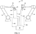
Figure 3 is now concurrently referred to. Different communication connections between elements will now be described. It is envisioned that these connections may be wired or wireless, but are nevertheless schematically represented in the attached figures by lines between elements. - The
controller 20 is connected to thefirst manipulator 12 to control its movements, and thereby the movements of thefirst welding head 16, thefirst welding device 22 and thejoint detection device 24. Thecontroller 20 is also connected to thejoint detection device 24 and to thefirst welding device 22 so as to control and obtain feedback and information from them such as welding joint characteristics. - The
controller 20 has a predetermined representation of the welding joint trajectory that is electronically stored in its memory. Optionally, thispredetermined welding trajectory 34 may be remotely stored and be accessible by thecontroller 20 through any other access such as USB, remote, Wi-Fi or cloud access. - Based on the
predetermined welding trajectory 34, on welding joint characteristics and on a distance between thejoint detection device 24 and thefirst welding device 22, thecontroller 20 is operative to determine a first corrected trajectory. - Similarly, the
controller 20 is connected to thesecond manipulator 14 and controls its movement, and thereby the movements of thesecond welding head 18 and that of thesecond welding device 32. Thecontroller 20 may also be connected to thesecond welding device 32 so as to adjust its parameters. Thecontroller 20 is operative to determine a second corrected trajectory based on thepredetermined welding trajectory 34, on the welding joint characteristics and on a distance between thefirst welding device 22 and thesecond welding device 32. This distance may be predetermined or continuously adapted during the welding process. - The
controller 20 also requires access to the predetermined welding trajectory. Similarly to thecontroller 20, thecontroller 20 may access the predetermined welding trajectory by either having it electronically stored in its memory, or by remotely accessing it through USB, remote, Wi-Fi or cloud access or even by being in communication with thecontroller 20 and receiving it from it. - The
joint detection device 24 is according to the present invention a camera combined with recognition software. Thejoint detection device 24 is used to detect welding joint characteristics and feed this information back to thecontroller 20. Optionally, thejoint detection device 24 may also be connected to thecontroller 20 to feed the same information. -
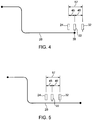
Figure 4 andFigure 7 are now concurrently referred to. In preparation for a welding operation, the components to be welded 30 are first positioned on a welding fixture 36 so that the welding joint 26 is always located in a repeatable location with respect to the first andsecond manipulators seam approach phase 100, thecontroller 20 directs thefirst manipulator 12 so that thejoint detection device 24 is directed to a weldingjoint start 38 according to thepredetermined welding trajectory 34 and may read the real position of the start of the welding joint 26 at 102. As thecontroller 20 then directs thefirst manipulator 12 so that thefirst welding device 22 is placed at the weldingjoint start 38 at 106, thejoint detection device 24 keeps on reading the real position of the weld joint 26. Thecontroller 20 starts calculating a correctedwelding trajectory 44 at 104, as will be described in more details below. Thecontroller 20 then directs thesecond manipulator 14 to place thesecond welding device 32 behind thefirst welding device 22 at afirst distance 40 at 108. Thisfirst distance 40 is initially set at a predetermined value. Typically, thefirst distance 40 is initially set at a value in the order of 5 to 50 mm. -
Figure 5 , now concurrently referred to, represents the first and thesecond welding devices first welding device 22 and thesecond welding device 32 are separated by thefirst distance 40. This distance is dependent on the physical space available between the first and thesecond welding devices first distance 40 may be calculated so that the point of actions of both the first and thesecond welding devices first distance 40 may vary as a function of many parameters, such as welding speed, weld joint characteristics, welding joint topology, welding parameters, etc. - At 110, the
controller 20 sends to thefirst welding device 22 and to thefirst manipulator 12 the command to weld along the first correctedtrajectory 46. As the welding operation takes place and thejoint detection device 24 is guided along thepredetermined welding trajectory 34, thejoint detection device 24 keeps on reading the real position of the welding joint 26 as well as its characteristics. These readings are taken at constant time intervals (for example, every 0.075 sec) and continuously sent to thecontroller 20 and stored in its memory at 114. This information is communicated to thecontroller 20 asjoint readings 42. Thejoint readings 42 comprise information about the real position of the welding joint 26, information about a gap or a mismatch between the components to be welded 30, as well as information about characteristics of the weld joint 26. These characteristics may include information such as the type of welding joint (filet, end-to-end, corner, overlap, butt, bevel, J, etc). Based on predetermined information stored in thecontroller 20, such as the predetermined welding trajectory, and on thejoint readings 42, thecontroller 20 calculates a series of corresponding corrected points used to determine the correctedwelding trajectory 44 at 104. These corrected points are also stored in the controller's 20 memory at 105 as the correctedwelding trajectory 44. The correctedwelding trajectory 44 has a profile which is followed by the first and thesecond welding devices predetermined welding trajectory 34 and the correctedwelding trajectory 44 are depicted inFigure 6 , now concurrently referred to. - Since the
first welding head 16 carries both thejoint detection device 24 and thefirst welding device 22 which are located at asecond distance 45 from each other, thefirst welding head 16 must be controlled in such a way that the joint detectingdevice 24 keeps on following thepredetermined welding trajectory 34 while thefirst welding device 22 follows a first correctedtrajectory 46. This is usually performed with native softwares from manipulators manufacturers. As shown inFigure 6 , the first correctedtrajectory 46 is in fact the correctedwelding trajectory 44 which is transmitted to thefirst manipulator 12 with afirst time delay 48. Determination of the first correctedtrajectory 46 is done at 109 and continues as long as thejoint detection device 24 detects thewelding joint 26. Thisfirst time delay 48 compensates for the fact that thejoint detection device 24 and thefirst welding device 22 are not located at the same place in time due to thesecond distance 45 between them. The first correctedtrajectory 46 is sent by thecontroller 20 to thefirst manipulator 12 in the form of a first correctedtrajectory signal 50 so that thefirst manipulator 12 may correctly position thefirst welding device 22 over the welding joint 26. Optionally, thecontroller 20 may also send a first welding parameters signal 52 to adjust the welding parameters of thefirst welding device 22. The welding parameters of thefirst welding device 22 may include information such as power, position, angle, etc. - Similarly, because of the
first distance 40 between thefirst welding device 22 and thesecond welding device 32, asecond time delay 54 must be added to the correctedtrajectory 34 when a second correctedtrajectory 56 is communicated by thecontroller 20 to thesecond manipulator 14 at 114. Thissecond time delay 54 is determined using the speed of the first andsecond welding devices total distance 57 between thejoint detection device 24 and thesecond welding device 32, where thistotal distance 57 is the sum of thesecond distance 45 and thefirst distance 40. The second correctedtrajectory 56 is sent in the form of a second correctedtrajectory signal 58 to thesecond manipulator 14. At 115, thecontroller 20 sends to thesecond welding device 32 and to thesecond manipulator 14 the command to weld along the second correctedtrajectory 56. Optionally, thecontroller 20 may also send a second welding parameters signal 60 to adjust the welding parameters of thesecond welding device 32. The welding parameters of thesecond welding device 32 may include information such as welding current, welding voltage, material feeding rate, etc. - Alternatively and according also to the present invention, the second corrected
trajectory 56 could be determined using the first correctedtrajectory 46 and adding to it a delay corresponding to thefirst distance 40. - It is preferable that a point of action of each of the
first welding device 22 and thesecond welding device 32 be kept at a predetermined distance from each other. Hence, since thefirst distance 40 may be affected by the precision in speed and trajectory of the first and thesecond manipulators first distance 40, for example at regular time intervals, and adjust it depending on welding conditions (for example welding joint type or gap size between the components to be welded 30), characteristics of the first andsecond welding devices second time delay 54 may be continuously adjusted and varied so as to ensure that the point of action of both the first and thesecond welding devices - When the
joint detection device 24 detects the end of the welding joint 26, thecontroller 12 adds a flag to the correctedwelding trajectory 44 at 116. When this flag is either added to the first welding joint 26 detected by thecontroller 12, either in the first correctedtrajectory 46 or in the second correctedtrajectory 56 at 117, it respectively stops the welding operation of thefirst welding device 22 at 118 or of the second welding device at 120. - The present invention has been described with regard to preferred embodiments. The description as much as the drawings were intended to help the understanding of the invention, rather than to limit its scope. It will be apparent to one skilled in the art that various modifications may be made to the invention without departing from the scope of the invention as defined in the appended claims.
Claims (12)
- A method of welding components (30) along a welding joint (26), the method comprising:(a) causing by a controller (20) a first manipulator (12) to manipulate a joint detection device (24) along a predetermined welding trajectory (34);(b) detecting by the joint detection device (24) welding joint characteristics;(c) determining by the controller (20) a corrected trajectory (44) based on the predetermined trajectory (34) and on the detected welding joint characteristics;characterized in that in step (b) the joint detection device (24) detects said welding joint characteristics by means of a camera combined with a recognition software, and the method further comprises:(d) causing by the controller (20) the first manipulator (12) to manipulate a first welding device (22) of the high energy welding type, such as laser, plasma or electron beam types along a first corrected trajectory (46) after a first time delay (48) determined by the controller (20) as a function of the corrected trajectory (44) and a distance (45) between the joint detection device (24) and the first welding device (22); and(e) causing by the controller (20) a second manipulator (14) to manipulate a second welding device (32) of an electrode type along a second corrected trajectory (56) after a second time delay (54) determined by the controller (20) as a function of the corrected trajectory (44) and a distance (57) between the joint detection device (24) and the second welding device (32) or as a function of the corrected trajectory (44) and a distance (40) between the first welding device (22) and the second welding device (32);wherein the first welding device melts a material of the components to be welded (30) along the welding joint (26), and the second welding device (32) adds filler material (33) to the weld pool created between the components to be welded (30).
- The method of claim 1 further comprising assessing the distance (40) between the first welding device (22) and the second welding device (32).
- The method of claim 2 wherein the step of assessing is done at one of regular time intervals and regular distance intervals travelled by the first welding device (22).
- The method of claim 3 wherein the manipulating of the first welding device (22) is based on characteristics of the first welding device (22) and wherein the manipulating of the second welding device (32) is based on characteristics of the second welding device (32), the characteristics of the first welding device (22) being different from the characteristics of the second welding device (32).
- The method of any one of the preceding claims, wherein the second time delay is longer than the first time delay so that the second welding device (32) follows the first welding device (22).
- The method of any one of the preceding claims, further comprising providing a laser as the first welding device (22) and a welding electrode as the second welding device (32).
- The method of any one of the preceding claims, further comprising pivoting the first welding device (32) with respect to the joint detection device (24).
- The method of any one of the preceding claims, wherein a first welding head (16) is mounted to the first manipulator (12) and carries the first welding device (22) and the joint detection device (24) which are located at a distance (45) from each other, and wherein a second welding head (18), connected to the second manipulator (14), is equipped with the second welding device (32).
- The method of any one of the preceding claims, further comprising varying the distance (40) between the first welding device (22) and the second welding device (32) as a function of parameters, such as welding speed, weld joint characteristics, welding joint topology, welding parameters.
- The method of any one of the preceding claims, further comprising continuously assessing the distance (40) between the first welding device (22) and the second welding device (32), for example at regular time intervals, and adjusting it depending on welding conditions, wherein the second time delay (54) is continuously adjusted and varied so as to ensure that the point of action of both the first and the second welding devices (22, 32) is within the same fusion bath.
- The method of any one of the preceding claims, wherein the detected joint characteristics comprise information about a real position of the welding joint (26), information about a gap or a mismatch between the components to be welded (30), as well as information about characteristics of the welding joint (26).
- The method of any one of the preceding claims, wherein the second time delay (54) is determined using the speed of the first and second welding devices (22, 32) and the distance (57) between the joint detection device (24) and the second welding device (32), where the distance (57)) between the joint detection device (24) and the second welding device (32) is the sum of the distance (45) between the joint detection device (24) and the first welding device (22) and the distance (40) between the first welding device (22) and the second welding device (32).
Priority Applications (1)
| Application Number | Priority Date | Filing Date | Title |
|---|---|---|---|
| PL15764457T PL3119552T3 (en) | 2014-03-17 | 2015-03-16 | Method of welding components along a welding joint using two robots |
Applications Claiming Priority (2)
| Application Number | Priority Date | Filing Date | Title |
|---|---|---|---|
| US201461953996P | 2014-03-17 | 2014-03-17 | |
| PCT/CA2015/000165 WO2015139116A1 (en) | 2014-03-17 | 2015-03-16 | Hybrid laser welding system and method using two robots |
Publications (3)
| Publication Number | Publication Date |
|---|---|
| EP3119552A1 EP3119552A1 (en) | 2017-01-25 |
| EP3119552A4 EP3119552A4 (en) | 2017-04-19 |
| EP3119552B1 true EP3119552B1 (en) | 2021-01-27 |
Family
ID=54143574
Family Applications (1)
| Application Number | Title | Priority Date | Filing Date |
|---|---|---|---|
| EP15764457.6A Active EP3119552B1 (en) | 2014-03-17 | 2015-03-16 | Method of welding components along a welding joint using two robots |
Country Status (6)
| Country | Link |
|---|---|
| US (1) | US10478917B2 (en) |
| EP (1) | EP3119552B1 (en) |
| CN (1) | CN106457468B (en) |
| CA (1) | CA2941153C (en) |
| PL (1) | PL3119552T3 (en) |
| WO (1) | WO2015139116A1 (en) |
Families Citing this family (21)
| Publication number | Priority date | Publication date | Assignee | Title |
|---|---|---|---|---|
| US9789603B2 (en) | 2011-04-29 | 2017-10-17 | Sarcos Lc | Teleoperated robotic system |
| CN107283060A (en) * | 2017-06-07 | 2017-10-24 | 广东省焊接技术研究所(广东省中乌研究院) | A kind of laser-arc is combined multi-pass welding method |
| CN109975302B (en) * | 2017-12-28 | 2021-06-18 | 中核建中核燃料元件有限公司 | Automatic detection device of grillwork outward appearance of brazing |
| CN108672930A (en) * | 2018-07-18 | 2018-10-19 | 武汉锐科光纤激光技术股份有限公司 | A kind of ear nail robot welding system and method |
| US11251355B2 (en) | 2019-03-05 | 2022-02-15 | International Business Machines Corporation | Resonance frequency adjustment for fixed-frequency qubits |
| CN109877459B (en) * | 2019-03-14 | 2024-06-11 | 华工法利莱切焊系统工程有限公司 | Angle adjuster assembly welding process and angle adjuster assembly welding system |
| CN109848562A (en) * | 2019-04-15 | 2019-06-07 | 湖北航嘉麦格纳座椅系统有限公司 | The welding system and method for angle adjustor |
| CN110977260B (en) * | 2019-12-17 | 2021-08-17 | 易思维(杭州)科技有限公司 | Intelligent repair welding system and follow-up repair welding method for body-in-white |
| WO2022016152A1 (en) | 2020-07-17 | 2022-01-20 | Path Robotics, Inc. | Real time feedback and dynamic adjustment for welding robots |
| CN112705851A (en) * | 2020-12-22 | 2021-04-27 | 江苏华宸激光智能装备有限公司 | Large-scale plate welding equipment based on laser-electric arc hybrid welding |
| US11794345B2 (en) * | 2020-12-31 | 2023-10-24 | Sarcos Corp. | Unified robotic vehicle systems and methods of control |
| MX2023009878A (en) | 2021-02-24 | 2024-01-08 | Path Robotics Inc | AUTONOMOUS WELDING ROBOTS. |
| CN112935551A (en) * | 2021-04-15 | 2021-06-11 | 昆山市华昌散热器有限公司 | Novel efficient welding equipment for radiator |
| US12277369B2 (en) | 2021-10-18 | 2025-04-15 | Path Robotics, Inc. | Generating simulated weld paths for a welding robot |
| CA3239078A1 (en) | 2021-11-19 | 2023-05-25 | Path Robotics, Inc. | Machine learning logic-based adjustment techniques for robots |
| US12508665B2 (en) * | 2022-04-19 | 2025-12-30 | Path Robotics, Inc. | Autonomous assembly robots |
| CN115008093B (en) * | 2022-06-14 | 2023-03-14 | 广东天太机器人有限公司 | Multi-welding-point welding robot control system and method based on template identification |
| US12521884B2 (en) | 2022-07-26 | 2026-01-13 | Path Robotics, Inc. | Techniques for multipass welding |
| EP4403316A1 (en) * | 2023-01-19 | 2024-07-24 | Siemens Aktiengesellschaft | Synchronization method for coordinated execution of work steps for machining a workpiece |
| CN117733305B (en) * | 2024-02-20 | 2024-04-26 | 四川华束科技有限公司 | Sealed-off type electron gun and non-vacuum electron beam welding robot |
| CN119387941B (en) * | 2024-12-31 | 2025-03-14 | 杭州联核科技有限公司 | Automatic butt welding device of forklift drive axle |
Family Cites Families (9)
| Publication number | Priority date | Publication date | Assignee | Title |
|---|---|---|---|---|
| US4531192A (en) * | 1982-09-23 | 1985-07-23 | Crc Welding Systems, Inc. | Apparatus and method for sensing a workpiece with an electrical arc |
| FI117426B (en) | 2003-06-12 | 2006-10-13 | Aker Yards Oy | Method for controlling welding of a three-dimensional structure |
| JP5428136B2 (en) * | 2007-04-23 | 2014-02-26 | 株式会社安川電機 | Robot system |
| WO2010021094A1 (en) * | 2008-08-19 | 2010-02-25 | パナソニック株式会社 | Composite welding method and composite welding device |
| US20100078412A1 (en) * | 2008-09-30 | 2010-04-01 | Caterpillar Inc. | Hybrid welding method |
| JP5495546B2 (en) | 2008-12-25 | 2014-05-21 | 株式会社小松製作所 | Welding system and method for controlling welding system |
| WO2010098030A1 (en) | 2009-02-25 | 2010-09-02 | パナソニック株式会社 | Welding method and welding system |
| US10384293B2 (en) * | 2011-04-29 | 2019-08-20 | Lincoln Global, Inc. | Method and apparatus for heavy plate joining with hybrid laser and submerged-arc welding process |
| CN202438792U (en) * | 2011-12-20 | 2012-09-19 | 徐州工程学院 | Control system for welding robot |
-
2015
- 2015-03-16 EP EP15764457.6A patent/EP3119552B1/en active Active
- 2015-03-16 CN CN201580025064.XA patent/CN106457468B/en active Active
- 2015-03-16 US US15/124,770 patent/US10478917B2/en active Active
- 2015-03-16 WO PCT/CA2015/000165 patent/WO2015139116A1/en not_active Ceased
- 2015-03-16 CA CA2941153A patent/CA2941153C/en active Active
- 2015-03-16 PL PL15764457T patent/PL3119552T3/en unknown
Non-Patent Citations (1)
| Title |
|---|
| None * |
Also Published As
| Publication number | Publication date |
|---|---|
| CA2941153A1 (en) | 2015-09-24 |
| WO2015139116A1 (en) | 2015-09-24 |
| PL3119552T3 (en) | 2021-05-31 |
| US10478917B2 (en) | 2019-11-19 |
| CA2941153C (en) | 2018-06-05 |
| EP3119552A4 (en) | 2017-04-19 |
| US20170072507A1 (en) | 2017-03-16 |
| EP3119552A1 (en) | 2017-01-25 |
| CN106457468A (en) | 2017-02-22 |
| CN106457468B (en) | 2019-06-28 |
Similar Documents
| Publication | Publication Date | Title |
|---|---|---|
| EP3119552B1 (en) | Method of welding components along a welding joint using two robots | |
| CN111390915B (en) | An AI-based automatic weld path recognition method | |
| JP6467646B2 (en) | Robot control method | |
| JP5715809B2 (en) | Robot work program creation method, robot work program creation device, and robot control system | |
| KR102584173B1 (en) | Welding control method of portable welding robot, welding control device, portable welding robot and welding system | |
| JP6359847B2 (en) | Interference avoidance device | |
| JP2021504140A (en) | Methods and systems using smart torches with position tracking in robot welding | |
| US10394216B2 (en) | Method and system for correcting a processing path of a robot-guided tool | |
| EP3630404A1 (en) | An apparatus and a method for automated seam welding of a work piece comprising a base plate with a pattern of upstanding profiles | |
| JP2011138275A (en) | Control device of arc welding robot, and program | |
| EP2974819B1 (en) | Arc welding system, method for performing arc welding | |
| CN109926703B (en) | Welding position detection device, welding position detection method, and welding robot system | |
| CN105312731A (en) | Delivery side displacement sensing based automatic tracking method for inner weld seam of spiral steel pipe | |
| US20150076128A1 (en) | Weld monitoring apparatus | |
| JP5513206B2 (en) | Method and apparatus for adjusting wire protrusion length of welding robot | |
| JP6405168B2 (en) | Scanning control device, welding robot system, and scanning control method | |
| KR102399985B1 (en) | Welding carriage apparatus corresponding to arbitrary fillet angle and method for driving the same | |
| KR101615903B1 (en) | Automatic welding control device | |
| KR101412336B1 (en) | Arc welding apparatus | |
| US20220111460A1 (en) | A method for automatic welding of a structural steel assembly and an automatic welding system for welding of a structural steel assembly | |
| US20040256437A1 (en) | Weld guidance system and method | |
| JP6955414B2 (en) | Welding robot system and welding method using welding robot system | |
| US20250046216A1 (en) | Method for generating teaching program and apparatus for generating teaching program | |
| RU121765U1 (en) | MICROPROCESSOR COMPLEX OF MONITORING AND CONTROL OF THE PROCESS OF WELDING RING PIP JOINS | |
| Harwig et al. | Semiadaptive synergic-fill welding tractor for ship unit erection |
Legal Events
| Date | Code | Title | Description |
|---|---|---|---|
| STAA | Information on the status of an ep patent application or granted ep patent |
Free format text: STATUS: THE INTERNATIONAL PUBLICATION HAS BEEN MADE |
|
| PUAI | Public reference made under article 153(3) epc to a published international application that has entered the european phase |
Free format text: ORIGINAL CODE: 0009012 |
|
| STAA | Information on the status of an ep patent application or granted ep patent |
Free format text: STATUS: REQUEST FOR EXAMINATION WAS MADE |
|
| 17P | Request for examination filed |
Effective date: 20161014 |
|
| AK | Designated contracting states |
Kind code of ref document: A1 Designated state(s): AL AT BE BG CH CY CZ DE DK EE ES FI FR GB GR HR HU IE IS IT LI LT LU LV MC MK MT NL NO PL PT RO RS SE SI SK SM TR |
|
| AX | Request for extension of the european patent |
Extension state: BA ME |
|
| A4 | Supplementary search report drawn up and despatched |
Effective date: 20170321 |
|
| RIC1 | Information provided on ipc code assigned before grant |
Ipc: B25J 9/18 20060101ALI20170315BHEP Ipc: B23K 26/348 20140101ALI20170315BHEP Ipc: B23K 26/044 20140101AFI20170315BHEP Ipc: B23K 28/02 20140101ALI20170315BHEP Ipc: B23K 15/00 20060101ALI20170315BHEP Ipc: B25J 19/02 20060101ALI20170315BHEP Ipc: B23K 10/02 20060101ALI20170315BHEP Ipc: B25J 9/16 20060101ALI20170315BHEP Ipc: B23K 37/02 20060101ALI20170315BHEP Ipc: B23K 9/167 20060101ALI20170315BHEP Ipc: B23K 26/26 20140101ALI20170315BHEP Ipc: B23K 26/08 20140101ALI20170315BHEP Ipc: B23K 9/173 20060101ALI20170315BHEP |
|
| DAV | Request for validation of the european patent (deleted) | ||
| DAX | Request for extension of the european patent (deleted) | ||
| STAA | Information on the status of an ep patent application or granted ep patent |
Free format text: STATUS: EXAMINATION IS IN PROGRESS |
|
| 17Q | First examination report despatched |
Effective date: 20190405 |
|
| GRAP | Despatch of communication of intention to grant a patent |
Free format text: ORIGINAL CODE: EPIDOSNIGR1 |
|
| STAA | Information on the status of an ep patent application or granted ep patent |
Free format text: STATUS: GRANT OF PATENT IS INTENDED |
|
| INTG | Intention to grant announced |
Effective date: 20200810 |
|
| GRAS | Grant fee paid |
Free format text: ORIGINAL CODE: EPIDOSNIGR3 |
|
| GRAA | (expected) grant |
Free format text: ORIGINAL CODE: 0009210 |
|
| STAA | Information on the status of an ep patent application or granted ep patent |
Free format text: STATUS: THE PATENT HAS BEEN GRANTED |
|
| AK | Designated contracting states |
Kind code of ref document: B1 Designated state(s): AL AT BE BG CH CY CZ DE DK EE ES FI FR GB GR HR HU IE IS IT LI LT LU LV MC MK MT NL NO PL PT RO RS SE SI SK SM TR |
|
| REG | Reference to a national code |
Ref country code: GB Ref legal event code: FG4D |
|
| REG | Reference to a national code |
Ref country code: CH Ref legal event code: EP |
|
| REG | Reference to a national code |
Ref country code: AT Ref legal event code: REF Ref document number: 1357897 Country of ref document: AT Kind code of ref document: T Effective date: 20210215 |
|
| REG | Reference to a national code |
Ref country code: IE Ref legal event code: FG4D |
|
| REG | Reference to a national code |
Ref country code: DE Ref legal event code: R096 Ref document number: 602015065246 Country of ref document: DE |
|
| REG | Reference to a national code |
Ref country code: CH Ref legal event code: NV Representative=s name: DENNEMEYER AG, CH |
|
| REG | Reference to a national code |
Ref country code: NL Ref legal event code: MP Effective date: 20210127 |
|
| REG | Reference to a national code |
Ref country code: LT Ref legal event code: MG9D |
|
| REG | Reference to a national code |
Ref country code: AT Ref legal event code: MK05 Ref document number: 1357897 Country of ref document: AT Kind code of ref document: T Effective date: 20210127 |
|
| PG25 | Lapsed in a contracting state [announced via postgrant information from national office to epo] |
Ref country code: PT Free format text: LAPSE BECAUSE OF FAILURE TO SUBMIT A TRANSLATION OF THE DESCRIPTION OR TO PAY THE FEE WITHIN THE PRESCRIBED TIME-LIMIT Effective date: 20210527 Ref country code: LT Free format text: LAPSE BECAUSE OF FAILURE TO SUBMIT A TRANSLATION OF THE DESCRIPTION OR TO PAY THE FEE WITHIN THE PRESCRIBED TIME-LIMIT Effective date: 20210127 Ref country code: NO Free format text: LAPSE BECAUSE OF FAILURE TO SUBMIT A TRANSLATION OF THE DESCRIPTION OR TO PAY THE FEE WITHIN THE PRESCRIBED TIME-LIMIT Effective date: 20210427 Ref country code: NL Free format text: LAPSE BECAUSE OF FAILURE TO SUBMIT A TRANSLATION OF THE DESCRIPTION OR TO PAY THE FEE WITHIN THE PRESCRIBED TIME-LIMIT Effective date: 20210127 Ref country code: BG Free format text: LAPSE BECAUSE OF FAILURE TO SUBMIT A TRANSLATION OF THE DESCRIPTION OR TO PAY THE FEE WITHIN THE PRESCRIBED TIME-LIMIT Effective date: 20210427 Ref country code: HR Free format text: LAPSE BECAUSE OF FAILURE TO SUBMIT A TRANSLATION OF THE DESCRIPTION OR TO PAY THE FEE WITHIN THE PRESCRIBED TIME-LIMIT Effective date: 20210127 Ref country code: FI Free format text: LAPSE BECAUSE OF FAILURE TO SUBMIT A TRANSLATION OF THE DESCRIPTION OR TO PAY THE FEE WITHIN THE PRESCRIBED TIME-LIMIT Effective date: 20210127 Ref country code: GR Free format text: LAPSE BECAUSE OF FAILURE TO SUBMIT A TRANSLATION OF THE DESCRIPTION OR TO PAY THE FEE WITHIN THE PRESCRIBED TIME-LIMIT Effective date: 20210428 |
|
| PG25 | Lapsed in a contracting state [announced via postgrant information from national office to epo] |
Ref country code: LV Free format text: LAPSE BECAUSE OF FAILURE TO SUBMIT A TRANSLATION OF THE DESCRIPTION OR TO PAY THE FEE WITHIN THE PRESCRIBED TIME-LIMIT Effective date: 20210127 Ref country code: RS Free format text: LAPSE BECAUSE OF FAILURE TO SUBMIT A TRANSLATION OF THE DESCRIPTION OR TO PAY THE FEE WITHIN THE PRESCRIBED TIME-LIMIT Effective date: 20210127 Ref country code: AT Free format text: LAPSE BECAUSE OF FAILURE TO SUBMIT A TRANSLATION OF THE DESCRIPTION OR TO PAY THE FEE WITHIN THE PRESCRIBED TIME-LIMIT Effective date: 20210127 Ref country code: SE Free format text: LAPSE BECAUSE OF FAILURE TO SUBMIT A TRANSLATION OF THE DESCRIPTION OR TO PAY THE FEE WITHIN THE PRESCRIBED TIME-LIMIT Effective date: 20210127 |
|
| PG25 | Lapsed in a contracting state [announced via postgrant information from national office to epo] |
Ref country code: IS Free format text: LAPSE BECAUSE OF FAILURE TO SUBMIT A TRANSLATION OF THE DESCRIPTION OR TO PAY THE FEE WITHIN THE PRESCRIBED TIME-LIMIT Effective date: 20210527 |
|
| REG | Reference to a national code |
Ref country code: DE Ref legal event code: R097 Ref document number: 602015065246 Country of ref document: DE |
|
| PG25 | Lapsed in a contracting state [announced via postgrant information from national office to epo] |
Ref country code: SM Free format text: LAPSE BECAUSE OF FAILURE TO SUBMIT A TRANSLATION OF THE DESCRIPTION OR TO PAY THE FEE WITHIN THE PRESCRIBED TIME-LIMIT Effective date: 20210127 Ref country code: EE Free format text: LAPSE BECAUSE OF FAILURE TO SUBMIT A TRANSLATION OF THE DESCRIPTION OR TO PAY THE FEE WITHIN THE PRESCRIBED TIME-LIMIT Effective date: 20210127 Ref country code: MC Free format text: LAPSE BECAUSE OF FAILURE TO SUBMIT A TRANSLATION OF THE DESCRIPTION OR TO PAY THE FEE WITHIN THE PRESCRIBED TIME-LIMIT Effective date: 20210127 |
|
| PG25 | Lapsed in a contracting state [announced via postgrant information from national office to epo] |
Ref country code: SK Free format text: LAPSE BECAUSE OF FAILURE TO SUBMIT A TRANSLATION OF THE DESCRIPTION OR TO PAY THE FEE WITHIN THE PRESCRIBED TIME-LIMIT Effective date: 20210127 Ref country code: RO Free format text: LAPSE BECAUSE OF FAILURE TO SUBMIT A TRANSLATION OF THE DESCRIPTION OR TO PAY THE FEE WITHIN THE PRESCRIBED TIME-LIMIT Effective date: 20210127 Ref country code: ES Free format text: LAPSE BECAUSE OF FAILURE TO SUBMIT A TRANSLATION OF THE DESCRIPTION OR TO PAY THE FEE WITHIN THE PRESCRIBED TIME-LIMIT Effective date: 20210127 Ref country code: DK Free format text: LAPSE BECAUSE OF FAILURE TO SUBMIT A TRANSLATION OF THE DESCRIPTION OR TO PAY THE FEE WITHIN THE PRESCRIBED TIME-LIMIT Effective date: 20210127 |
|
| PLBE | No opposition filed within time limit |
Free format text: ORIGINAL CODE: 0009261 |
|
| STAA | Information on the status of an ep patent application or granted ep patent |
Free format text: STATUS: NO OPPOSITION FILED WITHIN TIME LIMIT |
|
| REG | Reference to a national code |
Ref country code: BE Ref legal event code: MM Effective date: 20210331 |
|
| 26N | No opposition filed |
Effective date: 20211028 |
|
| PG25 | Lapsed in a contracting state [announced via postgrant information from national office to epo] |
Ref country code: AL Free format text: LAPSE BECAUSE OF FAILURE TO SUBMIT A TRANSLATION OF THE DESCRIPTION OR TO PAY THE FEE WITHIN THE PRESCRIBED TIME-LIMIT Effective date: 20210127 Ref country code: LU Free format text: LAPSE BECAUSE OF NON-PAYMENT OF DUE FEES Effective date: 20210316 Ref country code: IE Free format text: LAPSE BECAUSE OF NON-PAYMENT OF DUE FEES Effective date: 20210316 |
|
| PG25 | Lapsed in a contracting state [announced via postgrant information from national office to epo] |
Ref country code: SI Free format text: LAPSE BECAUSE OF FAILURE TO SUBMIT A TRANSLATION OF THE DESCRIPTION OR TO PAY THE FEE WITHIN THE PRESCRIBED TIME-LIMIT Effective date: 20210127 |
|
| PG25 | Lapsed in a contracting state [announced via postgrant information from national office to epo] |
Ref country code: IT Free format text: LAPSE BECAUSE OF FAILURE TO SUBMIT A TRANSLATION OF THE DESCRIPTION OR TO PAY THE FEE WITHIN THE PRESCRIBED TIME-LIMIT Effective date: 20210127 |
|
| PG25 | Lapsed in a contracting state [announced via postgrant information from national office to epo] |
Ref country code: IS Free format text: LAPSE BECAUSE OF FAILURE TO SUBMIT A TRANSLATION OF THE DESCRIPTION OR TO PAY THE FEE WITHIN THE PRESCRIBED TIME-LIMIT Effective date: 20210527 |
|
| PG25 | Lapsed in a contracting state [announced via postgrant information from national office to epo] |
Ref country code: BE Free format text: LAPSE BECAUSE OF NON-PAYMENT OF DUE FEES Effective date: 20210331 |
|
| PG25 | Lapsed in a contracting state [announced via postgrant information from national office to epo] |
Ref country code: HU Free format text: LAPSE BECAUSE OF FAILURE TO SUBMIT A TRANSLATION OF THE DESCRIPTION OR TO PAY THE FEE WITHIN THE PRESCRIBED TIME-LIMIT; INVALID AB INITIO Effective date: 20150316 |
|
| PG25 | Lapsed in a contracting state [announced via postgrant information from national office to epo] |
Ref country code: CY Free format text: LAPSE BECAUSE OF FAILURE TO SUBMIT A TRANSLATION OF THE DESCRIPTION OR TO PAY THE FEE WITHIN THE PRESCRIBED TIME-LIMIT Effective date: 20210127 |
|
| P01 | Opt-out of the competence of the unified patent court (upc) registered |
Effective date: 20230822 |
|
| PG25 | Lapsed in a contracting state [announced via postgrant information from national office to epo] |
Ref country code: MK Free format text: LAPSE BECAUSE OF FAILURE TO SUBMIT A TRANSLATION OF THE DESCRIPTION OR TO PAY THE FEE WITHIN THE PRESCRIBED TIME-LIMIT Effective date: 20210127 |
|
| PG25 | Lapsed in a contracting state [announced via postgrant information from national office to epo] |
Ref country code: MT Free format text: LAPSE BECAUSE OF FAILURE TO SUBMIT A TRANSLATION OF THE DESCRIPTION OR TO PAY THE FEE WITHIN THE PRESCRIBED TIME-LIMIT Effective date: 20210127 |
|
| PGFP | Annual fee paid to national office [announced via postgrant information from national office to epo] |
Ref country code: CH Payment date: 20250401 Year of fee payment: 11 |
|
| PG25 | Lapsed in a contracting state [announced via postgrant information from national office to epo] |
Ref country code: TR Free format text: LAPSE BECAUSE OF FAILURE TO SUBMIT A TRANSLATION OF THE DESCRIPTION OR TO PAY THE FEE WITHIN THE PRESCRIBED TIME-LIMIT Effective date: 20210127 |
|
| REG | Reference to a national code |
Ref country code: CH Ref legal event code: U11 Free format text: ST27 STATUS EVENT CODE: U-0-0-U10-U11 (AS PROVIDED BY THE NATIONAL OFFICE) Effective date: 20260401 |
|
| PGFP | Annual fee paid to national office [announced via postgrant information from national office to epo] |
Ref country code: GB Payment date: 20260324 Year of fee payment: 12 |
|
| PGFP | Annual fee paid to national office [announced via postgrant information from national office to epo] |
Ref country code: DE Payment date: 20260319 Year of fee payment: 12 |
|
| PGFP | Annual fee paid to national office [announced via postgrant information from national office to epo] |
Ref country code: FR Payment date: 20260320 Year of fee payment: 12 |
|
| PGFP | Annual fee paid to national office [announced via postgrant information from national office to epo] |
Ref country code: CZ Payment date: 20260310 Year of fee payment: 12 |
|
| PGFP | Annual fee paid to national office [announced via postgrant information from national office to epo] |
Ref country code: PL Payment date: 20260305 Year of fee payment: 12 |