CN109975302B - Automatic detection device of grillwork outward appearance of brazing - Google Patents
Automatic detection device of grillwork outward appearance of brazing Download PDFInfo
- Publication number
- CN109975302B CN109975302B CN201711457773.2A CN201711457773A CN109975302B CN 109975302 B CN109975302 B CN 109975302B CN 201711457773 A CN201711457773 A CN 201711457773A CN 109975302 B CN109975302 B CN 109975302B
- Authority
- CN
- China
- Prior art keywords
- clamping
- arm
- conveying
- detection
- grillwork
- Prior art date
- Legal status (The legal status is an assumption and is not a legal conclusion. Google has not performed a legal analysis and makes no representation as to the accuracy of the status listed.)
- Active
Links
Images


Classifications
-
- B—PERFORMING OPERATIONS; TRANSPORTING
- B25—HAND TOOLS; PORTABLE POWER-DRIVEN TOOLS; MANIPULATORS
- B25J—MANIPULATORS; CHAMBERS PROVIDED WITH MANIPULATION DEVICES
- B25J9/00—Programme-controlled manipulators
- B25J9/02—Programme-controlled manipulators characterised by movement of the arms, e.g. cartesian coordinate type
- B25J9/04—Programme-controlled manipulators characterised by movement of the arms, e.g. cartesian coordinate type by rotating at least one arm, excluding the head movement itself, e.g. cylindrical coordinate type or polar coordinate type
-
- G—PHYSICS
- G01—MEASURING; TESTING
- G01N—INVESTIGATING OR ANALYSING MATERIALS BY DETERMINING THEIR CHEMICAL OR PHYSICAL PROPERTIES
- G01N21/00—Investigating or analysing materials by the use of optical means, i.e. using sub-millimetre waves, infrared, visible or ultraviolet light
- G01N21/84—Systems specially adapted for particular applications
- G01N21/88—Investigating the presence of flaws or contamination
- G01N21/8806—Specially adapted optical and illumination features
-
- G—PHYSICS
- G01—MEASURING; TESTING
- G01N—INVESTIGATING OR ANALYSING MATERIALS BY DETERMINING THEIR CHEMICAL OR PHYSICAL PROPERTIES
- G01N21/00—Investigating or analysing materials by the use of optical means, i.e. using sub-millimetre waves, infrared, visible or ultraviolet light
- G01N21/84—Systems specially adapted for particular applications
- G01N21/88—Investigating the presence of flaws or contamination
- G01N21/8851—Scan or image signal processing specially adapted therefor, e.g. for scan signal adjustment, for detecting different kinds of defects, for compensating for structures, markings, edges
Abstract
The invention belongs to the technical field of nuclear fuel assembly design, and particularly relates to an automatic detection device for the appearance of a brazing grillwork, which comprises an automatic feeding device, a mechanical clamping arm arranged beside the automatic feeding device and used for clamping the checked grillwork, and a weld joint detection mechanism below the mechanical clamping arm; the automatic feeding mechanism is used for automatically storing and taking grids and supplying detection and taking, the mechanical clamping arm is used for clamping the grids stored by the automatic feeding mechanism and freely changing the position and the angle of the clamped grids, the welding line detection mechanism is used for detecting the welding line of the grids detected by the blocking material detection mechanism, and when the welding line is detected, each grid of the positioning grid can be quickly and accurately detected, the detection is more rapid than that of manual detection, the detection coverage is comprehensive, and therefore the manual detection of the welding line of the grid is avoided.
Description
Technical Field
The invention belongs to the technical field of nuclear fuel assembly design, and particularly relates to a grid appearance detection device in an assembly.
Background
The framework in the assembly is used as a metal workpiece with special purposes, and in order to meet the requirements on welding strength, surface flatness and the like, the framework adopts a brazing process, and weld detection needs to be carried out on each square of the framework. Because the grid space of the grillwork is smaller, the mode of manually and visually detecting the quality of the brazing seam of the grillwork is adopted, the detection efficiency is extremely low, the detection workload is heavy, the production cost is increased, and the phenomena of false detection, missing detection and the like are easy to occur.
The grillwork appearance inspection always adopts the mode of manual visual inspection, and detection efficiency is not high, causes the visual fatigue of inspection personnel easily and appears lou examining, false retrieval moreover.
A new visual inspection system is needed to be researched for grid frame appearance inspection, so that not only is the manpower saved to a great extent and the inspection efficiency improved, but also the visual inspection system can stably work, and the occurrence of missing inspection and false inspection is avoided to the maximum extent.
Disclosure of Invention
The invention aims to provide an automatic detection device for the appearance of a brazing grid, which can avoid the occurrence of missed detection and false detection to the maximum extent.
The technical scheme of the invention is as follows:
an automatic appearance detection device for a brazing grillwork comprises an automatic feeding device, a mechanical clamping arm arranged beside the automatic feeding device and used for clamping the checked grillwork, and a weld joint detection mechanism below the mechanical clamping arm;
the automatic feeding device comprises a conveying trolley, a temporary storage warehouse arranged on one side of the conveying trolley and used for storing the grillwork, a conveying belt arranged on the other side of the conveying trolley and used for conveying a tray with the grillwork placed on the conveying trolley, and a clamping table which is arranged on one end of the conveying belt, close to the conveying trolley, and used for placing the grillwork to be detected and the checked grillwork;
the conveying trolley comprises a guide rail which is vertically arranged, a conveying table which is arranged on the guide rail and can move up and down along the guide rail, and a driving mechanism which drives the conveying table to move along the guide rail, wherein a stretching plate which can slide left and right is arranged on the conveying table; the guide rail is fixedly arranged on the fixing frame at the upper end and the lower end of the guide rail;
one end of the conveying belt is connected with a conveying table in the conveying trolley, the conveying belt and the conveying table slide up and down along the track at the same time, and the clamping table is fixedly arranged at the end of the conveying belt;
the mechanical clamping arm comprises a supporting rod fixedly arranged, a base fixed on the supporting rod, a control arm arranged on the base, a self-adaptive detection clamp arranged at the end part of the control arm and a controller arranged on the base;
the control arm comprises a connecting piece, a middle arm and a front arm, the connecting piece is rotationally connected with the base and is controlled by the controller to do autorotation motion on an X axis, the middle arm is rotationally connected with the connecting piece and is controlled by the controller to swing on a Y axis, the front arm is rotationally connected with the middle arm and is controlled by the controller to swing on the Y axis, the self-adaptive detection clamp is arranged at the end part of the front arm through a clamp connecting block, and the self-adaptive detection clamp is controlled by the controller to do autorotation motion on the clamp connecting block;
the welding seam detection mechanism comprises a workbench panel, a two-dimensional platform arranged on the workbench panel, a workpiece clamping part arranged on the two-dimensional platform, a support frame fixed on one side of the workbench panel, a screw rod module connected with the support frame, an endoscope assembly fixed on the screw rod module, an endoscope guide camera assembly arranged at the bottom of the workbench panel and matched with the endoscope assembly relatively, and a displacement driving assembly arranged on the workbench panel, wherein the displacement driving assembly can drive the two-dimensional platform to move transversely and longitudinally.
The displacement driving assembly comprises a chain fixing plate which is fixed on the workbench panel and is arranged in parallel with the two-dimensional platform, a first chain arranged in the chain fixing plate, a second chain which is perpendicular to the first chain and is connected with the two-dimensional platform, a second servo motor which is fixedly arranged on the workbench panel and is used for driving the first chain, a third servo motor fixed on the workbench panel, a lead screw which is connected with a third servo motor bearing and is arranged in parallel with the first chain, and a lead screw nut which is sleeved on the outer edge of the lead screw and is used for rotating, pushing and pulling the two-dimensional platform to move along the direction of the lead screw.
The workpiece clamping part comprises a first dust cover attached to the upper surface of the two-dimensional platform, a clamping fixing plate fixed on the first dust cover, a fixing push plate vertically arranged on the clamping fixing plate, a sliding push plate attached to the clamping fixing plate, and a fourth motor fixed on the clamping fixing plate and used for pushing the sliding push plate to advance, wherein first rectangular holes matched with the endoscope guide camera assembly are formed in the clamping fixing plate and the first dust cover, and a second dust cover used for fixing a lead screw nut is arranged on the lower surface of the two-dimensional platform; and a second rectangular hole matched with the first rectangular hole is formed in the second dust cover.
The endoscope guide camera assembly comprises a guide camera fixing plate fixed on the workbench panel, a camera fixing plate arranged on the side edge of the guide camera fixing plate, a first lens penetrating through the camera fixing plate, a first camera arranged at one end of the first lens, a coaxial light source arranged at the other end of the first lens, and an adjusting pitch shaft arranged between the guide camera fixing plate and the camera fixing plate.
The endoscope assembly comprises a first servo motor fixed on the screw rod module, a rotating shaft connected with the first servo motor, a U-shaped plate arranged on the rotating shaft, an endoscope joint fixed on the U-shaped plate, a second camera and a second lens which are respectively connected with the upper end and the lower end of the endoscope joint, a light guide column perpendicular to the second lens, a light source connecting column connected with the lower end of the second lens, and two capillary seamless tubes connected with the light source connecting column.
The driving mechanism in the conveying trolley comprises a driving motor, a gear set and a transmission belt, the transmission belt is connected with the conveying table, the transmission belt is wound on the outer side of the gear set, the inner side of the transmission belt is meshed with the gear set, the gear set comprises an upper gear set and a lower gear set, the upper gear set and the lower gear set are respectively fixed on fixing frames at the upper end and the lower end, and the driving motor drives the gear set at the upper end or the lower end to rotate.
The clamping table comprises supporting legs arranged on two sides of the conveying belt and a mounting plate fixed on the supporting legs, a rotating mechanism is arranged on the mounting plate, a tray placing frame is arranged on the rotating mechanism, and the tray is placed on the tray placing frame.
Rotary mechanism including locating the revolving cylinder who gets on the clamp mounting panel and be connected with revolving cylinder, the upper end and the tray of revolving cylinder are placed the frame and are connected, the tray is placed the frame and is two and set up dorsad, two trays are placed the frame and are used for placing respectively and wait to detect the grillwork and have detected the grillwork, the revolving cylinder under revolving cylinder's drive, can swing dorsad at least.
The self-adaptive detection clamp in the mechanical clamping arm comprises a clamping cylinder, and a fixed clamping arm and a self-adaptive clamping arm which are connected with the clamping cylinder and are arranged oppositely; the grillwork is located between fixed centre gripping arm and the self-adaptation centre gripping arm, drives the centre gripping cylinder for the grillwork is by the centre gripping.
The self-adaptation centre gripping arm include splint connecting block, middle adaptation pole, go up clamping piece and lower clamping piece, the splint connecting block be L shape, one end panel fixed mounting is on centre gripping cylinder slider, adaptation pole in the middle of the installation in the panel of the other end, go up the clamping piece and install respectively at middle adaptation pole both ends with lower clamping piece, middle adaptation pole middle part is articulated with the splint connecting block, goes up the clamping piece and articulates with middle adaptation pole tip respectively with lower clamping piece.
The invention has the following remarkable effects:
the automatic feeding mechanism is provided with a temporary storage warehouse, a tray, a transmission belt, a conveying trolley and a clamping table, the clamping table can rotate 180 degrees in the horizontal plane, the grillwork is only required to be placed in the tray and placed into the transmission belt when being detected, the transmission belt automatically transmits the grillwork to the conveying trolley, the conveying trolley is provided with an extension plate, the extension plate can extend leftwards and rightwards to store or take out the tray and the grillwork placed in the tray and the temporary storage warehouse, the conveying trolley takes out the tray placed with the grillwork stored in the temporary storage warehouse and conveys the tray placed on the clamping table to a tray placing frame for detection and use when being detected, the conveying trolley takes out the tray placed with the tray placing frame through the extension plate, the detected grillwork is placed into the tray placing frame, the tray placing frame is driven by a rotary cylinder to rotate 180 degrees to transfer the detected grillwork to one side of the conveying trolley, the extension plate of the conveying trolley extends out to take, the whole process is automatically finished without manual participation, and the feeding efficiency is high.
The control arm in the mechanical clamping arm can realize rotation along an X axis and a Y axis, and the self-adaptive detection clamp can perform autorotation movement, so that accurate movement and free change of position direction of the manipulator can be realized, the rotation angle and the working range of the manipulator are increased, and multi-directional detection of workpieces is realized. According to the invention, the self-adaptive clamping arm is arranged, the self-adaptive clamping arm is provided with the upper clamping piece, the lower clamping piece and the middle adaptive rod, wherein the upper clamping piece and the lower clamping piece are rotatably connected with the middle adaptive rod and can rotate around the middle adaptive rod; the middle adaptive rod is rotationally connected with the clamping plate connecting block and can rotate around the clamping plate connecting block; therefore, when the side surface of the grid workpiece is not a straight line or the included angle is not a right angle, the self-adaptive clamping arm can automatically adjust the angle to be consistent with the side surface of the workpiece. The invention can adapt to the manufacturing error of the grillwork and is suitable for the positioning detection of the grillwork.
The welding seam detection mechanism is provided with a two-dimensional platform, the three servo motors and the screw rod are used for driving the two-dimensional platform to stretch and retract along the screw rod direction (namely, transversely) and drive the workpiece clamping part arranged on the upper surface of the two-dimensional platform, and therefore the grillwork clamped on the workpiece clamping part can move transversely. Meanwhile, the two-dimensional platform is controlled to move along the second chain (namely, in the longitudinal direction) through the matching of the second servo motor, the first chain and the second chain, and the grid detection position positioning is realized. In addition, the invention utilizes a coaxial light source to light the detected area, enables the center of the grid to be superposed with the center of the endoscope under the matching of the displacement driving assembly, and adopts a camera to shoot the picture of the welding seam of the grid. Therefore, the grillwork can realize the weld joint detection on the two-dimensional platform in a full coverage manner, and the problems of false detection and missing detection in the manual moving grillwork detection are solved. According to the invention, the endoscope assembly and the endoscope guide camera assembly are arranged, and the screw rod module is used for lifting the endoscope assembly, so that each square of the grid can be quickly and accurately positioned during welding seam detection, and the detection is quicker and more comprehensive than a manual detection mode, and therefore, the work of manually detecting the welding seam of the grid is avoided.
Drawings
FIG. 1 is a schematic view of an automatic detection device for the appearance of a brazing grid;
FIG. 2 is a schematic view of an automatic feeding device;
FIG. 3 is a schematic view of a transfer cart;
FIG. 4 is a schematic view of the conveyor belt and the gripping table;
FIG. 5 is a schematic view of a rotation mechanism;
FIG. 6 is a schematic view of a mechanical clamping arm;
FIG. 7 is a side view of the mechanical clamping arm;
FIG. 8 is a schematic view of an adaptive inspection fixture;
FIG. 9 is a schematic view of an adaptive clamp arm;
FIG. 10 is a rear side schematic view of the adaptive clamp arm;
FIG. 11 is a schematic view of a weld detection mechanism;
FIG. 12 is a schematic view of the weld detection mechanism with the endoscope assembly, carriage, lead screw module and motor removed;
FIG. 13 is a schematic view of the two-dimensional platform installation with the work table removed;
FIG. 14 is a schematic view of an endoscope guide camera assembly;
FIG. 15 is a schematic view of an endoscope assembly;
FIG. 16 is a partial schematic view of an endoscope assembly;
in the figure: 1. a framework; 2. an automatic feeding mechanism; 3. a mechanical clamping arm; 4. a weld detection mechanism; 5. a positioning mechanism; 6. a plugging detection mechanism;
201. a fixed mount; 202. a temporary storage; 203. a tray; 204. a conveyor belt; 205. a transfer trolley; 206. a gripping table; 207. a guide rail; 208. a transfer table; 209. a drive motor; 210. a gear set; 211. a conveyor belt; 212. a support leg; 213. a gripping table mounting plate; 214. a tray placement frame; 215. a rotating cylinder; 216. a spin column;
301. a support bar; 302. a machine base; 303. a control arm; 304. a clamp; 305. a controller; 306. a connecting member; 307. a middle arm; 308. a forearm; 309. connecting blocks; 3041. a clamping cylinder; 3042. fixing the clamping arm; 3043. a self-adaptive clamping arm; 3044. a clamping plate connecting block; 3045. a middle adaptive lever; 3046. an upper clamping piece; 3047. a lower clamping piece;
401. a table top plate; 402. a two-dimensional platform; 403. a workpiece holding portion; 404. a support frame; 405. a screw rod module; 406. a first servo motor; 407. an endoscope assembly; 408. a second servo motor; 409. a first chain; 410. a second chain; 411. a first dust cover; 412. sliding the push plate; 413. a fixed base; 414. an endoscopic guidance camera assembly; 415. a third servo motor; 416. a screw rod; 417. a feed screw nut; 418. a fixing bracket; 419. a chain fixing plate; 420. a guide camera fixing plate; 421. a first camera; 422. a first lens; 423. a camera fixing plate; 424. a coaxial light source; 425. adjusting a pitch axis; 426. a rotating shaft; 427. U-shaped plate; 428. a second camera; 429. an endoscope connector; 430. a second lens; 431. a light guide pillar; 432. a capillary seamless tube; 433. a light source connecting column; 434. clamping the fixing plate; 435. a fourth motor; 436. a second dust cover; 437. a first rectangular hole; 438. a second rectangular hole; 439. and fixing the push plate.
Detailed Description
The invention is further illustrated by the accompanying drawings and the detailed description.
As shown in fig. 1, the detecting device includes an automatic feeding device 2, a mechanical clamping arm 3 installed beside the automatic feeding device 2 for clamping the grid to be detected 1, a positioning mechanism 5 and a blockage detecting mechanism 6 sequentially installed at a discharging end of the automatic feeding device 2, and a weld detecting mechanism 4 below the mechanical clamping arm 3.
The automatic feeding mechanism 2 is used for automatically storing and taking the grids and providing detection for use;
the mechanical clamping arm 3 is used for clamping a grillwork stored by the automatic feeding mechanism and can freely change the orientation and the angle of the clamped grillwork;
the positioning mechanism 5 is used for identifying the surface with lettering of the grid clamped by the mechanical clamping arm from the automatic feeding mechanism and judging the direction of the grid;
the blocking detection mechanism 6 is used for detecting whether the grids are blocked or not after being identified and judged by the positioning mechanism;
and the welding line detection mechanism 4 is used for detecting the welding line of the grillwork detected by the blocking detection mechanism.
As shown in fig. 2, the automatic loading apparatus 2 includes a transfer cart 205, a temporary storage 202 installed at one side of the transfer cart 205 for storing the grids, a conveyor 204 installed at the other side of the transfer cart 205 for conveying the trays 203 on which the grids 1 are placed, and a gripping table 206 installed at one end of the conveyor 204 near the transfer cart 205 for placing the grids to be detected and the grids to be detected.
As shown in fig. 3, the transfer cart 205 includes a vertically arranged guide rail 207 (fixedly installed by a fixing frame 201 at upper and lower ends), a transfer table 208 mounted on the guide rail 207 to be movable up and down therealong, and a driving mechanism for driving the transfer table 208 to move along the guide rail 207. The grid 1 to be conveyed is placed on the conveying table 208 by means of a projecting plate which is slidable left and right, the projecting plate being sized to match the tray 203.
The driving mechanism comprises a driving motor 209, a gear set 210 (comprising an upper set of gears and a lower set of gears which are respectively fixed on an upper fixing frame and a lower fixing frame), and a transmission belt 211, wherein the transmission belt 211 is connected with the conveying table 208, and the transmission belt 211 is wound on the outer side of the gear set 210 (the inner side of the transmission belt 211 is meshed with the gear set 210), when the driving motor 209 drives the gear set 201 to rotate, the transmission belt 211 is driven to transmit, and the conveying table 208 moves up and down. When the gear set 210 is installed on the fixing frame 201, the driving motor 209 drives the gear set at the upper end or the lower end to rotate.
The extension plate can be mounted on the conveying table 208 through a sliding rail, and can also be mounted through a movable guide structure, so long as the left-right stable sliding is ensured, the mechanical transmission device belongs to the common technology in the field of machinery, and is not described any more.
As shown in fig. 4, one end of the conveyor belt 204 is connected to a transfer table 208 in the transfer cart 205, so that the conveyor belt 204 and the transfer table 208 slide up and down along the rail 207 at the same time. A gripping table 206 is fixedly installed at the end of the conveyor belt 204. The conveyor belt 204 is sized to match the tray 203.
The gripping table 206 includes legs 212 mounted on both sides of the conveyor belt 204, a mounting plate 213 fixed to the legs 212, a rotating mechanism mounted on the mounting plate 213, a tray placing frame 214 mounted on the rotating mechanism, and the tray 203 placed on the tray placing frame 214.
As shown in fig. 5, the rotating mechanism includes a rotating cylinder 215 mounted on the gripping table mounting plate 213, and a rotating column 216 connected to the rotating cylinder 215, the upper end of the rotating column 216 is connected to two tray placing frames 214, the two tray placing frames 214 are disposed oppositely, and the two tray placing frames 214 are used for placing the grids to be detected and the grids to be detected, respectively. The rotary column 216 swings back to back at least 180 ° under the driving of the rotary cylinder 215, thereby driving the tray placing frame 214 connected to the upper end to swing at least 180 °.
As shown in fig. 6 and 7, the mechanical clamping arm 3 includes a support rod 301, a base 302 fixed on the support rod 301, a control arm 303 mounted on the base 302, an adaptive detection clamp 304 mounted on an end of the control arm 303, and a controller 305 mounted on the base 302.
The control arm 303 includes a link 306, a middle arm 307, and a front arm 308. The connecting member 306 is rotatably connected to the base 302 and controlled by the controller 305 to rotate on the X-axis, the middle arm 307 is rotatably connected to the connecting member 306 and controlled by the controller 305 to swing on the Y-axis, and the front arm 308 is rotatably connected to the middle arm 307 and controlled by the controller 305 to swing on the Y-axis. The adaptive detection jig 304 is mounted on the end of the front arm 308 through a jig connection block 308, and is controlled by the controller 305 to perform a rotation motion on the jig connection block 309.
As shown in fig. 8, the adaptive detection fixture 304 includes a clamping cylinder 3041, and a fixed clamping arm 3042 and an adaptive clamping arm 3043 connected to and facing the clamping cylinder 3041; the grid 1 is positioned between the fixed grip arm 3042 and the adaptive grip arm 3043, and the grip cylinder 3041 is driven so that the grid 1 is gripped.
As shown in fig. 9 and 10, the adaptive clamp arm 3043 includes a clamp connecting block 3044, an intermediate adaptive rod 3045, an upper clamp 3046 and a lower clamp 3047, where the clamp connecting block 3044 is L-shaped, a panel at one end is fixedly mounted on the sliding head of the clamp cylinder 3041, and an intermediate adaptive rod 3045 is mounted in a panel at the other end. An upper clamping piece 3046 and a lower clamping piece 3047 are respectively installed at two ends of the middle adaptive rod 3045, the middle of the middle adaptive rod 3045 is hinged with the splint connecting block, and the upper clamping piece 3046 and the lower clamping piece 3047 are respectively hinged with the end of the middle adaptive rod 3045.
The middle adaptive rod 3045, the upper clip 3046, and the lower clip 3047 of the adaptive clamp arm 3043 can horizontally rotate within a certain angle, and when clamping an irregular grid, the middle adaptive rod 3045, the upper clip 3046, and the lower clip 3047 of the adaptive clamp arm 304 can relatively rotate according to the shape of the grid to adapt to the shape of the grid, thereby adapting to manufacturing errors of different grids.
As shown in fig. 11 to 13, the weld detecting mechanism 4 includes a table top 401, a two-dimensional table 402 having a bottom connected to the table top 401 via a fixing bracket 418, a workpiece holding portion 403 attached to the two-dimensional table 402, a support frame 404 fixed to the table top 401 via a fixing base 413, a screw module 405 connected to the support frame 404 and ascending and descending in the direction of the support frame 404, an endoscope module 407 fixed to the screw module 405, an endoscope guide camera module 414 provided at the bottom of the table top 401 and opposing to the endoscope module 407, and a displacement driving module provided on the table top 401 for controlling the two-dimensional table 402 to move in the lateral and longitudinal directions and cooperating with the endoscope module 407 and the endoscope guide camera module 414 to position the grid detection position.
The displacement driving assembly comprises a chain fixing plate 419 fixed on the workbench panel 401 and arranged in parallel with the two-dimensional platform 402, a first chain 409 arranged in the chain fixing plate 419, a second chain 410 perpendicular to the first chain 409 and connected with the two-dimensional platform 402, a second servo motor 408 fixed on the workbench panel 401 and matched with the first chain 409 to control the two-dimensional platform 402 to move along the direction of the second chain 410, a third servo motor 415 fixed on the workbench panel 401, a screw rod 416 with one end connected with a bearing of the third servo motor 415 and arranged in parallel with the first chain 409, and a screw nut 417 sleeved on the outer edge of the screw rod 416 and used for rotating and pushing the two-dimensional platform 402 to move along the direction of the screw rod 416.
As shown in fig. 11, 12 and 13, the workpiece holding portion 403 includes a first dust cover 411 attached to the upper surface of the two-dimensional platform 401, a holding fixing plate 434 fixed to the first dust cover 411, a fixing push plate 439 vertically mounted on the holding fixing plate, a sliding push plate 412 attached to the holding fixing plate 434 and matching with the fixing push plate 439, and a fourth motor 435 fixed to the holding fixing plate 434 and used for pushing the sliding push plate 412 to move, wherein the holding fixing plate 434 and the first dust cover 411 are both provided with a first rectangular hole 437 matching with the endoscope guide camera module 414, and a second dust cover 436 for fixing a lead screw nut is provided on the lower surface of the two-dimensional platform 402; the second dust cover 436 is provided with a second rectangular hole 438 matching with the first rectangular hole 437.
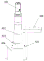
As shown in fig. 14, the endoscope guide camera module 414 includes a guide camera fixing plate 420 fixed to the table top 401, a camera fixing plate 423 attached to a side edge of the guide camera fixing plate 420, a first lens 422 inserted through the camera fixing plate, a first camera 421 disposed at one end of the first lens 422, a coaxial light source 424 disposed at the other end of the first lens 422, and an adjustment tilt shaft 425 disposed between the guide camera fixing plate 420 and the camera fixing plate 423.
As shown in fig. 15 and 16, the endoscope assembly 407 includes a first servo motor 406 fixed to the lead screw module 405, a rotating shaft 426 connected to the first servo motor 406, a U-shaped plate 427 provided on the rotating shaft 426, an endoscope joint 429 fixed to the U-shaped plate 427, a second camera 428 and a second lens 430 respectively connected to the upper and lower ends of the endoscope joint 429, a light guide column 431 perpendicular to the second lens 430, a light source connection column 433 connected to the lower end of the second lens 430, and two capillary seamless tubes 432 connected to the light source connection column 433.
The positioning mechanism 5 and the clogging detecting mechanism 6 are both conventional techniques.
The electrical system, control system and frame structure of the present apparatus are prior art and are therefore not shown.
The mechanical clamping arm takes the lattice out of the clamping table → places the lattice at the positioning component (the lattice is horizontally placed at the moment) → after positioning, the mechanical clamping arm clamps the lattice from the Z-axis direction → then rotates the lattice to the vertical direction from the horizontal direction → 56 the first face of the visual component detection lattice → rotates the mechanical clamping arm 180 ° → 56 the second face of the visual component detection lattice in the Z-axis direction → detection is completed → the mechanical clamping arm places the lattice at the positioning component (the lattice is horizontally placed at the moment) → the mechanical clamping arm rotates 90 ° in the horizontal direction to clamp the lattice → then rotates the lattice to the vertical direction from the horizontal direction → 56 the third face of the visual component detection lattice → rotates 180 ° → 56 the fourth face of the visual component detection lattice in the Z-axis direction → identifies the face with the lettering, and judges the direction;
the working process is as follows:
the mechanical clamping arm clamps the lattice with the recognized carved character faces onto the modified clamping assembly for positioning (the lattice is horizontally placed at the moment) → the mechanical clamping arm clamps the lattice from the horizontal direction → 36 the visual assembly is detected → the upper half of the area of the lattice 1/2 is detected → the mechanical clamping arm takes out the lattice → the mechanical clamping arm rotates 180 ° → 36 the visual assembly is detected along the Z-axis direction → the lower half of the area of the lattice 1/2 is detected → the mechanical clamping arm clamps the lattice on the detection table top → the mechanical clamping arm rotates the lattice 90 ° (the lattice is horizontally placed at the moment) → the mechanical clamping arm clamps the lattice from the horizontal direction → 36 the visual assembly is detected → the upper half of the remaining 1/2 lattice is detected → the mechanical clamping arm takes out the lattice → the mechanical clamping arm rotates 180 ° → 36 the visual assembly is detected → the lower half of the area of the lattice 1/2 is detected Measuring → the mechanical clamping arm clamps the grillwork detected at the station to the welding seam detection position for detection (if the sensor gives the material at the station, the mechanical clamping arm places the grillwork to the positioning assembly position for detection);
the method comprises the steps that a mechanical clamping arm clamps and places a lattice on a two-dimensional platform (simultaneously software preliminarily judges the number, types and positions of squares in the lattice), the sensors detect existence of materials, the two-dimensional platform moves to a fixed position, an endoscope guide camera assembly works, an algorithm calculates the offset of an X axis and a Y axis, the position offset of the two-dimensional platform movement adjusting lattice, the endoscope guide camera assembly works, the position of the lattice is corrected again, the displacement driving assembly drives the endoscope assembly to move downwards to start detecting a welding seam, the displacement driving assembly drives the endoscope assembly to move upwards, the two-dimensional platform moves to the next position to be detected simultaneously, the displacement driving assembly drives the endoscope assembly to move downwards to start detecting the welding seam, the welding seams in the same direction are all detected, the displacement driving assembly moves upwards, the rotating shaft rotates the endoscope assembly by 90 degrees, the two-dimensional platform moves to the first detection position to detect, and the second direction After all the weld joints are detected, the displacement driving assembly moves upwards → the rotating shaft rotates the endoscope assembly by 90 degrees (namely 180 degrees) again with the rotating shaft, the two-dimensional platform moves to the first detection position to start detection, after all the weld joints in the third direction are detected, the rotating shaft rotates the endoscope assembly by 90 degrees (namely 270 degrees) again with the rotating shaft, the two-dimensional platform moves to the first detection position to start detection, after all the weld joints in the fourth direction are detected, the mechanical clamping arm takes out the lattice clamp to rotate by 90 degrees along the horizontal plane, the lattice clamp is placed on the two-dimensional platform → the weld joints at the blocked part are clamped before detection → all the weld joints are detected, after the mechanical clamping arm takes out the lattice clamp to be placed on the clamping table, and the mechanical clamping arm completes all the actions.
The above-mentioned embodiment is only one of the preferred embodiments of the present invention, and should not be used to limit the scope of the present invention, and all the technical problems solved by the present invention should be consistent with the present invention, if they are not substantially modified or retouched in the spirit and concept of the present invention.
Claims (9)
1. The utility model provides an automatic detection device of grid work outward appearance of brazing, includes automatic feeding device (2), establishes and is used for the mechanical centre gripping arm (3) and the welding seam detection mechanism (4) of mechanical centre gripping arm (3) below that the centre gripping is detected grid work (1) by automatic feeding device (2) next door, its characterized in that:
the automatic feeding device (2) comprises a conveying trolley (205), a temporary storage (202) arranged on one side of the conveying trolley (205) and used for storing the grillwork, a conveying belt (204) arranged on the other side of the conveying trolley (205) and used for conveying trays (203) with the grillwork (1) placed on, and a clamping table (206) which is arranged on one end, close to the conveying trolley (205), of the conveying belt (204) and used for placing the grillwork to be detected and the checked grillwork;
the conveying trolley (205) comprises a guide rail (207) which is vertically arranged, a conveying platform (208) which is arranged on the guide rail (207) and can move up and down along the guide rail, and a driving mechanism which drives the conveying platform (208) to move along the guide rail (207), wherein a stretching plate which can slide left and right is arranged on the conveying platform (208); the guide rail (207) is fixedly arranged on a fixing frame (201) positioned at the upper end and the lower end of the guide rail;
one end of the conveying belt (204) is connected with a conveying table (208) in the conveying trolley (205), the conveying belt (204) and the conveying table (208) simultaneously slide up and down along a guide rail (207), and a clamping table (206) is fixedly arranged at the end of the conveying belt (204);
the mechanical clamping arm (3) comprises a support rod (301) which is fixedly arranged, a base (302) which is fixed on the support rod (301), a control arm (303) which is arranged on the base (302), a self-adaptive detection clamp (304) which is arranged at the end part of the control arm (303) and a controller (305) which is arranged on the base (302);
the control arm (303) comprises a connecting piece (306), a middle arm (307) and a front arm (308), the connecting piece (306) is rotatably connected with the base (302) and controlled by the controller (305) to rotate on the X axis, the middle arm (307) is rotatably connected with the connecting piece (306) and controlled by the controller (305) to swing on the Y axis, the front arm (308) is rotatably connected with the middle arm (307) and controlled by the controller (305) to swing on the Y axis, the self-adaptive detection clamp (304) is installed at the end part of the front arm (308) through a clamp connecting block (309), and the self-adaptive detection clamp (304) is controlled by the controller (305) to rotate on the clamp connecting block (309);
the welding seam detection mechanism (4) comprises a workbench panel (401), a two-dimensional platform (402) arranged on the workbench panel, a workpiece clamping part (403) arranged on the two-dimensional platform (402), a support frame (404) fixed on one side of the workbench panel (401), a screw rod module (405) connected with the support frame (404), an endoscope assembly (407) fixed on the screw rod module (405), an endoscope guide camera assembly (414) arranged at the bottom of the workbench panel (401) and matched with the endoscope assembly (407) relatively, and a displacement driving assembly arranged on the workbench panel (401), wherein the displacement driving assembly can drive the two-dimensional platform (402) to move along the transverse direction and the longitudinal direction;
the displacement driving assembly comprises a chain fixing plate (419) which is fixed on the workbench panel (401) and is arranged in parallel with the two-dimensional platform (402), a first chain (409) arranged in the chain fixing plate (419), a second chain (410) which is perpendicular to the first chain (409) and is connected with the two-dimensional platform (402), a second servo motor (408) which is fixedly arranged on the workbench panel (401) and is used for driving the first chain (409), a third servo motor (415) which is fixed on the workbench panel (401), a screw rod (416) which is connected with a bearing of the third servo motor (415) and is arranged in parallel with the first chain (409), and a screw rod nut (417) which is sleeved on the outer edge of the push-pull screw rod (416) and is used for rotating the two-dimensional platform (402) and moves along the direction of the screw rod (416).
2. The automated brazing grid appearance inspection device of claim 1, wherein: the workpiece clamping part (403) comprises a first dust cover (411) attached to the upper surface of the two-dimensional platform (402), a clamping fixing plate (434) fixed on the first dust cover (411), a fixing push plate (439) vertically arranged on the clamping fixing plate (434), a sliding push plate (412) attached to the clamping fixing plate (434), and a fourth motor (435) fixed on the clamping fixing plate (434) and used for pushing the sliding push plate (412) to advance, wherein a first rectangular hole (437) matched with the endoscope guide camera assembly (414) is formed in each of the clamping fixing plate (434) and the first dust cover (411), and a second dust cover (436) used for fixing a lead screw nut is arranged on the lower surface of the two-dimensional platform (402); and a second rectangular hole (438) matched with the first rectangular hole (437) is formed in the second dust cover (436).
3. The automated brazing grid appearance inspection device of claim 1, wherein: the endoscope guide camera assembly (414) comprises a guide camera fixing plate (420) fixed on a workbench panel (401), a camera fixing plate (423) arranged on the side edge of the guide camera fixing plate (420), a first lens (422) penetrating through the camera fixing plate, a first camera (421) arranged at one end part of the first lens (422), a coaxial light source (424) arranged at the other end part of the first lens (422), and an adjusting pitch shaft (425) arranged between the guide camera fixing plate (420) and the camera fixing plate (423).
4. The automated brazing grid appearance inspection device of claim 1, wherein: the endoscope assembly (407) comprises a first servo motor (406) fixed on the screw rod module (405), a rotating shaft (426) connected with the first servo motor (406), a U-shaped plate (427) arranged on the rotating shaft (426), an endoscope joint (429) fixed on the U-shaped plate (427), a second camera (428) and a second lens (430) which are respectively connected with the upper end and the lower end of the endoscope joint (429), a light guide column (431) perpendicular to the second lens (430), a light source connecting column (433) connected with the lower end of the second lens (430), and two capillary seamless tubes (432) connected with the light source connecting column (433).
5. The automated brazing grid appearance inspection device of claim 1, wherein: the driving mechanism in the conveying trolley (205) comprises a driving motor (209), a gear set (210) and a conveying belt (211), wherein the conveying belt (211) is connected with the conveying table (208), the conveying belt (211) is wound on the outer side of the gear set (210), the inner side of the conveying belt (211) is meshed with the gear set (210), the gear set (210) comprises an upper group of gears and a lower group of gears, the upper group of gears and the lower group of gears are respectively fixed on the fixing frames (201) at the upper end and the lower end, and the driving motor (209) drives the gear set at the upper end or the lower end to.
6. The automated brazing grid appearance inspection device of claim 1, wherein: press from both sides and get platform (206) including locating landing leg (212) of transmission band (204) both sides and fixing mounting panel (213) on landing leg (212), mounting panel (213) on be equipped with rotary mechanism, rotary mechanism on be equipped with the tray and place frame (214), tray (203) are placed on the tray places frame (214).
7. The automated brazing grid appearance inspection device of claim 6, wherein: the rotating mechanism comprises a rotating cylinder (215) arranged on a clamping table mounting plate (213) and a rotating column (216) connected with the rotating cylinder (215), the upper end of the rotating column (216) is connected with a tray placing frame (214), the two tray placing frames (214) are arranged in a back-to-back mode, the two tray placing frames (214) are respectively used for placing a grillwork to be detected and a checked grillwork, and the rotating column (216) can swing at least 180 degrees in the back-to-back mode under the driving of the rotating cylinder (215).
8. The automated brazing grid appearance inspection device of claim 1, wherein: the self-adaptive detection clamp (304) in the mechanical clamping arm (3) comprises a clamping cylinder (3041), and a fixed clamping arm (3042) and a self-adaptive clamping arm (3043) which are connected with the clamping cylinder (3041) and are arranged oppositely; the grillwork (1) is positioned between the fixed clamping arm (3042) and the self-adaptive clamping arm (3043), and the clamping cylinder (3041) is driven to enable the grillwork (1) to be clamped.
9. The automated brazing grid appearance inspection device of claim 8, wherein: the self-adaptive clamping arm (3043) comprises a clamping plate connecting block (3044), a middle adaptive rod (3045), an upper clamping piece (3046) and a lower clamping piece (3047), wherein the clamping plate connecting block (3044) is L-shaped, a panel at one end is fixedly arranged on a sliding head of a clamping cylinder (3041), the middle adaptive rod (3045) is arranged in a panel at the other end, the upper clamping piece (3046) and the lower clamping piece (3047) are respectively arranged at two ends of the middle adaptive rod (3045), the middle part of the middle adaptive rod (3045) is hinged with the clamping plate connecting block, and the upper clamping piece (3046) and the lower clamping piece (3047) are respectively hinged with the end part of the middle adaptive rod (3045).
Priority Applications (1)
| Application Number | Priority Date | Filing Date | Title |
|---|---|---|---|
| CN201711457773.2A CN109975302B (en) | 2017-12-28 | 2017-12-28 | Automatic detection device of grillwork outward appearance of brazing |
Applications Claiming Priority (1)
| Application Number | Priority Date | Filing Date | Title |
|---|---|---|---|
| CN201711457773.2A CN109975302B (en) | 2017-12-28 | 2017-12-28 | Automatic detection device of grillwork outward appearance of brazing |
Publications (2)
| Publication Number | Publication Date |
|---|---|
| CN109975302A CN109975302A (en) | 2019-07-05 |
| CN109975302B true CN109975302B (en) | 2021-06-18 |
Family
ID=67074505
Family Applications (1)
| Application Number | Title | Priority Date | Filing Date |
|---|---|---|---|
| CN201711457773.2A Active CN109975302B (en) | 2017-12-28 | 2017-12-28 | Automatic detection device of grillwork outward appearance of brazing |
Country Status (1)
| Country | Link |
|---|---|
| CN (1) | CN109975302B (en) |
Families Citing this family (3)
| Publication number | Priority date | Publication date | Assignee | Title |
|---|---|---|---|---|
| CN110672811A (en) * | 2019-10-21 | 2020-01-10 | 远大可建科技有限公司 | Core plate inner cavity detection device and method |
| CN111077081B (en) * | 2020-01-21 | 2022-06-07 | 重庆长安汽车股份有限公司 | Endoscope uses protection device |
| CN111551550A (en) * | 2020-06-13 | 2020-08-18 | 深圳市宏毅泰科技有限公司 | Full-automatic test equipment |
Citations (11)
| Publication number | Priority date | Publication date | Assignee | Title |
|---|---|---|---|---|
| EP0076498A2 (en) * | 1981-10-07 | 1983-04-13 | Messer Griesheim Gmbh | A method controlling an arc welding torch of a welding robot |
| JPH05208290A (en) * | 1992-01-31 | 1993-08-20 | Amada Co Ltd | Assisting gas injection controller for laser beam welding equipment |
| CN102189366A (en) * | 2010-03-01 | 2011-09-21 | 株式会社神户制钢所 | Clamping confirming system, welding robot system, clamping tool control device and clamping confirming method |
| CN202956314U (en) * | 2012-11-30 | 2013-05-29 | 慈溪市宏晟机械设备有限公司 | Argon welding fastness detector |
| CN103273490A (en) * | 2013-05-30 | 2013-09-04 | 青岛博智达自动化技术有限公司 | Industrial robot for welding |
| CN203449313U (en) * | 2013-12-06 | 2014-02-26 | 青岛博智达自动化技术有限公司 | Industrial robot used for welding |
| CN104015199A (en) * | 2014-05-29 | 2014-09-03 | 中广核检测技术有限公司 | Mechanical arm and detection robot based on mechanical arms |
| CN205749314U (en) * | 2015-12-31 | 2016-11-30 | 中核建中核燃料元件有限公司 | A kind of AFA3G grid spacer outward appearance automatic detection device |
| CN206200303U (en) * | 2016-08-24 | 2017-05-31 | 河北亿鑫通讯设备有限公司 | A kind of intelligent tower boots welder |
| CN106990111A (en) * | 2015-12-01 | 2017-07-28 | 通用电气公司 | For in the process to the system of the automatic inspection of weld seam |
| CA2941153C (en) * | 2014-03-17 | 2018-06-05 | Bombardier Transportation Gmbh | Hybrid laser welding system and method using two robots |
-
2017
- 2017-12-28 CN CN201711457773.2A patent/CN109975302B/en active Active
Patent Citations (11)
| Publication number | Priority date | Publication date | Assignee | Title |
|---|---|---|---|---|
| EP0076498A2 (en) * | 1981-10-07 | 1983-04-13 | Messer Griesheim Gmbh | A method controlling an arc welding torch of a welding robot |
| JPH05208290A (en) * | 1992-01-31 | 1993-08-20 | Amada Co Ltd | Assisting gas injection controller for laser beam welding equipment |
| CN102189366A (en) * | 2010-03-01 | 2011-09-21 | 株式会社神户制钢所 | Clamping confirming system, welding robot system, clamping tool control device and clamping confirming method |
| CN202956314U (en) * | 2012-11-30 | 2013-05-29 | 慈溪市宏晟机械设备有限公司 | Argon welding fastness detector |
| CN103273490A (en) * | 2013-05-30 | 2013-09-04 | 青岛博智达自动化技术有限公司 | Industrial robot for welding |
| CN203449313U (en) * | 2013-12-06 | 2014-02-26 | 青岛博智达自动化技术有限公司 | Industrial robot used for welding |
| CA2941153C (en) * | 2014-03-17 | 2018-06-05 | Bombardier Transportation Gmbh | Hybrid laser welding system and method using two robots |
| CN104015199A (en) * | 2014-05-29 | 2014-09-03 | 中广核检测技术有限公司 | Mechanical arm and detection robot based on mechanical arms |
| CN106990111A (en) * | 2015-12-01 | 2017-07-28 | 通用电气公司 | For in the process to the system of the automatic inspection of weld seam |
| CN205749314U (en) * | 2015-12-31 | 2016-11-30 | 中核建中核燃料元件有限公司 | A kind of AFA3G grid spacer outward appearance automatic detection device |
| CN206200303U (en) * | 2016-08-24 | 2017-05-31 | 河北亿鑫通讯设备有限公司 | A kind of intelligent tower boots welder |
Also Published As
| Publication number | Publication date |
|---|---|
| CN109975302A (en) | 2019-07-05 |
Similar Documents
| Publication | Publication Date | Title |
|---|---|---|
| CN107116801B (en) | Automatic welding machine for cross-flow fan blades | |
| CN107639038B (en) | Automatic detection platform for product flaws | |
| CN108098196B (en) | Automatic production line for assembling and welding of breaker robot | |
| CN109975302B (en) | Automatic detection device of grillwork outward appearance of brazing | |
| CN203649647U (en) | Double-station dual-lens elevation type welding platform | |
| CN209125127U (en) | A kind of laser cutting welder | |
| CN109724521A (en) | A kind of automatic marking grading dispensing solidification equipment and its detection mark packing production chain | |
| CN206216158U (en) | A kind of double hopper type elevator hopper automatic welder | |
| CN108817783B (en) | Welding equipment | |
| CN113414561A (en) | Automatic assembly system for straight pipe flange for welding before bending | |
| CN110498244A (en) | Long handle bevel gear finishing automatic assembly line | |
| CN113275707A (en) | Automatic arc welding equipment and welding method | |
| CN211276895U (en) | Automatic welding production system for net rack connecting rod | |
| CN111060017A (en) | Single polycrystalline silicon rod automatic checkout device | |
| CN208276425U (en) | A kind of automatic welding machine | |
| CN110434019A (en) | A kind of automatic dispensing device for tablet computer | |
| CN107838570A (en) | A kind of Pseudobulbus Bletillae (Rhizoma Bletillae) automatic assembly line and production line control method | |
| CN117415520A (en) | Soft copper wire welding production line of movable contact | |
| CN209125128U (en) | A kind of laser cutting device | |
| CN207563951U (en) | A kind of Pseudobulbus Bletillae (Rhizoma Bletillae) automatic assembly line | |
| CN116511835A (en) | Barrel automatic processing system, barrel processing method and barrel automatic processing technology | |
| CN202726275U (en) | Heavy-calibre elbow longitudinal seam automatic welding device | |
| CN214109333U (en) | Four-axis welding machine | |
| CN206296720U (en) | Self-feeding and reclaimer device | |
| CN115635214A (en) | Box type component inner partition plate assembling device |
Legal Events
| Date | Code | Title | Description |
|---|---|---|---|
| PB01 | Publication | ||
| PB01 | Publication | ||
| SE01 | Entry into force of request for substantive examination | ||
| SE01 | Entry into force of request for substantive examination | ||
| GR01 | Patent grant | ||
| GR01 | Patent grant |