WO2019208018A1 - 電池温調装置 - Google Patents
電池温調装置 Download PDFInfo
- Publication number
- WO2019208018A1 WO2019208018A1 PCT/JP2019/010918 JP2019010918W WO2019208018A1 WO 2019208018 A1 WO2019208018 A1 WO 2019208018A1 JP 2019010918 W JP2019010918 W JP 2019010918W WO 2019208018 A1 WO2019208018 A1 WO 2019208018A1
- Authority
- WO
- WIPO (PCT)
- Prior art keywords
- heat
- secondary battery
- battery
- control device
- cooling water
- Prior art date
- Legal status (The legal status is an assumption and is not a legal conclusion. Google has not performed a legal analysis and makes no representation as to the accuracy of the status listed.)
- Ceased
Links
Images


Classifications
-
- H—ELECTRICITY
- H01—ELECTRIC ELEMENTS
- H01M—PROCESSES OR MEANS, e.g. BATTERIES, FOR THE DIRECT CONVERSION OF CHEMICAL ENERGY INTO ELECTRICAL ENERGY
- H01M10/00—Secondary cells; Manufacture thereof
- H01M10/60—Heating or cooling; Temperature control
- H01M10/61—Types of temperature control
- H01M10/613—Cooling or keeping cold
-
- H—ELECTRICITY
- H01—ELECTRIC ELEMENTS
- H01M—PROCESSES OR MEANS, e.g. BATTERIES, FOR THE DIRECT CONVERSION OF CHEMICAL ENERGY INTO ELECTRICAL ENERGY
- H01M10/00—Secondary cells; Manufacture thereof
- H01M10/60—Heating or cooling; Temperature control
- H01M10/61—Types of temperature control
- H01M10/615—Heating or keeping warm
-
- H—ELECTRICITY
- H01—ELECTRIC ELEMENTS
- H01M—PROCESSES OR MEANS, e.g. BATTERIES, FOR THE DIRECT CONVERSION OF CHEMICAL ENERGY INTO ELECTRICAL ENERGY
- H01M10/00—Secondary cells; Manufacture thereof
- H01M10/60—Heating or cooling; Temperature control
- H01M10/62—Heating or cooling; Temperature control specially adapted for specific applications
- H01M10/625—Vehicles
-
- H—ELECTRICITY
- H01—ELECTRIC ELEMENTS
- H01M—PROCESSES OR MEANS, e.g. BATTERIES, FOR THE DIRECT CONVERSION OF CHEMICAL ENERGY INTO ELECTRICAL ENERGY
- H01M10/00—Secondary cells; Manufacture thereof
- H01M10/60—Heating or cooling; Temperature control
- H01M10/63—Control systems
- H01M10/637—Control systems characterised by the use of reversible temperature-sensitive devices, e.g. NTC, PTC or bimetal devices; characterised by control of the internal current flowing through the cells, e.g. by switching
-
- H—ELECTRICITY
- H01—ELECTRIC ELEMENTS
- H01M—PROCESSES OR MEANS, e.g. BATTERIES, FOR THE DIRECT CONVERSION OF CHEMICAL ENERGY INTO ELECTRICAL ENERGY
- H01M10/00—Secondary cells; Manufacture thereof
- H01M10/60—Heating or cooling; Temperature control
- H01M10/65—Means for temperature control structurally associated with the cells
- H01M10/655—Solid structures for heat exchange or heat conduction
- H01M10/6552—Closed pipes transferring heat by thermal conductivity or phase transition, e.g. heat pipes
-
- H—ELECTRICITY
- H01—ELECTRIC ELEMENTS
- H01M—PROCESSES OR MEANS, e.g. BATTERIES, FOR THE DIRECT CONVERSION OF CHEMICAL ENERGY INTO ELECTRICAL ENERGY
- H01M10/00—Secondary cells; Manufacture thereof
- H01M10/60—Heating or cooling; Temperature control
- H01M10/65—Means for temperature control structurally associated with the cells
- H01M10/655—Solid structures for heat exchange or heat conduction
- H01M10/6556—Solid parts with flow channel passages or pipes for heat exchange
-
- H—ELECTRICITY
- H01—ELECTRIC ELEMENTS
- H01M—PROCESSES OR MEANS, e.g. BATTERIES, FOR THE DIRECT CONVERSION OF CHEMICAL ENERGY INTO ELECTRICAL ENERGY
- H01M10/00—Secondary cells; Manufacture thereof
- H01M10/60—Heating or cooling; Temperature control
- H01M10/65—Means for temperature control structurally associated with the cells
- H01M10/656—Means for temperature control structurally associated with the cells characterised by the type of heat-exchange fluid
- H01M10/6567—Liquids
- H01M10/6568—Liquids characterised by flow circuits, e.g. loops, located externally to the cells or cell casings
-
- H—ELECTRICITY
- H01—ELECTRIC ELEMENTS
- H01M—PROCESSES OR MEANS, e.g. BATTERIES, FOR THE DIRECT CONVERSION OF CHEMICAL ENERGY INTO ELECTRICAL ENERGY
- H01M10/00—Secondary cells; Manufacture thereof
- H01M10/60—Heating or cooling; Temperature control
- H01M10/65—Means for temperature control structurally associated with the cells
- H01M10/658—Means for temperature control structurally associated with the cells by thermal insulation or shielding
-
- H—ELECTRICITY
- H01—ELECTRIC ELEMENTS
- H01M—PROCESSES OR MEANS, e.g. BATTERIES, FOR THE DIRECT CONVERSION OF CHEMICAL ENERGY INTO ELECTRICAL ENERGY
- H01M10/00—Secondary cells; Manufacture thereof
- H01M10/60—Heating or cooling; Temperature control
- H01M10/66—Heat-exchange relationships between the cells and other systems, e.g. central heating systems or fuel cells
- H01M10/667—Heat-exchange relationships between the cells and other systems, e.g. central heating systems or fuel cells the system being an electronic component, e.g. a CPU, an inverter or a capacitor
-
- H—ELECTRICITY
- H02—GENERATION; CONVERSION OR DISTRIBUTION OF ELECTRIC POWER
- H02M—APPARATUS FOR CONVERSION BETWEEN AC AND AC, BETWEEN AC AND DC, OR BETWEEN DC AND DC, AND FOR USE WITH MAINS OR SIMILAR POWER SUPPLY SYSTEMS; CONVERSION OF DC OR AC INPUT POWER INTO SURGE OUTPUT POWER; CONTROL OR REGULATION THEREOF
- H02M7/00—Conversion of AC power input into DC power output; Conversion of DC power input into AC power output
- H02M7/42—Conversion of DC power input into AC power output without possibility of reversal
- H02M7/44—Conversion of DC power input into AC power output without possibility of reversal by static converters
- H02M7/48—Conversion of DC power input into AC power output without possibility of reversal by static converters using discharge tubes with control electrode or semiconductor devices with control electrode
-
- Y—GENERAL TAGGING OF NEW TECHNOLOGICAL DEVELOPMENTS; GENERAL TAGGING OF CROSS-SECTIONAL TECHNOLOGIES SPANNING OVER SEVERAL SECTIONS OF THE IPC; TECHNICAL SUBJECTS COVERED BY FORMER USPC CROSS-REFERENCE ART COLLECTIONS [XRACs] AND DIGESTS
- Y02—TECHNOLOGIES OR APPLICATIONS FOR MITIGATION OR ADAPTATION AGAINST CLIMATE CHANGE
- Y02E—REDUCTION OF GREENHOUSE GAS [GHG] EMISSIONS, RELATED TO ENERGY GENERATION, TRANSMISSION OR DISTRIBUTION
- Y02E60/00—Enabling technologies; Technologies with a potential or indirect contribution to GHG emissions mitigation
- Y02E60/10—Energy storage using batteries
Definitions
- the present disclosure relates to a battery temperature control device.
- Patent Document 1 a technique for generating a large current in a secondary battery whose output has been significantly reduced by repeatedly charging and discharging the secondary battery using an external circuit and raising the temperature by self-heating due to the internal resistance of the secondary battery is, for example, This is proposed in Patent Document 1.
- This disclosure aims to provide a battery temperature control device that can suppress heat dissipation loss due to a ripple temperature increase of a secondary battery.
- the battery temperature control apparatus is an apparatus that self-heats a secondary battery by a ripple current flowing in the secondary battery by controlling charge / discharge of the chargeable / dischargeable secondary battery. .
- the battery temperature control device includes a heat insulating portion that is disposed outside the secondary battery and insulates heat released from the secondary battery.
- the battery temperature control device includes a heat storage unit that stores heat released from the secondary battery.
- the heat of the secondary battery is stored in the heat storage part and is difficult to escape to the external environment, and the heat energy once stored can be used in the secondary battery and other devices. Therefore, it is possible to suppress heat dissipation loss due to ripple temperature rise of the secondary battery.
- the battery temperature control device includes a current generator and a heat medium circuit.
- the current generator controls the charge / discharge of the chargeable / dischargeable secondary battery to self-heat the secondary battery by the ripple current flowing through the secondary battery.
- the heat medium circuit circulates the heat medium and receives heat generated by the current generator with the heat medium.
- the heat generated by the current generator is transferred to the heat medium circuit, the heat generated to generate the ripple current can be used in the heat medium circuit. Therefore, it is possible to suppress heat dissipation loss due to ripple temperature rise of the secondary battery.
- FIG. 1 is a diagram showing a battery temperature control device according to the first embodiment.
- FIG. 2 is a circuit diagram of the inverter.
- FIG. 3 is a diagram for explaining a control device included in the battery temperature control device,
- FIG. 4 is a diagram for explaining the effect of the heat insulating portion.
- FIG. 5 is a diagram illustrating a secondary battery according to the second embodiment.
- FIG. 6 is a diagram illustrating a secondary battery according to the third embodiment.
- FIG. 7 is a view showing a part of the battery temperature control device according to the fourth embodiment, FIG.
- FIG. 8 is a diagram illustrating an inverter driving method according to the fourth embodiment.
- FIG. 9 is a view showing a part of the battery temperature control device according to the fifth embodiment
- FIG. 10 is a diagram showing a part of the battery temperature control device according to the sixth embodiment
- FIG. 11 is a diagram showing a battery temperature control device according to the seventh embodiment.
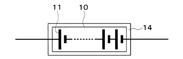
- a battery temperature control device 1 shown in FIG. 1 is a device that adjusts a secondary battery 10 mounted on a vehicle to an appropriate temperature.
- the battery temperature control device 1 is a device that self-heats the secondary battery 10 by a ripple current flowing through the secondary battery 10 by controlling charging and discharging of the secondary battery 10.
- the battery temperature control device 1 also functions as an air conditioner that adjusts the interior space of the vehicle to an appropriate temperature.
- the battery temperature control device 1 is mounted on an electric vehicle that obtains a driving force for driving a vehicle from an electric motor for driving.
- the electric vehicle can charge the secondary battery 10 mounted on the vehicle with electric power supplied from an external power source when the vehicle is stopped.
- the external power source is, for example, a commercial power source.
- the electric power stored in the secondary battery 10 is supplied not only to the electric motor for traveling but also to various in-vehicle devices including the electric components constituting the battery temperature control device 1.
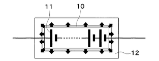
- the secondary battery 10 has a plurality of chargeable / dischargeable battery cells 11.
- a lithium ion battery can be used, for example.
- this type of battery is at a low temperature, the chemical reaction is difficult to proceed, and sufficient performance with respect to charging and discharging cannot be exhibited.
- this type of battery is likely to deteriorate at a high temperature. Therefore, the temperature of each battery cell 11 is adjusted within an appropriate temperature range that can exhibit sufficient performance.
- the battery temperature control apparatus 1 has a heat insulating part 12 for insulating heat released from the secondary battery 10.
- a material such as a vacuum heat insulating material, glass wool, or polyurethane foam is used as the heat insulating portion 12.
- the heat insulating part 12 is disposed outside the secondary battery 10.
- the heat insulating part 12 covers a part or the whole of the secondary battery 10.
- the wiring penetrates the heat insulating portion 12.
- the battery temperature control device 1 has a refrigeration cycle device 20.
- each component apparatus which comprises the refrigerating-cycle apparatus 20 is demonstrated.
- Compressor 21 draws in refrigerant in refrigeration cycle apparatus 20, compresses it, and discharges it.
- the compressor 21 is arrange
- the compressor 21 is an electric compressor that rotationally drives a fixed capacity type compression mechanism with a fixed discharge capacity by an electric motor.
- the rotation speed (that is, the refrigerant discharge capacity) of the compressor 21 is controlled by a control signal output from the control device 70 described later.
- the inlet side of the refrigerant passage of the high temperature side water-refrigerant heat exchanger 22 is connected to the discharge port of the compressor 21.
- the high temperature side water-refrigerant heat exchanger 22 heat-exchanges the high pressure refrigerant discharged from the compressor 21 and the high temperature side heat medium circulating in the high temperature cooling water circuit 30 to heat the high temperature side heat medium. It is.
- As the high temperature side heat medium a solution containing ethylene glycol, an antifreeze solution, or the like can be used.
- the high-temperature cooling water circuit 30 is a high-temperature side water circuit that circulates the high-temperature side heat medium.
- the high temperature coolant circuit 30 has a high temperature side circulation channel 31.
- the high temperature side circulation channel 31 is a cooling water channel through which high temperature side cooling water circulates as a high temperature side heat medium.
- a water passage of the high temperature side water-refrigerant heat exchanger 22, a high temperature side radiator 32, a high temperature side pump 33, a high temperature side electric heater 34, a high temperature side heater core 35, and the like are arranged.
- the high temperature side radiator 32 is arranged on the front side in the vehicle bonnet.
- the high temperature side radiator 32 may be formed integrally with the high temperature side water-refrigerant heat exchanger 22 or the like.
- the high temperature side radiator 32 exchanges heat between the high temperature side heat medium heated by the high temperature side water-refrigerant heat exchanger 22 and the outside air blown from an outside air fan (not shown), and the heat of the high temperature side heat medium is transferred to the outside air. It is a heat exchanger that dissipates heat.
- the high temperature side pump 33 is a high temperature side water pump that pumps the high temperature side heat medium to the high temperature side electric heater 34 in the high temperature cooling water circuit 30.
- the high temperature side pump 33 is an electric pump in which the rotation speed (that is, the water pressure feeding capacity) is controlled by the control voltage output from the control device 70.
- the high temperature side electric heater 34 is an auxiliary heater that generates heat when electric power is supplied and heats the high temperature side heat medium of the high temperature cooling water circuit 30 that is pumped from the high temperature side pump 33.
- the high temperature side heater core 35 is disposed in an air conditioning casing which will be described later.
- the high temperature side heater core 35 is a heat exchanger that heats the blown air by exchanging heat between the high temperature side heat medium heated by the high temperature side electric heater 34 and the blown air.
- the high temperature side pump 33, the high temperature side electric heater 34, the high temperature side heater core 35, the high temperature side water-refrigerant heat exchanger 22 and the like disposed in the high temperature cooling water circuit 30 are discharged from the compressor 21.
- a heating unit is configured to heat the blown air using the refrigerant as a heat source.
- the high temperature cooling water circuit 30 has a path connected in parallel to the high temperature side radiator 32.
- the path connected in parallel to the high temperature side radiator 32 is a detour path that bypasses the high temperature side radiator 32.
- a thermostat valve (not shown) is provided at a branch point between the bypass path and the path of the high-temperature side radiator 32. Accordingly, the high temperature side heat medium flows through the path of the high temperature side radiator 32 or the detour path according to the temperature of the high temperature side heat medium of the high temperature cooling water circuit 30.
- the outlet side of the branch portion 23 a is connected to the outlet of the refrigerant passage of the high temperature side water-refrigerant heat exchanger 22.
- the branch portion 23a branches the refrigerant flow that has flowed out of the high-temperature side water-refrigerant heat exchanger 22.
- the branch part 23a has a three-way joint structure with three inflow / outflow ports communicating with each other. In the branch portion 23a, one of the three inlets and outlets is a refrigerant inflow port, and the remaining two are refrigerant outlets.
- a receiver may be connected to the outlet of the refrigerant passage of the high temperature side water-refrigerant heat exchanger 22.
- the receiver separates the gas-liquid of the high-pressure refrigerant that has flowed out of the high-temperature water-refrigerant heat exchanger 22 and causes the separated liquid-phase refrigerant to flow downstream, and stores the excess refrigerant in the cycle as the liquid-phase refrigerant. It is a separation part.
- the receiver is a bottomed cylindrical container.
- the receiver may be formed integrally with the high temperature side water-refrigerant heat exchanger 22 or the like.
- the inlet side of the cooling expansion valve 24a is connected to one outlet of the branch portion 23a.
- An inlet side of the endothermic expansion valve 24b is connected to the other outlet of the branch portion 23a.
- the cooling expansion valve 24a is a pressure reducing unit that depressurizes the refrigerant flowing out of the high-temperature side water-refrigerant heat exchanger 22 at least in the cooling mode and the dehumidifying heating mode, and controls the flow rate of the refrigerant flowing into the indoor evaporator 25. This is a cooling flow rate adjusting unit to be adjusted.
- the cooling expansion valve 24a is an electric variable throttle mechanism that includes a valve body that can change the throttle opening degree and an electric actuator that changes the opening degree of the valve body.
- the electric actuator is a stepping motor.
- the operation of the cooling expansion valve 24 a is controlled by a control signal output from the control device 70.
- the control signal is, for example, a control pulse.
- the cooling expansion valve 24a has a fully closed function of closing the refrigerant passage by closing the valve opening degree.
- the refrigerant inlet side of the indoor evaporator 25 is connected to the outlet of the cooling expansion valve 24a.
- the indoor evaporator 25 is disposed in the air conditioning casing. More specifically, the indoor evaporator 25 is disposed on the upstream side of the blowing air flow with respect to the high temperature side heater core 35.
- the indoor evaporator 25 is a cooling unit that heat-exchanges the low-pressure refrigerant decompressed by the cooling expansion valve 24a and the blown air to evaporate the low-pressure refrigerant and cool the blown air at least in the cooling mode and the dehumidifying heating mode. It is an evaporation part.
- the inlet side of the evaporation pressure adjusting valve 26 is connected to the refrigerant outlet of the indoor evaporator 25.
- the evaporation pressure adjusting valve 26 is an evaporation pressure adjusting unit that maintains the refrigerant evaporation pressure in the indoor evaporator 25 at or above a predetermined reference pressure.
- the evaporation pressure adjusting valve 26 is configured by a mechanical variable throttle mechanism that increases the valve opening as the refrigerant pressure on the outlet side of the indoor evaporator 25 increases.
- an evaporating pressure adjusting valve 26 that maintains the refrigerant evaporating temperature in the indoor evaporator 25 at or above a reference temperature capable of suppressing frost formation in the indoor evaporator 25 is employed.
- the reference temperature is 1 ° C., for example.
- the outlet of the evaporation pressure adjusting valve 26 is connected to one inlet side of the merging portion 23b.
- the junction 23 b joins the refrigerant flow that has flowed out of the evaporation pressure adjusting valve 26 and the refrigerant flow that has flowed out of the chiller 27.
- the basic configuration of the merging portion 23b is the same as that of the branching portion 23a. That is, the merge part has a three-way joint structure. Two of the three inlets and outlets are refrigerant inlets, and the remaining one is a refrigerant outlet.
- the endothermic expansion valve 24b is a pressure reducing unit that depressurizes the refrigerant that has flowed out of the high-temperature side water-refrigerant heat exchanger 22 at least in the heating mode, and also adjusts the flow rate of the refrigerant that flows into the chiller 27. It is.
- the basic configuration of the endothermic expansion valve 24b is the same as that of the cooling expansion valve 24a.
- the inlet side of the refrigerant passage of the chiller 27 is connected to the outlet of the endothermic expansion valve 24b.
- the chiller 27 exchanges heat between the low-pressure refrigerant decompressed by the endothermic expansion valve 24b and the low-temperature side heat medium circulating in the low-temperature cooling water circuit 40 at least in the heating mode, evaporates the low-pressure refrigerant, and absorbs heat to the refrigerant.
- a solution containing ethylene glycol, an antifreeze solution, or the like can be used as the low-temperature heat medium.
- the refrigerant circuit formed by the refrigeration cycle apparatus 20 is a heat pump circuit 28 that draws heat from the low-temperature cooling water circuit 40 on the low temperature side to the refrigerant circuit on the high temperature side by circulating the refrigerant. That is, the heat of the cooling water circulating through the low-temperature cooling water circuit 40 is transferred to the refrigerant circulating through the heat pump circuit 28.
- the chiller 27 absorbs heat from the cooling water to the refrigerant. Thus, the heat of the cooling water is transferred from the low-temperature cooling water circuit 40 to the heat pump circuit 28 via the chiller 27.
- the other inlet side of the merging portion 23b is connected to the outlet of the refrigerant passage of the chiller 27.
- the suction port side of the compressor 21 is connected to the outlet of the junction 23b.
- the low-temperature cooling water circuit 40 is a low-temperature side water circuit for circulating the low-temperature side heat medium.
- the low temperature cooling water circuit 40 includes a low temperature side circulation channel 41 and a battery channel 42.
- the low temperature side circulation channel 41 is a channel through which low temperature side cooling water circulates as a low temperature side heat medium.
- a low temperature side pump 43, a chiller 27, a low temperature side electric heater 44, an inverter 45, a motor generator 46, and a low temperature side radiator 47 are arranged in the low temperature side circulation passage 41.
- the low temperature side pump 43 is a low temperature side water pump that pumps the low temperature side heat medium to the inlet side of the water passage of the chiller 27 in the low temperature cooling water circuit 40.
- the basic configuration of the low temperature side pump 43 is the same as that of the high temperature side pump 33.
- the low temperature side electric heater 44 is an auxiliary heater that generates heat when electric power is supplied and heats the cooling water of the low temperature cooling water circuit 40.
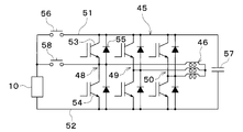
- the inverter 45 is a power conversion device that converts DC power supplied from the secondary battery 10 into AC power and outputs the AC power to the motor generator 46.
- the motor generator 46 uses the electric power output from the inverter 45 to generate a driving force for traveling and also generates regenerative electric power during deceleration or downhill.
- the inverter 45 and the motor generator 46 are adjusted by the cooling water of the low-temperature cooling water circuit 40 within an appropriate temperature range in which sufficient performance can be exhibited.
- the motor generator 46 is a three-phase rotating machine in which, for example, three coils of a U phase, a V phase, and a W phase are connected at a neutral point. Terminals that are not on the neutral point side of the motor generator 46 are connected to the secondary battery 10 via the inverter 45.
- the inverter 45 generates a three-phase AC voltage and current of U phase, V phase, and W phase to drive the high voltage motor generator 46. Therefore, inverter 45 has U-phase arm 48, V-phase arm 49, and W-phase arm 50. These arms 48 to 50 are connected in parallel between the positive electrode side wiring 51 and the negative electrode side wiring 52.
- Each arm 48 to 50 has two switching elements 53 and 54 connected in series.
- the first switching element 53 is connected to the positive electrode side wiring 51.
- the second switching element 54 is connected between the first switching element 53 and the negative electrode side wiring 52.
- a diode 55 is connected between the collector and emitter of each of the switching elements 53 and 54 to allow current to flow from the emitter side to the collector side.
- the connection points of the switching elements 53 and 54 are connected to the terminals of the motor generator 46.
- Each of the switching elements 53 and 54 is, for example, an IGBT (Insulated Gate Gate Bipolar Transistor).
- Each diode 55 is an FWD (Free Wheeling Diode).
- the positive electrode of the secondary battery 10 is connected to the positive electrode side wiring 51 of the inverter 45 through the relay 56. Further, a smoothing capacitor 57 is connected between the positive electrode side wiring 51 and the negative electrode side wiring 52 of the inverter 45.
- the positive electrode of the secondary battery 10 is connected via a relay 58 to a connection point of the switching elements 53 and 54 corresponding to the U phase.
- the relays 56 and 58 for example, movable contact type electromagnetic relays are used.
- the switching elements 53 and 54 and the relays 56 and 58 are electronically operated by an operation signal from a control device 70 described later.
- the low temperature side radiator 47 is formed integrally with the chiller 27 and the like, and is disposed on the front side in the vehicle bonnet.
- the low temperature side radiator 47 is a heat exchanger that exchanges heat between the low temperature side heat medium cooled by the chiller 27 and the outside air blown from the outside air fan, and causes the low temperature side heat medium to absorb heat from the outside air.
- the low-temperature cooling water circuit 40 has a path connected in parallel to the low-temperature side radiator 47.
- the path connected in parallel to the low temperature side radiator 47 is a detour path that bypasses the low temperature side radiator 47.
- a thermostat valve (not shown) is provided at a branch point between the bypass path and the path of the low-temperature side radiator 47. Accordingly, the low temperature side heat medium flows through the path of the low temperature side radiator 47 or the detour path according to the temperature of the low temperature side heat medium of the low temperature cooling water circuit 40.
- a first three-way valve 59 and a second three-way valve 60 are arranged at a connection portion between the low temperature side circulation channel 41 and the battery channel 42.
- the first three-way valve 59 is an electromagnetic valve that switches between a state in which the cooling water of the low-temperature side circulation passage 41 flows into the battery passage 42 and a state in which the cooling water does not flow into the battery passage 42.
- the second three-way valve 60 is an electromagnetic valve that switches between a state in which the cooling water in the battery passage 42 flows out to the low temperature side circulation passage 41 and a state in which it does not flow out. Therefore, it can be said that the low-temperature cooling water circuit 40 is a heat medium circuit that receives the heat of the secondary battery 10 with the cooling water that is the heat medium.
- the refrigerant circuit formed by the refrigeration cycle apparatus 20 can be said to be a heat medium circuit that receives the heat of the cooling water with the refrigerant that is the heat medium via the chiller 27.
- the indoor evaporator 25 and the high temperature side heater core 35 are accommodated in an air conditioning casing (not shown).
- the high temperature side heater core 35 is disposed on the downstream side of the air flow of the indoor evaporator 25 in the air passage in the air conditioning casing.
- Inside air and outside air are switched and introduced into the air conditioning casing.
- the inside air and outside air introduced into the air conditioning casing are blown to the indoor evaporator 25 and the high temperature side heater core 35 by a blower (not shown).
- An air mix door (not shown) is disposed between the indoor evaporator 25 and the high temperature side heater core 35 in the air passage in the air conditioning casing.
- the air mix door adjusts the air volume ratio between the cool air that has passed through the indoor evaporator 25 and that flows into the high-temperature heater core 35 and the cool air that bypasses the high-temperature heater core 35.
- the conditioned air whose temperature has been adjusted by the air mix door is blown into the passenger compartment from an unillustrated air outlet formed in the air conditioning casing.
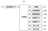
- the battery temperature control device 1 is controlled by the control device 70 shown in FIG.
- the control device 70 includes a well-known microcomputer including a CPU, a ROM, a RAM, and the like and peripheral circuits thereof.
- the control device 70 performs air conditioning control, temperature control of the secondary battery 10, temperature increase control of the secondary battery 10, and the like according to a control program stored in the ROM.
- the battery temperature sensor 13 and various switches are connected to the input side of the control device 70.
- the battery temperature sensor 13 is a sensor that detects the temperature of the secondary battery 10.
- the various switches are switches related to in-vehicle air conditioning.
- the device is connected.
- the control device 70 controls the operation of these controlled devices.
- the cooling water in the high-temperature cooling water circuit 30 is heated by the high-temperature side water-refrigerant heat exchanger 22. Since the cooling water of the high-temperature cooling water circuit 30 heated by the high-temperature side water-refrigerant heat exchanger 22 flows through the high-temperature side heater core 35, the air blown into the passenger compartment is heated by the high-temperature side heater core 35.
- the interior space of the vehicle interior is adjusted. It can be adjusted to an appropriate temperature.
- the high-temperature side electric heater 34 When the temperature of the cooling water in the high-temperature cooling water circuit 30 heated by the high-temperature side water-refrigerant heat exchanger 22 is not sufficiently increased, such as when the vehicle is started in a low outside air temperature environment, the high-temperature side electric heater 34 The temperature of the cooling water in the high-temperature cooling water circuit 30 is increased.
- the high-temperature side radiator 32 releases excess heat to the outside air.
- the inverter 45, and the motor generator 46 When it is necessary to warm up the secondary battery 10, the inverter 45, and the motor generator 46, such as when starting a vehicle in a low outside air temperature environment, the temperature of the cooling water in the low temperature cooling water circuit 40 is set by the low temperature side electric heater 44. Raise.
- the low-temperature side radiator 47 releases excess heat to the outside air.
- the control device 70 controls the charging / discharging of the secondary battery 10 by driving the inverter 45 to perform the ripple temperature increase control for causing the secondary battery 10 to self-heat by the ripple current flowing through the secondary battery 10.
- the ripple temperature rise control is performed based on the temperature of the secondary battery 10 detected by the battery temperature sensor 13 and the cell voltage of each battery cell 11 detected by the monitoring device included in the secondary battery 10.
- the control device 70 determines that the temperature of the secondary battery 10 is low, the electric energy transfer process from the secondary battery 10 to the smoothing capacitor 57 and the electric energy from the smoothing capacitor 57 to the secondary battery 10 are performed. And move processing. That is, the control device 70 performs ripple temperature increase control aiming at heat generation by the internal resistance due to charging / discharging of the secondary battery 10.
- the electric energy transfer process from the secondary battery 10 to the smoothing capacitor 57 is a boosting process in which the voltage of the secondary battery 10 is boosted and applied to the smoothing capacitor 57.
- the relay 56 is opened and the relay 58 is closed.
- the control apparatus 70 turns ON the 2nd switching element 54 of a lower arm about the V phase and W phase which are the legs which are not connected to the secondary battery 10 by the relay 58.
- FIG. As a result, a current flows through a loop path including the secondary battery 10, the relay 58, the motor generator 46, and the V-phase and W-phase second switching elements 54, and electric energy is stored in the motor generator 46.
- control device 70 turns off the V-phase and W-phase second switching elements 54, whereby the motor generator 46, the V-phase and W-phase upper arm diode 55, the smoothing capacitor 57, the secondary battery 10, and A current flows through a loop path including the relay 58, and the smoothing capacitor 57 is charged.
- the process of transferring electrical energy from the smoothing capacitor 57 to the secondary battery 10 is a step-down process in which the voltage of the smoothing capacitor 57 is stepped down and applied to the secondary battery 10.
- the control device 70 turns on the first switching element 53 of the upper arm for the V phase and the W phase, which are legs that are not connected to the secondary battery 10 by the relay 58.
- current flows through a loop path including the smoothing capacitor 57, the V-phase and W-phase first switching elements 53, the motor generator 46, the relay 58, and the secondary battery 10, and electric energy is stored in the motor generator 46.
- control device 70 includes the motor generator 46, the relay 58, the secondary battery 10, and the diode 55 of the lower arm of the V phase and the W phase by turning off the first switching element 53 of the V phase and the W phase. Current flows in the loop path.
- the inverter 45 and the motor generator 46 constitute a current generator that self-heats the secondary battery 10 by a ripple current.
- the ripple temperature raising control is a motor + inverter system in which the inverter 45 and the motor generator 46 are combined.
- the secondary battery 10 has the heat insulation structure covered with the heat insulation part 12.
- FIG. 4 shows, the thermal radiation from the secondary battery 10 to external environment can be suppressed. Thereby, the following effects are acquired.
- the temperature increase rate of the secondary battery 10 can be improved. Moreover, the temperature rising energy for flowing a ripple current can be reduced. For this reason, since the electric power of the secondary battery 10 is not consumed more than necessary, a decrease in the cruising distance of the vehicle can be suppressed.
- the heat of the secondary battery 10 is difficult to escape to the external environment by the heat insulating part 12, the temperature drop of the secondary battery 10 can be suppressed.
- the heat can be effectively used in the heat pump circuit 28 and the like.
- the heat insulating portion 12 disposed outside the secondary battery 10 may be disposed at a part of the outside of the secondary battery 10. Even if the heat insulating portion 12 covers the secondary battery 10, heat dissipation from the secondary battery 10 to the outside air can be suppressed. Therefore, the heat insulating portion 12 is effective even when the entire secondary battery 10 cannot be covered.
- the low-temperature cooling water circuit 40 and the heat pump circuit 28 of the present embodiment correspond to a heat medium circuit.
- the low-temperature cooling water circuit 40 corresponds to the cooling water circuit.
- the inverter 45 and the motor generator 46 correspond to a current generator.
- switching elements 53 and 54 and the diode 55 correspond to current switching means
- the coil of the motor generator 46 and the smoothing capacitor 57 correspond to power storage means.
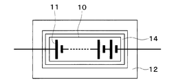
- the battery temperature adjustment device 1 has a heat storage unit 14 for storing heat released from the secondary battery 10.
- the heat storage unit 14 stores heat using the phase transition of the heat storage material.
- the heat storage unit 14 covers, for example, the entire secondary battery 10.
- the heat insulating part 12 is disposed outside the heat storage part 14.
- the heat insulation part 12 seals the secondary battery 10 and the heat storage part 14. It is desirable that there is a gap between the heat storage unit 14 and the heat insulating unit 12 for enhancing the heat insulating effect. Note that the wiring of the secondary battery 10 passes through the heat insulating portion 12 and the heat storage portion 14.
- the heat storage amount of the secondary battery 10 is increased by the heat storage unit 14, the effect of suppressing the temperature drop of the secondary battery 10 is increased. Further, the same effect as in the first embodiment can be obtained.
- the heat storage unit 14 may be disposed between the battery cells 11 instead of the outside of the secondary battery 10. That is, the battery cell 11 and the heat storage unit 14 are alternately stacked. Further, the heat storage unit 14 may be arranged in a part of the secondary battery 10 instead of the whole. For example, the heat insulation part 12 may be arrange
- the battery temperature adjustment device 1 does not have the heat insulation part 12 but has the heat storage part 14.
- the heat dissipation loss of the secondary battery 10 may be suppressed only by the heat storage unit 14.
- the effects and modifications of the heat storage unit 14 are the same as those in the second embodiment.
- waste heat is generated from the inverter 45 and the motor generator 46 during the ripple temperature increase control.
- the low-temperature cooling water circuit 40 and the heat pump circuit 28 receive waste heat generated by the inverter 45 and the motor generator 46 with cooling water or refrigerant as a heat medium.
- the waste heat of the inverter 45 and the motor generator 46 can be recovered by the low-temperature cooling water circuit 40 and the heat pump circuit 28. Further, the waste heat of the inverter 45 and the motor generator 46 can be used for heating the air in the high temperature side water-refrigerant heat exchanger 22. Thus, the heat generated to generate the ripple current can be used in the low-temperature cooling water circuit 40 and the heat pump circuit 28. Thereby, the cycle effect of the heat pump circuit 28 can be improved.
- the cooling water of the low-temperature cooling water circuit 40 cooled by the chiller 27 flows through the inverter 45 and the motor generator 46, the inverter 45 and the motor generator 46 can be cooled. Therefore, similarly to the first embodiment, it is possible to suppress heat dissipation loss due to ripple temperature rise. As described above, a certain proportion of waste heat that does not contribute to the temperature rise of the secondary battery 10 can be effectively used.
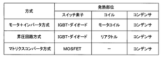
- the current generator When the current generator generates a ripple current by the motor + inverter system, the current generator configures a circuit including an IGBT, a diode, a motor coil, and a capacitor as a heat generating part.
- the operation of the motor + inverter system is the same as in the first embodiment.
- the current generator When the current generator generates a ripple current by a booster circuit system, the current generator is a system in which a circuit including an IGBT, a diode, a reactor, and a capacitor is formed as a heat generating part, and the high voltage side IGBT and the low voltage side IGBT are in series. Connected. A capacitor is connected in parallel to the series connection of the high voltage side IGBT and the low voltage side IGBT. A reactor is connected to the connection point of each IGBT. Each IGBT includes a diode. Secondary battery 10 is connected between the reactor and the low-voltage IGBT.
- the low-voltage side IGBT When boosting, the low-voltage side IGBT is turned on, a current is passed through the secondary battery 10 ⁇ reactor ⁇ low-voltage side IGBT, and energy is stored in the reactor. Thereafter, the low voltage side IGBT is turned off, and a current is passed through the battery, the reactor, the diode of the high voltage side IGBT, and the capacitor. Since the voltage on the secondary battery 10 side of the reactor is the voltage of the secondary battery 10, the boosted voltage is stored in the capacitor.
- the high-voltage side IGBT is turned on, and a current is passed through the capacitor ⁇ high-voltage side IGBT ⁇ reactor ⁇ secondary battery 10 to store energy in the reactor. Thereafter, the high voltage side IGBT is turned off, and a current is passed through the diode of the reactor ⁇ the secondary battery 10 ⁇ the low voltage side IGBT. Since the voltage on the diode side of the low voltage side IGBT of the reactor becomes 0V, the stepped down voltage is stored in the secondary battery 10.
- a ripple current is passed through the secondary battery 10 by repeating the above step-up and step-down.
- the temperature of the secondary battery 10 rises due to internal heat generation of the secondary battery 10.
- the direction of the secondary battery 10 ⁇ reactor is positive, the current flows in the positive direction when boosting, and the current flows in the reverse direction when decreasing.
- the current generator when the current generator generates a ripple current by the matrix converter method, the current generator constitutes a circuit including a MOSFET switch and a capacitor as a heat generating part.
- the secondary battery 10 constitutes a module including a MOSFET switch and a capacitor.
- the MOSFET switch opens and closes between the positive electrode of the battery cell 11 and one terminal of the in-module capacitor.
- the MOSFET switch opens and closes between the negative electrode of the battery cell 11 and the other terminal of the in-module capacitor.
- the temperature of the secondary battery 10 When the temperature of the secondary battery 10 is low, according to the switching operation of the MOSFET switch, some electric energy of the battery cell 11 is discharged to the capacitor in the secondary battery 10 to store the energy stored in the capacitor in the secondary battery 10. To charge some of the battery cells 11. That is, when the battery cell 11 is repeatedly charged and discharged, the temperature of the secondary battery 10 can be increased by heat generated by the internal resistance.
- boost circuit type IGBT and diode, and the matrix converter type MOSFET switch of the present embodiment correspond to the current switching means. Further, a booster circuit type reactor and capacitor, and a matrix converter type capacitor correspond to the power storage means.
- the heat of the cooling water is transferred to the refrigerant circulating through the heat pump circuit 28 through the chiller 27.
- the heat of the secondary battery 10 after the ripple temperature rise control can be used for air conditioning control.
- the battery temperature adjustment device 1 may be configured such that the refrigerant of the heat pump circuit 28 passes through the secondary battery 10. Thereby, the heat of the secondary battery 10 can be directly transferred to the heat pump circuit 28.
- FIG. 11 in the secondary battery 10, a first assembled battery 15a, a second assembled battery 15b, and a third assembled battery 15c, in which a plurality of battery cells 11 are connected in series, are connected in parallel. Switches 16a to 16c are connected in series to the assembled batteries 15a to 15c. The switches 16a to 16c are controlled by the control device 70.
- the supply of power from the first assembled battery 15a to the inverter 45 and the motor generator 46 is interrupted by the first switch 16a.
- the power supply from the second assembled battery 15b to the inverter 45 and the motor generator 46 is interrupted by the second switch 16b.
- the power supply from the third assembled battery 15c to the inverter 45 and the motor generator 46 is interrupted by the third switch 16c.
- the battery flow path 42 of the low-temperature cooling water circuit 40 includes a first battery flow path 42a, a second battery flow path 42b, and a third battery flow path 42c corresponding to each of the assembled batteries 15a to 15c. Yes.
- Each of the battery channels 42a to 42c is a cooling water channel through which the cooling water of the low-temperature cooling water circuit 40 flows.
- the first battery pack 15a is disposed in the first battery channel 42a.
- the temperature of the first assembled battery 15a is adjusted by the cooling water flowing through the first battery channel 42a.
- a first on-off valve 61a is disposed in the first battery channel 42a.
- the first on-off valve 61a is an electromagnetic valve that opens and closes the first battery channel 42a.
- the second battery pack 15b is disposed in the second battery channel 42b.
- the temperature of the second assembled battery 15b is adjusted by the cooling water flowing through the second battery channel 42b.
- a second on-off valve 61b is disposed in the second battery channel 42b.
- the second on-off valve 61b is an electromagnetic valve that opens and closes the second battery channel 42b.
- the third battery pack 15c is disposed in the third battery flow path 42c.
- the temperature of the third assembled battery 15c is adjusted by the cooling water flowing through the third battery channel 42c.
- a third on-off valve 61c is disposed in the third battery channel 42c.
- the third on-off valve 61c is an electromagnetic valve that opens and closes the third battery channel 42c.
- the cooling water in the low temperature side circulation channel 41 flows into the battery channels 42a to 42c, and the cooling water in the battery channels 42a to 42c is on the low temperature side.
- the cooling water circulates through the battery channels 42a to 42c.
- the circulation of the cooling water with respect to each of the battery flow paths 42a to 42c can be arbitrarily interrupted by the open / close control of each of the on / off valves 61a to 61c.
- the first assembled battery 15a is covered with the heat insulating portion 12. Thereby, a part of the secondary battery 10 can be subjected to ripple temperature rise control.
- cooling water or refrigerant is used as the heat medium, but various media such as oil may be used as the heat medium.
- a chlorofluorocarbon refrigerant is used as the refrigerant.
- the type of the refrigerant is not limited to this, and a natural refrigerant such as carbon dioxide, a hydrocarbon refrigerant, or the like may be used. good.
- the refrigeration cycle apparatus 20 of the above embodiment constitutes a subcritical refrigeration cycle in which the high-pressure side refrigerant pressure does not exceed the critical pressure of the refrigerant, but constitutes a supercritical refrigeration cycle in which the high-pressure side refrigerant pressure exceeds the critical pressure of the refrigerant. You may do it.
- the inlet side of the branch portion 23 a is connected to the outlet of the refrigerant passage of the high temperature side water-refrigerant heat exchanger 22, but it expands to the outlet of the refrigerant passage of the high temperature side water-refrigerant heat exchanger 22.
- a valve may be connected, and an outdoor unit may be connected to the expansion valve.
- An outdoor unit is connected to the inlet side of the branch part 23a.
- the battery temperature control device 1 is mounted on an electric vehicle.
- the battery temperature control device 1 is mounted on a hybrid vehicle that obtains driving force for vehicle travel from an internal combustion engine and a travel electric motor. Also good.
- the battery temperature control apparatus 1 is not restricted to vehicles, You may apply to the secondary batteries 10 other than vehicles.
- the ejector may be built in the indoor evaporator 25 of the above embodiment.
- the ejector sucks the fluid from the fluid suction port by the suction action of the high-speed jet fluid ejected from the nozzle.
- the ejector further increases the pressure of the mixed fluid by converting the velocity energy of the mixed fluid of the ejected fluid and the suction fluid sucked from the fluid suction port into pressure energy at the boosting unit.
- the booster is a so-called diffuser.
- the compressor 21 of the above embodiment may be a gas injection compressor.
- the gas injection compressor is a compressor that improves the compression efficiency by joining the intermediate pressure refrigerant generated in the cycle with the intermediate pressure refrigerant in the pressurization process and increasing the pressure of the refrigerant in multiple stages.
Landscapes
- Engineering & Computer Science (AREA)
- Manufacturing & Machinery (AREA)
- Chemical & Material Sciences (AREA)
- Chemical Kinetics & Catalysis (AREA)
- Electrochemistry (AREA)
- General Chemical & Material Sciences (AREA)
- Automation & Control Theory (AREA)
- Power Engineering (AREA)
- Secondary Cells (AREA)
- Inverter Devices (AREA)
- Electric Propulsion And Braking For Vehicles (AREA)
Applications Claiming Priority (2)
| Application Number | Priority Date | Filing Date | Title |
|---|---|---|---|
| JP2018-086329 | 2018-04-27 | ||
| JP2018086329A JP7008393B2 (ja) | 2018-04-27 | 2018-04-27 | 電池温調装置 |
Publications (1)
| Publication Number | Publication Date |
|---|---|
| WO2019208018A1 true WO2019208018A1 (ja) | 2019-10-31 |
Family
ID=68294433
Family Applications (1)
| Application Number | Title | Priority Date | Filing Date |
|---|---|---|---|
| PCT/JP2019/010918 Ceased WO2019208018A1 (ja) | 2018-04-27 | 2019-03-15 | 電池温調装置 |
Country Status (2)
| Country | Link |
|---|---|
| JP (1) | JP7008393B2 (enExample) |
| WO (1) | WO2019208018A1 (enExample) |
Cited By (1)
| Publication number | Priority date | Publication date | Assignee | Title |
|---|---|---|---|---|
| JP2024532530A (ja) * | 2022-03-23 | 2024-09-05 | 寧徳時代新能源科技股▲分▼有限公司 | 温度管理機器と試験システム |
Families Citing this family (2)
| Publication number | Priority date | Publication date | Assignee | Title |
|---|---|---|---|---|
| DE102022123893A1 (de) | 2022-09-19 | 2024-03-21 | Dr. Ing. H.C. F. Porsche Aktiengesellschaft | Pulswechselrichter und Verfahren zum Kühlen eines Pulswechselrichters |
| WO2024252491A1 (ja) * | 2023-06-05 | 2024-12-12 | 株式会社Tbk | バッテリ冷暖装置 |
Citations (4)
| Publication number | Priority date | Publication date | Assignee | Title |
|---|---|---|---|---|
| JP2010119171A (ja) * | 2008-11-11 | 2010-05-27 | Toyota Motor Corp | インバータの制御装置および制御方法 |
| JP2011178321A (ja) * | 2010-03-02 | 2011-09-15 | Toyota Industries Corp | 車両用空調システム |
| JP2013199251A (ja) * | 2012-03-26 | 2013-10-03 | Denso Corp | 車両用空調システム |
| WO2017038677A1 (ja) * | 2015-08-28 | 2017-03-09 | 株式会社デンソー | 空調システム |
Family Cites Families (2)
| Publication number | Priority date | Publication date | Assignee | Title |
|---|---|---|---|---|
| JPH0349168A (ja) * | 1989-07-17 | 1991-03-01 | Mitsubishi Electric Corp | 自動車用バツテリの温度制御装置 |
| JP2015015208A (ja) * | 2013-07-08 | 2015-01-22 | 株式会社東芝 | 電池モジュール、電池モジュールを有する電源装置、及び電池モジュールの温度管理方法 |
-
2018
- 2018-04-27 JP JP2018086329A patent/JP7008393B2/ja not_active Expired - Fee Related
-
2019
- 2019-03-15 WO PCT/JP2019/010918 patent/WO2019208018A1/ja not_active Ceased
Patent Citations (4)
| Publication number | Priority date | Publication date | Assignee | Title |
|---|---|---|---|---|
| JP2010119171A (ja) * | 2008-11-11 | 2010-05-27 | Toyota Motor Corp | インバータの制御装置および制御方法 |
| JP2011178321A (ja) * | 2010-03-02 | 2011-09-15 | Toyota Industries Corp | 車両用空調システム |
| JP2013199251A (ja) * | 2012-03-26 | 2013-10-03 | Denso Corp | 車両用空調システム |
| WO2017038677A1 (ja) * | 2015-08-28 | 2017-03-09 | 株式会社デンソー | 空調システム |
Cited By (2)
| Publication number | Priority date | Publication date | Assignee | Title |
|---|---|---|---|---|
| JP2024532530A (ja) * | 2022-03-23 | 2024-09-05 | 寧徳時代新能源科技股▲分▼有限公司 | 温度管理機器と試験システム |
| JP7665868B2 (ja) | 2022-03-23 | 2025-04-21 | 香港時代新能源科技有限公司 | 温度管理機器と試験システム |
Also Published As
| Publication number | Publication date |
|---|---|
| JP2019193501A (ja) | 2019-10-31 |
| JP7008393B2 (ja) | 2022-01-25 |
Similar Documents
| Publication | Publication Date | Title |
|---|---|---|
| JP6958493B2 (ja) | 電池温調装置 | |
| US11479077B2 (en) | Heat pump system for vehicle | |
| US9731576B2 (en) | EV multi-mode thermal management system | |
| US9511645B2 (en) | EV multi-mode thermal management system | |
| US9758010B2 (en) | EV multi mode thermal management system | |
| US9758011B2 (en) | EV multi-mode thermal management system | |
| US9731577B2 (en) | EV multi-mode thermal management system | |
| US9758012B2 (en) | EV multi-mode thermal management system | |
| US9731578B2 (en) | EV multi-mode thermal management system | |
| US9533544B2 (en) | EV multi-mode thermal management system | |
| EP3045331B1 (en) | Ev multi-mode thermal management system | |
| US9447994B2 (en) | Temperature control systems with thermoelectric devices | |
| US9748614B2 (en) | Battery temperature regulating device | |
| CN204987545U (zh) | 三环路温度控制系统 | |
| US9555686B2 (en) | Temperature control systems with thermoelectric devices | |
| CN103492204B (zh) | 车辆温度控制设备和车载热系统 | |
| US20130192272A1 (en) | Temperature control systems with thermoelectric devices | |
| CN109941117B (zh) | 电动车辆 | |
| WO2013151903A1 (en) | Temperature control systems with thermoelectric devices | |
| CN104159763A (zh) | 调温装置 | |
| JP2015191703A (ja) | 電池温度調節装置 | |
| JP7354599B2 (ja) | 車両用熱管理システム | |
| JP2019186058A (ja) | 電池温調装置 | |
| WO2019208018A1 (ja) | 電池温調装置 | |
| JP7497857B2 (ja) | 車両用空気調温システム |
Legal Events
| Date | Code | Title | Description |
|---|---|---|---|
| 121 | Ep: the epo has been informed by wipo that ep was designated in this application |
Ref document number: 19791830 Country of ref document: EP Kind code of ref document: A1 |
|
| NENP | Non-entry into the national phase |
Ref country code: DE |
|
| 122 | Ep: pct application non-entry in european phase |
Ref document number: 19791830 Country of ref document: EP Kind code of ref document: A1 |