WO2019208018A1 - Battery temperature adjustment device - Google Patents
Battery temperature adjustment device Download PDFInfo
- Publication number
- WO2019208018A1 WO2019208018A1 PCT/JP2019/010918 JP2019010918W WO2019208018A1 WO 2019208018 A1 WO2019208018 A1 WO 2019208018A1 JP 2019010918 W JP2019010918 W JP 2019010918W WO 2019208018 A1 WO2019208018 A1 WO 2019208018A1
- Authority
- WO
- WIPO (PCT)
- Prior art keywords
- heat
- secondary battery
- battery
- control device
- cooling water
- Prior art date
Links
Images


Classifications
-
- H—ELECTRICITY
- H01—ELECTRIC ELEMENTS
- H01M—PROCESSES OR MEANS, e.g. BATTERIES, FOR THE DIRECT CONVERSION OF CHEMICAL ENERGY INTO ELECTRICAL ENERGY
- H01M10/00—Secondary cells; Manufacture thereof
- H01M10/60—Heating or cooling; Temperature control
- H01M10/61—Types of temperature control
- H01M10/613—Cooling or keeping cold
-
- H—ELECTRICITY
- H01—ELECTRIC ELEMENTS
- H01M—PROCESSES OR MEANS, e.g. BATTERIES, FOR THE DIRECT CONVERSION OF CHEMICAL ENERGY INTO ELECTRICAL ENERGY
- H01M10/00—Secondary cells; Manufacture thereof
- H01M10/60—Heating or cooling; Temperature control
- H01M10/61—Types of temperature control
- H01M10/615—Heating or keeping warm
-
- H—ELECTRICITY
- H01—ELECTRIC ELEMENTS
- H01M—PROCESSES OR MEANS, e.g. BATTERIES, FOR THE DIRECT CONVERSION OF CHEMICAL ENERGY INTO ELECTRICAL ENERGY
- H01M10/00—Secondary cells; Manufacture thereof
- H01M10/60—Heating or cooling; Temperature control
- H01M10/62—Heating or cooling; Temperature control specially adapted for specific applications
- H01M10/625—Vehicles
-
- H—ELECTRICITY
- H01—ELECTRIC ELEMENTS
- H01M—PROCESSES OR MEANS, e.g. BATTERIES, FOR THE DIRECT CONVERSION OF CHEMICAL ENERGY INTO ELECTRICAL ENERGY
- H01M10/00—Secondary cells; Manufacture thereof
- H01M10/60—Heating or cooling; Temperature control
- H01M10/63—Control systems
- H01M10/637—Control systems characterised by the use of reversible temperature-sensitive devices, e.g. NTC, PTC or bimetal devices; characterised by control of the internal current flowing through the cells, e.g. by switching
-
- H—ELECTRICITY
- H01—ELECTRIC ELEMENTS
- H01M—PROCESSES OR MEANS, e.g. BATTERIES, FOR THE DIRECT CONVERSION OF CHEMICAL ENERGY INTO ELECTRICAL ENERGY
- H01M10/00—Secondary cells; Manufacture thereof
- H01M10/60—Heating or cooling; Temperature control
- H01M10/65—Means for temperature control structurally associated with the cells
- H01M10/655—Solid structures for heat exchange or heat conduction
- H01M10/6552—Closed pipes transferring heat by thermal conductivity or phase transition, e.g. heat pipes
-
- H—ELECTRICITY
- H01—ELECTRIC ELEMENTS
- H01M—PROCESSES OR MEANS, e.g. BATTERIES, FOR THE DIRECT CONVERSION OF CHEMICAL ENERGY INTO ELECTRICAL ENERGY
- H01M10/00—Secondary cells; Manufacture thereof
- H01M10/60—Heating or cooling; Temperature control
- H01M10/65—Means for temperature control structurally associated with the cells
- H01M10/655—Solid structures for heat exchange or heat conduction
- H01M10/6556—Solid parts with flow channel passages or pipes for heat exchange
-
- H—ELECTRICITY
- H01—ELECTRIC ELEMENTS
- H01M—PROCESSES OR MEANS, e.g. BATTERIES, FOR THE DIRECT CONVERSION OF CHEMICAL ENERGY INTO ELECTRICAL ENERGY
- H01M10/00—Secondary cells; Manufacture thereof
- H01M10/60—Heating or cooling; Temperature control
- H01M10/65—Means for temperature control structurally associated with the cells
- H01M10/656—Means for temperature control structurally associated with the cells characterised by the type of heat-exchange fluid
- H01M10/6567—Liquids
- H01M10/6568—Liquids characterised by flow circuits, e.g. loops, located externally to the cells or cell casings
-
- H—ELECTRICITY
- H01—ELECTRIC ELEMENTS
- H01M—PROCESSES OR MEANS, e.g. BATTERIES, FOR THE DIRECT CONVERSION OF CHEMICAL ENERGY INTO ELECTRICAL ENERGY
- H01M10/00—Secondary cells; Manufacture thereof
- H01M10/60—Heating or cooling; Temperature control
- H01M10/65—Means for temperature control structurally associated with the cells
- H01M10/658—Means for temperature control structurally associated with the cells by thermal insulation or shielding
-
- H—ELECTRICITY
- H01—ELECTRIC ELEMENTS
- H01M—PROCESSES OR MEANS, e.g. BATTERIES, FOR THE DIRECT CONVERSION OF CHEMICAL ENERGY INTO ELECTRICAL ENERGY
- H01M10/00—Secondary cells; Manufacture thereof
- H01M10/60—Heating or cooling; Temperature control
- H01M10/66—Heat-exchange relationships between the cells and other systems, e.g. central heating systems or fuel cells
- H01M10/667—Heat-exchange relationships between the cells and other systems, e.g. central heating systems or fuel cells the system being an electronic component, e.g. a CPU, an inverter or a capacitor
-
- H—ELECTRICITY
- H02—GENERATION; CONVERSION OR DISTRIBUTION OF ELECTRIC POWER
- H02M—APPARATUS FOR CONVERSION BETWEEN AC AND AC, BETWEEN AC AND DC, OR BETWEEN DC AND DC, AND FOR USE WITH MAINS OR SIMILAR POWER SUPPLY SYSTEMS; CONVERSION OF DC OR AC INPUT POWER INTO SURGE OUTPUT POWER; CONTROL OR REGULATION THEREOF
- H02M7/00—Conversion of ac power input into dc power output; Conversion of dc power input into ac power output
- H02M7/42—Conversion of dc power input into ac power output without possibility of reversal
- H02M7/44—Conversion of dc power input into ac power output without possibility of reversal by static converters
- H02M7/48—Conversion of dc power input into ac power output without possibility of reversal by static converters using discharge tubes with control electrode or semiconductor devices with control electrode
-
- Y—GENERAL TAGGING OF NEW TECHNOLOGICAL DEVELOPMENTS; GENERAL TAGGING OF CROSS-SECTIONAL TECHNOLOGIES SPANNING OVER SEVERAL SECTIONS OF THE IPC; TECHNICAL SUBJECTS COVERED BY FORMER USPC CROSS-REFERENCE ART COLLECTIONS [XRACs] AND DIGESTS
- Y02—TECHNOLOGIES OR APPLICATIONS FOR MITIGATION OR ADAPTATION AGAINST CLIMATE CHANGE
- Y02E—REDUCTION OF GREENHOUSE GAS [GHG] EMISSIONS, RELATED TO ENERGY GENERATION, TRANSMISSION OR DISTRIBUTION
- Y02E60/00—Enabling technologies; Technologies with a potential or indirect contribution to GHG emissions mitigation
- Y02E60/10—Energy storage using batteries
Definitions
- the present disclosure relates to a battery temperature control device.
- Patent Document 1 a technique for generating a large current in a secondary battery whose output has been significantly reduced by repeatedly charging and discharging the secondary battery using an external circuit and raising the temperature by self-heating due to the internal resistance of the secondary battery is, for example, This is proposed in Patent Document 1.
- This disclosure aims to provide a battery temperature control device that can suppress heat dissipation loss due to a ripple temperature increase of a secondary battery.
- the battery temperature control apparatus is an apparatus that self-heats a secondary battery by a ripple current flowing in the secondary battery by controlling charge / discharge of the chargeable / dischargeable secondary battery. .
- the battery temperature control device includes a heat insulating portion that is disposed outside the secondary battery and insulates heat released from the secondary battery.
- the battery temperature control device includes a heat storage unit that stores heat released from the secondary battery.
- the heat of the secondary battery is stored in the heat storage part and is difficult to escape to the external environment, and the heat energy once stored can be used in the secondary battery and other devices. Therefore, it is possible to suppress heat dissipation loss due to ripple temperature rise of the secondary battery.
- the battery temperature control device includes a current generator and a heat medium circuit.
- the current generator controls the charge / discharge of the chargeable / dischargeable secondary battery to self-heat the secondary battery by the ripple current flowing through the secondary battery.
- the heat medium circuit circulates the heat medium and receives heat generated by the current generator with the heat medium.
- the heat generated by the current generator is transferred to the heat medium circuit, the heat generated to generate the ripple current can be used in the heat medium circuit. Therefore, it is possible to suppress heat dissipation loss due to ripple temperature rise of the secondary battery.
- FIG. 1 is a diagram showing a battery temperature control device according to the first embodiment.
- FIG. 2 is a circuit diagram of the inverter.
- FIG. 3 is a diagram for explaining a control device included in the battery temperature control device,
- FIG. 4 is a diagram for explaining the effect of the heat insulating portion.
- FIG. 5 is a diagram illustrating a secondary battery according to the second embodiment.
- FIG. 6 is a diagram illustrating a secondary battery according to the third embodiment.
- FIG. 7 is a view showing a part of the battery temperature control device according to the fourth embodiment, FIG.
- FIG. 8 is a diagram illustrating an inverter driving method according to the fourth embodiment.
- FIG. 9 is a view showing a part of the battery temperature control device according to the fifth embodiment
- FIG. 10 is a diagram showing a part of the battery temperature control device according to the sixth embodiment
- FIG. 11 is a diagram showing a battery temperature control device according to the seventh embodiment.
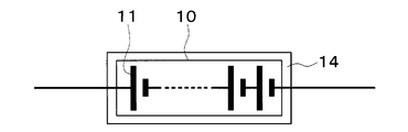
- a battery temperature control device 1 shown in FIG. 1 is a device that adjusts a secondary battery 10 mounted on a vehicle to an appropriate temperature.
- the battery temperature control device 1 is a device that self-heats the secondary battery 10 by a ripple current flowing through the secondary battery 10 by controlling charging and discharging of the secondary battery 10.
- the battery temperature control device 1 also functions as an air conditioner that adjusts the interior space of the vehicle to an appropriate temperature.
- the battery temperature control device 1 is mounted on an electric vehicle that obtains a driving force for driving a vehicle from an electric motor for driving.
- the electric vehicle can charge the secondary battery 10 mounted on the vehicle with electric power supplied from an external power source when the vehicle is stopped.
- the external power source is, for example, a commercial power source.
- the electric power stored in the secondary battery 10 is supplied not only to the electric motor for traveling but also to various in-vehicle devices including the electric components constituting the battery temperature control device 1.
- the secondary battery 10 has a plurality of chargeable / dischargeable battery cells 11.
- a lithium ion battery can be used, for example.
- this type of battery is at a low temperature, the chemical reaction is difficult to proceed, and sufficient performance with respect to charging and discharging cannot be exhibited.
- this type of battery is likely to deteriorate at a high temperature. Therefore, the temperature of each battery cell 11 is adjusted within an appropriate temperature range that can exhibit sufficient performance.
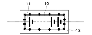
- the battery temperature control apparatus 1 has a heat insulating part 12 for insulating heat released from the secondary battery 10.
- a material such as a vacuum heat insulating material, glass wool, or polyurethane foam is used as the heat insulating portion 12.
- the heat insulating part 12 is disposed outside the secondary battery 10.
- the heat insulating part 12 covers a part or the whole of the secondary battery 10.
- the wiring penetrates the heat insulating portion 12.
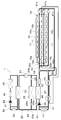
- the battery temperature control device 1 has a refrigeration cycle device 20.
- each component apparatus which comprises the refrigerating-cycle apparatus 20 is demonstrated.
- Compressor 21 draws in refrigerant in refrigeration cycle apparatus 20, compresses it, and discharges it.
- the compressor 21 is arrange
- the compressor 21 is an electric compressor that rotationally drives a fixed capacity type compression mechanism with a fixed discharge capacity by an electric motor.
- the rotation speed (that is, the refrigerant discharge capacity) of the compressor 21 is controlled by a control signal output from the control device 70 described later.
- the inlet side of the refrigerant passage of the high temperature side water-refrigerant heat exchanger 22 is connected to the discharge port of the compressor 21.
- the high temperature side water-refrigerant heat exchanger 22 heat-exchanges the high pressure refrigerant discharged from the compressor 21 and the high temperature side heat medium circulating in the high temperature cooling water circuit 30 to heat the high temperature side heat medium. It is.
- As the high temperature side heat medium a solution containing ethylene glycol, an antifreeze solution, or the like can be used.
- the high-temperature cooling water circuit 30 is a high-temperature side water circuit that circulates the high-temperature side heat medium.
- the high temperature coolant circuit 30 has a high temperature side circulation channel 31.
- the high temperature side circulation channel 31 is a cooling water channel through which high temperature side cooling water circulates as a high temperature side heat medium.
- a water passage of the high temperature side water-refrigerant heat exchanger 22, a high temperature side radiator 32, a high temperature side pump 33, a high temperature side electric heater 34, a high temperature side heater core 35, and the like are arranged.
- the high temperature side radiator 32 is arranged on the front side in the vehicle bonnet.
- the high temperature side radiator 32 may be formed integrally with the high temperature side water-refrigerant heat exchanger 22 or the like.
- the high temperature side radiator 32 exchanges heat between the high temperature side heat medium heated by the high temperature side water-refrigerant heat exchanger 22 and the outside air blown from an outside air fan (not shown), and the heat of the high temperature side heat medium is transferred to the outside air. It is a heat exchanger that dissipates heat.
- the high temperature side pump 33 is a high temperature side water pump that pumps the high temperature side heat medium to the high temperature side electric heater 34 in the high temperature cooling water circuit 30.
- the high temperature side pump 33 is an electric pump in which the rotation speed (that is, the water pressure feeding capacity) is controlled by the control voltage output from the control device 70.
- the high temperature side electric heater 34 is an auxiliary heater that generates heat when electric power is supplied and heats the high temperature side heat medium of the high temperature cooling water circuit 30 that is pumped from the high temperature side pump 33.
- the high temperature side heater core 35 is disposed in an air conditioning casing which will be described later.
- the high temperature side heater core 35 is a heat exchanger that heats the blown air by exchanging heat between the high temperature side heat medium heated by the high temperature side electric heater 34 and the blown air.
- the high temperature side pump 33, the high temperature side electric heater 34, the high temperature side heater core 35, the high temperature side water-refrigerant heat exchanger 22 and the like disposed in the high temperature cooling water circuit 30 are discharged from the compressor 21.
- a heating unit is configured to heat the blown air using the refrigerant as a heat source.
- the high temperature cooling water circuit 30 has a path connected in parallel to the high temperature side radiator 32.
- the path connected in parallel to the high temperature side radiator 32 is a detour path that bypasses the high temperature side radiator 32.
- a thermostat valve (not shown) is provided at a branch point between the bypass path and the path of the high-temperature side radiator 32. Accordingly, the high temperature side heat medium flows through the path of the high temperature side radiator 32 or the detour path according to the temperature of the high temperature side heat medium of the high temperature cooling water circuit 30.
- the outlet side of the branch portion 23 a is connected to the outlet of the refrigerant passage of the high temperature side water-refrigerant heat exchanger 22.
- the branch portion 23a branches the refrigerant flow that has flowed out of the high-temperature side water-refrigerant heat exchanger 22.
- the branch part 23a has a three-way joint structure with three inflow / outflow ports communicating with each other. In the branch portion 23a, one of the three inlets and outlets is a refrigerant inflow port, and the remaining two are refrigerant outlets.
- a receiver may be connected to the outlet of the refrigerant passage of the high temperature side water-refrigerant heat exchanger 22.
- the receiver separates the gas-liquid of the high-pressure refrigerant that has flowed out of the high-temperature water-refrigerant heat exchanger 22 and causes the separated liquid-phase refrigerant to flow downstream, and stores the excess refrigerant in the cycle as the liquid-phase refrigerant. It is a separation part.
- the receiver is a bottomed cylindrical container.
- the receiver may be formed integrally with the high temperature side water-refrigerant heat exchanger 22 or the like.
- the inlet side of the cooling expansion valve 24a is connected to one outlet of the branch portion 23a.
- An inlet side of the endothermic expansion valve 24b is connected to the other outlet of the branch portion 23a.
- the cooling expansion valve 24a is a pressure reducing unit that depressurizes the refrigerant flowing out of the high-temperature side water-refrigerant heat exchanger 22 at least in the cooling mode and the dehumidifying heating mode, and controls the flow rate of the refrigerant flowing into the indoor evaporator 25. This is a cooling flow rate adjusting unit to be adjusted.
- the cooling expansion valve 24a is an electric variable throttle mechanism that includes a valve body that can change the throttle opening degree and an electric actuator that changes the opening degree of the valve body.
- the electric actuator is a stepping motor.
- the operation of the cooling expansion valve 24 a is controlled by a control signal output from the control device 70.
- the control signal is, for example, a control pulse.
- the cooling expansion valve 24a has a fully closed function of closing the refrigerant passage by closing the valve opening degree.
- the refrigerant inlet side of the indoor evaporator 25 is connected to the outlet of the cooling expansion valve 24a.
- the indoor evaporator 25 is disposed in the air conditioning casing. More specifically, the indoor evaporator 25 is disposed on the upstream side of the blowing air flow with respect to the high temperature side heater core 35.
- the indoor evaporator 25 is a cooling unit that heat-exchanges the low-pressure refrigerant decompressed by the cooling expansion valve 24a and the blown air to evaporate the low-pressure refrigerant and cool the blown air at least in the cooling mode and the dehumidifying heating mode. It is an evaporation part.
- the inlet side of the evaporation pressure adjusting valve 26 is connected to the refrigerant outlet of the indoor evaporator 25.
- the evaporation pressure adjusting valve 26 is an evaporation pressure adjusting unit that maintains the refrigerant evaporation pressure in the indoor evaporator 25 at or above a predetermined reference pressure.
- the evaporation pressure adjusting valve 26 is configured by a mechanical variable throttle mechanism that increases the valve opening as the refrigerant pressure on the outlet side of the indoor evaporator 25 increases.
- an evaporating pressure adjusting valve 26 that maintains the refrigerant evaporating temperature in the indoor evaporator 25 at or above a reference temperature capable of suppressing frost formation in the indoor evaporator 25 is employed.
- the reference temperature is 1 ° C., for example.
- the outlet of the evaporation pressure adjusting valve 26 is connected to one inlet side of the merging portion 23b.
- the junction 23 b joins the refrigerant flow that has flowed out of the evaporation pressure adjusting valve 26 and the refrigerant flow that has flowed out of the chiller 27.
- the basic configuration of the merging portion 23b is the same as that of the branching portion 23a. That is, the merge part has a three-way joint structure. Two of the three inlets and outlets are refrigerant inlets, and the remaining one is a refrigerant outlet.
- the endothermic expansion valve 24b is a pressure reducing unit that depressurizes the refrigerant that has flowed out of the high-temperature side water-refrigerant heat exchanger 22 at least in the heating mode, and also adjusts the flow rate of the refrigerant that flows into the chiller 27. It is.
- the basic configuration of the endothermic expansion valve 24b is the same as that of the cooling expansion valve 24a.
- the inlet side of the refrigerant passage of the chiller 27 is connected to the outlet of the endothermic expansion valve 24b.
- the chiller 27 exchanges heat between the low-pressure refrigerant decompressed by the endothermic expansion valve 24b and the low-temperature side heat medium circulating in the low-temperature cooling water circuit 40 at least in the heating mode, evaporates the low-pressure refrigerant, and absorbs heat to the refrigerant.
- a solution containing ethylene glycol, an antifreeze solution, or the like can be used as the low-temperature heat medium.
- the refrigerant circuit formed by the refrigeration cycle apparatus 20 is a heat pump circuit 28 that draws heat from the low-temperature cooling water circuit 40 on the low temperature side to the refrigerant circuit on the high temperature side by circulating the refrigerant. That is, the heat of the cooling water circulating through the low-temperature cooling water circuit 40 is transferred to the refrigerant circulating through the heat pump circuit 28.
- the chiller 27 absorbs heat from the cooling water to the refrigerant. Thus, the heat of the cooling water is transferred from the low-temperature cooling water circuit 40 to the heat pump circuit 28 via the chiller 27.
- the other inlet side of the merging portion 23b is connected to the outlet of the refrigerant passage of the chiller 27.
- the suction port side of the compressor 21 is connected to the outlet of the junction 23b.
- the low-temperature cooling water circuit 40 is a low-temperature side water circuit for circulating the low-temperature side heat medium.
- the low temperature cooling water circuit 40 includes a low temperature side circulation channel 41 and a battery channel 42.
- the low temperature side circulation channel 41 is a channel through which low temperature side cooling water circulates as a low temperature side heat medium.
- a low temperature side pump 43, a chiller 27, a low temperature side electric heater 44, an inverter 45, a motor generator 46, and a low temperature side radiator 47 are arranged in the low temperature side circulation passage 41.
- the low temperature side pump 43 is a low temperature side water pump that pumps the low temperature side heat medium to the inlet side of the water passage of the chiller 27 in the low temperature cooling water circuit 40.
- the basic configuration of the low temperature side pump 43 is the same as that of the high temperature side pump 33.
- the low temperature side electric heater 44 is an auxiliary heater that generates heat when electric power is supplied and heats the cooling water of the low temperature cooling water circuit 40.
- the inverter 45 is a power conversion device that converts DC power supplied from the secondary battery 10 into AC power and outputs the AC power to the motor generator 46.
- the motor generator 46 uses the electric power output from the inverter 45 to generate a driving force for traveling and also generates regenerative electric power during deceleration or downhill.
- the inverter 45 and the motor generator 46 are adjusted by the cooling water of the low-temperature cooling water circuit 40 within an appropriate temperature range in which sufficient performance can be exhibited.
- the motor generator 46 is a three-phase rotating machine in which, for example, three coils of a U phase, a V phase, and a W phase are connected at a neutral point. Terminals that are not on the neutral point side of the motor generator 46 are connected to the secondary battery 10 via the inverter 45.
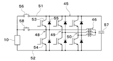
- the inverter 45 generates a three-phase AC voltage and current of U phase, V phase, and W phase to drive the high voltage motor generator 46. Therefore, inverter 45 has U-phase arm 48, V-phase arm 49, and W-phase arm 50. These arms 48 to 50 are connected in parallel between the positive electrode side wiring 51 and the negative electrode side wiring 52.
- Each arm 48 to 50 has two switching elements 53 and 54 connected in series.
- the first switching element 53 is connected to the positive electrode side wiring 51.
- the second switching element 54 is connected between the first switching element 53 and the negative electrode side wiring 52.
- a diode 55 is connected between the collector and emitter of each of the switching elements 53 and 54 to allow current to flow from the emitter side to the collector side.
- the connection points of the switching elements 53 and 54 are connected to the terminals of the motor generator 46.
- Each of the switching elements 53 and 54 is, for example, an IGBT (Insulated Gate Gate Bipolar Transistor).
- Each diode 55 is an FWD (Free Wheeling Diode).
- the positive electrode of the secondary battery 10 is connected to the positive electrode side wiring 51 of the inverter 45 through the relay 56. Further, a smoothing capacitor 57 is connected between the positive electrode side wiring 51 and the negative electrode side wiring 52 of the inverter 45.
- the positive electrode of the secondary battery 10 is connected via a relay 58 to a connection point of the switching elements 53 and 54 corresponding to the U phase.
- the relays 56 and 58 for example, movable contact type electromagnetic relays are used.
- the switching elements 53 and 54 and the relays 56 and 58 are electronically operated by an operation signal from a control device 70 described later.
- the low temperature side radiator 47 is formed integrally with the chiller 27 and the like, and is disposed on the front side in the vehicle bonnet.
- the low temperature side radiator 47 is a heat exchanger that exchanges heat between the low temperature side heat medium cooled by the chiller 27 and the outside air blown from the outside air fan, and causes the low temperature side heat medium to absorb heat from the outside air.
- the low-temperature cooling water circuit 40 has a path connected in parallel to the low-temperature side radiator 47.
- the path connected in parallel to the low temperature side radiator 47 is a detour path that bypasses the low temperature side radiator 47.
- a thermostat valve (not shown) is provided at a branch point between the bypass path and the path of the low-temperature side radiator 47. Accordingly, the low temperature side heat medium flows through the path of the low temperature side radiator 47 or the detour path according to the temperature of the low temperature side heat medium of the low temperature cooling water circuit 40.
- a first three-way valve 59 and a second three-way valve 60 are arranged at a connection portion between the low temperature side circulation channel 41 and the battery channel 42.
- the first three-way valve 59 is an electromagnetic valve that switches between a state in which the cooling water of the low-temperature side circulation passage 41 flows into the battery passage 42 and a state in which the cooling water does not flow into the battery passage 42.
- the second three-way valve 60 is an electromagnetic valve that switches between a state in which the cooling water in the battery passage 42 flows out to the low temperature side circulation passage 41 and a state in which it does not flow out. Therefore, it can be said that the low-temperature cooling water circuit 40 is a heat medium circuit that receives the heat of the secondary battery 10 with the cooling water that is the heat medium.
- the refrigerant circuit formed by the refrigeration cycle apparatus 20 can be said to be a heat medium circuit that receives the heat of the cooling water with the refrigerant that is the heat medium via the chiller 27.
- the indoor evaporator 25 and the high temperature side heater core 35 are accommodated in an air conditioning casing (not shown).
- the high temperature side heater core 35 is disposed on the downstream side of the air flow of the indoor evaporator 25 in the air passage in the air conditioning casing.
- Inside air and outside air are switched and introduced into the air conditioning casing.
- the inside air and outside air introduced into the air conditioning casing are blown to the indoor evaporator 25 and the high temperature side heater core 35 by a blower (not shown).
- An air mix door (not shown) is disposed between the indoor evaporator 25 and the high temperature side heater core 35 in the air passage in the air conditioning casing.
- the air mix door adjusts the air volume ratio between the cool air that has passed through the indoor evaporator 25 and that flows into the high-temperature heater core 35 and the cool air that bypasses the high-temperature heater core 35.
- the conditioned air whose temperature has been adjusted by the air mix door is blown into the passenger compartment from an unillustrated air outlet formed in the air conditioning casing.
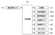
- the battery temperature control device 1 is controlled by the control device 70 shown in FIG.
- the control device 70 includes a well-known microcomputer including a CPU, a ROM, a RAM, and the like and peripheral circuits thereof.
- the control device 70 performs air conditioning control, temperature control of the secondary battery 10, temperature increase control of the secondary battery 10, and the like according to a control program stored in the ROM.
- the battery temperature sensor 13 and various switches are connected to the input side of the control device 70.
- the battery temperature sensor 13 is a sensor that detects the temperature of the secondary battery 10.
- the various switches are switches related to in-vehicle air conditioning.
- the device is connected.
- the control device 70 controls the operation of these controlled devices.
- the cooling water in the high-temperature cooling water circuit 30 is heated by the high-temperature side water-refrigerant heat exchanger 22. Since the cooling water of the high-temperature cooling water circuit 30 heated by the high-temperature side water-refrigerant heat exchanger 22 flows through the high-temperature side heater core 35, the air blown into the passenger compartment is heated by the high-temperature side heater core 35.
- the interior space of the vehicle interior is adjusted. It can be adjusted to an appropriate temperature.
- the high-temperature side electric heater 34 When the temperature of the cooling water in the high-temperature cooling water circuit 30 heated by the high-temperature side water-refrigerant heat exchanger 22 is not sufficiently increased, such as when the vehicle is started in a low outside air temperature environment, the high-temperature side electric heater 34 The temperature of the cooling water in the high-temperature cooling water circuit 30 is increased.
- the high-temperature side radiator 32 releases excess heat to the outside air.
- the inverter 45, and the motor generator 46 When it is necessary to warm up the secondary battery 10, the inverter 45, and the motor generator 46, such as when starting a vehicle in a low outside air temperature environment, the temperature of the cooling water in the low temperature cooling water circuit 40 is set by the low temperature side electric heater 44. Raise.
- the low-temperature side radiator 47 releases excess heat to the outside air.
- the control device 70 controls the charging / discharging of the secondary battery 10 by driving the inverter 45 to perform the ripple temperature increase control for causing the secondary battery 10 to self-heat by the ripple current flowing through the secondary battery 10.
- the ripple temperature rise control is performed based on the temperature of the secondary battery 10 detected by the battery temperature sensor 13 and the cell voltage of each battery cell 11 detected by the monitoring device included in the secondary battery 10.
- the control device 70 determines that the temperature of the secondary battery 10 is low, the electric energy transfer process from the secondary battery 10 to the smoothing capacitor 57 and the electric energy from the smoothing capacitor 57 to the secondary battery 10 are performed. And move processing. That is, the control device 70 performs ripple temperature increase control aiming at heat generation by the internal resistance due to charging / discharging of the secondary battery 10.
- the electric energy transfer process from the secondary battery 10 to the smoothing capacitor 57 is a boosting process in which the voltage of the secondary battery 10 is boosted and applied to the smoothing capacitor 57.
- the relay 56 is opened and the relay 58 is closed.
- the control apparatus 70 turns ON the 2nd switching element 54 of a lower arm about the V phase and W phase which are the legs which are not connected to the secondary battery 10 by the relay 58.
- FIG. As a result, a current flows through a loop path including the secondary battery 10, the relay 58, the motor generator 46, and the V-phase and W-phase second switching elements 54, and electric energy is stored in the motor generator 46.
- control device 70 turns off the V-phase and W-phase second switching elements 54, whereby the motor generator 46, the V-phase and W-phase upper arm diode 55, the smoothing capacitor 57, the secondary battery 10, and A current flows through a loop path including the relay 58, and the smoothing capacitor 57 is charged.
- the process of transferring electrical energy from the smoothing capacitor 57 to the secondary battery 10 is a step-down process in which the voltage of the smoothing capacitor 57 is stepped down and applied to the secondary battery 10.
- the control device 70 turns on the first switching element 53 of the upper arm for the V phase and the W phase, which are legs that are not connected to the secondary battery 10 by the relay 58.
- current flows through a loop path including the smoothing capacitor 57, the V-phase and W-phase first switching elements 53, the motor generator 46, the relay 58, and the secondary battery 10, and electric energy is stored in the motor generator 46.
- control device 70 includes the motor generator 46, the relay 58, the secondary battery 10, and the diode 55 of the lower arm of the V phase and the W phase by turning off the first switching element 53 of the V phase and the W phase. Current flows in the loop path.
- the inverter 45 and the motor generator 46 constitute a current generator that self-heats the secondary battery 10 by a ripple current.
- the ripple temperature raising control is a motor + inverter system in which the inverter 45 and the motor generator 46 are combined.
- the secondary battery 10 has the heat insulation structure covered with the heat insulation part 12.
- FIG. 4 shows, the thermal radiation from the secondary battery 10 to external environment can be suppressed. Thereby, the following effects are acquired.
- the temperature increase rate of the secondary battery 10 can be improved. Moreover, the temperature rising energy for flowing a ripple current can be reduced. For this reason, since the electric power of the secondary battery 10 is not consumed more than necessary, a decrease in the cruising distance of the vehicle can be suppressed.
- the heat of the secondary battery 10 is difficult to escape to the external environment by the heat insulating part 12, the temperature drop of the secondary battery 10 can be suppressed.
- the heat can be effectively used in the heat pump circuit 28 and the like.
- the heat insulating portion 12 disposed outside the secondary battery 10 may be disposed at a part of the outside of the secondary battery 10. Even if the heat insulating portion 12 covers the secondary battery 10, heat dissipation from the secondary battery 10 to the outside air can be suppressed. Therefore, the heat insulating portion 12 is effective even when the entire secondary battery 10 cannot be covered.
- the low-temperature cooling water circuit 40 and the heat pump circuit 28 of the present embodiment correspond to a heat medium circuit.
- the low-temperature cooling water circuit 40 corresponds to the cooling water circuit.
- the inverter 45 and the motor generator 46 correspond to a current generator.
- switching elements 53 and 54 and the diode 55 correspond to current switching means
- the coil of the motor generator 46 and the smoothing capacitor 57 correspond to power storage means.
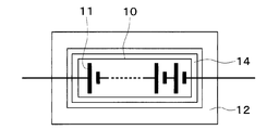
- the battery temperature adjustment device 1 has a heat storage unit 14 for storing heat released from the secondary battery 10.
- the heat storage unit 14 stores heat using the phase transition of the heat storage material.
- the heat storage unit 14 covers, for example, the entire secondary battery 10.
- the heat insulating part 12 is disposed outside the heat storage part 14.
- the heat insulation part 12 seals the secondary battery 10 and the heat storage part 14. It is desirable that there is a gap between the heat storage unit 14 and the heat insulating unit 12 for enhancing the heat insulating effect. Note that the wiring of the secondary battery 10 passes through the heat insulating portion 12 and the heat storage portion 14.
- the heat storage amount of the secondary battery 10 is increased by the heat storage unit 14, the effect of suppressing the temperature drop of the secondary battery 10 is increased. Further, the same effect as in the first embodiment can be obtained.
- the heat storage unit 14 may be disposed between the battery cells 11 instead of the outside of the secondary battery 10. That is, the battery cell 11 and the heat storage unit 14 are alternately stacked. Further, the heat storage unit 14 may be arranged in a part of the secondary battery 10 instead of the whole. For example, the heat insulation part 12 may be arrange
- the battery temperature adjustment device 1 does not have the heat insulation part 12 but has the heat storage part 14.
- the heat dissipation loss of the secondary battery 10 may be suppressed only by the heat storage unit 14.
- the effects and modifications of the heat storage unit 14 are the same as those in the second embodiment.
- waste heat is generated from the inverter 45 and the motor generator 46 during the ripple temperature increase control.
- the low-temperature cooling water circuit 40 and the heat pump circuit 28 receive waste heat generated by the inverter 45 and the motor generator 46 with cooling water or refrigerant as a heat medium.
- the waste heat of the inverter 45 and the motor generator 46 can be recovered by the low-temperature cooling water circuit 40 and the heat pump circuit 28. Further, the waste heat of the inverter 45 and the motor generator 46 can be used for heating the air in the high temperature side water-refrigerant heat exchanger 22. Thus, the heat generated to generate the ripple current can be used in the low-temperature cooling water circuit 40 and the heat pump circuit 28. Thereby, the cycle effect of the heat pump circuit 28 can be improved.
- the cooling water of the low-temperature cooling water circuit 40 cooled by the chiller 27 flows through the inverter 45 and the motor generator 46, the inverter 45 and the motor generator 46 can be cooled. Therefore, similarly to the first embodiment, it is possible to suppress heat dissipation loss due to ripple temperature rise. As described above, a certain proportion of waste heat that does not contribute to the temperature rise of the secondary battery 10 can be effectively used.
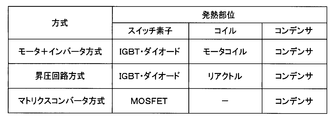
- the current generator When the current generator generates a ripple current by the motor + inverter system, the current generator configures a circuit including an IGBT, a diode, a motor coil, and a capacitor as a heat generating part.
- the operation of the motor + inverter system is the same as in the first embodiment.
- the current generator When the current generator generates a ripple current by a booster circuit system, the current generator is a system in which a circuit including an IGBT, a diode, a reactor, and a capacitor is formed as a heat generating part, and the high voltage side IGBT and the low voltage side IGBT are in series. Connected. A capacitor is connected in parallel to the series connection of the high voltage side IGBT and the low voltage side IGBT. A reactor is connected to the connection point of each IGBT. Each IGBT includes a diode. Secondary battery 10 is connected between the reactor and the low-voltage IGBT.
- the low-voltage side IGBT When boosting, the low-voltage side IGBT is turned on, a current is passed through the secondary battery 10 ⁇ reactor ⁇ low-voltage side IGBT, and energy is stored in the reactor. Thereafter, the low voltage side IGBT is turned off, and a current is passed through the battery, the reactor, the diode of the high voltage side IGBT, and the capacitor. Since the voltage on the secondary battery 10 side of the reactor is the voltage of the secondary battery 10, the boosted voltage is stored in the capacitor.
- the high-voltage side IGBT is turned on, and a current is passed through the capacitor ⁇ high-voltage side IGBT ⁇ reactor ⁇ secondary battery 10 to store energy in the reactor. Thereafter, the high voltage side IGBT is turned off, and a current is passed through the diode of the reactor ⁇ the secondary battery 10 ⁇ the low voltage side IGBT. Since the voltage on the diode side of the low voltage side IGBT of the reactor becomes 0V, the stepped down voltage is stored in the secondary battery 10.
- a ripple current is passed through the secondary battery 10 by repeating the above step-up and step-down.
- the temperature of the secondary battery 10 rises due to internal heat generation of the secondary battery 10.
- the direction of the secondary battery 10 ⁇ reactor is positive, the current flows in the positive direction when boosting, and the current flows in the reverse direction when decreasing.
- the current generator when the current generator generates a ripple current by the matrix converter method, the current generator constitutes a circuit including a MOSFET switch and a capacitor as a heat generating part.
- the secondary battery 10 constitutes a module including a MOSFET switch and a capacitor.
- the MOSFET switch opens and closes between the positive electrode of the battery cell 11 and one terminal of the in-module capacitor.
- the MOSFET switch opens and closes between the negative electrode of the battery cell 11 and the other terminal of the in-module capacitor.
- the temperature of the secondary battery 10 When the temperature of the secondary battery 10 is low, according to the switching operation of the MOSFET switch, some electric energy of the battery cell 11 is discharged to the capacitor in the secondary battery 10 to store the energy stored in the capacitor in the secondary battery 10. To charge some of the battery cells 11. That is, when the battery cell 11 is repeatedly charged and discharged, the temperature of the secondary battery 10 can be increased by heat generated by the internal resistance.
- boost circuit type IGBT and diode, and the matrix converter type MOSFET switch of the present embodiment correspond to the current switching means. Further, a booster circuit type reactor and capacitor, and a matrix converter type capacitor correspond to the power storage means.
- the heat of the cooling water is transferred to the refrigerant circulating through the heat pump circuit 28 through the chiller 27.
- the heat of the secondary battery 10 after the ripple temperature rise control can be used for air conditioning control.
- the battery temperature adjustment device 1 may be configured such that the refrigerant of the heat pump circuit 28 passes through the secondary battery 10. Thereby, the heat of the secondary battery 10 can be directly transferred to the heat pump circuit 28.
- FIG. 11 in the secondary battery 10, a first assembled battery 15a, a second assembled battery 15b, and a third assembled battery 15c, in which a plurality of battery cells 11 are connected in series, are connected in parallel. Switches 16a to 16c are connected in series to the assembled batteries 15a to 15c. The switches 16a to 16c are controlled by the control device 70.
- the supply of power from the first assembled battery 15a to the inverter 45 and the motor generator 46 is interrupted by the first switch 16a.
- the power supply from the second assembled battery 15b to the inverter 45 and the motor generator 46 is interrupted by the second switch 16b.
- the power supply from the third assembled battery 15c to the inverter 45 and the motor generator 46 is interrupted by the third switch 16c.
- the battery flow path 42 of the low-temperature cooling water circuit 40 includes a first battery flow path 42a, a second battery flow path 42b, and a third battery flow path 42c corresponding to each of the assembled batteries 15a to 15c. Yes.
- Each of the battery channels 42a to 42c is a cooling water channel through which the cooling water of the low-temperature cooling water circuit 40 flows.
- the first battery pack 15a is disposed in the first battery channel 42a.
- the temperature of the first assembled battery 15a is adjusted by the cooling water flowing through the first battery channel 42a.
- a first on-off valve 61a is disposed in the first battery channel 42a.
- the first on-off valve 61a is an electromagnetic valve that opens and closes the first battery channel 42a.
- the second battery pack 15b is disposed in the second battery channel 42b.
- the temperature of the second assembled battery 15b is adjusted by the cooling water flowing through the second battery channel 42b.
- a second on-off valve 61b is disposed in the second battery channel 42b.
- the second on-off valve 61b is an electromagnetic valve that opens and closes the second battery channel 42b.
- the third battery pack 15c is disposed in the third battery flow path 42c.
- the temperature of the third assembled battery 15c is adjusted by the cooling water flowing through the third battery channel 42c.
- a third on-off valve 61c is disposed in the third battery channel 42c.
- the third on-off valve 61c is an electromagnetic valve that opens and closes the third battery channel 42c.
- the cooling water in the low temperature side circulation channel 41 flows into the battery channels 42a to 42c, and the cooling water in the battery channels 42a to 42c is on the low temperature side.
- the cooling water circulates through the battery channels 42a to 42c.
- the circulation of the cooling water with respect to each of the battery flow paths 42a to 42c can be arbitrarily interrupted by the open / close control of each of the on / off valves 61a to 61c.
- the first assembled battery 15a is covered with the heat insulating portion 12. Thereby, a part of the secondary battery 10 can be subjected to ripple temperature rise control.
- cooling water or refrigerant is used as the heat medium, but various media such as oil may be used as the heat medium.
- a chlorofluorocarbon refrigerant is used as the refrigerant.
- the type of the refrigerant is not limited to this, and a natural refrigerant such as carbon dioxide, a hydrocarbon refrigerant, or the like may be used. good.
- the refrigeration cycle apparatus 20 of the above embodiment constitutes a subcritical refrigeration cycle in which the high-pressure side refrigerant pressure does not exceed the critical pressure of the refrigerant, but constitutes a supercritical refrigeration cycle in which the high-pressure side refrigerant pressure exceeds the critical pressure of the refrigerant. You may do it.
- the inlet side of the branch portion 23 a is connected to the outlet of the refrigerant passage of the high temperature side water-refrigerant heat exchanger 22, but it expands to the outlet of the refrigerant passage of the high temperature side water-refrigerant heat exchanger 22.
- a valve may be connected, and an outdoor unit may be connected to the expansion valve.
- An outdoor unit is connected to the inlet side of the branch part 23a.
- the battery temperature control device 1 is mounted on an electric vehicle.
- the battery temperature control device 1 is mounted on a hybrid vehicle that obtains driving force for vehicle travel from an internal combustion engine and a travel electric motor. Also good.
- the battery temperature control apparatus 1 is not restricted to vehicles, You may apply to the secondary batteries 10 other than vehicles.
- the ejector may be built in the indoor evaporator 25 of the above embodiment.
- the ejector sucks the fluid from the fluid suction port by the suction action of the high-speed jet fluid ejected from the nozzle.
- the ejector further increases the pressure of the mixed fluid by converting the velocity energy of the mixed fluid of the ejected fluid and the suction fluid sucked from the fluid suction port into pressure energy at the boosting unit.
- the booster is a so-called diffuser.
- the compressor 21 of the above embodiment may be a gas injection compressor.
- the gas injection compressor is a compressor that improves the compression efficiency by joining the intermediate pressure refrigerant generated in the cycle with the intermediate pressure refrigerant in the pressurization process and increasing the pressure of the refrigerant in multiple stages.
Abstract
A battery temperature adjustment device (1) controls charging/discharging of a secondary battery that can be charged/discharged, whereby the secondary battery self-generates heat due to a ripple current flowing in the secondary battery. The battery temperature adjustment device includes a heat-insulating part (12). The heat-insulating part is disposed on the outer side of the secondary battery. The heat-insulating part insulates heat discharged from the secondary battery. According to this configuration, due to the heat-insulating part, heat from the secondary battery does not readily escape to the external environment. Therefore, it is possible to suppress radiant heat loss in ripple temperature increase in the secondary battery.
Description
本出願は、2018年4月27日に出願された日本特許出願2018-86329号に基づくもので、ここにその記載内容を援用する。
This application is based on Japanese Patent Application No. 2018-86329 filed on Apr. 27, 2018, the contents of which are incorporated herein by reference.
本開示は、電池温調装置に関する。
The present disclosure relates to a battery temperature control device.
一般に、温度が過度に低下した2次電池は最大出力が著しく低下するので、負荷に対する十分な電力を供給することが困難である。このため、2次電池の加熱が必要になる。しかし、2次電池が持つ電気エネルギを用いて2次電池そのものを加熱する場合、2次電池単独では十分な出力を得ることができず、迅速な加熱が困難であった。
Generally, since the maximum output of a secondary battery whose temperature is excessively lowered is significantly reduced, it is difficult to supply sufficient power to the load. For this reason, the secondary battery needs to be heated. However, when the secondary battery itself is heated using electric energy possessed by the secondary battery, the secondary battery alone cannot obtain a sufficient output, and rapid heating is difficult.
そこで、外部回路を用いて2次電池の充放電を繰り返すことにより、出力が著しく低下した2次電池に大電流を発生させ、2次電池の内部抵抗による自己発熱で昇温する技術が、例えば特許文献1で提案されている。
Therefore, a technique for generating a large current in a secondary battery whose output has been significantly reduced by repeatedly charging and discharging the secondary battery using an external circuit and raising the temperature by self-heating due to the internal resistance of the secondary battery is, for example, This is proposed in Patent Document 1.
しかしながら、上記従来の技術のように、2次電池の充放電を繰り返すリップル昇温の方法を用いて2次電池を加熱する場合、リップル昇温によって発生した熱の一部が2次電池から外部環境に放熱される。このため、放熱ロスが生じてしまう。
However, when the secondary battery is heated using a ripple temperature rising method that repeats charging and discharging of the secondary battery as in the conventional technique, a part of the heat generated by the ripple temperature rising is external from the secondary battery. Heat is released to the environment. For this reason, a heat dissipation loss occurs.
本開示は、2次電池のリップル昇温における放熱ロスを抑制することができる電池温調装置を提供することを目的とする。
This disclosure aims to provide a battery temperature control device that can suppress heat dissipation loss due to a ripple temperature increase of a secondary battery.
本開示の第1態様及び第2態様による電池温調装置は、充放電可能な2次電池の充放電を制御することで2次電池に流れるリップル電流によって2次電池を自己発熱させる装置である。
The battery temperature control apparatus according to the first aspect and the second aspect of the present disclosure is an apparatus that self-heats a secondary battery by a ripple current flowing in the secondary battery by controlling charge / discharge of the chargeable / dischargeable secondary battery. .
本開示の第1態様による電池温調装置は、2次電池の外側に配置され、2次電池から放出される熱を断熱する断熱部を含む。
The battery temperature control device according to the first aspect of the present disclosure includes a heat insulating portion that is disposed outside the secondary battery and insulates heat released from the secondary battery.
これによると、2次電池の熱が断熱部によって外部環境に逃げにくくなる。したがって、2次電池のリップル昇温における放熱ロスを抑制することができる。
According to this, it becomes difficult for the heat of the secondary battery to escape to the external environment by the heat insulating part. Therefore, it is possible to suppress heat dissipation loss due to ripple temperature rise of the secondary battery.
本開示の第2態様による電池温調装置は、2次電池から放出される熱を蓄熱する蓄熱部を含む。
The battery temperature control device according to the second aspect of the present disclosure includes a heat storage unit that stores heat released from the secondary battery.
これによると、2次電池の熱が蓄熱部に蓄熱され外部環境に逃げにくくなり、一旦蓄熱した熱エネルギを2次電池やその他の機器で利用することができる。したがって、2次電池のリップル昇温における放熱ロスを抑制することができる。
According to this, the heat of the secondary battery is stored in the heat storage part and is difficult to escape to the external environment, and the heat energy once stored can be used in the secondary battery and other devices. Therefore, it is possible to suppress heat dissipation loss due to ripple temperature rise of the secondary battery.
本開示の第3態様による電池温調装置は、電流発生装置と熱媒体回路とを含む。電流発生装置は、充放電可能な2次電池の充放電を制御することで2次電池に流れるリップル電流によって2次電池を自己発熱させる。熱媒体回路は、熱媒体が循環すると共に、電流発生装置で発生する熱を熱媒体で受け取る。
The battery temperature control device according to the third aspect of the present disclosure includes a current generator and a heat medium circuit. The current generator controls the charge / discharge of the chargeable / dischargeable secondary battery to self-heat the secondary battery by the ripple current flowing through the secondary battery. The heat medium circuit circulates the heat medium and receives heat generated by the current generator with the heat medium.
これによると、電流発生装置で発生する熱が、熱媒体回路に受け渡されるので、リップル電流を発生させるために生じる熱を熱媒体回路において利用することができる。したがって、2次電池のリップル昇温における放熱ロスを抑制することができる。
According to this, since the heat generated by the current generator is transferred to the heat medium circuit, the heat generated to generate the ripple current can be used in the heat medium circuit. Therefore, it is possible to suppress heat dissipation loss due to ripple temperature rise of the secondary battery.
本開示についての上記及び他の目的、特徴や利点は、添付図面を参照した下記詳細な説明から、より明確になる。添付図面において、
図1は、第1実施形態に係る電池温調装置を示した図であり、
図2は、インバータの回路図であり、
図3は、電池温調装置に含まれる制御装置を説明するための図であり、
図4は、断熱部の効果を説明するための図であり、
図5は、第2実施形態に係る2次電池を示した図であり、
図6は、第3実施形態に係る2次電池を示した図であり、
図7は、第4実施形態に係る電池温調装置の一部を示した図であり、
図8は、第4実施形態に係るインバータの駆動方式を示した図であり、
図9は、第5実施形態に係る電池温調装置の一部を示した図であり、
図10は、第6実施形態に係る電池温調装置の一部を示した図であり、
図11は、第7実施形態に係る電池温調装置を示した図である。
The above and other objects, features, and advantages of the present disclosure will become more apparent from the following detailed description with reference to the accompanying drawings. In the accompanying drawings,
FIG. 1 is a diagram showing a battery temperature control device according to the first embodiment. FIG. 2 is a circuit diagram of the inverter. FIG. 3 is a diagram for explaining a control device included in the battery temperature control device, FIG. 4 is a diagram for explaining the effect of the heat insulating portion. FIG. 5 is a diagram illustrating a secondary battery according to the second embodiment. FIG. 6 is a diagram illustrating a secondary battery according to the third embodiment. FIG. 7 is a view showing a part of the battery temperature control device according to the fourth embodiment, FIG. 8 is a diagram illustrating an inverter driving method according to the fourth embodiment. FIG. 9 is a view showing a part of the battery temperature control device according to the fifth embodiment, FIG. 10 is a diagram showing a part of the battery temperature control device according to the sixth embodiment, FIG. 11 is a diagram showing a battery temperature control device according to the seventh embodiment.
以下に、図面を参照しながら本開示を実施するための複数の形態を説明する。各実施形態において先行する実施形態で説明した事項に対応する部分には同一の参照符号を付して重複する説明を省略する場合がある。各実施形態において構成の一部のみを説明している場合は、構成の他の部分については先行して説明した他の実施形態を適用することができる。各実施形態で具体的に組合せが可能であることを明示している部分同士の組合せばかりではなく、特に組合せに支障が生じなければ、明示してなくとも実施形態同士を部分的に組み合せることも可能である。
Hereinafter, a plurality of modes for carrying out the present disclosure will be described with reference to the drawings. In each embodiment, portions corresponding to those described in the preceding embodiment may be denoted by the same reference numerals, and redundant description may be omitted. When only a part of the configuration is described in each embodiment, the other embodiments described above can be applied to other parts of the configuration. Not only combinations of parts that clearly show that combinations are possible in each embodiment, but also combinations of the embodiments even if they are not explicitly stated unless there is a problem with the combination. Is also possible.
(第1実施形態)
以下、実施形態について図に基づいて説明する。図1に示された電池温調装置1は、車両に搭載された2次電池10を適切な温度に調整する装置である。電池温調装置1は、2次電池10の充放電を制御することで2次電池10に流れるリップル電流によって2次電池10を自己発熱させる装置である。また、電池温調装置1は、車室内空間を適切な温度に調整する空調装置としても機能する。 (First embodiment)
Hereinafter, embodiments will be described with reference to the drawings. A batterytemperature control device 1 shown in FIG. 1 is a device that adjusts a secondary battery 10 mounted on a vehicle to an appropriate temperature. The battery temperature control device 1 is a device that self-heats the secondary battery 10 by a ripple current flowing through the secondary battery 10 by controlling charging and discharging of the secondary battery 10. The battery temperature control device 1 also functions as an air conditioner that adjusts the interior space of the vehicle to an appropriate temperature.
以下、実施形態について図に基づいて説明する。図1に示された電池温調装置1は、車両に搭載された2次電池10を適切な温度に調整する装置である。電池温調装置1は、2次電池10の充放電を制御することで2次電池10に流れるリップル電流によって2次電池10を自己発熱させる装置である。また、電池温調装置1は、車室内空間を適切な温度に調整する空調装置としても機能する。 (First embodiment)
Hereinafter, embodiments will be described with reference to the drawings. A battery
電池温調装置1は、走行用電動モータから車両走行用の駆動力を得る電気自動車に搭載される。電気自動車は、車両停車時に外部電源から供給された電力を、車両に搭載された2次電池10に充電可能となっている。外部電源は例えば商用電源である。2次電池10に蓄えられた電力は、走行用電動モータのみならず、電池温調装置1を構成する電動式構成機器をはじめとする各種車載機器に供給される。
The battery temperature control device 1 is mounted on an electric vehicle that obtains a driving force for driving a vehicle from an electric motor for driving. The electric vehicle can charge the secondary battery 10 mounted on the vehicle with electric power supplied from an external power source when the vehicle is stopped. The external power source is, for example, a commercial power source. The electric power stored in the secondary battery 10 is supplied not only to the electric motor for traveling but also to various in-vehicle devices including the electric components constituting the battery temperature control device 1.
2次電池10は、充放電可能な複数の電池セル11を有する。各電池セル11としては、例えばリチウムイオン電池を用いることができる。この種の電池は、低温になると化学反応が進みにくく充放電に関して十分な性能を発揮することができない。一方、この種の電池は、高温になると劣化が進行しやすい。したがって、各電池セル11の温度は、充分な性能を発揮できる適正な温度の範囲内に調整される。
The secondary battery 10 has a plurality of chargeable / dischargeable battery cells 11. As each battery cell 11, a lithium ion battery can be used, for example. When this type of battery is at a low temperature, the chemical reaction is difficult to proceed, and sufficient performance with respect to charging and discharging cannot be exhibited. On the other hand, this type of battery is likely to deteriorate at a high temperature. Therefore, the temperature of each battery cell 11 is adjusted within an appropriate temperature range that can exhibit sufficient performance.
また、電池温調装置1は、2次電池10から放出される熱を断熱するための断熱部12を有する。断熱部12として、例えば真空断熱材、グラスウール、発泡ポリウレタン等の材料が用いられる。
Moreover, the battery temperature control apparatus 1 has a heat insulating part 12 for insulating heat released from the secondary battery 10. For example, a material such as a vacuum heat insulating material, glass wool, or polyurethane foam is used as the heat insulating portion 12.
断熱部12は、2次電池10の外側に配置されている。断熱部12は、2次電池10の一部、または全体を覆っている。なお、配線は断熱部12を貫通している。
The heat insulating part 12 is disposed outside the secondary battery 10. The heat insulating part 12 covers a part or the whole of the secondary battery 10. The wiring penetrates the heat insulating portion 12.
電池温調装置1は、冷凍サイクル装置20を有する。以下、冷凍サイクル装置20を構成する各構成機器について説明する。
The battery temperature control device 1 has a refrigeration cycle device 20. Hereinafter, each component apparatus which comprises the refrigerating-cycle apparatus 20 is demonstrated.
圧縮機21は、冷凍サイクル装置20において、冷媒を吸入し、圧縮して吐出する。圧縮機21は、車両ボンネット内に配置されている。圧縮機21は、吐出容量が固定された固定容量型の圧縮機構を電動モータにて回転駆動する電動圧縮機である。圧縮機21は、後述する制御装置70から出力される制御信号によって、回転数(すなわち冷媒吐出能力)が制御される。
Compressor 21 draws in refrigerant in refrigeration cycle apparatus 20, compresses it, and discharges it. The compressor 21 is arrange | positioned in the vehicle bonnet. The compressor 21 is an electric compressor that rotationally drives a fixed capacity type compression mechanism with a fixed discharge capacity by an electric motor. The rotation speed (that is, the refrigerant discharge capacity) of the compressor 21 is controlled by a control signal output from the control device 70 described later.
圧縮機21の吐出口には、高温側水-冷媒熱交換器22の冷媒通路の入口側が接続されている。高温側水-冷媒熱交換器22は、圧縮機21から吐出された高圧冷媒と高温冷却水回路30を循環する高温側熱媒体とを熱交換させて、高温側熱媒体を加熱する熱交換器である。高温側熱媒体としては、エチレングリコールを含む溶液、不凍液等を採用することができる。
The inlet side of the refrigerant passage of the high temperature side water-refrigerant heat exchanger 22 is connected to the discharge port of the compressor 21. The high temperature side water-refrigerant heat exchanger 22 heat-exchanges the high pressure refrigerant discharged from the compressor 21 and the high temperature side heat medium circulating in the high temperature cooling water circuit 30 to heat the high temperature side heat medium. It is. As the high temperature side heat medium, a solution containing ethylene glycol, an antifreeze solution, or the like can be used.
ここで、高温冷却水回路30は、高温側熱媒体を循環させる高温側の水回路である。高温冷却水回路30は、高温側循環流路31を有する。高温側循環流路31は、高温側熱媒体として高温側冷却水が循環する冷却水流路である。高温側循環流路31には、高温側水-冷媒熱交換器22の水通路、高温側ラジエータ32、高温側ポンプ33、高温側電気ヒータ34、高温側ヒータコア35等が配置されている。
Here, the high-temperature cooling water circuit 30 is a high-temperature side water circuit that circulates the high-temperature side heat medium. The high temperature coolant circuit 30 has a high temperature side circulation channel 31. The high temperature side circulation channel 31 is a cooling water channel through which high temperature side cooling water circulates as a high temperature side heat medium. In the high temperature side circulation channel 31, a water passage of the high temperature side water-refrigerant heat exchanger 22, a high temperature side radiator 32, a high temperature side pump 33, a high temperature side electric heater 34, a high temperature side heater core 35, and the like are arranged.
高温側ラジエータ32は、車両ボンネット内の前方側に配置されている。高温側ラジエータ32は、高温側水-冷媒熱交換器22等と一体的に形成されていても良い。高温側ラジエータ32は、高温側水-冷媒熱交換器22にて加熱された高温側熱媒体と図示しない外気ファンから送風された外気とを熱交換させて、高温側熱媒体の有する熱を外気に放熱させる熱交換器である。
The high temperature side radiator 32 is arranged on the front side in the vehicle bonnet. The high temperature side radiator 32 may be formed integrally with the high temperature side water-refrigerant heat exchanger 22 or the like. The high temperature side radiator 32 exchanges heat between the high temperature side heat medium heated by the high temperature side water-refrigerant heat exchanger 22 and the outside air blown from an outside air fan (not shown), and the heat of the high temperature side heat medium is transferred to the outside air. It is a heat exchanger that dissipates heat.
高温側ポンプ33は、高温冷却水回路30において、高温側熱媒体を高温側電気ヒータ34へ圧送する高温側水ポンプである。高温側ポンプ33は、制御装置70から出力される制御電圧によって、回転数(すなわち水圧送能力)が制御される電動ポンプである。
The high temperature side pump 33 is a high temperature side water pump that pumps the high temperature side heat medium to the high temperature side electric heater 34 in the high temperature cooling water circuit 30. The high temperature side pump 33 is an electric pump in which the rotation speed (that is, the water pressure feeding capacity) is controlled by the control voltage output from the control device 70.
高温側電気ヒータ34は、電力が供給されることによって発熱し、高温側ポンプ33から圧送される高温冷却水回路30の高温側熱媒体を加熱する補助加熱器である。
The high temperature side electric heater 34 is an auxiliary heater that generates heat when electric power is supplied and heats the high temperature side heat medium of the high temperature cooling water circuit 30 that is pumped from the high temperature side pump 33.
高温側ヒータコア35は、後述する空調ケーシング内に配置されている。高温側ヒータコア35は、高温側電気ヒータ34にて加熱された高温側熱媒体と送風空気とを熱交換させて、送風空気を加熱する熱交換器である。
The high temperature side heater core 35 is disposed in an air conditioning casing which will be described later. The high temperature side heater core 35 is a heat exchanger that heats the blown air by exchanging heat between the high temperature side heat medium heated by the high temperature side electric heater 34 and the blown air.
つまり、本実施形態では、高温冷却水回路30に配置された高温側ポンプ33、高温側電気ヒータ34、高温側ヒータコア35、高温側水-冷媒熱交換器22等によって、圧縮機21から吐出された冷媒を熱源として送風空気を加熱する加熱部が構成されている。
That is, in the present embodiment, the high temperature side pump 33, the high temperature side electric heater 34, the high temperature side heater core 35, the high temperature side water-refrigerant heat exchanger 22 and the like disposed in the high temperature cooling water circuit 30 are discharged from the compressor 21. A heating unit is configured to heat the blown air using the refrigerant as a heat source.
なお、高温冷却水回路30は、高温側ラジエータ32に並列に接続された経路を有する。高温側ラジエータ32に並列に接続された経路は、高温側ラジエータ32を迂回する迂回経路である。迂回経路と高温側ラジエータ32の経路との分岐点には図示しないサーモスタット弁が設けられている。これにより、高温冷却水回路30の高温側熱媒体の温度に応じて、高温側熱媒体が高温側ラジエータ32の経路または迂回経路に流れる。
The high temperature cooling water circuit 30 has a path connected in parallel to the high temperature side radiator 32. The path connected in parallel to the high temperature side radiator 32 is a detour path that bypasses the high temperature side radiator 32. A thermostat valve (not shown) is provided at a branch point between the bypass path and the path of the high-temperature side radiator 32. Accordingly, the high temperature side heat medium flows through the path of the high temperature side radiator 32 or the detour path according to the temperature of the high temperature side heat medium of the high temperature cooling water circuit 30.
次に、高温側水-冷媒熱交換器22の冷媒通路の出口には、分岐部23aの流入口側が接続されている。分岐部23aは、高温側水-冷媒熱交換器22から流出した冷媒の流れを分岐する。分岐部23aは、互いに連通する3つの流入出口が有する三方継手構造を持つ。分岐部23aは、3つの流入出口のうち1つが冷媒流入口であり、残りの2つが冷媒流出口である。
Next, the outlet side of the branch portion 23 a is connected to the outlet of the refrigerant passage of the high temperature side water-refrigerant heat exchanger 22. The branch portion 23a branches the refrigerant flow that has flowed out of the high-temperature side water-refrigerant heat exchanger 22. The branch part 23a has a three-way joint structure with three inflow / outflow ports communicating with each other. In the branch portion 23a, one of the three inlets and outlets is a refrigerant inflow port, and the remaining two are refrigerant outlets.
なお、高温側水-冷媒熱交換器22の冷媒通路の出口には、レシーバが接続されていても良い。レシーバは、高温側水-冷媒熱交換器22から流出した高圧冷媒の気液を分離して分離された液相冷媒を下流側へ流出させると共に、サイクルの余剰冷媒を液相冷媒として貯える気液分離部である。レシーバは、有底筒状の容器である。レシーバは、高温側水-冷媒熱交換器22等と一体的に形成されていても良い。
A receiver may be connected to the outlet of the refrigerant passage of the high temperature side water-refrigerant heat exchanger 22. The receiver separates the gas-liquid of the high-pressure refrigerant that has flowed out of the high-temperature water-refrigerant heat exchanger 22 and causes the separated liquid-phase refrigerant to flow downstream, and stores the excess refrigerant in the cycle as the liquid-phase refrigerant. It is a separation part. The receiver is a bottomed cylindrical container. The receiver may be formed integrally with the high temperature side water-refrigerant heat exchanger 22 or the like.
分岐部23aの一方の流出口には、冷房用膨張弁24aの入口側が接続されている。分岐部23aの他方の流出口には、吸熱用膨張弁24bの入口側が接続されている。
The inlet side of the cooling expansion valve 24a is connected to one outlet of the branch portion 23a. An inlet side of the endothermic expansion valve 24b is connected to the other outlet of the branch portion 23a.
冷房用膨張弁24aは、少なくとも冷房モード時及び除湿暖房モード時に、高温側水-冷媒熱交換器22から流出した冷媒を減圧させる減圧部であると共に、室内蒸発器25へ流入する冷媒の流量を調整する冷房用流量調整部である。
The cooling expansion valve 24a is a pressure reducing unit that depressurizes the refrigerant flowing out of the high-temperature side water-refrigerant heat exchanger 22 at least in the cooling mode and the dehumidifying heating mode, and controls the flow rate of the refrigerant flowing into the indoor evaporator 25. This is a cooling flow rate adjusting unit to be adjusted.
冷房用膨張弁24aは、絞り開度を変更可能に構成された弁体と、弁体の開度を変化させる電動アクチュエータとを有して構成される電気式の可変絞り機構である。電動アクチュエータは、具体的には、ステッピングモータである。冷房用膨張弁24aは、制御装置70から出力される制御信号によって、その作動が制御される。制御信号は、例えば制御パルスである。冷房用膨張弁24aは、弁開度を全閉とすることで冷媒通路を閉塞する全閉機能を有する。
The cooling expansion valve 24a is an electric variable throttle mechanism that includes a valve body that can change the throttle opening degree and an electric actuator that changes the opening degree of the valve body. Specifically, the electric actuator is a stepping motor. The operation of the cooling expansion valve 24 a is controlled by a control signal output from the control device 70. The control signal is, for example, a control pulse. The cooling expansion valve 24a has a fully closed function of closing the refrigerant passage by closing the valve opening degree.
冷房用膨張弁24aの出口には、室内蒸発器25の冷媒入口側が接続されている。室内蒸発器25は、空調ケーシング内に配置されている。より詳細には、室内蒸発器25は、高温側ヒータコア35よりも送風空気流れ上流側に配置されている。
The refrigerant inlet side of the indoor evaporator 25 is connected to the outlet of the cooling expansion valve 24a. The indoor evaporator 25 is disposed in the air conditioning casing. More specifically, the indoor evaporator 25 is disposed on the upstream side of the blowing air flow with respect to the high temperature side heater core 35.
室内蒸発器25は、少なくとも冷房モード時及び除湿暖房モード時に、冷房用膨張弁24aにて減圧された低圧冷媒と送風空気とを熱交換させて低圧冷媒を蒸発させ、送風空気を冷却する冷却用蒸発部である。
The indoor evaporator 25 is a cooling unit that heat-exchanges the low-pressure refrigerant decompressed by the cooling expansion valve 24a and the blown air to evaporate the low-pressure refrigerant and cool the blown air at least in the cooling mode and the dehumidifying heating mode. It is an evaporation part.
室内蒸発器25の冷媒出口には、蒸発圧力調整弁26の入口側が接続されている。蒸発圧力調整弁26は、室内蒸発器25における冷媒蒸発圧力を予め定めた基準圧力以上に維持する蒸発圧力調整部である。蒸発圧力調整弁26は、室内蒸発器25の出口側の冷媒圧力の上昇に伴って、弁開度を増加させる機械式の可変絞り機構で構成されている。
The inlet side of the evaporation pressure adjusting valve 26 is connected to the refrigerant outlet of the indoor evaporator 25. The evaporation pressure adjusting valve 26 is an evaporation pressure adjusting unit that maintains the refrigerant evaporation pressure in the indoor evaporator 25 at or above a predetermined reference pressure. The evaporation pressure adjusting valve 26 is configured by a mechanical variable throttle mechanism that increases the valve opening as the refrigerant pressure on the outlet side of the indoor evaporator 25 increases.
本実施形態では、蒸発圧力調整弁26として、室内蒸発器25における冷媒蒸発温度を、室内蒸発器25の着霜を抑制可能な基準温度以上に維持するものを採用する。基準温度は、例えば1℃である。
In the present embodiment, an evaporating pressure adjusting valve 26 that maintains the refrigerant evaporating temperature in the indoor evaporator 25 at or above a reference temperature capable of suppressing frost formation in the indoor evaporator 25 is employed. The reference temperature is 1 ° C., for example.
蒸発圧力調整弁26の出口には、合流部23bの一方の流入口側が接続されている。合流部23bは、蒸発圧力調整弁26から流出した冷媒の流れとチラー27から流出した冷媒の流れとを合流させる。合流部23bの基本的構成は、分岐部23aと同様である。すなわち、合流部は、三方継手構造を持つ。合流部は、3つの流入出口のうち2つが冷媒流入口であり、残りの1つが冷媒流出口である。
The outlet of the evaporation pressure adjusting valve 26 is connected to one inlet side of the merging portion 23b. The junction 23 b joins the refrigerant flow that has flowed out of the evaporation pressure adjusting valve 26 and the refrigerant flow that has flowed out of the chiller 27. The basic configuration of the merging portion 23b is the same as that of the branching portion 23a. That is, the merge part has a three-way joint structure. Two of the three inlets and outlets are refrigerant inlets, and the remaining one is a refrigerant outlet.
吸熱用膨張弁24bは、少なくとも暖房モード時に、高温側水-冷媒熱交換器22から流出した冷媒を減圧させる減圧部であると共に、チラー27へ流入する冷媒の流量を調整する吸熱用流量調整部である。吸熱用膨張弁24bの基本的構成は、冷房用膨張弁24aと同様である。
The endothermic expansion valve 24b is a pressure reducing unit that depressurizes the refrigerant that has flowed out of the high-temperature side water-refrigerant heat exchanger 22 at least in the heating mode, and also adjusts the flow rate of the refrigerant that flows into the chiller 27. It is. The basic configuration of the endothermic expansion valve 24b is the same as that of the cooling expansion valve 24a.
吸熱用膨張弁24bの出口には、チラー27の冷媒通路の入口側が接続されている。チラー27は、少なくとも暖房モード時に、吸熱用膨張弁24bにて減圧された低圧冷媒と低温冷却水回路40を循環する低温側熱媒体とを熱交換させ、低圧冷媒を蒸発させて冷媒に吸熱作用を発揮させる吸熱用蒸発部である。低温側熱媒体としては、エチレングリコールを含む溶液、不凍液等を採用することができる。
The inlet side of the refrigerant passage of the chiller 27 is connected to the outlet of the endothermic expansion valve 24b. The chiller 27 exchanges heat between the low-pressure refrigerant decompressed by the endothermic expansion valve 24b and the low-temperature side heat medium circulating in the low-temperature cooling water circuit 40 at least in the heating mode, evaporates the low-pressure refrigerant, and absorbs heat to the refrigerant. Is an endothermic evaporation section that exhibits As the low-temperature heat medium, a solution containing ethylene glycol, an antifreeze solution, or the like can be used.
すなわち、冷凍サイクル装置20が構成する冷媒回路は、冷媒が循環することによって低温側である低温冷却水回路40から高温側である冷媒回路に熱をくみ上げるヒートポンプ回路28である。つまり、低温冷却水回路40を循環する冷却水の熱は、ヒートポンプ回路28を循環する冷媒に受け渡される。チラー27は、冷却水から冷媒に吸熱させる。このように、冷却水の熱は、チラー27を介して低温冷却水回路40からヒートポンプ回路28に受け渡される。
That is, the refrigerant circuit formed by the refrigeration cycle apparatus 20 is a heat pump circuit 28 that draws heat from the low-temperature cooling water circuit 40 on the low temperature side to the refrigerant circuit on the high temperature side by circulating the refrigerant. That is, the heat of the cooling water circulating through the low-temperature cooling water circuit 40 is transferred to the refrigerant circulating through the heat pump circuit 28. The chiller 27 absorbs heat from the cooling water to the refrigerant. Thus, the heat of the cooling water is transferred from the low-temperature cooling water circuit 40 to the heat pump circuit 28 via the chiller 27.
チラー27の冷媒通路の出口には、合流部23bの他方の流入口側が接続されている。合流部23bの流出口には、圧縮機21の吸入口側が接続されている。
The other inlet side of the merging portion 23b is connected to the outlet of the refrigerant passage of the chiller 27. The suction port side of the compressor 21 is connected to the outlet of the junction 23b.
ここで、低温冷却水回路40は、低温側熱媒体を循環させる低温側の水回路である。低温冷却水回路40は、低温側循環流路41及び電池流路42を有する。低温側循環流路41は、低温側熱媒体として低温側冷却水が循環する流路である。低温側循環流路41には、低温側ポンプ43、チラー27、低温側電気ヒータ44、インバータ45、モータジェネレータ46、及び低温側ラジエータ47が配置されている。
Here, the low-temperature cooling water circuit 40 is a low-temperature side water circuit for circulating the low-temperature side heat medium. The low temperature cooling water circuit 40 includes a low temperature side circulation channel 41 and a battery channel 42. The low temperature side circulation channel 41 is a channel through which low temperature side cooling water circulates as a low temperature side heat medium. In the low temperature side circulation passage 41, a low temperature side pump 43, a chiller 27, a low temperature side electric heater 44, an inverter 45, a motor generator 46, and a low temperature side radiator 47 are arranged.
低温側ポンプ43は、低温冷却水回路40において、低温側熱媒体をチラー27の水通路の入口側へ圧送する低温側水ポンプである。低温側ポンプ43の基本的構成は、高温側ポンプ33と同様である。
The low temperature side pump 43 is a low temperature side water pump that pumps the low temperature side heat medium to the inlet side of the water passage of the chiller 27 in the low temperature cooling water circuit 40. The basic configuration of the low temperature side pump 43 is the same as that of the high temperature side pump 33.
低温側電気ヒータ44は、電力が供給されることによって発熱し、低温冷却水回路40の冷却水を加熱する補助加熱器である。
The low temperature side electric heater 44 is an auxiliary heater that generates heat when electric power is supplied and heats the cooling water of the low temperature cooling water circuit 40.
インバータ45は、2次電池10から供給された直流電力を交流電力に変換してモータジェネレータ46に出力する電力変換装置である。モータジェネレータ46は、インバータ45から出力された電力を利用して走行用駆動力を発生すると共に、減速中や降坂中に回生電力を発生させる。インバータ45及びモータジェネレータ46は、低温冷却水回路40の冷却水によって、十分な性能を発揮できる適正な温度帯の範囲内に調整される。
The inverter 45 is a power conversion device that converts DC power supplied from the secondary battery 10 into AC power and outputs the AC power to the motor generator 46. The motor generator 46 uses the electric power output from the inverter 45 to generate a driving force for traveling and also generates regenerative electric power during deceleration or downhill. The inverter 45 and the motor generator 46 are adjusted by the cooling water of the low-temperature cooling water circuit 40 within an appropriate temperature range in which sufficient performance can be exhibited.
図2に示されるように、モータジェネレータ46は、例えば、U相、V相、W相の3つのコイルが中性点で連結された3相回転機である。モータジェネレータ46のうち中性点側ではない各端子は、インバータ45を介して2次電池10に接続されている。
As shown in FIG. 2, the motor generator 46 is a three-phase rotating machine in which, for example, three coils of a U phase, a V phase, and a W phase are connected at a neutral point. Terminals that are not on the neutral point side of the motor generator 46 are connected to the secondary battery 10 via the inverter 45.
インバータ45は、U相、V相、W相の3相の交流の電圧及び電流を発生させて高電圧のモータジェネレータ46を駆動する。このため、インバータ45は、U相アーム48、V相アーム49、W相アーム50を有する。これら各アーム48~50は、正極側配線51と負極側配線52との間に並列に接続されている。
The inverter 45 generates a three-phase AC voltage and current of U phase, V phase, and W phase to drive the high voltage motor generator 46. Therefore, inverter 45 has U-phase arm 48, V-phase arm 49, and W-phase arm 50. These arms 48 to 50 are connected in parallel between the positive electrode side wiring 51 and the negative electrode side wiring 52.
各アーム48~50は、直列に接続された2つのスイッチング素子53、54を有する。第1スイッチング素子53は、正極側配線51に接続されている。第2スイッチング素子54は、第1スイッチング素子53と負極側配線52との間に接続されている。
Each arm 48 to 50 has two switching elements 53 and 54 connected in series. The first switching element 53 is connected to the positive electrode side wiring 51. The second switching element 54 is connected between the first switching element 53 and the negative electrode side wiring 52.
各スイッチング素子53、54のコレクタ-エミッタ間には、エミッタ側からコレクタ側へ電流を流すダイオード55がそれぞれ接続されている。また、各スイッチング素子53、54の接続点は、モータジェネレータ46の各端子に接続されている。各スイッチング素子53、54は例えばIGBT(Insulated Gate Bipolar Transistor)である。各ダイオード55はFWD(Free Wheeling Diode)である。
A diode 55 is connected between the collector and emitter of each of the switching elements 53 and 54 to allow current to flow from the emitter side to the collector side. The connection points of the switching elements 53 and 54 are connected to the terminals of the motor generator 46. Each of the switching elements 53 and 54 is, for example, an IGBT (Insulated Gate Gate Bipolar Transistor). Each diode 55 is an FWD (Free Wheeling Diode).
インバータ45の正極側配線51には、リレー56を介して2次電池10の正極が接続されている。また、インバータ45の正極側配線51と負極側配線52との間には平滑コンデンサ57が接続されている。
The positive electrode of the secondary battery 10 is connected to the positive electrode side wiring 51 of the inverter 45 through the relay 56. Further, a smoothing capacitor 57 is connected between the positive electrode side wiring 51 and the negative electrode side wiring 52 of the inverter 45.
2次電池10の正極は、リレー58を介してU相に対応した各スイッチング素子53、54の接続点に接続されている。リレー56、58として、例えば可動接点形の電磁形リレーが用いられる。各スイッチング素子53、54及び各リレー56、58は後述する制御装置70からの操作信号によって電子操作される。
The positive electrode of the secondary battery 10 is connected via a relay 58 to a connection point of the switching elements 53 and 54 corresponding to the U phase. As the relays 56 and 58, for example, movable contact type electromagnetic relays are used. The switching elements 53 and 54 and the relays 56 and 58 are electronically operated by an operation signal from a control device 70 described later.
低温側ラジエータ47は、チラー27等と一体的に形成されて、車両ボンネット内の前方側に配置されている。低温側ラジエータ47は、チラー27にて冷却された低温側熱媒体と外気ファンから送風された外気とを熱交換させて、低温側熱媒体に外気から吸熱させる熱交換器である。
The low temperature side radiator 47 is formed integrally with the chiller 27 and the like, and is disposed on the front side in the vehicle bonnet. The low temperature side radiator 47 is a heat exchanger that exchanges heat between the low temperature side heat medium cooled by the chiller 27 and the outside air blown from the outside air fan, and causes the low temperature side heat medium to absorb heat from the outside air.
なお、低温冷却水回路40は、低温側ラジエータ47に並列に接続された経路を有する。低温側ラジエータ47に並列に接続された経路は、低温側ラジエータ47を迂回する迂回経路である。迂回経路と低温側ラジエータ47の経路との分岐点には図示しないサーモスタット弁が設けられている。これにより、低温冷却水回路40の低温側熱媒体の温度に応じて、低温側熱媒体が低温側ラジエータ47の経路または迂回経路に流れる。
Note that the low-temperature cooling water circuit 40 has a path connected in parallel to the low-temperature side radiator 47. The path connected in parallel to the low temperature side radiator 47 is a detour path that bypasses the low temperature side radiator 47. A thermostat valve (not shown) is provided at a branch point between the bypass path and the path of the low-temperature side radiator 47. Accordingly, the low temperature side heat medium flows through the path of the low temperature side radiator 47 or the detour path according to the temperature of the low temperature side heat medium of the low temperature cooling water circuit 40.
低温側循環流路41と電池流路42との接続部には、第1三方弁59及び第2三方弁60が配置されている。第1三方弁59は、低温側循環流路41の冷却水が電池流路42に流入する状態と流入しない状態とを切り替える電磁弁である。第2三方弁60は、電池流路42の冷却水が低温側循環流路41へ流出する状態と流出しない状態とを切り替える電磁弁である。よって、低温冷却水回路40は、2次電池10の熱を熱媒体である冷却水で受け取る熱媒体回路であると言える。同様に、冷凍サイクル装置20が構成する冷媒回路は、チラー27を介して冷却水の熱を熱媒体である冷媒で受け取る熱媒体回路であると言える。
A first three-way valve 59 and a second three-way valve 60 are arranged at a connection portion between the low temperature side circulation channel 41 and the battery channel 42. The first three-way valve 59 is an electromagnetic valve that switches between a state in which the cooling water of the low-temperature side circulation passage 41 flows into the battery passage 42 and a state in which the cooling water does not flow into the battery passage 42. The second three-way valve 60 is an electromagnetic valve that switches between a state in which the cooling water in the battery passage 42 flows out to the low temperature side circulation passage 41 and a state in which it does not flow out. Therefore, it can be said that the low-temperature cooling water circuit 40 is a heat medium circuit that receives the heat of the secondary battery 10 with the cooling water that is the heat medium. Similarly, the refrigerant circuit formed by the refrigeration cycle apparatus 20 can be said to be a heat medium circuit that receives the heat of the cooling water with the refrigerant that is the heat medium via the chiller 27.
上記の構成において、室内蒸発器25及び高温側ヒータコア35は、図示しない空調ケーシングに収容される。高温側ヒータコア35は、空調ケーシング内の空気通路において、室内蒸発器25の空気流れ下流側に配置される。空調ケーシングには内気及び外気が切り替え導入される。空調ケーシングに導入された内気及び外気は、図示しない送風機によって室内蒸発器25及び高温側ヒータコア35に送風される。
In the above configuration, the indoor evaporator 25 and the high temperature side heater core 35 are accommodated in an air conditioning casing (not shown). The high temperature side heater core 35 is disposed on the downstream side of the air flow of the indoor evaporator 25 in the air passage in the air conditioning casing. Inside air and outside air are switched and introduced into the air conditioning casing. The inside air and outside air introduced into the air conditioning casing are blown to the indoor evaporator 25 and the high temperature side heater core 35 by a blower (not shown).
空調ケーシング内の空気通路において室内蒸発器25と高温側ヒータコア35との間には、図示しないエアミックスドアが配置されている。エアミックスドアは、室内蒸発器25を通過した冷風のうち高温側ヒータコア35に流入する冷風と、高温側ヒータコア35をバイパスして流れる冷風との風量割合を調整する。
An air mix door (not shown) is disposed between the indoor evaporator 25 and the high temperature side heater core 35 in the air passage in the air conditioning casing. The air mix door adjusts the air volume ratio between the cool air that has passed through the indoor evaporator 25 and that flows into the high-temperature heater core 35 and the cool air that bypasses the high-temperature heater core 35.
エアミックスドアによって温度調整された空調風は、空調ケーシングに形成された図示しない吹出口から車室内へ吹き出される。
The conditioned air whose temperature has been adjusted by the air mix door is blown into the passenger compartment from an unillustrated air outlet formed in the air conditioning casing.
上記の電池温調装置1は図3に示された制御装置70によって制御される。制御装置70は、CPU、ROM、RAM等を含む周知のマイクロコンピュータとその周辺回路を有する。制御装置70は、ROMに記憶された制御プログラムに従って、空調制御、2次電池10の温度制御、2次電池10の昇温制御等を行う。
The battery temperature control device 1 is controlled by the control device 70 shown in FIG. The control device 70 includes a well-known microcomputer including a CPU, a ROM, a RAM, and the like and peripheral circuits thereof. The control device 70 performs air conditioning control, temperature control of the secondary battery 10, temperature increase control of the secondary battery 10, and the like according to a control program stored in the ROM.
制御装置70の入力側には、電池温度センサ13や図示しない各種スイッチが接続されている。電池温度センサ13は、2次電池10の温度を検出するセンサである。各種スイッチは、車内空調に関するスイッチである。制御装置70の出力側には、圧縮機21、冷房用膨張弁24a、吸熱用膨張弁24b、高温側ポンプ33、低温側ポンプ43、第1三方弁59、第2三方弁60等の制御対象機器が接続されている。制御装置70は、これらの制御対象機器の動作を制御する。
The battery temperature sensor 13 and various switches (not shown) are connected to the input side of the control device 70. The battery temperature sensor 13 is a sensor that detects the temperature of the secondary battery 10. The various switches are switches related to in-vehicle air conditioning. On the output side of the control device 70, the compressor 21, the cooling expansion valve 24 a, the endothermic expansion valve 24 b, the high temperature side pump 33, the low temperature side pump 43, the first three-way valve 59, the second three-way valve 60, etc. The device is connected. The control device 70 controls the operation of these controlled devices.
次に、電池温調装置1の空調制御について説明する。冷凍サイクル装置20の低圧側冷媒が室内蒸発器25を流れるので、車室内へ送風される空気が室内蒸発器25で冷却される。
Next, air conditioning control of the battery temperature control device 1 will be described. Since the low-pressure side refrigerant of the refrigeration cycle apparatus 20 flows through the indoor evaporator 25, the air blown into the vehicle compartment is cooled by the indoor evaporator 25.
また、冷凍サイクル装置20の高圧側冷媒が高温側水-冷媒熱交換器22を流れるので、高温冷却水回路30の冷却水が高温側水-冷媒熱交換器22で加熱される。高温側水-冷媒熱交換器22で加熱された高温冷却水回路30の冷却水が高温側ヒータコア35を流れるので、車室内へ送風される空気が高温側ヒータコア35で加熱される。
Further, since the high-pressure side refrigerant of the refrigeration cycle apparatus 20 flows through the high-temperature side water-refrigerant heat exchanger 22, the cooling water in the high-temperature cooling water circuit 30 is heated by the high-temperature side water-refrigerant heat exchanger 22. Since the cooling water of the high-temperature cooling water circuit 30 heated by the high-temperature side water-refrigerant heat exchanger 22 flows through the high-temperature side heater core 35, the air blown into the passenger compartment is heated by the high-temperature side heater core 35.
室内蒸発器25を通過した冷風のうち高温側ヒータコア35に流入する冷風と、高温側ヒータコア35をバイパスして流れる冷風との風量割合を図示しないエアミックスドアで調整することによって、車室内空間を適切な温度に調整できる。
By adjusting the air volume ratio between the cold air flowing into the high-temperature side heater core 35 and the cold air flowing by bypassing the high-temperature side heater core 35 out of the cold air that has passed through the indoor evaporator 25, the interior space of the vehicle interior is adjusted. It can be adjusted to an appropriate temperature.
低外気温環境下における車両の始動時等、高温側水-冷媒熱交換器22で加熱された高温冷却水回路30の冷却水の温度が十分に上昇していない場合、高温側電気ヒータ34によって高温冷却水回路30の冷却水の温度を上昇させる。
When the temperature of the cooling water in the high-temperature cooling water circuit 30 heated by the high-temperature side water-refrigerant heat exchanger 22 is not sufficiently increased, such as when the vehicle is started in a low outside air temperature environment, the high-temperature side electric heater 34 The temperature of the cooling water in the high-temperature cooling water circuit 30 is increased.
高温冷却水回路30の冷却水の熱量に余剰がある場合、高温側ラジエータ32にて余剰熱を外気に放出する。
When there is surplus in the amount of heat of the cooling water in the high-temperature cooling water circuit 30, the high-temperature side radiator 32 releases excess heat to the outside air.
低外気温環境下における車両の始動時等、2次電池10、インバータ45、及びモータジェネレータ46を暖機する必要がある場合、低温側電気ヒータ44によって低温冷却水回路40の冷却水の温度を上昇させる。
When it is necessary to warm up the secondary battery 10, the inverter 45, and the motor generator 46, such as when starting a vehicle in a low outside air temperature environment, the temperature of the cooling water in the low temperature cooling water circuit 40 is set by the low temperature side electric heater 44. Raise.
低温冷却水回路40の冷却水の熱量に余剰がある場合、低温側ラジエータ47にて余剰熱を外気に放出する。
When there is surplus in the amount of heat of the cooling water in the low-temperature cooling water circuit 40, the low-temperature side radiator 47 releases excess heat to the outside air.
続いて、2次電池10の昇温制御について説明する。車両が極低温の環境下に置かれることで2次電池10が冷えた状態になっていると、車両の始動時に2次電池10から十分な出力が得られない。そこで、制御装置70は、インバータ45を駆動することで2次電池10の充放電を制御することで2次電池10に流れるリップル電流によって2次電池10を自己発熱させるリップル昇温制御を行う。
Subsequently, the temperature rise control of the secondary battery 10 will be described. If the secondary battery 10 is in a cold state because the vehicle is placed in a cryogenic environment, sufficient output cannot be obtained from the secondary battery 10 when the vehicle is started. Therefore, the control device 70 controls the charging / discharging of the secondary battery 10 by driving the inverter 45 to perform the ripple temperature increase control for causing the secondary battery 10 to self-heat by the ripple current flowing through the secondary battery 10.
リップル昇温制御は、電池温度センサ13によって検出される2次電池10の温度や、2次電池10に含まれる監視装置によって検出される各電池セル11のセル電圧に基づいて行われる。そして、制御装置70は、2次電池10の温度が低いと判定した場合、2次電池10から平滑コンデンサ57への電気エネルギの移動処理と、平滑コンデンサ57から2次電池10への電気エネルギの移動処理と、を行う。つまり、制御装置70は、2次電池10の充放電による内部抵抗での発熱を狙ったリップル昇温制御を行う。
The ripple temperature rise control is performed based on the temperature of the secondary battery 10 detected by the battery temperature sensor 13 and the cell voltage of each battery cell 11 detected by the monitoring device included in the secondary battery 10. When the control device 70 determines that the temperature of the secondary battery 10 is low, the electric energy transfer process from the secondary battery 10 to the smoothing capacitor 57 and the electric energy from the smoothing capacitor 57 to the secondary battery 10 are performed. And move processing. That is, the control device 70 performs ripple temperature increase control aiming at heat generation by the internal resistance due to charging / discharging of the secondary battery 10.
2次電池10から平滑コンデンサ57への電気エネルギの移動処理は、2次電池10の電圧を昇圧して平滑コンデンサ57に印加する昇圧処理となる。まず、リレー56を開状態とし、リレー58を閉状態とする。そして、制御装置70は、リレー58によって2次電池10に接続されないレッグであるV相及びW相について、下側アームの第2スイッチング素子54をオンする。これにより、2次電池10、リレー58、モータジェネレータ46、V相及びW相の第2スイッチング素子54を備えるループ経路に電流が流れ、モータジェネレータ46に電気エネルギが蓄えられる。
The electric energy transfer process from the secondary battery 10 to the smoothing capacitor 57 is a boosting process in which the voltage of the secondary battery 10 is boosted and applied to the smoothing capacitor 57. First, the relay 56 is opened and the relay 58 is closed. And the control apparatus 70 turns ON the 2nd switching element 54 of a lower arm about the V phase and W phase which are the legs which are not connected to the secondary battery 10 by the relay 58. FIG. As a result, a current flows through a loop path including the secondary battery 10, the relay 58, the motor generator 46, and the V-phase and W-phase second switching elements 54, and electric energy is stored in the motor generator 46.
次に、制御装置70はV相及びW相の第2スイッチング素子54をオフすることで、モータジェネレータ46、V相及びW相の上アームのダイオード55、平滑コンデンサ57、2次電池10、及びリレー58を備えるループ経路に電流が流れ、平滑コンデンサ57が充電される。
Next, the control device 70 turns off the V-phase and W-phase second switching elements 54, whereby the motor generator 46, the V-phase and W-phase upper arm diode 55, the smoothing capacitor 57, the secondary battery 10, and A current flows through a loop path including the relay 58, and the smoothing capacitor 57 is charged.
一方、平滑コンデンサ57から2次電池10への電気エネルギの移動処理は、平滑コンデンサ57の電圧を降圧して2次電池10に印加する降圧処理となる。まず、制御装置70は、リレー58によって2次電池10に接続されないレッグであるV相及びW相について、上側アームの第1スイッチング素子53をオンする。これにより、平滑コンデンサ57、V相及びW相の第1スイッチング素子53、モータジェネレータ46、リレー58、2次電池10を備えるループ経路に電流が流れ、モータジェネレータ46に電気エネルギが蓄えられる。
On the other hand, the process of transferring electrical energy from the smoothing capacitor 57 to the secondary battery 10 is a step-down process in which the voltage of the smoothing capacitor 57 is stepped down and applied to the secondary battery 10. First, the control device 70 turns on the first switching element 53 of the upper arm for the V phase and the W phase, which are legs that are not connected to the secondary battery 10 by the relay 58. As a result, current flows through a loop path including the smoothing capacitor 57, the V-phase and W-phase first switching elements 53, the motor generator 46, the relay 58, and the secondary battery 10, and electric energy is stored in the motor generator 46.
次に、制御装置70は、V相及びW相の第1スイッチング素子53をオフすることで、モータジェネレータ46、リレー58、2次電池10、V相及びW相の下アームのダイオード55を備えるループ経路に電流が流れる。
Next, the control device 70 includes the motor generator 46, the relay 58, the secondary battery 10, and the diode 55 of the lower arm of the V phase and the W phase by turning off the first switching element 53 of the V phase and the W phase. Current flows in the loop path.
以上のように、2次電池10と平滑コンデンサ57との間で電気エネルギの移動処理を高周波数で行う。これにより、2次電池10のエネルギ消費を抑制しつつ、2次電池10を昇温することができる。インバータ45及びモータジェネレータ46は、リップル電流によって2次電池10を自己発熱させる電流発生装置を構成していると言える。なお、上記のリップル昇温制御は、インバータ45とモータジェネレータ46とを組み合わせたモータ+インバータ方式である。
As described above, electric energy transfer processing is performed at a high frequency between the secondary battery 10 and the smoothing capacitor 57. Thereby, it is possible to raise the temperature of the secondary battery 10 while suppressing the energy consumption of the secondary battery 10. It can be said that the inverter 45 and the motor generator 46 constitute a current generator that self-heats the secondary battery 10 by a ripple current. The ripple temperature raising control is a motor + inverter system in which the inverter 45 and the motor generator 46 are combined.
そして、本実施形態では、2次電池10が断熱部12で覆われた断熱構造を有する。これにより、図4に示されるように、2次電池10から外部環境への放熱を抑えることができる。これにより、以下の効果が得られる。
And in this embodiment, the secondary battery 10 has the heat insulation structure covered with the heat insulation part 12. FIG. Thereby, as FIG. 4 shows, the thermal radiation from the secondary battery 10 to external environment can be suppressed. Thereby, the following effects are acquired.
まず、リップル昇温制御によって昇温された2次電池10の熱が断熱部12によって外部環境に逃げにくくなるので、2次電池10のリップル昇温における放熱ロスを抑制することができる。
First, since the heat of the secondary battery 10 that has been heated by the ripple temperature increase control is less likely to escape to the external environment by the heat insulating portion 12, it is possible to suppress heat dissipation loss due to the ripple temperature increase of the secondary battery 10.
断熱部12によって2次電池10が温まりやすくなるので、2次電池10の昇温速度を向上させることができる。また、リップル電流を流すための昇温エネルギを低減することができる。このため、2次電池10の電力を必要以上に消費しないので、車両の航続距離の低下を抑制することができる。
Since the secondary battery 10 is easily warmed by the heat insulating portion 12, the temperature increase rate of the secondary battery 10 can be improved. Moreover, the temperature rising energy for flowing a ripple current can be reduced. For this reason, since the electric power of the secondary battery 10 is not consumed more than necessary, a decrease in the cruising distance of the vehicle can be suppressed.
2次電池10の熱が断熱部12によって外部環境に逃げにくくなるので、2次電池10の温度低下を抑制することができる。2次電池10の熱を低温冷却水回路40の冷却水で回収することで、ヒートポンプ回路28等で有効利用することができる。
Since the heat of the secondary battery 10 is difficult to escape to the external environment by the heat insulating part 12, the temperature drop of the secondary battery 10 can be suppressed. By recovering the heat of the secondary battery 10 with the cooling water of the low-temperature cooling water circuit 40, the heat can be effectively used in the heat pump circuit 28 and the like.
変形例として、2次電池10の外側に配置される断熱部12は、2次電池10の外側の一部に配置されていても良い。断熱部12が2次電池10の一部を覆う形態であっても、2次電池10から外気への放熱を抑えることができる。よって、2次電池10の全体を覆うことができない場合においても断熱部12は有効である。
As a modified example, the heat insulating portion 12 disposed outside the secondary battery 10 may be disposed at a part of the outside of the secondary battery 10. Even if the heat insulating portion 12 covers the secondary battery 10, heat dissipation from the secondary battery 10 to the outside air can be suppressed. Therefore, the heat insulating portion 12 is effective even when the entire secondary battery 10 cannot be covered.
なお、本実施形態の低温冷却水回路40及びヒートポンプ回路28が熱媒体回路に対応する。低温冷却水回路40が冷却水回路に対応する。また、インバータ45及びモータジェネレータ46が電流発生装置に対応する。
Note that the low-temperature cooling water circuit 40 and the heat pump circuit 28 of the present embodiment correspond to a heat medium circuit. The low-temperature cooling water circuit 40 corresponds to the cooling water circuit. Further, the inverter 45 and the motor generator 46 correspond to a current generator.
さらに、スイッチング素子53、54及びダイオード55が電流切替え手段に対応し、モータジェネレータ46のコイル及び平滑コンデンサ57が蓄電手段に対応する。
Furthermore, the switching elements 53 and 54 and the diode 55 correspond to current switching means, and the coil of the motor generator 46 and the smoothing capacitor 57 correspond to power storage means.
(第2実施形態)
本実施形態では、主に第1実施形態と異なる部分について説明する。図5に示されるように、電池温調装置1は、2次電池10から放出される熱を蓄熱するための蓄熱部14を有する。蓄熱部14は、蓄熱材料の相転移を利用して熱を蓄熱する。 (Second Embodiment)
In the present embodiment, parts different from the first embodiment will be mainly described. As shown in FIG. 5, the batterytemperature adjustment device 1 has a heat storage unit 14 for storing heat released from the secondary battery 10. The heat storage unit 14 stores heat using the phase transition of the heat storage material.
本実施形態では、主に第1実施形態と異なる部分について説明する。図5に示されるように、電池温調装置1は、2次電池10から放出される熱を蓄熱するための蓄熱部14を有する。蓄熱部14は、蓄熱材料の相転移を利用して熱を蓄熱する。 (Second Embodiment)
In the present embodiment, parts different from the first embodiment will be mainly described. As shown in FIG. 5, the battery
蓄熱部14は、例えば、2次電池10の全体を覆っている。断熱部12は蓄熱部14の外側に配置されている。断熱部12は、2次電池10及び蓄熱部14を密閉している。蓄熱部14と断熱部12との間には、断熱の効果を高めるための隙間があることが望ましい。なお、2次電池10の配線は断熱部12及び蓄熱部14を貫通している。
The heat storage unit 14 covers, for example, the entire secondary battery 10. The heat insulating part 12 is disposed outside the heat storage part 14. The heat insulation part 12 seals the secondary battery 10 and the heat storage part 14. It is desirable that there is a gap between the heat storage unit 14 and the heat insulating unit 12 for enhancing the heat insulating effect. Note that the wiring of the secondary battery 10 passes through the heat insulating portion 12 and the heat storage portion 14.
蓄熱部14によって2次電池10の蓄熱量が増加するので、2次電池10の温度低下の抑制効果が高くなる。また、第1実施形態と同様の効果が得られる。
Since the heat storage amount of the secondary battery 10 is increased by the heat storage unit 14, the effect of suppressing the temperature drop of the secondary battery 10 is increased. Further, the same effect as in the first embodiment can be obtained.
変形例として、蓄熱部14は2次電池10の外側ではなく、電池セル11間に配置されていても良い。つまり、電池セル11と蓄熱部14とが交互に積層される。また、蓄熱部14は2次電池10の全体ではなく一部に配置されていても良い。例えば、2次電池10の一面に断熱部12が配置され、他の一面に蓄熱部14が配置されていても良い。
As a modification, the heat storage unit 14 may be disposed between the battery cells 11 instead of the outside of the secondary battery 10. That is, the battery cell 11 and the heat storage unit 14 are alternately stacked. Further, the heat storage unit 14 may be arranged in a part of the secondary battery 10 instead of the whole. For example, the heat insulation part 12 may be arrange | positioned at one surface of the secondary battery 10, and the heat storage part 14 may be arrange | positioned at the other surface.
(第3実施形態)
本実施形態では、主に第1、第2実施形態と異なる部分について説明する。図6に示されるように、電池温調装置1は、断熱部12を有さず、蓄熱部14を有する。このように、蓄熱部14のみによって2次電池10の放熱ロスを抑制しても良い。蓄熱部14の効果及び変形例は第2実施形態と同じである。 (Third embodiment)
In the present embodiment, parts different from the first and second embodiments will be mainly described. As shown in FIG. 6, the batterytemperature adjustment device 1 does not have the heat insulation part 12 but has the heat storage part 14. Thus, the heat dissipation loss of the secondary battery 10 may be suppressed only by the heat storage unit 14. The effects and modifications of the heat storage unit 14 are the same as those in the second embodiment.
本実施形態では、主に第1、第2実施形態と異なる部分について説明する。図6に示されるように、電池温調装置1は、断熱部12を有さず、蓄熱部14を有する。このように、蓄熱部14のみによって2次電池10の放熱ロスを抑制しても良い。蓄熱部14の効果及び変形例は第2実施形態と同じである。 (Third embodiment)
In the present embodiment, parts different from the first and second embodiments will be mainly described. As shown in FIG. 6, the battery
(第4実施形態)
本実施形態では、主に第1~第3実施形態と異なる部分について説明する。図7に示されるように、リップル昇温制御時にインバータ45及びモータジェネレータ46から廃熱が発生する。低温冷却水回路40及びヒートポンプ回路28は、インバータ45及びモータジェネレータ46で発生する廃熱を熱媒体である冷却水や冷媒で受け取る。 (Fourth embodiment)
In the present embodiment, parts different from the first to third embodiments will be mainly described. As shown in FIG. 7, waste heat is generated from theinverter 45 and the motor generator 46 during the ripple temperature increase control. The low-temperature cooling water circuit 40 and the heat pump circuit 28 receive waste heat generated by the inverter 45 and the motor generator 46 with cooling water or refrigerant as a heat medium.
本実施形態では、主に第1~第3実施形態と異なる部分について説明する。図7に示されるように、リップル昇温制御時にインバータ45及びモータジェネレータ46から廃熱が発生する。低温冷却水回路40及びヒートポンプ回路28は、インバータ45及びモータジェネレータ46で発生する廃熱を熱媒体である冷却水や冷媒で受け取る。 (Fourth embodiment)
In the present embodiment, parts different from the first to third embodiments will be mainly described. As shown in FIG. 7, waste heat is generated from the
このように、インバータ45及びモータジェネレータ46の廃熱を低温冷却水回路40及びヒートポンプ回路28で回収することができる。また、インバータ45及びモータジェネレータ46の廃熱を高温側水-冷媒熱交換器22における空気の加熱に利用することができる。このように、リップル電流を発生させるために生じる熱を低温冷却水回路40及びヒートポンプ回路28において利用することができる。これにより、ヒートポンプ回路28のサイクル効果を向上させることができる。
Thus, the waste heat of the inverter 45 and the motor generator 46 can be recovered by the low-temperature cooling water circuit 40 and the heat pump circuit 28. Further, the waste heat of the inverter 45 and the motor generator 46 can be used for heating the air in the high temperature side water-refrigerant heat exchanger 22. Thus, the heat generated to generate the ripple current can be used in the low-temperature cooling water circuit 40 and the heat pump circuit 28. Thereby, the cycle effect of the heat pump circuit 28 can be improved.
さらに、チラー27で冷却された低温冷却水回路40の冷却水がインバータ45及びモータジェネレータ46を流れるので、インバータ45及びモータジェネレータ46を冷却することができる。したがって、第1実施形態と同様に、リップル昇温における放熱ロスを抑制することができる。以上のように、2次電池10の昇温に寄与しない一定割合の廃熱を有効利用することができる。
Furthermore, since the cooling water of the low-temperature cooling water circuit 40 cooled by the chiller 27 flows through the inverter 45 and the motor generator 46, the inverter 45 and the motor generator 46 can be cooled. Therefore, similarly to the first embodiment, it is possible to suppress heat dissipation loss due to ripple temperature rise. As described above, a certain proportion of waste heat that does not contribute to the temperature rise of the secondary battery 10 can be effectively used.
(第5実施形態)
本実施形態では、主に第1~第4実施形態と異なる部分について説明する。図8に示されるように、リップル電流を発生させるための方式は、上記の「モータ+インバータ方式」の他に、「昇圧回路方式」や「マトリクスコンバータ方式」がある。 (Fifth embodiment)
In the present embodiment, parts different from the first to fourth embodiments will be mainly described. As shown in FIG. 8, methods for generating ripple current include “boost circuit method” and “matrix converter method” in addition to the above “motor + inverter method”.
電流発生装置がモータ+インバータ方式でリップル電流を発生させる場合、電流発生装置は発熱部位としてIGBT、ダイオード、モータコイル、及びコンデンサを含んだ回路を構成する。モータ+インバータ方式の作動は第1実施形態と同じである。
When the current generator generates a ripple current by the motor + inverter system, the current generator configures a circuit including an IGBT, a diode, a motor coil, and a capacitor as a heat generating part. The operation of the motor + inverter system is the same as in the first embodiment.
電流発生装置が昇圧回路方式でリップル電流を発生させる場合、電流発生装置は発熱部位としてIGBT、ダイオード、リアクトル、及びコンデンサを含んだ回路を構成する方式では、高圧側IGBTと低圧側IGBTとが直列接続される。また、高圧側IGBTと低圧側IGBTとの直列接続にコンデンサが並列接続される。各IGBTの接続点にリアクトルが接続される。各IGBTにはダイオードが含まれている。2次電池10はリアクトルと低圧側IGBTとの間に接続される。
When the current generator generates a ripple current by a booster circuit system, the current generator is a system in which a circuit including an IGBT, a diode, a reactor, and a capacitor is formed as a heat generating part, and the high voltage side IGBT and the low voltage side IGBT are in series. Connected. A capacitor is connected in parallel to the series connection of the high voltage side IGBT and the low voltage side IGBT. A reactor is connected to the connection point of each IGBT. Each IGBT includes a diode. Secondary battery 10 is connected between the reactor and the low-voltage IGBT.
昇圧時には低圧側IGBTをオンし、2次電池10→リアクトル→低圧側IGBTに電流を流し、リアクトルにエネルギを蓄える。その後、低圧側IGBTをオフし、バッテリ→リアクトル→高圧側IGBTのダイオード→コンデンサに電流を流す。リアクトルの2次電池10側の電圧は2次電池10の電圧になるので、コンデンサに昇圧された電圧が蓄電される。
When boosting, the low-voltage side IGBT is turned on, a current is passed through the secondary battery 10 → reactor → low-voltage side IGBT, and energy is stored in the reactor. Thereafter, the low voltage side IGBT is turned off, and a current is passed through the battery, the reactor, the diode of the high voltage side IGBT, and the capacitor. Since the voltage on the secondary battery 10 side of the reactor is the voltage of the secondary battery 10, the boosted voltage is stored in the capacitor.
降圧時には高圧側IGBTをオンし、コンデンサ→高圧側IGBT→リアクトル→2次電池10に電流を流し、リアクトルにエネルギを蓄える。その後、高圧側IGBTをオフし、リアクトル→2次電池10→低圧側IGBTのダイオードに電流を流す。リアクトルの低圧側IGBTのダイオード側の電圧は0Vになるので、2次電池10に降圧された電圧が蓄電される。
At the time of step-down, the high-voltage side IGBT is turned on, and a current is passed through the capacitor → high-voltage side IGBT → reactor → secondary battery 10 to store energy in the reactor. Thereafter, the high voltage side IGBT is turned off, and a current is passed through the diode of the reactor → the secondary battery 10 → the low voltage side IGBT. Since the voltage on the diode side of the low voltage side IGBT of the reactor becomes 0V, the stepped down voltage is stored in the secondary battery 10.
よって、上記の昇圧と降圧とを繰り返して2次電池10にリップル電流を流す。これにより、2次電池10の内部発熱により2次電池10が昇温する。電流は2次電池10→リアクトルの方向を正とすると、昇圧時には正の方向に電流が流れ、降圧時には逆方向に電流が流れる。
Therefore, a ripple current is passed through the secondary battery 10 by repeating the above step-up and step-down. As a result, the temperature of the secondary battery 10 rises due to internal heat generation of the secondary battery 10. Assuming that the direction of the secondary battery 10 → reactor is positive, the current flows in the positive direction when boosting, and the current flows in the reverse direction when decreasing.
また、電流発生装置がマトリクスコンバータ方式でリップル電流を発生させる場合、電流発生装置は発熱部位としてMOSFETスイッチ及びコンデンサを含んだ回路を構成する。マトリクスコンバータ方式では、2次電池10は、MOSFETスイッチ及びコンデンサを含んだモジュールを構成する。MOSFETスイッチは、電池セル11の正極とモジュール内コンデンサの一方の端子との間を開閉する。また、MOSFETスイッチは、電池セル11の負極とモジュール内コンデンサの他方の端子との間を開閉する。
Also, when the current generator generates a ripple current by the matrix converter method, the current generator constitutes a circuit including a MOSFET switch and a capacitor as a heat generating part. In the matrix converter system, the secondary battery 10 constitutes a module including a MOSFET switch and a capacitor. The MOSFET switch opens and closes between the positive electrode of the battery cell 11 and one terminal of the in-module capacitor. The MOSFET switch opens and closes between the negative electrode of the battery cell 11 and the other terminal of the in-module capacitor.
そして、2次電池10の温度が低い場合、MOSFETスイッチの開閉動作に従って、電池セル11のいくつかの電気エネルギを2次電池10内のコンデンサに放電させ、2次電池10内のコンデンサの蓄電エネルギを電池セル11のいくつかに充電する処理を行う。すなわち、電池セル11が充放電を繰り返すことで、その内部抵抗による発熱によって2次電池10の温度を上昇させることができる。
When the temperature of the secondary battery 10 is low, according to the switching operation of the MOSFET switch, some electric energy of the battery cell 11 is discharged to the capacitor in the secondary battery 10 to store the energy stored in the capacitor in the secondary battery 10. To charge some of the battery cells 11. That is, when the battery cell 11 is repeatedly charged and discharged, the temperature of the secondary battery 10 can be increased by heat generated by the internal resistance.
以上のように、2次電池10をリップル昇温制御する方式は様々あり、上記の各方式あるいは他の方式を用いて2次電池10の温度を上昇させることができる。
As described above, there are various methods for controlling the temperature rise of the secondary battery 10 and the temperature of the secondary battery 10 can be increased using the above-described methods or other methods.
なお、本実施形態の昇圧回路方式のIGBT及びダイオード、マトリクスコンバータ方式のMOSFETスイッチが電流切替え手段に対応する。また、昇圧回路方式のリアクトル及びコンデンサ、マトリクスコンバータ方式のコンデンサが蓄電手段に対応する。
It should be noted that the boost circuit type IGBT and diode, and the matrix converter type MOSFET switch of the present embodiment correspond to the current switching means. Further, a booster circuit type reactor and capacitor, and a matrix converter type capacitor correspond to the power storage means.
(第6実施形態)
本実施形態では、主に第1~第5実施形態と異なる部分について説明する。図9に示されるように、チラー27で冷却された低温冷却水回路40の冷却水は電池流路42を流れる。これに伴い、2次電池10の熱が低温冷却水回路40の冷却水に吸熱される。すなわち、リップル昇温制御後の2次電池10の熱を低温冷却水回路40で回収する。 (Sixth embodiment)
In the present embodiment, parts different from the first to fifth embodiments will be mainly described. As shown in FIG. 9, the cooling water of the low-temperaturecooling water circuit 40 cooled by the chiller 27 flows through the battery channel 42. Accordingly, the heat of the secondary battery 10 is absorbed by the cooling water of the low-temperature cooling water circuit 40. That is, the heat of the secondary battery 10 after the ripple temperature increase control is recovered by the low-temperature cooling water circuit 40.
本実施形態では、主に第1~第5実施形態と異なる部分について説明する。図9に示されるように、チラー27で冷却された低温冷却水回路40の冷却水は電池流路42を流れる。これに伴い、2次電池10の熱が低温冷却水回路40の冷却水に吸熱される。すなわち、リップル昇温制御後の2次電池10の熱を低温冷却水回路40で回収する。 (Sixth embodiment)
In the present embodiment, parts different from the first to fifth embodiments will be mainly described. As shown in FIG. 9, the cooling water of the low-temperature
また、チラー27を介して冷却水の熱を、ヒートポンプ回路28を循環する冷媒に受け渡す。これにより、リップル昇温制御後の2次電池10の熱を空調制御に利用することができる。
Further, the heat of the cooling water is transferred to the refrigerant circulating through the heat pump circuit 28 through the chiller 27. Thereby, the heat of the secondary battery 10 after the ripple temperature rise control can be used for air conditioning control.
変形例として、図10に示されるように、電池温調装置1は、ヒートポンプ回路28の冷媒が2次電池10を通過するように構成されていても良い。これにより、2次電池10の熱をヒートポンプ回路28に直接受け渡すことができる。
As a modification, as shown in FIG. 10, the battery temperature adjustment device 1 may be configured such that the refrigerant of the heat pump circuit 28 passes through the secondary battery 10. Thereby, the heat of the secondary battery 10 can be directly transferred to the heat pump circuit 28.
(第7実施形態)
本実施形態では、主に第1~第6実施形態と異なる部分について説明する。図11に示されるように、2次電池10は、複数の電池セル11が直列接続された第1組電池15a、第2組電池15b、及び第3組電池15cが並列に接続されている。各組電池15a~15cにはスイッチ16a~16cが直列接続されている。各スイッチ16a~16cは制御装置70によって制御される。 (Seventh embodiment)
In the present embodiment, parts different from the first to sixth embodiments will be mainly described. As shown in FIG. 11, in thesecondary battery 10, a first assembled battery 15a, a second assembled battery 15b, and a third assembled battery 15c, in which a plurality of battery cells 11 are connected in series, are connected in parallel. Switches 16a to 16c are connected in series to the assembled batteries 15a to 15c. The switches 16a to 16c are controlled by the control device 70.
本実施形態では、主に第1~第6実施形態と異なる部分について説明する。図11に示されるように、2次電池10は、複数の電池セル11が直列接続された第1組電池15a、第2組電池15b、及び第3組電池15cが並列に接続されている。各組電池15a~15cにはスイッチ16a~16cが直列接続されている。各スイッチ16a~16cは制御装置70によって制御される。 (Seventh embodiment)
In the present embodiment, parts different from the first to sixth embodiments will be mainly described. As shown in FIG. 11, in the
第1組電池15aからインバータ45及びモータジェネレータ46への電力の供給は、第1スイッチ16aによって断続される。第2組電池15bからインバータ45及びモータジェネレータ46への電力の供給は、第2スイッチ16bによって断続される。第3組電池15cからインバータ45及びモータジェネレータ46への電力の供給は、第3スイッチ16cによって断続される。各スイッチ16a~16cの切り替えにより、各組電池15a~15cを任意に放電させることができる。
The supply of power from the first assembled battery 15a to the inverter 45 and the motor generator 46 is interrupted by the first switch 16a. The power supply from the second assembled battery 15b to the inverter 45 and the motor generator 46 is interrupted by the second switch 16b. The power supply from the third assembled battery 15c to the inverter 45 and the motor generator 46 is interrupted by the third switch 16c. By switching the switches 16a to 16c, the assembled batteries 15a to 15c can be arbitrarily discharged.
また、低温冷却水回路40の電池流路42は、各組電池15a~15cに対応した第1電池流路42a、第2電池流路42b、及び第3電池流路42cが並列に設けられている。各電池流路42a~42cは、低温冷却水回路40の冷却水が流れる冷却水流路である。
The battery flow path 42 of the low-temperature cooling water circuit 40 includes a first battery flow path 42a, a second battery flow path 42b, and a third battery flow path 42c corresponding to each of the assembled batteries 15a to 15c. Yes. Each of the battery channels 42a to 42c is a cooling water channel through which the cooling water of the low-temperature cooling water circuit 40 flows.
第1電池流路42aには、第1組電池15aが配置される。第1電池流路42aを流れる冷却水によって第1組電池15aの温度が調整される。第1電池流路42aには第1開閉弁61aが配置される。第1開閉弁61aは、第1電池流路42aを開閉する電磁弁である。
The first battery pack 15a is disposed in the first battery channel 42a. The temperature of the first assembled battery 15a is adjusted by the cooling water flowing through the first battery channel 42a. A first on-off valve 61a is disposed in the first battery channel 42a. The first on-off valve 61a is an electromagnetic valve that opens and closes the first battery channel 42a.
第2電池流路42bには、第2組電池15bが配置される。第2電池流路42bを流れる冷却水によって第2組電池15bの温度が調整される。第2電池流路42bには第2開閉弁61bが配置される。第2開閉弁61bは、第2電池流路42bを開閉する電磁弁である。
The second battery pack 15b is disposed in the second battery channel 42b. The temperature of the second assembled battery 15b is adjusted by the cooling water flowing through the second battery channel 42b. A second on-off valve 61b is disposed in the second battery channel 42b. The second on-off valve 61b is an electromagnetic valve that opens and closes the second battery channel 42b.
第3電池流路42cには、第3組電池15cが配置される。第3電池流路42cを流れる冷却水によって第3組電池15cの温度が調整される。第3電池流路42cには第3開閉弁61cが配置される。第3開閉弁61cは、第3電池流路42cを開閉する電磁弁である。
The third battery pack 15c is disposed in the third battery flow path 42c. The temperature of the third assembled battery 15c is adjusted by the cooling water flowing through the third battery channel 42c. A third on-off valve 61c is disposed in the third battery channel 42c. The third on-off valve 61c is an electromagnetic valve that opens and closes the third battery channel 42c.
各開閉弁61a~61cが開いている状態で、低温側循環流路41の冷却水が各電池流路42a~42cに流入する状態、及び、各電池流路42a~42cの冷却水が低温側循環流路41へ流出する状態では、冷却水が各電池流路42a~42cを循環する。各開閉弁61a~61cの開閉制御によって、各電池流路42a~42cに対する冷却水の循環を任意に断続することができる。
In a state where the on-off valves 61a to 61c are open, the cooling water in the low temperature side circulation channel 41 flows into the battery channels 42a to 42c, and the cooling water in the battery channels 42a to 42c is on the low temperature side. In the state of flowing out to the circulation channel 41, the cooling water circulates through the battery channels 42a to 42c. The circulation of the cooling water with respect to each of the battery flow paths 42a to 42c can be arbitrarily interrupted by the open / close control of each of the on / off valves 61a to 61c.
上記の構成において、第1組電池15aは断熱部12に覆われている。これにより、2次電池10の一部をリップル昇温制御することができる。もちろん、第1組電池15aに蓄熱部14を設けても良い。また、第1組電池15aに断熱部12ではなく蓄熱部14のみを設けても良い。
In the above configuration, the first assembled battery 15a is covered with the heat insulating portion 12. Thereby, a part of the secondary battery 10 can be subjected to ripple temperature rise control. Of course, you may provide the thermal storage part 14 in the 1st assembled battery 15a. Moreover, you may provide only the thermal storage part 14 instead of the heat insulation part 12 in the 1st assembled battery 15a.
本開示は上述の実施形態に限定されることなく、本開示の趣旨を逸脱しない範囲内で、以下のように種々変形可能である。
The present disclosure is not limited to the above-described embodiment, and various modifications can be made as follows without departing from the spirit of the present disclosure.
例えば、上記実施形態では、熱媒体として冷却水や冷媒を用いているが、油等の各種媒体を熱媒体として用いても良い。
For example, in the above embodiment, cooling water or refrigerant is used as the heat medium, but various media such as oil may be used as the heat medium.
上記実施形態の冷凍サイクル装置20では、冷媒としてフロン系冷媒を用いているが、冷媒の種類はこれに限定されるものではなく、二酸化炭素等の自然冷媒や炭化水素系冷媒等を用いても良い。
In the refrigeration cycle apparatus 20 of the above embodiment, a chlorofluorocarbon refrigerant is used as the refrigerant. However, the type of the refrigerant is not limited to this, and a natural refrigerant such as carbon dioxide, a hydrocarbon refrigerant, or the like may be used. good.
また、上記実施形態の冷凍サイクル装置20は、高圧側冷媒圧力が冷媒の臨界圧力を超えない亜臨界冷凍サイクルを構成するが、高圧側冷媒圧力が冷媒の臨界圧力を超える超臨界冷凍サイクルを構成していても良い。
The refrigeration cycle apparatus 20 of the above embodiment constitutes a subcritical refrigeration cycle in which the high-pressure side refrigerant pressure does not exceed the critical pressure of the refrigerant, but constitutes a supercritical refrigeration cycle in which the high-pressure side refrigerant pressure exceeds the critical pressure of the refrigerant. You may do it.
上記実施形態では、高温側水-冷媒熱交換器22の冷媒通路の出口には分岐部23aの流入口側が接続されているが、高温側水-冷媒熱交換器22の冷媒通路の出口に膨張弁が接続され、膨張弁には室外機が接続されていても良い。分岐部23aの流入口側には室外機が接続される。
In the above embodiment, the inlet side of the branch portion 23 a is connected to the outlet of the refrigerant passage of the high temperature side water-refrigerant heat exchanger 22, but it expands to the outlet of the refrigerant passage of the high temperature side water-refrigerant heat exchanger 22. A valve may be connected, and an outdoor unit may be connected to the expansion valve. An outdoor unit is connected to the inlet side of the branch part 23a.
上記実施形態では、電池温調装置1は電気自動車に搭載されているが、電池温調装置1は、内燃機関及び走行用電動モータから車両走行用の駆動力を得るハイブリッド自動車に搭載されていても良い。また、電池温調装置1は、車両用に限られず、車両用以外の2次電池10に適用しても良い。
In the above embodiment, the battery temperature control device 1 is mounted on an electric vehicle. However, the battery temperature control device 1 is mounted on a hybrid vehicle that obtains driving force for vehicle travel from an internal combustion engine and a travel electric motor. Also good. Moreover, the battery temperature control apparatus 1 is not restricted to vehicles, You may apply to the secondary batteries 10 other than vehicles.
上記実施形態の室内蒸発器25にエジェクタが内蔵されていても良い。エジェクタは、ノズルから噴射される高速度の噴射流体の吸引作用により流体吸引口から流体を吸引する。エジェクタは、さらに、噴射流体と流体吸引口から吸引された吸引流体との混合流体の速度エネルギを昇圧部にて圧力エネルギに変換することによって、混合流体の圧力を上昇させる。昇圧部はいわゆるディフューザである。
The ejector may be built in the indoor evaporator 25 of the above embodiment. The ejector sucks the fluid from the fluid suction port by the suction action of the high-speed jet fluid ejected from the nozzle. The ejector further increases the pressure of the mixed fluid by converting the velocity energy of the mixed fluid of the ejected fluid and the suction fluid sucked from the fluid suction port into pressure energy at the boosting unit. The booster is a so-called diffuser.
上記実施形態の圧縮機21は、ガスインジェクション圧縮機であっても良い。ガスインジェクション圧縮機は、サイクル内で生成された中間圧冷媒を昇圧過程の中間圧冷媒に合流させ、冷媒を多段階に昇圧させることで圧縮効率を向上させる圧縮機である。
The compressor 21 of the above embodiment may be a gas injection compressor. The gas injection compressor is a compressor that improves the compression efficiency by joining the intermediate pressure refrigerant generated in the cycle with the intermediate pressure refrigerant in the pressurization process and increasing the pressure of the refrigerant in multiple stages.
本開示は、実施例に準拠して記述されたが、本開示は当該実施例や構造に限定されるものではないと理解される。本開示は、様々な変形例や均等範囲内の変形をも包含する。加えて、様々な組み合わせや形態、さらには、それらに一要素のみ、それ以上、あるいはそれ以下、を含む他の組み合わせや形態をも、本開示の範疇や思想範囲に入るものである。
Although the present disclosure has been described based on the embodiments, it is understood that the present disclosure is not limited to the embodiments and structures. The present disclosure includes various modifications and modifications within the equivalent range. In addition, various combinations and forms, as well as other combinations and forms including only one element, more or less, are within the scope and spirit of the present disclosure.
Claims (12)
- 充放電可能な2次電池(10)の充放電を制御することで前記2次電池に流れるリップル電流によって前記2次電池を自己発熱させる電池温調装置であって、
前記2次電池の外側に配置され、前記2次電池から放出される熱を断熱する断熱部(12)を含む電池温調装置。 A battery temperature control device for self-heating the secondary battery by a ripple current flowing in the secondary battery by controlling charge / discharge of the chargeable / dischargeable secondary battery (10),
A battery temperature control device including a heat insulating part (12) disposed outside the secondary battery and insulating heat released from the secondary battery. - 前記2次電池から放出される熱を蓄熱する蓄熱部(14)を含む請求項1に記載の電池温調装置。 The battery temperature control device according to claim 1, further comprising a heat storage unit (14) for storing heat released from the secondary battery.
- 充放電可能な2次電池(10)の充放電を制御することで前記2次電池に流れるリップル電流によって前記2次電池を自己発熱させる電池温調装置であって、
前記2次電池から放出される熱を蓄熱する蓄熱部(14)を含む電池温調装置。 A battery temperature control device for self-heating the secondary battery by a ripple current flowing in the secondary battery by controlling charge / discharge of the chargeable / dischargeable secondary battery (10),
A battery temperature control device including a heat storage section (14) for storing heat released from the secondary battery. - 熱媒体が循環すると共に、前記2次電池の熱を前記熱媒体で受け取る熱媒体回路(28、40)を含む請求項1ないし3のいずれか1つに記載の電池温調装置。 The battery temperature control device according to any one of claims 1 to 3, further comprising a heat medium circuit (28, 40) that circulates the heat medium and receives heat of the secondary battery by the heat medium.
- 充放電可能な2次電池(10)の充放電を制御することで前記2次電池に流れるリップル電流によって前記2次電池を自己発熱させる電流発生装置(45、46)と、
熱媒体が循環すると共に、前記電流発生装置で発生する熱を前記熱媒体で受け取る熱媒体回路(28、40)と、
を含む電池温調装置。 A current generator (45, 46) that self-heats the secondary battery by a ripple current flowing in the secondary battery by controlling charge / discharge of the chargeable / dischargeable secondary battery (10);
A heat medium circuit (28, 40) that circulates the heat medium and receives heat generated by the current generator with the heat medium;
Battery temperature control device including - 前記電流発生装置は、電流切替え手段と蓄電手段とを含む請求項5に記載の電池温調装置。 The battery temperature control device according to claim 5, wherein the current generator includes a current switching unit and a power storage unit.
- 前記電流切替え手段は、IGBT、ダイオード、MOSFETスイッチのうち少なくとも1つを含む請求項6に記載の電池温調装置。 The battery temperature control device according to claim 6, wherein the current switching means includes at least one of an IGBT, a diode, and a MOSFET switch.
- 前記蓄電手段は、コイル、リアクトル、コンデンサのうち少なくとも1つを含む請求項6または7に記載の電池温調装置。 The battery temperature control device according to claim 6 or 7, wherein the power storage means includes at least one of a coil, a reactor, and a capacitor.
- 前記熱媒体は、冷却用の冷却水であり、
前記熱媒体回路は、前記冷却水が循環する冷却水回路(40)を含む請求項4ないし8のいずれか1つに記載の電池温調装置。 The heat medium is cooling water for cooling,
The battery temperature control device according to any one of claims 4 to 8, wherein the heat medium circuit includes a cooling water circuit (40) through which the cooling water circulates. - 前記熱媒体回路は、冷媒が循環することによって低温側から高温側に熱をくみ上げるヒートポンプ回路(28)を含み、
前記冷却水の熱は、前記ヒートポンプ回路を循環する前記冷媒に受け渡される請求項9に記載の電池温調装置。 The heat medium circuit includes a heat pump circuit (28) that draws heat from a low temperature side to a high temperature side by circulating a refrigerant,
The battery temperature control device according to claim 9, wherein the heat of the cooling water is transferred to the refrigerant circulating in the heat pump circuit. - 前記ヒートポンプ回路は、前記冷却水から前記冷媒に吸熱させるチラー(27)を含み、
前記冷却水の熱は、前記チラーを介して前記冷却水回路から前記ヒートポンプ回路に受け渡される請求項10に記載の電池温調装置。 The heat pump circuit includes a chiller (27) that absorbs heat from the cooling water to the refrigerant,
The battery temperature control device according to claim 10, wherein the heat of the cooling water is transferred from the cooling water circuit to the heat pump circuit via the chiller. - 前記熱媒体回路は、冷媒が循環することによって低温側から高温側に熱をくみ上げるヒートポンプ回路(28)を含み、
前記熱媒体は、前記ヒートポンプ回路を循環する前記冷媒である請求項4ないし8のいずれか1つに記載の電池温調装置。 The heat medium circuit includes a heat pump circuit (28) that draws heat from a low temperature side to a high temperature side by circulating a refrigerant,
The battery temperature control device according to claim 4, wherein the heat medium is the refrigerant that circulates through the heat pump circuit.
Applications Claiming Priority (2)
| Application Number | Priority Date | Filing Date | Title |
|---|---|---|---|
| JP2018-086329 | 2018-04-27 | ||
| JP2018086329A JP7008393B2 (en) | 2018-04-27 | 2018-04-27 | Battery temperature controller |
Publications (1)
| Publication Number | Publication Date |
|---|---|
| WO2019208018A1 true WO2019208018A1 (en) | 2019-10-31 |
Family
ID=68294433
Family Applications (1)
| Application Number | Title | Priority Date | Filing Date |
|---|---|---|---|
| PCT/JP2019/010918 WO2019208018A1 (en) | 2018-04-27 | 2019-03-15 | Battery temperature adjustment device |
Country Status (2)
| Country | Link |
|---|---|
| JP (1) | JP7008393B2 (en) |
| WO (1) | WO2019208018A1 (en) |
Families Citing this family (1)
| Publication number | Priority date | Publication date | Assignee | Title |
|---|---|---|---|---|
| DE102022123893A1 (en) | 2022-09-19 | 2024-03-21 | Dr. Ing. H.C. F. Porsche Aktiengesellschaft | Pulse inverter and method for cooling a pulse inverter |
Citations (4)
| Publication number | Priority date | Publication date | Assignee | Title |
|---|---|---|---|---|
| JP2010119171A (en) * | 2008-11-11 | 2010-05-27 | Toyota Motor Corp | Device and method for controlling inverter |
| JP2011178321A (en) * | 2010-03-02 | 2011-09-15 | Toyota Industries Corp | Air-conditioning system for vehicle |
| JP2013199251A (en) * | 2012-03-26 | 2013-10-03 | Denso Corp | Air-conditioning system for vehicle |
| WO2017038677A1 (en) * | 2015-08-28 | 2017-03-09 | 株式会社デンソー | Air conditioning system |
Family Cites Families (2)
| Publication number | Priority date | Publication date | Assignee | Title |
|---|---|---|---|---|
| JPH0349168A (en) * | 1989-07-17 | 1991-03-01 | Mitsubishi Electric Corp | Battery temperature control device for automobile |
| JP2015015208A (en) | 2013-07-08 | 2015-01-22 | 株式会社東芝 | Battery module, power-supply unit including battery module and temperature management method of battery module |
-
2018
- 2018-04-27 JP JP2018086329A patent/JP7008393B2/en active Active
-
2019
- 2019-03-15 WO PCT/JP2019/010918 patent/WO2019208018A1/en active Application Filing
Patent Citations (4)
| Publication number | Priority date | Publication date | Assignee | Title |
|---|---|---|---|---|
| JP2010119171A (en) * | 2008-11-11 | 2010-05-27 | Toyota Motor Corp | Device and method for controlling inverter |
| JP2011178321A (en) * | 2010-03-02 | 2011-09-15 | Toyota Industries Corp | Air-conditioning system for vehicle |
| JP2013199251A (en) * | 2012-03-26 | 2013-10-03 | Denso Corp | Air-conditioning system for vehicle |
| WO2017038677A1 (en) * | 2015-08-28 | 2017-03-09 | 株式会社デンソー | Air conditioning system |
Also Published As
| Publication number | Publication date |
|---|---|
| JP2019193501A (en) | 2019-10-31 |
| JP7008393B2 (en) | 2022-01-25 |
Similar Documents
| Publication | Publication Date | Title |
|---|---|---|
| US9758010B2 (en) | EV multi mode thermal management system | |
| US9511645B2 (en) | EV multi-mode thermal management system | |
| US9758011B2 (en) | EV multi-mode thermal management system | |
| US9731578B2 (en) | EV multi-mode thermal management system | |
| US9731577B2 (en) | EV multi-mode thermal management system | |
| US9731576B2 (en) | EV multi-mode thermal management system | |
| US9533544B2 (en) | EV multi-mode thermal management system | |
| US9758012B2 (en) | EV multi-mode thermal management system | |
| EP3045331B1 (en) | Ev multi-mode thermal management system | |
| US9447994B2 (en) | Temperature control systems with thermoelectric devices | |
| US9748614B2 (en) | Battery temperature regulating device | |
| US9555686B2 (en) | Temperature control systems with thermoelectric devices | |
| US20160023532A1 (en) | EV Integrated Temperature Control System | |
| US20130192272A1 (en) | Temperature control systems with thermoelectric devices | |
| US11479077B2 (en) | Heat pump system for vehicle | |
| JP6958493B2 (en) | Battery temperature controller | |
| WO2013151903A1 (en) | Temperature control systems with thermoelectric devices | |
| JP2015191703A (en) | Battery temperature control device | |
| US20080152976A1 (en) | Fuel cell system | |
| US20220178624A1 (en) | Heat storage device | |
| JP2019186058A (en) | Battery temperature control device | |
| WO2019208018A1 (en) | Battery temperature adjustment device | |
| WO2020250765A1 (en) | Vehicular heat management system | |
| JP6712400B2 (en) | Air conditioning system for vehicles |
Legal Events
| Date | Code | Title | Description |
|---|---|---|---|
| 121 | Ep: the epo has been informed by wipo that ep was designated in this application |
Ref document number: 19791830 Country of ref document: EP Kind code of ref document: A1 |
|
| NENP | Non-entry into the national phase |
Ref country code: DE |
|
| 122 | Ep: pct application non-entry in european phase |
Ref document number: 19791830 Country of ref document: EP Kind code of ref document: A1 |