WO2019203265A1 - 複列自動調心ころ軸受 - Google Patents
複列自動調心ころ軸受 Download PDFInfo
- Publication number
- WO2019203265A1 WO2019203265A1 PCT/JP2019/016453 JP2019016453W WO2019203265A1 WO 2019203265 A1 WO2019203265 A1 WO 2019203265A1 JP 2019016453 W JP2019016453 W JP 2019016453W WO 2019203265 A1 WO2019203265 A1 WO 2019203265A1
- Authority
- WO
- WIPO (PCT)
- Prior art keywords
- row
- rollers
- roller
- bearing
- double
- Prior art date
- Legal status (The legal status is an assumption and is not a legal conclusion. Google has not performed a legal analysis and makes no representation as to the accuracy of the status listed.)
- Ceased
Links
Images


Classifications
-
- F—MECHANICAL ENGINEERING; LIGHTING; HEATING; WEAPONS; BLASTING
- F16—ENGINEERING ELEMENTS AND UNITS; GENERAL MEASURES FOR PRODUCING AND MAINTAINING EFFECTIVE FUNCTIONING OF MACHINES OR INSTALLATIONS; THERMAL INSULATION IN GENERAL
- F16C—SHAFTS; FLEXIBLE SHAFTS; ELEMENTS OR CRANKSHAFT MECHANISMS; ROTARY BODIES OTHER THAN GEARING ELEMENTS; BEARINGS
- F16C23/00—Bearings for exclusively rotary movement adjustable for aligning or positioning
- F16C23/06—Ball or roller bearings
- F16C23/08—Ball or roller bearings self-adjusting
- F16C23/082—Ball or roller bearings self-adjusting by means of at least one substantially spherical surface
- F16C23/086—Ball or roller bearings self-adjusting by means of at least one substantially spherical surface forming a track for rolling elements
-
- F—MECHANICAL ENGINEERING; LIGHTING; HEATING; WEAPONS; BLASTING
- F16—ENGINEERING ELEMENTS AND UNITS; GENERAL MEASURES FOR PRODUCING AND MAINTAINING EFFECTIVE FUNCTIONING OF MACHINES OR INSTALLATIONS; THERMAL INSULATION IN GENERAL
- F16C—SHAFTS; FLEXIBLE SHAFTS; ELEMENTS OR CRANKSHAFT MECHANISMS; ROTARY BODIES OTHER THAN GEARING ELEMENTS; BEARINGS
- F16C25/00—Bearings for exclusively rotary movement adjustable for wear or play
- F16C25/06—Ball or roller bearings
- F16C25/08—Ball or roller bearings self-adjusting
-
- F—MECHANICAL ENGINEERING; LIGHTING; HEATING; WEAPONS; BLASTING
- F03—MACHINES OR ENGINES FOR LIQUIDS; WIND, SPRING, OR WEIGHT MOTORS; PRODUCING MECHANICAL POWER OR A REACTIVE PROPULSIVE THRUST, NOT OTHERWISE PROVIDED FOR
- F03D—WIND MOTORS
- F03D80/00—Details, components or accessories not provided for in groups F03D1/00 - F03D17/00
- F03D80/70—Bearing or lubricating arrangements
-
- F—MECHANICAL ENGINEERING; LIGHTING; HEATING; WEAPONS; BLASTING
- F16—ENGINEERING ELEMENTS AND UNITS; GENERAL MEASURES FOR PRODUCING AND MAINTAINING EFFECTIVE FUNCTIONING OF MACHINES OR INSTALLATIONS; THERMAL INSULATION IN GENERAL
- F16C—SHAFTS; FLEXIBLE SHAFTS; ELEMENTS OR CRANKSHAFT MECHANISMS; ROTARY BODIES OTHER THAN GEARING ELEMENTS; BEARINGS
- F16C19/00—Bearings with rolling contact, for exclusively rotary movement
- F16C19/22—Bearings with rolling contact, for exclusively rotary movement with bearing rollers essentially of the same size in one or more circular rows, e.g. needle bearings
- F16C19/34—Bearings with rolling contact, for exclusively rotary movement with bearing rollers essentially of the same size in one or more circular rows, e.g. needle bearings for both radial and axial load
- F16C19/38—Bearings with rolling contact, for exclusively rotary movement with bearing rollers essentially of the same size in one or more circular rows, e.g. needle bearings for both radial and axial load with two or more rows of rollers
- F16C19/383—Bearings with rolling contact, for exclusively rotary movement with bearing rollers essentially of the same size in one or more circular rows, e.g. needle bearings for both radial and axial load with two or more rows of rollers with tapered rollers, i.e. rollers having essentially the shape of a truncated cone
- F16C19/385—Bearings with rolling contact, for exclusively rotary movement with bearing rollers essentially of the same size in one or more circular rows, e.g. needle bearings for both radial and axial load with two or more rows of rollers with tapered rollers, i.e. rollers having essentially the shape of a truncated cone with two rows, i.e. double-row tapered roller bearings
-
- F—MECHANICAL ENGINEERING; LIGHTING; HEATING; WEAPONS; BLASTING
- F16—ENGINEERING ELEMENTS AND UNITS; GENERAL MEASURES FOR PRODUCING AND MAINTAINING EFFECTIVE FUNCTIONING OF MACHINES OR INSTALLATIONS; THERMAL INSULATION IN GENERAL
- F16C—SHAFTS; FLEXIBLE SHAFTS; ELEMENTS OR CRANKSHAFT MECHANISMS; ROTARY BODIES OTHER THAN GEARING ELEMENTS; BEARINGS
- F16C19/00—Bearings with rolling contact, for exclusively rotary movement
- F16C19/50—Other types of ball or roller bearings
- F16C19/505—Other types of ball or roller bearings with the diameter of the rolling elements of one row differing from the diameter of those of another row
-
- F—MECHANICAL ENGINEERING; LIGHTING; HEATING; WEAPONS; BLASTING
- F16—ENGINEERING ELEMENTS AND UNITS; GENERAL MEASURES FOR PRODUCING AND MAINTAINING EFFECTIVE FUNCTIONING OF MACHINES OR INSTALLATIONS; THERMAL INSULATION IN GENERAL
- F16C—SHAFTS; FLEXIBLE SHAFTS; ELEMENTS OR CRANKSHAFT MECHANISMS; ROTARY BODIES OTHER THAN GEARING ELEMENTS; BEARINGS
- F16C23/00—Bearings for exclusively rotary movement adjustable for aligning or positioning
- F16C23/06—Ball or roller bearings
- F16C23/08—Ball or roller bearings self-adjusting
-
- F—MECHANICAL ENGINEERING; LIGHTING; HEATING; WEAPONS; BLASTING
- F16—ENGINEERING ELEMENTS AND UNITS; GENERAL MEASURES FOR PRODUCING AND MAINTAINING EFFECTIVE FUNCTIONING OF MACHINES OR INSTALLATIONS; THERMAL INSULATION IN GENERAL
- F16C—SHAFTS; FLEXIBLE SHAFTS; ELEMENTS OR CRANKSHAFT MECHANISMS; ROTARY BODIES OTHER THAN GEARING ELEMENTS; BEARINGS
- F16C33/00—Parts of bearings; Special methods for making bearings or parts thereof
- F16C33/30—Parts of ball or roller bearings
- F16C33/34—Rollers; Needles
- F16C33/36—Rollers; Needles with bearing-surfaces other than cylindrical, e.g. tapered; with grooves in the bearing surfaces
-
- F—MECHANICAL ENGINEERING; LIGHTING; HEATING; WEAPONS; BLASTING
- F16—ENGINEERING ELEMENTS AND UNITS; GENERAL MEASURES FOR PRODUCING AND MAINTAINING EFFECTIVE FUNCTIONING OF MACHINES OR INSTALLATIONS; THERMAL INSULATION IN GENERAL
- F16C—SHAFTS; FLEXIBLE SHAFTS; ELEMENTS OR CRANKSHAFT MECHANISMS; ROTARY BODIES OTHER THAN GEARING ELEMENTS; BEARINGS
- F16C2206/00—Materials with ceramics, cermets, hard carbon or similar non-metallic hard materials as main constituents
- F16C2206/02—Carbon based material
- F16C2206/04—Diamond like carbon [DLC]
-
- F—MECHANICAL ENGINEERING; LIGHTING; HEATING; WEAPONS; BLASTING
- F16—ENGINEERING ELEMENTS AND UNITS; GENERAL MEASURES FOR PRODUCING AND MAINTAINING EFFECTIVE FUNCTIONING OF MACHINES OR INSTALLATIONS; THERMAL INSULATION IN GENERAL
- F16C—SHAFTS; FLEXIBLE SHAFTS; ELEMENTS OR CRANKSHAFT MECHANISMS; ROTARY BODIES OTHER THAN GEARING ELEMENTS; BEARINGS
- F16C2240/00—Specified values or numerical ranges of parameters; Relations between them
- F16C2240/30—Angles, e.g. inclinations
- F16C2240/34—Contact angles
-
- F—MECHANICAL ENGINEERING; LIGHTING; HEATING; WEAPONS; BLASTING
- F16—ENGINEERING ELEMENTS AND UNITS; GENERAL MEASURES FOR PRODUCING AND MAINTAINING EFFECTIVE FUNCTIONING OF MACHINES OR INSTALLATIONS; THERMAL INSULATION IN GENERAL
- F16C—SHAFTS; FLEXIBLE SHAFTS; ELEMENTS OR CRANKSHAFT MECHANISMS; ROTARY BODIES OTHER THAN GEARING ELEMENTS; BEARINGS
- F16C2240/00—Specified values or numerical ranges of parameters; Relations between them
- F16C2240/40—Linear dimensions, e.g. length, radius, thickness, gap
- F16C2240/54—Surface roughness
-
- F—MECHANICAL ENGINEERING; LIGHTING; HEATING; WEAPONS; BLASTING
- F16—ENGINEERING ELEMENTS AND UNITS; GENERAL MEASURES FOR PRODUCING AND MAINTAINING EFFECTIVE FUNCTIONING OF MACHINES OR INSTALLATIONS; THERMAL INSULATION IN GENERAL
- F16C—SHAFTS; FLEXIBLE SHAFTS; ELEMENTS OR CRANKSHAFT MECHANISMS; ROTARY BODIES OTHER THAN GEARING ELEMENTS; BEARINGS
- F16C2240/00—Specified values or numerical ranges of parameters; Relations between them
- F16C2240/40—Linear dimensions, e.g. length, radius, thickness, gap
- F16C2240/60—Thickness, e.g. thickness of coatings
-
- F—MECHANICAL ENGINEERING; LIGHTING; HEATING; WEAPONS; BLASTING
- F16—ENGINEERING ELEMENTS AND UNITS; GENERAL MEASURES FOR PRODUCING AND MAINTAINING EFFECTIVE FUNCTIONING OF MACHINES OR INSTALLATIONS; THERMAL INSULATION IN GENERAL
- F16C—SHAFTS; FLEXIBLE SHAFTS; ELEMENTS OR CRANKSHAFT MECHANISMS; ROTARY BODIES OTHER THAN GEARING ELEMENTS; BEARINGS
- F16C2300/00—Application independent of particular apparatuses
- F16C2300/10—Application independent of particular apparatuses related to size
- F16C2300/14—Large applications, e.g. bearings having an inner diameter exceeding 500 mm
-
- F—MECHANICAL ENGINEERING; LIGHTING; HEATING; WEAPONS; BLASTING
- F16—ENGINEERING ELEMENTS AND UNITS; GENERAL MEASURES FOR PRODUCING AND MAINTAINING EFFECTIVE FUNCTIONING OF MACHINES OR INSTALLATIONS; THERMAL INSULATION IN GENERAL
- F16C—SHAFTS; FLEXIBLE SHAFTS; ELEMENTS OR CRANKSHAFT MECHANISMS; ROTARY BODIES OTHER THAN GEARING ELEMENTS; BEARINGS
- F16C2360/00—Engines or pumps
- F16C2360/31—Wind motors
-
- Y—GENERAL TAGGING OF NEW TECHNOLOGICAL DEVELOPMENTS; GENERAL TAGGING OF CROSS-SECTIONAL TECHNOLOGIES SPANNING OVER SEVERAL SECTIONS OF THE IPC; TECHNICAL SUBJECTS COVERED BY FORMER USPC CROSS-REFERENCE ART COLLECTIONS [XRACs] AND DIGESTS
- Y02—TECHNOLOGIES OR APPLICATIONS FOR MITIGATION OR ADAPTATION AGAINST CLIMATE CHANGE
- Y02E—REDUCTION OF GREENHOUSE GAS [GHG] EMISSIONS, RELATED TO ENERGY GENERATION, TRANSMISSION OR DISTRIBUTION
- Y02E10/00—Energy generation through renewable energy sources
- Y02E10/70—Wind energy
- Y02E10/72—Wind turbines with rotation axis in wind direction
Definitions
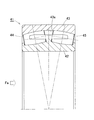
- the present invention relates to an application in which an uneven load is applied to two rows of rollers arranged in the bearing width direction, for example, a double row spherical roller bearing used for supporting a main shaft of a wind power generator or an industrial machine.
- an axial load caused by wind force acts on the bearing that supports the main shaft of the wind power generator.
- the main shaft supporting bearing is a double-row self-aligning roller bearing 41 having a symmetrical structure in the axial direction as shown in FIG. 20, two rows of rollers 44, 45 interposed between the inner ring 42 and the outer ring 43 are arranged. Of these, only the roller 45 in one row, which is mainly on the rear side with respect to the axial load Fa, receives the axial load Fa. That is, one row of rollers 45 receives both a radial load and an axial load, while the other row of rollers 44 receives only a radial load.
- the roller 45 in the row receiving the radial load and the axial load has a larger contact surface pressure than the roller 44 in the row receiving only the radial load, and the rolling surface of the roller 45 and the surface of the raceway surface 43a of the outer ring 43 are increased. Damage and wear are likely to occur.
- the rolling life of the rollers 45 in one row is shorter than the rolling life of the rollers 44 in the other row, and the actual life of the entire bearing is determined by the short rolling life of the rows of rollers 45 that receive this axial load.
- the lengths of the two rows of rollers are made different from each other (see Patent Document 1), or the contact angles of the two rows of rollers are made different from each other. (See Patent Document 2).
- the bearing size standard ISO standard; JISB1512
- the load capacity of the roller in the row subjected to the axial load can be increased to an appropriate value only by using one of the above two methods. Is difficult. That is, since the inner diameter, outer diameter, and bearing width are determined with respect to the nominal number according to the dimensional standard, the bearing width exceeds the standard value if the length of the roller in the row receiving the axial load is too long. Moreover, if the contact angle of the row roller receiving the axial load is too large, the inner diameter exceeds the standard value.
- Patent Document 3 makes it possible to equalize the contact surface pressure received by both rows with respect to a fatigue load that is applied on a daily basis, thereby improving the actual life of the entire bearing.
- extreme loads which are the maximum loads that are expected to occur in 50 years
- the load capacity is insufficient in the row with the short roller length only by setting the above parameters. There is.
- the purpose of the present invention is as a bearing suitable for applications in which axial loads and radial loads are applied, and loads having different sizes act on two rows of rollers arranged in the axial direction.
- Another object of the present invention is to provide a double row self-aligning roller bearing capable of appropriately sharing the load even with extreme load.
- the double row spherical roller bearing according to the present invention is: Inner ring, An outer ring having a spherical raceway surface; Two rows of rollers arranged in the bearing width direction, interposed between the inner ring and the outer ring, Each of the two rows of rollers is a double row self-aligning roller bearing having an outer peripheral surface having a cross-sectional shape along the raceway surface of the outer ring,
- the ratio of the contact angle ⁇ 1 of one row of rollers to the contact angle ⁇ 2 of the other row of rollers is in the range of 0.25 ⁇ ⁇ 1 / ⁇ 2 ⁇ 0.5
- the ratio with B2 is in the range of 0.5 ⁇ B1 / B2 ⁇ 0.6.
- the other row of rollers can bear a large axial load.
- a roller with a large contact angle bears almost all of the axial load and a part of the radial load, and a roller with a small contact angle.
- the contact surface pressure of the rollers in both rows can be made uniform. As a result, a large load capacity can be ensured in the entire bearing, and the substantial life of the entire bearing can be improved.
- each double row spherical roller bearing is assumed to be used as a spindle support bearing for a wind turbine generator.
- the assumed load condition refers to an axial load and a radial load, which are fatigue loads, when an average wind power generator is operating most normally in consideration of various conditions such as power generation capacity and installation location. .
- the optimal contact angle ratio may not be 1: 3.
- the optimum contact angle ratio falls within the range of 1: 2 to 1: 4. That is, by setting the ratio of the contact angles of both rows to a range of 0.25 ⁇ ⁇ 1 / ⁇ 2 ⁇ 0.5, it is possible to appropriately share the load between the two rows of rollers with respect to the fatigue load.
- the ratio of the bearing width direction distance B2 from the end surface to the intersection is in the range of 0.5 ⁇ B1 / B2 ⁇ 0.6, so that the length of the roller in the one row that bears almost only the radial load. However, it does not become excessively short within the range of the standard dimension. Therefore, it is avoided that the load capacity of the one row of rollers is insufficient even for an extreme load that needs to be assumed to be loaded from various directions. Therefore, it is possible to appropriately share the load between the two rows of rollers for both the fatigue load and the extreme load within the limits of the dimensional standard.
- the ratio between the roller length L1 of the one row and the roller length L2 of the other row may be in the range of 0.9 ⁇ L1 / L2 ⁇ 1.0. According to this configuration, since the roller length of the row with a large contact angle is equal to or longer than the roller length of the row with a small contact angle, the load capacity with respect to the axial load of the roller with the large contact angle is reliably improved. At the same time, by setting the roller length of the row with a small contact angle to 90% or more of the roller length of the other row, as described above, the length of the roller of the one row bearing almost only the radial load. Is prevented from becoming excessively short within the range of the standard dimensions.
- an inclination angle ⁇ 2 of the cage that holds the rollers of the other row is a roller maximum diameter angle ⁇ 2 that is an inclination angle of a position that forms the maximum diameter of the rollers of the other row.
- 0 ⁇ ⁇ 2 ⁇ ⁇ 2 The relationship indicated by For example, when the pocket surface of the column portion of the cage is a cylindrical surface, the center line of the cylindrical surface is relative to the cage center line (bearing center axis). It is an angle to be formed.
- the “inclination angle ⁇ 2 of the cage” may be an inclination angle of the outer diameter surface of the cage or an inclination angle of the inner diameter surface of the cage.
- the roller in the other row that is, the roller in the rear side with respect to the input direction of the axial load has a large maximum diameter angle ⁇ 2, so the cage inclination angle ⁇ 2 is appropriately set, and the pocket surface of the cage is the maximum diameter of the roller. You may make it hold a position. At this time, 0 ⁇ ⁇ 2 ⁇ ⁇ 2 By doing so, the posture stability of the rollers is not impaired. Further, by adopting such a cage shape, it is possible to prevent the deterioration of the incorporation characteristic peculiar to the left-right row asymmetric design and to stably hold the rollers.
- each of the rollers has a DLC film having a multilayer structure on the outer peripheral surface,
- the film thickness of this DLC film is 2.0 ⁇ m or more,
- the film hardness of each layer in the multilayer DLC film may be such that the layer on the outer layer side increases stepwise.
- the DLC is an abbreviation for Diamond-like Carbon.
- ⁇ Abrasion resistance is improved by DLC film treatment on the outer peripheral surface of the roller.
- the DLC film employs a multilayer structure with excellent adhesion to the base material, and the film thickness is desirably 2.0 ⁇ m or more. Further, by setting the roughness value of the outer peripheral surface on which the DLC film is applied to 0.3 Ra or less as the arithmetic average roughness Ra and 0.05 or less as the root mean square slope R ⁇ q, the aggression against the counterpart material can be alleviated. Furthermore, the film hardness of the DLC film can obtain high adhesion by increasing the hardness stepwise in a multilayer structure.
- This double row spherical roller bearing is suitable for supporting the main shaft of a wind power generator.
- a radial load due to the weight of the blade and the rotor head and an axial load due to wind force are applied to the double row spherical roller bearing that supports the main shaft of the wind power generator.
- both the roller radial load and the axial load of the other row are subjected, and the roller of the one row substantially receives only the radial load.
- the roller of the row receiving the axial load is the roller of the other row having a large contact angle
- the roller of the row receiving only the radial load is the roller of the one row having a small contact angle.
- Both the fatigue load and the extreme value load are appropriately shared by the rollers in both rows.
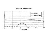
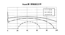
- FIG. 4 shows the distribution analysis results of the contact pressure of the roller on the front side when a composite load of axial load and radial load is applied to multiple types of double row spherical roller bearings with different contact angle ratios for both rows of rollers. It is a graph.
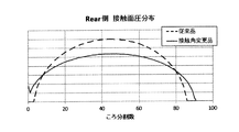
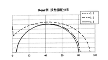
- Fig. 5 shows the distribution analysis results of the contact pressure of the roller on the rear side when a composite load of axial load and radial load is applied to multiple types of double row spherical roller bearings with different contact angle ratios for both rows of rollers. It is a graph. It is the figure which illustrated the ratio of the roller length with respect to a bearing width on the same drawing about several conventional double row self-aligning roller bearings.
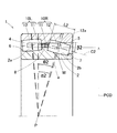
- a double-row self-aligning roller bearing (hereinafter sometimes simply referred to as “bearing”) 1 will be described with reference to FIG.
- this double-row self-aligning roller bearing 1
- left and right rows of rollers 4 and 5 arranged in the bearing width direction (axial direction) are interposed between an inner ring 2 and an outer ring 3.
- the raceway surface 3 a of the outer ring 3 has a spherical shape, and the rollers 4 and 5 in each of the left and right rows have a cross-sectional shape along the raceway surface 3 a of the outer ring 3.
- the outer peripheral surfaces of the rollers 4 and 5 are rotating curved surfaces obtained by rotating an arc along the raceway surface 3a of the outer ring 3 around the center lines C1 and C2.
- the inner ring 2 is formed with double-row raceway surfaces 2a and 2b having a cross-sectional shape along the outer peripheral surfaces of the rollers 4 and 5 in the left and right rows.
- collars (small collars) 6 and 7 are provided, respectively.
- An intermediate collar 8 is provided at the center of the outer peripheral surface of the inner ring 2, that is, between the left row roller 4 and the right row roller 5.
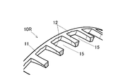
- the rollers 4 and 5 in the left and right rows are held by the cages 10L and 10R, respectively.
- a plurality of column portions 12 extend to the left side from the annular portion 11, and the left row rollers 4 are held in pockets between these column portions 12.
- the right row retainer 10 ⁇ / b> R a plurality of column portions 12 extend to the right side from the annular portion 11, and the right row rollers 5 are held in pockets between the column portions 12.
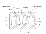
- the rollers 4 and 5 in each of the left and right rows are asymmetric rollers in which the positions of the maximum diameters D1max and D2max deviate from the center A1 and A2 of the roller length.
- the position of the maximum diameter D1max of the roller 4 in the left row is on the right side of the center A1 of the roller length
- the position of the maximum diameter D2max of the roller 5 in the right row is on the left side of the center A2 of the roller length.
- Induced thrust loads are generated in the rollers 4 and 5 in the left and right rows of such asymmetric rollers.
- the middle collar 8 of the inner ring 2 is provided.
- the combination of the asymmetrical rollers 4 and 5 and the middle collar 8 guides the rollers 4 and 5 at the three locations of the inner ring 2, the outer ring 3 and the middle collar 8, so that the guidance accuracy is good.
- the contact angles of the rollers 4 and 5 in both rows are both greater than 0 ° and different from each other.
- the contact angle ⁇ 2 of the rollers 5 in the right row is larger than the contact angle ⁇ 1 of the rollers 4 in the left row.
- the ratio of the contact angle ⁇ 1 of the left row roller 4 to the contact angle ⁇ 2 of the right row roller 5 is set within a range of 1: 2 to 1: 4, that is, 0.25 ⁇ ⁇ 1 / ⁇ 2 ⁇ 0.5. Yes.
- the left row roller 4 and the right row roller 5 have the same maximum diameters D1max and D2max, and have different lengths L1 and L2 along the center lines C1 and C2.
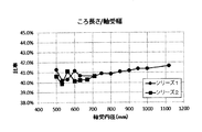
- the length L2 of the long roller 5 is preferably 39% or more of the bearing width (bearing width direction distance from the bearing end surface E1 on the left row side to the bearing end surface E2 on the right row side) B.
- the length L1 of the left row roller 4 and the length L2 of the right row roller 5 may be equal.
- the length L2 of the roller having the large contact angle is set longer than the length L1 of the roller having the small contact angle, so that the load on the axial load of the roller having the large contact angle is increased. The capacity is further improved.
- the position in the bearing width direction of the intersection P of the two action lines S1 and S2 forming the contact angles ⁇ 1 and ⁇ 2 of both rows is closer to the roller 4 side where the contact angle is smaller than the center position Q in the bearing width direction of the middle collar 8. Is shifted by a distance K. Thereby, the contact angle ⁇ 2 of the long roller 5 can be increased without making the long roller 5 longer than necessary.
- the action lines S1 and S2 are lines on which a combined force of forces acting on the contact portions between the rollers 4 and 5 and the inner ring 2 and the outer ring 3 acts. A point P where the action lines S1 and S2 intersect with each other is located on the bearing center axis O.
- the bearing width direction position of the intersection point P includes the bearing width direction distance B1 from the bearing end surface E1 on the left column side where the contact angle is small to the intersection point P, and the bearing end surface E2 on the right column side where the contact angle is large. Is set such that the ratio with the distance B2 in the bearing width direction from the point P to the intersection point P is in the range of 0.5 ⁇ B1 / B2 ⁇ 0.6.
- the bearing 1 having this configuration is used in applications in which axial loads and radial loads are applied and loads having different sizes act on the left and right roller rows, for example, as a main shaft support bearing of a wind turbine generator.
- the roller 4 in the left row is located on the side closer to the swirl blade (front side: left side in FIG. 1), and the roller 5 in the right row is located on the far side (rear side: right side in FIG. 1).
- the bearing 1 is installed.
- the axial load Fa from the main shaft is applied in a direction from the front side toward the rear side.
- roller 5 in the right row having a large contact angle ⁇ 2 bears almost all of the axial load and a part of the radial load
- roller 4 in the left row having a small contact angle ⁇ 1 bears the rest of the radial load.
- the length L1 of the roller in the left row that bears almost only the radial load is It will not be too short within the dimensions. If the length of one row of rollers is too short, the load capacity of the rollers will be insufficient, and if an extremely large load such as an extreme load is applied in the radial direction, edge stress will occur at both ends of the rollers. This will cause a decrease in the service life. However, in the bearing 1 according to the present embodiment, it is avoided that the load capacity of the rollers in one row is insufficient even for an extreme load that needs to be assumed to be loaded from various directions. Therefore, according to the bearing 1, it is possible to appropriately share the load between the two rows of rollers for both the fatigue load and the extreme load within the limits of the dimensional standard.
- the roller length L2 of the other row is longer than the roller length L1 of one row (in this example, the left row). More preferably, the ratio between L1 and L2 is in the range of 0.9 ⁇ L1 / L2 ⁇ 1.0 so that the length L1 does not become excessively short.
- the conventional product shown in FIG. 10 has a small contact surface pressure on the front side and a large contact surface pressure on the rear side, and the load load is not uniform between the front side and the rear side.
- the contact surface pressure is generated on the entire roller on the front side, so that the maximum value of the contact surface pressure on the rear side is lowered and the contact surface pressure difference between both rows is small. Are equalized.
- FIG. 5 shows the contact surface pressure analysis result distribution of the rollers 4 in the front side, that is, the left row
- FIG. 6 shows the contact surface pressure analysis result distribution of the rollers 5 in the rear side, that is, the right row.
- a contact angle ratio of 1: 1 is a conventional product
- contact angle ratios of 1: 2 and 1: 3 are contact angle change products of the present invention.
- the contact surface pressure ratio is 1: 3, and the contact surface pressure is most even on the front side and the rear side.
- the contact angle ratio of 1: 2 is not equalized compared to the contact angle ratio of 1: 3, but it is sufficiently equalized compared to the contact angle ratio of 1: 1.
- the contact angle ratio is desirably 1: 2 or more and 1: 4 or less.
- the assumed axial load and radial load are the axial load, which is the fatigue load when the average wind power generator is operating most normally in consideration of various conditions such as power generation capacity and installation location, and the like. Refers to radial load. Therefore, in a double row self-aligning roller bearing used in a wind power generator having different conditions as compared with an average wind power generator, the optimal contact angle ratio may not be 1: 3. However, even in that case, the optimum contact angle ratio falls within the range of 1: 2 to 1: 4.
- the ratio of the contact angles of the rollers in both rows within the range of the dimensional standard is added by adding a condition that the length L2 of the roller 5 having a long length is 39% or more of the bearing width B.
- a double row self-aligning roller bearing in which the above is appropriate is obtained.
- the ratio of the length L2 of the roller 5 to the bearing width B was investigated. As a result, as shown in FIG. 7, the ratio was found to be 39% or more.
- the dimensional standard is a standard that defines an inner diameter, an outer diameter, and a bearing width.
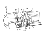
- a casing 23a of the nacelle 23 is installed on the support base 21 via a swivel bearing 22 (FIG. 9) so as to be horizontally swivelable.
- a main shaft 26 is rotatably installed via a main shaft support bearing 25 installed in the bearing housing 24, and a blade 27 serving as a swirl wing is formed at a portion protruding from the casing 23 a of the main shaft 26. Is attached.
- the other end of the main shaft 26 is connected to the speed increaser 28, and the output shaft of the speed increaser 28 is coupled to the rotor shaft of the generator 29.
- the nacelle 23 is turned at an arbitrary angle by the turning motor 30 via the speed reducer 31.
- two main shaft support bearings 25 are arranged side by side, but may be one.
- the inclination angle ⁇ 2 of the cage 10R that holds the roller 5 in the other row is an inclination angle at a position where the maximum diameter of the roller 5 in the other row is formed.
- the “inclination angle ⁇ 2 of the cage 10R” is, for example, when the pocket surface 12a of the column portion 12 of the cage 10R is a cylindrical surface, the center line C2 of the cylindrical surface is the center of the cage (bearing center axis).
- the angle formed with respect to O) is the cage inclination angle ⁇ 2.
- the “cage inclination angle ⁇ 2” may be an inclination angle of the outer diameter surface of the cage 10R or an inclination angle of the inner diameter surface of the cage 10R.
- the roller 5 in the other row that is, the roller 5 in the rear side with respect to the input direction of the axial load has a larger maximum diameter angle ⁇ 2, so the cage inclination angle ⁇ 2 is set, and the pocket surface 12a of the cage 10R is a roller.
- a maximum diameter position of 5 may be held. At this time, 0 ⁇ ⁇ 2 ⁇ ⁇ 2
- the posture stability of the roller 5 is not impaired.
- retainer 10R by setting it as the shape of such a holder
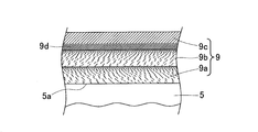
- the rollers 4 and 5 in each row have a DLC film 9 having a multilayer structure (three or more layers) on the outer peripheral surface.
- the DLC film 9 may be applied to the raceway surfaces 2a, 2b, and 3a of the inner ring 2 and the outer ring 3 in the same manner as the rollers 4 and 5, but here, the DLC film 9 of the rollers 4 and 5 will be described.
- the film thickness of this DLC film 9 is 2.0 ⁇ m or more.
- the DLC film 9 is composed of the base layer 9a and the mixed layer 9b in order from the base material side of the rollers 4 and 5, as schematically shown in the cross section of the DLC film 9 of the roller 5 on the rear side in FIG. , And the surface layer 9c.
- the surface roughness of the outer surfaces of the base materials of the rollers 4 and 5 is expressed as follows: Ra ⁇ 0.3 and R ⁇ q ⁇ 0.05 with arithmetic roughness Ra and root mean square slope R ⁇ q. It is.
- the film hardness of each of the layers 9a, 9b, 9c in the multilayered DLC film 9 increases stepwise on the outer layer side.
- the DLC film 9 employs a multilayer structure that is excellent in adhesion to the base material.
- the film thickness is desirably 2.0 ⁇ m or more.
- the roughness value of the outer peripheral surface to which the DLC film 9 is applied can be set to 0.3 Ra or less as the arithmetic average roughness Ra and 0.05 or less as the root mean square slope R ⁇ q, the aggression against the counterpart material can be alleviated.
- the film hardness of the DLC film 9 can obtain high adhesion by increasing the hardness stepwise in a multilayer structure.
- the material of the rollers 4 and 5 and the DLC film 9 will be specifically described.
- the rollers 4, 5, the inner ring 2, and the outer ring 3 are made of an iron-based material.
- any steel material generally used as a bearing member can be used, and examples thereof include high carbon chromium bearing steel, carbon steel, tool steel, martensitic stainless steel, and the like.
- the surface on which the DLC film 9 is formed preferably has a Vickers hardness of Hv650 or higher. By setting it as Hv650 or more, a hardness difference with the DLC film 9 (underlayer) can be reduced, and adhesiveness can be improved.
- a nitrided layer is formed by nitriding before forming the film.
- the nitriding treatment it is preferable to perform a plasma nitriding treatment in which an oxide layer that hinders adhesion is hardly generated on the surface of the base material.
- the hardness of the surface after nitriding is Hv1000 or more in terms of Vickers hardness in order to further improve the adhesion to the DLC film 9 (underlayer).
- the surface of the rollers 4 and 5 on which the DLC film 9 is formed that is, the surface on which the base layer 9a is formed, has an arithmetic average roughness Ra of 0.1 to 0.3 ⁇ m and a square Average square root slope R ⁇ q is 0.05 or less.
- R ⁇ q is preferably 0.03 or less, more preferably 0.02 or less.
- the arithmetic average roughness Ra and the root mean square slope R ⁇ q are numerical values calculated in accordance with JISB0601, and are measured using a contact-type or non-contact-type surface roughness meter. Specific measurement conditions are a measurement length of 4 mm and a cutoff of 0.8 mm.
- the root mean square slope R ⁇ q on the surface of the base material By setting the root mean square slope R ⁇ q on the surface of the base material to 0.05 or less, the peak in the roughness curve becomes gentle, the radius of curvature of the protrusion increases, and the local surface pressure can be reduced. Further, at the time of film formation, electric field concentration at a micro level due to roughness can be suppressed, local changes in film thickness and hardness can be prevented, and as a result, peeling resistance of the hard film can be improved.
- the maximum peak height Rp obtained from the roughness curve of the base material surface is preferably 0.4 ⁇ m or less.
- the maximum peak height Rp is calculated in accordance with JISB0601.
- the relationship between the maximum peak height Rp obtained from the roughness curve and the arithmetic average roughness Ra is preferably 1 ⁇ Rp / Ra ⁇ 2, and more preferably 1.2 ⁇ Rp / Ra ⁇ 2.
- the skewness Rsk obtained from the roughness curve of the base material surface is preferably negative.
- Rsk is an index of the degree of distortion, and is more preferably ⁇ 0.2 or less.
- the skewness Rsk is an index that quantitatively represents the vertical symmetry of the amplitude distribution curve around the average line, that is, an index indicating the deviation of the surface roughness from the average line.
- the skewness Rsk is calculated in accordance with JISB0601. When the skewness Rsk is negative, it means that the roughness shape is convex downward (valley), and there are many flat portions on the surface. As a result, it can be said that the surface has few convex portions and hardly causes stress concentration due to the protruding portions.
- FIG. 11 is a schematic cross-sectional view showing the structure of the DLC film 9.
- the DLC film 9 includes (1) an underlayer 9a mainly composed of Cr and WC directly formed on the surfaces of the rollers 4 and 5, and (2) on the underlayer 9a. It has a three-layer structure including a mixed layer 9b mainly composed of WC and DLC and (3) a surface layer 9c mainly composed of DLC formed on the mixed layer 9b.
- the content of WC in the mixed layer decreases continuously or stepwise from the base layer 9a side to the surface layer 9c side, and the DLC content in the mixed layer 9b This is a layer with a higher rate.
- the film structure of the DLC film 9 is a three-layer structure as described above, so that sudden changes in physical properties (hardness, elastic modulus, etc.) are avoided.
- the underlayer 9a contains Cr, it has a good compatibility with a base material made of a cemented carbide material or an iron-based material, and has excellent adhesion to the base material as compared with the case where W, Ti, Si, Al, or the like is used. . Further, WC used for the underlayer 9a has intermediate hardness and elastic modulus between Cr and DLC, and residual stress concentration after film formation hardly occurs. Moreover, it is preferable that the underlayer 9a has a gradient composition in which the Cr content is small and the WC content is high from the roller surface side toward the mixed layer 9b side. Thereby, it is excellent in the adhesiveness in both surfaces of the roller surface and the mixed layer 9b.
- the mixed layer 9b is an intermediate layer interposed between the base layer and the surface layer.
- the WC used for the mixed layer 9b has intermediate hardness and elastic modulus between Cr and DLC, and residual stress concentration after film formation hardly occurs. Since the mixed layer 9b has a gradient composition in which the WC content decreases from the base layer 9a side to the surface layer 9c side and the DLC content increases, the both sides of the base layer 9a and the surface layer 9c Excellent adhesion. In addition, WC and DLC are physically coupled in the mixed layer, and damage in the mixed layer can be prevented. Furthermore, since the DLC content is increased on the surface layer 9c side, the adhesion between the surface layer 9c and the mixed layer 9b is excellent.
- the mixed layer 9b is a layer in which non-adhesive DLC is bonded to the base layer 9a side by WC by an anchor effect.
- the surface layer 9c is a film mainly composed of DLC.
- the surface layer 9c preferably has an inclined layer portion 9d whose hardness increases continuously or stepwise from the mixed layer 9b side on the side adjacent to the mixed layer 9b. This is a portion obtained by changing (raising) the bias voltage continuously or stepwise in order to avoid a sudden change in the bias voltage when the bias voltage is different between the mixed layer 9b and the surface layer 9c.
- the inclined layer portion 9d changes the bias voltage as described above, and as a result, the hardness is inclined as described above.
- the reason why the hardness increases continuously or stepwise is that the constituent ratio of the graphite structure (sp2) and the diamond structure (sp3) in the DLC structure is biased toward the latter as the bias voltage increases. Thereby, there is no sudden hardness difference between the mixed layer and the surface layer, and the adhesion between the mixed layer 9b and the surface layer 9c is further improved.
- the film thickness (total of the three layers) of the DLC film 9 is preferably 0.5 to 3.0 ⁇ m. If the film thickness is less than 0.5 ⁇ m, the abrasion resistance and the mechanical strength may be inferior, and if it exceeds 5.0 ⁇ m, the film tends to peel off. Furthermore, it is preferable that the ratio of the thickness of the surface layer 9c to the film thickness of the DLC film 9 is 0.8 or less. When this ratio exceeds 0.8, the gradient structure for physically bonding WC and DLC in the mixed layer 9b tends to be a discontinuous structure, and the adhesion may be deteriorated.
- the peel resistance is excellent.
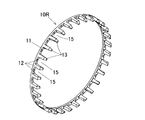
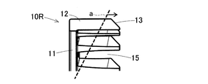
- FIG. 12 to 19 show configuration examples of the rear-side cage 10R.
- the front-side cage 10L FIG. 1
- the rear-side cage 10R with respect to the items described with reference to FIGS. Further, the configuration example of the cage 10R is applied to both the first embodiment and the embodiment of FIG.
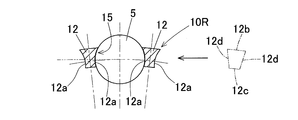
- the cylindrical pocket surface 12a is removed from the columnar portion 12 of the cage 10R from the rod-shaped portion having the same basic cross-sectional shape (the shape indicated by the imaginary line in FIG. 14) in each portion in the length direction.
- a tapered shape portion 13 is provided at the tip.
- the basic cross-sectional shape is a shape composed of an outer peripheral surface 12b and an inner peripheral surface 12c each forming a part of a cylindrical surface, and two planar side surfaces 12d extending in the radial direction.
- the diameter of the cylindrical surface forming the pocket surface 12 a is slightly larger than the maximum diameter of the rollers 5.
- the pocket surface 12a is a cylindrical surface centered on the center line C2 (FIGS. 1 and 10). As shown in FIG. 17, the center line C ⁇ b> 2 is inclined with respect to the direction in which the column portion 12 extends so that the tip end side of the column portion approaches the inner diameter side.
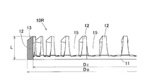
- the outer diameter Do, inner diameter Di, and column portion length L of the cage 10R shown in FIG. 13 are optimized as follows.
- the outer diameter Do of the annular portion 11 of the cage 10R is larger than the pitch circle diameter PCD of the arrangement of the rollers 5, and the inner diameter Di of the annular portion 11 is smaller than the pitch circle diameter PCD (FIG. 10).
- the outer diameter Do of the annular portion 11 is, for example, PCD ⁇ 102 to 105%.
- An inner diameter Di of the annular portion 11 is, for example, PCD ⁇ 95 to 98%.
- the length L of the column portion 12, specifically the length L of the portion constituting the pocket 7 of the column portion 12, is 65% or less of the roller length L2 (FIGS. 1 and 10).
- the tapered portion 13 (FIGS. 12 to 13 and FIGS. 15 to 17) is formed on the outer diameter surface of the tip of the column portion 12 so as to be lowered toward the inner diameter side of the cage as far as the end.
- the tapered portion 13 is on a straight line a (indicated by a broken line in FIG. 15) forming the maximum diameter angle of the roller 5, or starts from the front end side of the column portion with respect to the straight line a.
- the tapered portion 13 starts on the position M ⁇ (FIG. 10) where the maximum diameter is on the center line C ⁇ b> 2 of the roller 5, or from the front end side of the column portion with respect to this position M.
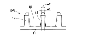
- the tapered portion 13 is formed in the column portion 12 and the cylindrical pocket surface 12a is inclined with respect to the axial direction in which the column portion 12 extends, so that the column portion 12 is formed as shown in FIG.
- the column width viewed from the outside in the cage radial direction toward the cage center side is the narrowest W1 at the forefront of the column 12 and is narrower than the width W2 before the tapered portion 13 starts. ing. Further, the radial thickness d (FIG. 17) of the tip surface 12e of the column part 12 is small.
- the bearings 10L and 10R are made of bearing steel, other iron-based materials, or brass-based materials.
- the pocket surface 12a of the column portion 12 is a cylindrical surface, so that the rollers 5 can be reliably held. Further, since the tapered portion 13 is formed, the assemblability of the rollers 5 is improved.
- the center line C2 of the cylindrical surface serving as the pocket surface 12a of the column part 12 is inclined toward the inner diameter side on the tip side with respect to the direction in which the column part 12 extends. Therefore, as in the example of FIG. 19, if the tapered portion 13 (see FIG. 18) is not provided, the column width when the column portion 12 is viewed from the outside in the cage radial direction to the cage center side is the column width.
- both the circumferential width W1 (FIG. 16) and the radial thickness d (FIG. 17) at the tip of the column portion are small. Therefore, the assemblability of the rollers 5 is improved and the weight of the cage 10R can be reduced. Since the assembling property of the roller 5 is improved, it is not necessary to greatly deform the cage 10R at the time of assembling, and the deformation of the shape due to the deformation of the cage 10R is prevented.
- the tapered portion 13 is formed so as to eliminate a useless portion, it is preferable to form the tapered portion 13 from the viewpoint of reducing the weight without affecting the retainability of the rollers 5.
- the taper-shaped portion 13 starts on the position M (FIG. 16) where the maximum diameter of the roller 5 is reached, or from the front end side of the column portion. Therefore, the retainability of the rollers 5 is ensured.
- the radial thickness d (FIG. 17) of the tip of the tapered portion 13 is thin.
- the pocket surface 12a formed of a cylindrical surface can be drilled from the tip side of the column portion 12. In order to form, it is necessary to leave a flat surface at the tip, and it is preferable to reduce the thickness within a range that does not hinder processing.
- the rear side cage 10R has been described, but the configuration and effect of the above cage shape are the same as that of the rear side cage 10R.
- These retainers 10L and 10R may have a shape that does not have the tapered portion 13 at the end of the column portion 12, as in the example of FIG. 19, for example, and the center line C2 of the cylindrical surface forming the pocket surface 12a is The shape which is not inclined with respect to the direction where the pillar part 12 extends may be sufficient.
Landscapes
- Engineering & Computer Science (AREA)
- General Engineering & Computer Science (AREA)
- Mechanical Engineering (AREA)
- Life Sciences & Earth Sciences (AREA)
- Sustainable Development (AREA)
- Sustainable Energy (AREA)
- Chemical & Material Sciences (AREA)
- Combustion & Propulsion (AREA)
- Rolling Contact Bearings (AREA)
- Support Of The Bearing (AREA)
Priority Applications (4)
| Application Number | Priority Date | Filing Date | Title |
|---|---|---|---|
| DK19788217.8T DK3783237T3 (da) | 2018-04-20 | 2019-04-17 | Dobbeltrækket, selvjusterende rulleleje |
| EP19788217.8A EP3783237B1 (en) | 2018-04-20 | 2019-04-17 | Double-row self-aligning roller bearing |
| CN201980026335.1A CN111989500B (zh) | 2018-04-20 | 2019-04-17 | 多排自动调心滚子轴承 |
| US17/071,368 US11306776B2 (en) | 2018-04-20 | 2020-10-15 | Double-row self-aligning roller bearing |
Applications Claiming Priority (4)
| Application Number | Priority Date | Filing Date | Title |
|---|---|---|---|
| JP2018081203 | 2018-04-20 | ||
| JP2018-081203 | 2018-04-20 | ||
| JP2019-072707 | 2019-04-05 | ||
| JP2019072707A JP7488633B2 (ja) | 2018-04-20 | 2019-04-05 | 複列自動調心ころ軸受 |
Related Child Applications (1)
| Application Number | Title | Priority Date | Filing Date |
|---|---|---|---|
| US17/071,368 Continuation US11306776B2 (en) | 2018-04-20 | 2020-10-15 | Double-row self-aligning roller bearing |
Publications (1)
| Publication Number | Publication Date |
|---|---|
| WO2019203265A1 true WO2019203265A1 (ja) | 2019-10-24 |
Family
ID=68239674
Family Applications (1)
| Application Number | Title | Priority Date | Filing Date |
|---|---|---|---|
| PCT/JP2019/016453 Ceased WO2019203265A1 (ja) | 2018-04-20 | 2019-04-17 | 複列自動調心ころ軸受 |
Country Status (5)
| Country | Link |
|---|---|
| US (1) | US11306776B2 (enExample) |
| JP (1) | JP7663732B2 (enExample) |
| CN (1) | CN111989500B (enExample) |
| DK (1) | DK3783237T3 (enExample) |
| WO (1) | WO2019203265A1 (enExample) |
Cited By (1)
| Publication number | Priority date | Publication date | Assignee | Title |
|---|---|---|---|---|
| US20220196070A1 (en) * | 2020-12-17 | 2022-06-23 | Aktiebolaget Skf | Bearing component and method of manufacturing thereof |
Families Citing this family (5)
| Publication number | Priority date | Publication date | Assignee | Title |
|---|---|---|---|---|
| CN112739907B (zh) * | 2018-09-24 | 2023-06-20 | 维斯塔斯风力系统有限公司 | 风力涡轮机机舱结构和组装风力涡轮机机舱结构的方法 |
| WO2022202630A1 (ja) * | 2021-03-22 | 2022-09-29 | Ntn株式会社 | ころ軸受 |
| CN115853907B (zh) * | 2022-12-27 | 2025-06-13 | 洛阳轴承集团股份有限公司 | 一种风机用非对称调心滚子轴承及其设计方法 |
| CN116480685A (zh) * | 2023-03-13 | 2023-07-25 | 山东哈临集团有限公司 | 一种船舶推进器用调心滚子轴承 |
| CN119731431A (zh) * | 2023-07-26 | 2025-03-28 | 铁姆肯公司 | 用于风力涡轮主轴的轴承布置 |
Citations (8)
| Publication number | Priority date | Publication date | Assignee | Title |
|---|---|---|---|---|
| WO2005050038A1 (ja) | 2003-11-18 | 2005-06-02 | Ntn Corporation | 複列自動調心ころ軸受および風力発電機主軸支持装置 |
| JP2010112527A (ja) * | 2008-11-10 | 2010-05-20 | Ntn Corp | ロッカアームアッシー |
| JP2012219995A (ja) * | 2011-04-14 | 2012-11-12 | Ntn Corp | 転がり軸受およびその製造方法 |
| US20140112607A1 (en) | 2012-10-18 | 2014-04-24 | Schaeffler Technologies AG & Co. KG | Roller bearing for wind turbines |
| JP2015205328A (ja) * | 2014-04-22 | 2015-11-19 | 株式会社神戸製鋼所 | Znめっき鋼板の熱間成形用金型 |
| JP2016186355A (ja) * | 2015-03-27 | 2016-10-27 | Ntn株式会社 | 転がり軸受用保持器および転がり軸受 |
| WO2017164325A1 (ja) * | 2016-03-24 | 2017-09-28 | Ntn株式会社 | 複列自動調心ころ軸受 |
| JP2017180831A (ja) | 2016-03-24 | 2017-10-05 | Ntn株式会社 | 複列自動調心ころ軸受 |
Family Cites Families (20)
| Publication number | Priority date | Publication date | Assignee | Title |
|---|---|---|---|---|
| US3912346A (en) * | 1969-02-06 | 1975-10-14 | Poznanska Fabryka Lozysk Toczn | Double-row self-aligning bearing |
| US4828404A (en) * | 1988-05-16 | 1989-05-09 | Nippon Seiko Kabushiki Kaisha | Self-aligning roller bearing |
| GB9623126D0 (en) * | 1996-11-06 | 1997-01-08 | Timken Co | Bearing assembly |
| JP2004028139A (ja) * | 2002-06-21 | 2004-01-29 | Nsk Ltd | 調心輪付き複列円すいころ軸受 |
| JP2004092687A (ja) * | 2002-08-29 | 2004-03-25 | Nsk Ltd | 複列アンギュラ玉軸受 |
| US7922396B2 (en) * | 2004-09-21 | 2011-04-12 | Ntn Corporation | Double row self-aligning roller bearing and main shaft support structure of wind power generator |
| BE1017166A3 (enExample) * | 2006-06-13 | 2008-03-04 | Hansen Transmissions Int | |
| JP2008202732A (ja) * | 2007-02-21 | 2008-09-04 | Ntn Corp | 密封型複列アンギュラ玉軸受および電磁クラッチ |
| JP5620860B2 (ja) * | 2010-03-30 | 2014-11-05 | Ntn株式会社 | 転がり軸受 |
| JP5664484B2 (ja) | 2011-07-15 | 2015-02-04 | ブラザー工業株式会社 | レイアウト編集装置およびレイアウト編集プログラム |
| DE102011086925A1 (de) * | 2011-11-23 | 2013-05-23 | Schaeffler Technologies AG & Co. KG | Zweireihiges Pendelrollenlager |
| JP2014059025A (ja) | 2012-09-19 | 2014-04-03 | Ntn Corp | 風力・潮力発電用軸受 |
| CN107575469B (zh) * | 2012-12-25 | 2020-12-18 | 日本精工株式会社 | 圆锥滚子轴承 |
| US20150323008A1 (en) * | 2012-12-25 | 2015-11-12 | Nsk Ltd. | Tapered roller bearing |
| DE102015204970A1 (de) | 2015-03-19 | 2016-09-22 | Schaeffler Technologies AG & Co. KG | Wälzlager, beispielsweise einer Windkraftanlage |
| US9863471B2 (en) * | 2015-04-09 | 2018-01-09 | Aktiebolaget Skf | Bearing and bearing arrangement |
| JP2017150507A (ja) * | 2016-02-22 | 2017-08-31 | 日本精工株式会社 | 4列円すいころ軸受 |
| CN108884867B (zh) | 2016-03-24 | 2020-12-18 | Ntn株式会社 | 双排自调心滚子轴承 |
| EP3273077B1 (de) | 2016-07-21 | 2020-06-03 | Aktiebolaget SKF | Wälzlager mit montageflansch |
| JP6912966B2 (ja) * | 2017-01-13 | 2021-08-04 | Ntn株式会社 | 複列自動調心ころ軸受 |
-
2019
- 2019-04-17 DK DK19788217.8T patent/DK3783237T3/da active
- 2019-04-17 WO PCT/JP2019/016453 patent/WO2019203265A1/ja not_active Ceased
- 2019-04-17 CN CN201980026335.1A patent/CN111989500B/zh active Active
-
2020
- 2020-10-15 US US17/071,368 patent/US11306776B2/en active Active
-
2024
- 2024-02-07 JP JP2024017030A patent/JP7663732B2/ja active Active
Patent Citations (8)
| Publication number | Priority date | Publication date | Assignee | Title |
|---|---|---|---|---|
| WO2005050038A1 (ja) | 2003-11-18 | 2005-06-02 | Ntn Corporation | 複列自動調心ころ軸受および風力発電機主軸支持装置 |
| JP2010112527A (ja) * | 2008-11-10 | 2010-05-20 | Ntn Corp | ロッカアームアッシー |
| JP2012219995A (ja) * | 2011-04-14 | 2012-11-12 | Ntn Corp | 転がり軸受およびその製造方法 |
| US20140112607A1 (en) | 2012-10-18 | 2014-04-24 | Schaeffler Technologies AG & Co. KG | Roller bearing for wind turbines |
| JP2015205328A (ja) * | 2014-04-22 | 2015-11-19 | 株式会社神戸製鋼所 | Znめっき鋼板の熱間成形用金型 |
| JP2016186355A (ja) * | 2015-03-27 | 2016-10-27 | Ntn株式会社 | 転がり軸受用保持器および転がり軸受 |
| WO2017164325A1 (ja) * | 2016-03-24 | 2017-09-28 | Ntn株式会社 | 複列自動調心ころ軸受 |
| JP2017180831A (ja) | 2016-03-24 | 2017-10-05 | Ntn株式会社 | 複列自動調心ころ軸受 |
Cited By (2)
| Publication number | Priority date | Publication date | Assignee | Title |
|---|---|---|---|---|
| US20220196070A1 (en) * | 2020-12-17 | 2022-06-23 | Aktiebolaget Skf | Bearing component and method of manufacturing thereof |
| US12123464B2 (en) * | 2020-12-17 | 2024-10-22 | Aktiebolaget Skf | Bearing component and method of manufacturing thereof |
Also Published As
| Publication number | Publication date |
|---|---|
| US11306776B2 (en) | 2022-04-19 |
| JP7663732B2 (ja) | 2025-04-16 |
| CN111989500A (zh) | 2020-11-24 |
| CN111989500B (zh) | 2022-04-12 |
| JP2024040292A (ja) | 2024-03-25 |
| US20210025448A1 (en) | 2021-01-28 |
| DK3783237T3 (da) | 2024-01-08 |
Similar Documents
| Publication | Publication Date | Title |
|---|---|---|
| JP7663732B2 (ja) | 複列自動調心ころ軸受 | |
| CN108884867B (zh) | 双排自调心滚子轴承 | |
| US9206847B2 (en) | Roller bearing assemblies, apparatuses, and related methods of manufacture | |
| US10697492B2 (en) | Double-row self-aligning roller bearing | |
| US20220373022A1 (en) | Rolling Bearing | |
| WO2017164325A1 (ja) | 複列自動調心ころ軸受 | |
| US11773901B2 (en) | Self-aligning roller bearing | |
| JP2019190658A (ja) | 複列自動調心ころ軸受 | |
| JP6873754B2 (ja) | 複列自動調心ころ軸受 | |
| JP2017180832A (ja) | 複列自動調心ころ軸受 | |
| CN110945256B (zh) | 双排自动调心滚柱轴承 | |
| US10197094B2 (en) | Double-row spherical roller bearing | |
| JP2010025183A (ja) | 自動調心ころ軸受 | |
| JP2005155838A (ja) | ころ軸受 | |
| JP2021008940A (ja) | クロスローラ軸受 |
Legal Events
| Date | Code | Title | Description |
|---|---|---|---|
| 121 | Ep: the epo has been informed by wipo that ep was designated in this application |
Ref document number: 19788217 Country of ref document: EP Kind code of ref document: A1 |
|
| NENP | Non-entry into the national phase |
Ref country code: DE |
|
| WWE | Wipo information: entry into national phase |
Ref document number: 2019788217 Country of ref document: EP |