EP3783237B1 - Double-row self-aligning roller bearing - Google Patents
Double-row self-aligning roller bearing Download PDFInfo
- Publication number
- EP3783237B1 EP3783237B1 EP19788217.8A EP19788217A EP3783237B1 EP 3783237 B1 EP3783237 B1 EP 3783237B1 EP 19788217 A EP19788217 A EP 19788217A EP 3783237 B1 EP3783237 B1 EP 3783237B1
- Authority
- EP
- European Patent Office
- Prior art keywords
- rollers
- rows
- bearing
- row
- double
- Prior art date
- Legal status (The legal status is an assumption and is not a legal conclusion. Google has not performed a legal analysis and makes no representation as to the accuracy of the status listed.)
- Active
Links
- 239000011248 coating agent Substances 0.000 claims description 40
- 238000000576 coating method Methods 0.000 claims description 40
- 239000000463 material Substances 0.000 claims description 30
- 230000002093 peripheral effect Effects 0.000 claims description 17
- 230000001965 increasing effect Effects 0.000 claims description 12
- 230000009471 action Effects 0.000 claims description 8
- 230000003746 surface roughness Effects 0.000 claims description 7
- 239000010410 layer Substances 0.000 description 51
- 239000002344 surface layer Substances 0.000 description 16
- 238000009826 distribution Methods 0.000 description 10
- 230000002829 reductive effect Effects 0.000 description 7
- 238000005096 rolling process Methods 0.000 description 6
- 239000011651 chromium Substances 0.000 description 5
- 230000036961 partial effect Effects 0.000 description 5
- 230000000717 retained effect Effects 0.000 description 5
- CWYNVVGOOAEACU-UHFFFAOYSA-N Fe2+ Chemical compound [Fe+2] CWYNVVGOOAEACU-UHFFFAOYSA-N 0.000 description 4
- 230000015572 biosynthetic process Effects 0.000 description 4
- 230000008859 change Effects 0.000 description 4
- 238000000034 method Methods 0.000 description 4
- 239000000203 mixture Substances 0.000 description 4
- 238000005121 nitriding Methods 0.000 description 4
- 229910000831 Steel Inorganic materials 0.000 description 3
- 230000003466 anti-cipated effect Effects 0.000 description 3
- 230000009467 reduction Effects 0.000 description 3
- 239000010959 steel Substances 0.000 description 3
- OKTJSMMVPCPJKN-UHFFFAOYSA-N Carbon Chemical compound [C] OKTJSMMVPCPJKN-UHFFFAOYSA-N 0.000 description 2
- 230000003247 decreasing effect Effects 0.000 description 2
- 238000013461 design Methods 0.000 description 2
- 230000000694 effects Effects 0.000 description 2
- 238000009434 installation Methods 0.000 description 2
- 230000000670 limiting effect Effects 0.000 description 2
- 238000005259 measurement Methods 0.000 description 2
- 238000010248 power generation Methods 0.000 description 2
- 238000012545 processing Methods 0.000 description 2
- 229910001369 Brass Inorganic materials 0.000 description 1
- 229910000975 Carbon steel Inorganic materials 0.000 description 1
- 229910001315 Tool steel Inorganic materials 0.000 description 1
- 239000000853 adhesive Substances 0.000 description 1
- 230000001070 adhesive effect Effects 0.000 description 1
- 239000010951 brass Substances 0.000 description 1
- 229910052799 carbon Inorganic materials 0.000 description 1
- 239000010962 carbon steel Substances 0.000 description 1
- 238000005520 cutting process Methods 0.000 description 1
- 230000007423 decrease Effects 0.000 description 1
- 230000006866 deterioration Effects 0.000 description 1
- 229910003460 diamond Inorganic materials 0.000 description 1
- 239000010432 diamond Substances 0.000 description 1
- 238000005553 drilling Methods 0.000 description 1
- 230000005684 electric field Effects 0.000 description 1
- 230000002708 enhancing effect Effects 0.000 description 1
- 230000006872 improvement Effects 0.000 description 1
- 238000003780 insertion Methods 0.000 description 1
- 230000037431 insertion Effects 0.000 description 1
- 238000011835 investigation Methods 0.000 description 1
- 229910000734 martensite Inorganic materials 0.000 description 1
- FXNGWBDIVIGISM-UHFFFAOYSA-N methylidynechromium Chemical group [Cr]#[C] FXNGWBDIVIGISM-UHFFFAOYSA-N 0.000 description 1
- 150000004767 nitrides Chemical class 0.000 description 1
- 230000000704 physical effect Effects 0.000 description 1
- 238000005498 polishing Methods 0.000 description 1
- 239000010935 stainless steel Substances 0.000 description 1
- 229910001220 stainless steel Inorganic materials 0.000 description 1
- 239000013585 weight reducing agent Substances 0.000 description 1
Images


Classifications
-
- F—MECHANICAL ENGINEERING; LIGHTING; HEATING; WEAPONS; BLASTING
- F16—ENGINEERING ELEMENTS AND UNITS; GENERAL MEASURES FOR PRODUCING AND MAINTAINING EFFECTIVE FUNCTIONING OF MACHINES OR INSTALLATIONS; THERMAL INSULATION IN GENERAL
- F16C—SHAFTS; FLEXIBLE SHAFTS; ELEMENTS OR CRANKSHAFT MECHANISMS; ROTARY BODIES OTHER THAN GEARING ELEMENTS; BEARINGS
- F16C23/00—Bearings for exclusively rotary movement adjustable for aligning or positioning
- F16C23/06—Ball or roller bearings
- F16C23/08—Ball or roller bearings self-adjusting
- F16C23/082—Ball or roller bearings self-adjusting by means of at least one substantially spherical surface
- F16C23/086—Ball or roller bearings self-adjusting by means of at least one substantially spherical surface forming a track for rolling elements
-
- F—MECHANICAL ENGINEERING; LIGHTING; HEATING; WEAPONS; BLASTING
- F16—ENGINEERING ELEMENTS AND UNITS; GENERAL MEASURES FOR PRODUCING AND MAINTAINING EFFECTIVE FUNCTIONING OF MACHINES OR INSTALLATIONS; THERMAL INSULATION IN GENERAL
- F16C—SHAFTS; FLEXIBLE SHAFTS; ELEMENTS OR CRANKSHAFT MECHANISMS; ROTARY BODIES OTHER THAN GEARING ELEMENTS; BEARINGS
- F16C25/00—Bearings for exclusively rotary movement adjustable for wear or play
- F16C25/06—Ball or roller bearings
- F16C25/08—Ball or roller bearings self-adjusting
-
- F—MECHANICAL ENGINEERING; LIGHTING; HEATING; WEAPONS; BLASTING
- F03—MACHINES OR ENGINES FOR LIQUIDS; WIND, SPRING, OR WEIGHT MOTORS; PRODUCING MECHANICAL POWER OR A REACTIVE PROPULSIVE THRUST, NOT OTHERWISE PROVIDED FOR
- F03D—WIND MOTORS
- F03D80/00—Details, components or accessories not provided for in groups F03D1/00 - F03D17/00
- F03D80/70—Bearing or lubricating arrangements
-
- F—MECHANICAL ENGINEERING; LIGHTING; HEATING; WEAPONS; BLASTING
- F16—ENGINEERING ELEMENTS AND UNITS; GENERAL MEASURES FOR PRODUCING AND MAINTAINING EFFECTIVE FUNCTIONING OF MACHINES OR INSTALLATIONS; THERMAL INSULATION IN GENERAL
- F16C—SHAFTS; FLEXIBLE SHAFTS; ELEMENTS OR CRANKSHAFT MECHANISMS; ROTARY BODIES OTHER THAN GEARING ELEMENTS; BEARINGS
- F16C19/00—Bearings with rolling contact, for exclusively rotary movement
- F16C19/22—Bearings with rolling contact, for exclusively rotary movement with bearing rollers essentially of the same size in one or more circular rows, e.g. needle bearings
- F16C19/34—Bearings with rolling contact, for exclusively rotary movement with bearing rollers essentially of the same size in one or more circular rows, e.g. needle bearings for both radial and axial load
- F16C19/38—Bearings with rolling contact, for exclusively rotary movement with bearing rollers essentially of the same size in one or more circular rows, e.g. needle bearings for both radial and axial load with two or more rows of rollers
- F16C19/383—Bearings with rolling contact, for exclusively rotary movement with bearing rollers essentially of the same size in one or more circular rows, e.g. needle bearings for both radial and axial load with two or more rows of rollers with tapered rollers, i.e. rollers having essentially the shape of a truncated cone
- F16C19/385—Bearings with rolling contact, for exclusively rotary movement with bearing rollers essentially of the same size in one or more circular rows, e.g. needle bearings for both radial and axial load with two or more rows of rollers with tapered rollers, i.e. rollers having essentially the shape of a truncated cone with two rows, i.e. double-row tapered roller bearings
-
- F—MECHANICAL ENGINEERING; LIGHTING; HEATING; WEAPONS; BLASTING
- F16—ENGINEERING ELEMENTS AND UNITS; GENERAL MEASURES FOR PRODUCING AND MAINTAINING EFFECTIVE FUNCTIONING OF MACHINES OR INSTALLATIONS; THERMAL INSULATION IN GENERAL
- F16C—SHAFTS; FLEXIBLE SHAFTS; ELEMENTS OR CRANKSHAFT MECHANISMS; ROTARY BODIES OTHER THAN GEARING ELEMENTS; BEARINGS
- F16C19/00—Bearings with rolling contact, for exclusively rotary movement
- F16C19/50—Other types of ball or roller bearings
- F16C19/505—Other types of ball or roller bearings with the diameter of the rolling elements of one row differing from the diameter of those of another row
-
- F—MECHANICAL ENGINEERING; LIGHTING; HEATING; WEAPONS; BLASTING
- F16—ENGINEERING ELEMENTS AND UNITS; GENERAL MEASURES FOR PRODUCING AND MAINTAINING EFFECTIVE FUNCTIONING OF MACHINES OR INSTALLATIONS; THERMAL INSULATION IN GENERAL
- F16C—SHAFTS; FLEXIBLE SHAFTS; ELEMENTS OR CRANKSHAFT MECHANISMS; ROTARY BODIES OTHER THAN GEARING ELEMENTS; BEARINGS
- F16C2206/00—Materials with ceramics, cermets, hard carbon or similar non-metallic hard materials as main constituents
- F16C2206/02—Carbon based material
- F16C2206/04—Diamond like carbon [DLC]
-
- F—MECHANICAL ENGINEERING; LIGHTING; HEATING; WEAPONS; BLASTING
- F16—ENGINEERING ELEMENTS AND UNITS; GENERAL MEASURES FOR PRODUCING AND MAINTAINING EFFECTIVE FUNCTIONING OF MACHINES OR INSTALLATIONS; THERMAL INSULATION IN GENERAL
- F16C—SHAFTS; FLEXIBLE SHAFTS; ELEMENTS OR CRANKSHAFT MECHANISMS; ROTARY BODIES OTHER THAN GEARING ELEMENTS; BEARINGS
- F16C2240/00—Specified values or numerical ranges of parameters; Relations between them
- F16C2240/30—Angles, e.g. inclinations
- F16C2240/34—Contact angles
-
- F—MECHANICAL ENGINEERING; LIGHTING; HEATING; WEAPONS; BLASTING
- F16—ENGINEERING ELEMENTS AND UNITS; GENERAL MEASURES FOR PRODUCING AND MAINTAINING EFFECTIVE FUNCTIONING OF MACHINES OR INSTALLATIONS; THERMAL INSULATION IN GENERAL
- F16C—SHAFTS; FLEXIBLE SHAFTS; ELEMENTS OR CRANKSHAFT MECHANISMS; ROTARY BODIES OTHER THAN GEARING ELEMENTS; BEARINGS
- F16C2240/00—Specified values or numerical ranges of parameters; Relations between them
- F16C2240/40—Linear dimensions, e.g. length, radius, thickness, gap
- F16C2240/54—Surface roughness
-
- F—MECHANICAL ENGINEERING; LIGHTING; HEATING; WEAPONS; BLASTING
- F16—ENGINEERING ELEMENTS AND UNITS; GENERAL MEASURES FOR PRODUCING AND MAINTAINING EFFECTIVE FUNCTIONING OF MACHINES OR INSTALLATIONS; THERMAL INSULATION IN GENERAL
- F16C—SHAFTS; FLEXIBLE SHAFTS; ELEMENTS OR CRANKSHAFT MECHANISMS; ROTARY BODIES OTHER THAN GEARING ELEMENTS; BEARINGS
- F16C2240/00—Specified values or numerical ranges of parameters; Relations between them
- F16C2240/40—Linear dimensions, e.g. length, radius, thickness, gap
- F16C2240/60—Thickness, e.g. thickness of coatings
-
- F—MECHANICAL ENGINEERING; LIGHTING; HEATING; WEAPONS; BLASTING
- F16—ENGINEERING ELEMENTS AND UNITS; GENERAL MEASURES FOR PRODUCING AND MAINTAINING EFFECTIVE FUNCTIONING OF MACHINES OR INSTALLATIONS; THERMAL INSULATION IN GENERAL
- F16C—SHAFTS; FLEXIBLE SHAFTS; ELEMENTS OR CRANKSHAFT MECHANISMS; ROTARY BODIES OTHER THAN GEARING ELEMENTS; BEARINGS
- F16C2300/00—Application independent of particular apparatuses
- F16C2300/10—Application independent of particular apparatuses related to size
- F16C2300/14—Large applications, e.g. bearings having an inner diameter exceeding 500 mm
-
- F—MECHANICAL ENGINEERING; LIGHTING; HEATING; WEAPONS; BLASTING
- F16—ENGINEERING ELEMENTS AND UNITS; GENERAL MEASURES FOR PRODUCING AND MAINTAINING EFFECTIVE FUNCTIONING OF MACHINES OR INSTALLATIONS; THERMAL INSULATION IN GENERAL
- F16C—SHAFTS; FLEXIBLE SHAFTS; ELEMENTS OR CRANKSHAFT MECHANISMS; ROTARY BODIES OTHER THAN GEARING ELEMENTS; BEARINGS
- F16C2360/00—Engines or pumps
- F16C2360/31—Wind motors
-
- F—MECHANICAL ENGINEERING; LIGHTING; HEATING; WEAPONS; BLASTING
- F16—ENGINEERING ELEMENTS AND UNITS; GENERAL MEASURES FOR PRODUCING AND MAINTAINING EFFECTIVE FUNCTIONING OF MACHINES OR INSTALLATIONS; THERMAL INSULATION IN GENERAL
- F16C—SHAFTS; FLEXIBLE SHAFTS; ELEMENTS OR CRANKSHAFT MECHANISMS; ROTARY BODIES OTHER THAN GEARING ELEMENTS; BEARINGS
- F16C33/00—Parts of bearings; Special methods for making bearings or parts thereof
- F16C33/30—Parts of ball or roller bearings
- F16C33/34—Rollers; Needles
- F16C33/36—Rollers; Needles with bearing-surfaces other than cylindrical, e.g. tapered; with grooves in the bearing surfaces
-
- Y—GENERAL TAGGING OF NEW TECHNOLOGICAL DEVELOPMENTS; GENERAL TAGGING OF CROSS-SECTIONAL TECHNOLOGIES SPANNING OVER SEVERAL SECTIONS OF THE IPC; TECHNICAL SUBJECTS COVERED BY FORMER USPC CROSS-REFERENCE ART COLLECTIONS [XRACs] AND DIGESTS
- Y02—TECHNOLOGIES OR APPLICATIONS FOR MITIGATION OR ADAPTATION AGAINST CLIMATE CHANGE
- Y02E—REDUCTION OF GREENHOUSE GAS [GHG] EMISSIONS, RELATED TO ENERGY GENERATION, TRANSMISSION OR DISTRIBUTION
- Y02E10/00—Energy generation through renewable energy sources
- Y02E10/70—Wind energy
- Y02E10/72—Wind turbines with rotation axis in wind direction
Definitions
- an axial load due to wind force acts in addition to a radial load due to weights of blades and a rotor head.
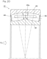
- the bearing for supporting the main shaft is a double-row self-aligning roller bearing 41 having an axially symmetrical structure as shown in Fig. 20 , among rollers 44, 45 in two rows interposed between an inner ring 42 and an outer ring 43, only the rollers 45 in one of the rows that is situated on the rear side with respect to an axial load Fa mainly receive the axial load Fa.
- the rollers 45 in the one row receive both radial load and axial load, while the rollers 44 in the other row receive substantially only the radial load.
- the rollers 45 in the row that receives the radial load and axial load have higher contact surface pressures than those of the rollers 44 in the row that receives only the radial load, and thus the rolling surfaces of the rollers 45 and the raceway surface 43a of the outer ring 43 are more susceptible to surface damage or wear.
- the rollers 45 in the one row have shorter rolling fatigue life than that of the rollers 44 in the other row. Therefore, the substantial service life of the entire bearing is limited by the shorter rolling life of the rollers 45 in the row that receives the axial load.
- the rollers in the other row are arranged at a larger contact angle than that of the rollers in the one row so that the rollers in the other row can support a larger axial load.
- the rollers having the larger contact angle support substantially all the axial load and a part of the radial load, and the rollers having the smaller contact angle support the rest of the radial load.
- the retainer inclination angle ⁇ 2 may be suitably adjusted such that the pocket surfaces of the retainer can hold the rollers at maximum diameter positions of the rollers.
- rollers in the other row having a larger contact angle can serve as the rollers in the row that receives the axial load
- the rollers in the one row having a smaller contact angle can serve as the rollers in the row that receives substantially only the radial load, so as to suitably share loads between the rollers in the respective rows to accommodate either of fatigue loads and extreme load.
- the rollers 4, 5 in the respective left and right rows are retained by retainers 10L, 10R, respectively.
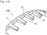
- the retainer 10L for the left row includes an annular portion 11 and a plurality of pillar portions 12 extending from the annular portion 11 toward the left side, and the rollers 4 in the left row are retained in pockets between the respective pillar portions 12.
- the retainer 10R for the right row includes an annular portion 11 and a plurality of pillar portions 12 extending from the annular portion 11 toward the right side, and the rollers 5 in the right row are retained in pockets between the respective pillar portions 12.
- the rollers 4, 5 in the respective left and right rows are asymmetrical rollers having respective maximum diameters D1max, D2max at positions displaced from centers A1, A2 of the roller lengths thereof.
- the maximum diameter D1max of the rollers 4 in the left row is located to the right of the center A1 of the roller length
- the maximum diameter D2max of the rollers 5 in the right row is located to the left of the center A2 of the roller length.
- Induced thrust loads are generated to the rollers 4, 5 in the left and right rows, which are in the form of such asymmetrical rollers.
- the intermediate flange 8 of the inner ring 2 is provided for receiving the induced thrust loads.
- a combination of the asymmetrical rollers 4, 5 and the intermediate flange 8 allows the rollers 4, 5 to be guided accurately because the rollers 4, 5 are guided at three locations, i.e. the inner ring 2, the outer ring 3 and the intermediate flange 8.
- the assumed axial load and radial load refer to an axial load and a radial load that are fatigue loads when an average wind turbine generator in view of conditions such as its power generation capacity and installation location is most normally operated. Therefore, it is conceivable that an optimum ratio of the contact angles may not be 1:3 in a double-row self-aligning roller bearing in the case where the double-row self-aligning roller bearing is used in a wind turbine generator that is different from such an average wind turbine generator in these conditions. However, even in such a case, the optimum ratio of the contact angles falls within a range of 1:4 to 1:2.
- Fig. 10 and Fig. 11 show another embodiment according to the present invention. This embodiment is the same as the first embodiment, except for the features specifically described below.
- the "inclination angle ⁇ 2 of the retainer 10R” refers to an angle formed between e.g. a retainer center line (bearing center axis O) and a center line C2 of a cylindrical surface defined by each pocket surface 12a between pillar portions 12 of the retainer 10R.
- the "inclination angle ⁇ 2 of the retainer” may alternatively be an inclination angle of an outer diameter surface of the retainer 10R or an inclination angle of an inner diameter surface of the retainer 10R.
- the base material of each of the rollers 4, 5 has a surface roughness expressed by an arithmetic roughness Ra ⁇ 0.3 and a root-mean-square gradient R ⁇ q ⁇ 0.05 on an outer surface of the base material.
- Fig. 11 is a schematic sectional view illustrating the structure of the DLC coating 9.
- the DLC coating 9 has a three-layered structure including: (1) a base layer 9a directly formed on a surface of each roller 4, 5 and mainly containing Cr and WC; (2) a mixed layer 9b formed on the base layer 9a and mainly containing WC and DLC; and (3) a surface layer 9c formed on the mixed layer 9b and mainly containing DLC.
- the mixed layer 9b is formed such that the content of WC in the mixed layer is continuously or stepwisely decreases from the base layer 9a side to the surface layer 9c side, while the content of DLC in the mixed layer continuously or stepwisely increases.
- the DLC coating 9 employs the above-described three-layered structure as its film structure so as to avoid sharp change in physical properties (hardness, elastic modulus).
- the mixed layer 9b is an intermediate layer interposed between the base layer and the surface layer.
- WC used in the mixed layer 9b has a hardness and an elastic modulus intermediate between those of Cr and DLC and hardly causes residual stress concentration after film formation.
- the mixed layer 9b has a gradient composition having a decreasing content of WC and an increasing content of DLC from the base layer 9a side to the surface layer 9c side so that the mixed layer has excellent adhesion on the both surfaces facing the base layer 9a and the surface layer 9c.
- WC and DLC are physically bonded in the mixed layer so that breakage in the mixed layer can be prevented.
- the higher content of DLC on the surface layer 9c side contributes to excellent adhesion between the surface layer 9c and the mixed layer 9b.
- the mixed layer 9b is a layer which serves to bond highly non-adhesive DLC to the base layer 9a side by the presence of WC due to the anchor effect.
- the inner diameter Di of the annular portion 11 is, for example, PCD ⁇ 95 to 98%.
- the pillar portions 12 are formed with the tapered portions 13 and the cylindrical pocket surfaces 12a are inclined with respect to the axial direction in which the pillar portions 12 extend, so that each pillar portions has a narrowest width W1 at the distal-most end of the pillar portion 12 and is narrower than a width W2 immediately before the point where the tapered portion 13 starts, when the pillar portion 12 is seen from outside in the retainer radial direction toward the retainer center side as shown in Fig. 16 . Also, the pillar portion 12 has a tip end face 12e having a small radial thickness d ( Fig. 17 ).
- the retainers 10L, 10R may be made of bearing steel or any other ferrous material, or a brass-based material.
- tapered portions 13 are formed so as to eliminate the unnecessary portions and thus do not influence retainment of the rollers 5 and because they achieve weight reduction.
Landscapes
- Engineering & Computer Science (AREA)
- General Engineering & Computer Science (AREA)
- Mechanical Engineering (AREA)
- Life Sciences & Earth Sciences (AREA)
- Sustainable Development (AREA)
- Sustainable Energy (AREA)
- Chemical & Material Sciences (AREA)
- Combustion & Propulsion (AREA)
- Rolling Contact Bearings (AREA)
- Wind Motors (AREA)
- Support Of The Bearing (AREA)
Description
- The present invention relates to a double-row self-aligning roller bearing to be applied to a use in which unequal loads are applied to rollers arranged in two rows in a bearing width direction, for example, as a bearing for supporting a main shaft of a wind turbine generator, industrial machinery or the like.
- On a bearing that supports a main shaft of a wind turbine generator, an axial load due to wind force acts in addition to a radial load due to weights of blades and a rotor head. In the case where the bearing for supporting the main shaft is a double-row self-aligning roller bearing 41 having an axially symmetrical structure as shown in
Fig. 20 , amongrollers inner ring 42 and anouter ring 43, only therollers 45 in one of the rows that is situated on the rear side with respect to an axial load Fa mainly receive the axial load Fa. In other words, therollers 45 in the one row receive both radial load and axial load, while therollers 44 in the other row receive substantially only the radial load. For this reason, therollers 45 in the row that receives the radial load and axial load have higher contact surface pressures than those of therollers 44 in the row that receives only the radial load, and thus the rolling surfaces of therollers 45 and theraceway surface 43a of theouter ring 43 are more susceptible to surface damage or wear. In such a case, therollers 45 in the one row have shorter rolling fatigue life than that of therollers 44 in the other row. Therefore, the substantial service life of the entire bearing is limited by the shorter rolling life of therollers 45 in the row that receives the axial load. - In order to solve this problem, it has been proposed to arrange rollers of different lengths in two rows (see Patent Document 1) or to arrange rollers in two rows at different contact angles (see Patent Document 2) so as to increase the substantial service life of the entire bearing. However, due to requirements of dimensional standards for bearings (ISO Standard; JIS B 1512), it is difficult to increase load capacities of the rollers in the row that receives the axial load to appropriate values by using only one of the two techniques. In other words, since the dimensional standards specify an inner diameter, an outer diameter and a bearing width for each nominal number, the rollers in the row that receives the axial load cannot be too long because the bearing width would exceed a standard value. Similarly, the contact angle of the rollers in the row that receives the axial load cannot be too large because the inner diameter would exceed a standard value.
- Thus, in order to equalize the contact surface pressures on the row that receives the axial load and on the row that receives only the radial load, without making the dimensions of respective parts out of the dimensional standards of bearings, it has been proposed to combine the technique of arranging the rollers of different lengths in two rows and the technique of arranging the rollers in the two rows at different contact angles (see Patent Document 3). In this case, since it is important that the contact angle of the rollers in the row that receives the axial load is increased so as to sufficiently increase the load capacities of the rollers,
Patent Document 3 also proposes an appropriate ratio of the contact angles of the rollers in the respective rows.
It is further kwon in the art of double-row spherical roller bearing that rollers are interposed, between an inner race and an outer race, in two rows beside each other in the widthwise direction of the bearing, a raceway surface of the outer race is spherical, and the outer peripheral surfaces of the two rows of rollers have a cross-sectional shape that conforms to the raceway surface of the outer race. The two rows of rollers have different lengths and the length of the long roller is at least 39% of the bearing width. The ratio of the contact angle of the short roller to the contact angle of the long roller is within the range 1:2 to 1:4. Thus, the bearing can simultaneously receive both axial load and radial load, can be used in applications in which loads of different sizes act on two rows of rollers beside each other in the axial direction, and makes it possible to sufficiently increase, within the constraints of boundary dimensions, the load capacity of the roller in the row that receives the axial load (see Patent Document 4)
There are further known rolling bearings which are designed as a spherical roller bearing, having a bearing inner ring, a bearing outer ring, and having a plurality of rolling elements which are arranged in two axially spaced rows of rollers with different contact angles arranged between the bearing inner ring and the bearing outer ring and designed as identical barrel rollers, the contact angle of the axially inner roller row being greater than the contact angle of the axially outer roller row. In order to achieve a higher load carrying capacity and a longer service life of the rolling bearing, it is provided that the contact angle of the axially outer roller row lies in the range between 2° and 10°, including said limit values, and that the contact angle of the axially inner roller row (7) lies in the range between 7° and 20°, also including said limit values (see Patent Document 5). -
- [Patent Document 1]
WO 2005/050038 - [Patent Document 2]
U.S. Patent Application Publication No. 2014/0112607 - [Patent Document 3]
JP Laid-open Patent Publication No. 2017-180831 - [Patent Document 4]
WO 2017/164325 A1 - [Patent Document 5]
DE 10 2015 204970 A1 - The bearing disclosed in
Patent Document 3 makes it possible to equalize contact surface pressures on the respective rows due to fatigue loads applied day-to-day and thereby to improve substantial service life of the entire bearing. However, the adjustment of the above parameters alone may not sufficiently increase the load capacities in the row of the shorter rollers to accommodate an extreme load that is a possible maximum load anticipated to occur in 50 years of service. - An object of the present invention is to provide a double-row self-aligning roller bearing suitable for a use in which the bearing receives an axial load and a radial load and in which loads having mutually different magnitudes act on rollers arranged in two rows in an axial direction, the bearing being capable of suitably distributing not only fatigue loads but also extreme loads between the rollers in the two rows, within the constraint of the dimensional standards.
- According to the present invention, a double-row self-aligning roller bearing includes:
- an inner ring;
- an outer ring having a spherical raceway surface; and
- a plurality of rollers arranged in two rows in a bearing width direction and interposed between the inner ring and the outer ring, each of the rollers in the two rows having an outer peripheral surface having a cross-sectional shape matching the raceway surface of the outer ring, wherein
- a ratio of a contact angle θ1 of the rollers in one of the rows to a contact angle θ2 of the rollers in the other of the rows falls within a range of 0.25 < θ1/θ2 < 0.5, and
- a ratio of a distance B1 in the bearing width direction from an end face of the bearing on a side of the one of the rows to an intersection of two lines of action defining the contact angles of the two rows, relative to a distance B2 in the bearing width direction from an end face of the bearing on a side of the other of the rows to the intersection falls within a range of 0.5 ≤ B1/B2 ≤ 0.6.
- According to this configuration, the rollers in the other row are arranged at a larger contact angle than that of the rollers in the one row so that the rollers in the other row can support a larger axial load. Where the double-row self-aligning roller bearing is used under a condition where an axial load and a radial load act, the rollers having the larger contact angle support substantially all the axial load and a part of the radial load, and the rollers having the smaller contact angle support the rest of the radial load. By distributing the axial load and the radial load between the rollers in the two rows in such a share proportion, the contact surface pressures on the rollers in the respective rows can be equalized. Thus, it is possible to secure a large load capacity of the entire bearing as well as to increase the substantial service life of the entire bearing.
- Further, a plurality of double-row self-aligning roller bearings having different ratios of contact angles of rollers in respective rows were prepared, and each of the double-row self-aligning roller bearings was analyzed for contact surface pressures on the rollers in the respective rows under an assumed load condition for the case where the bearing is used for supporting a main shaft of a wind turbine generator. As a result, it was found that the bearing having the ratio of the contact angles of 1:3 has the most equalized contact surface pressures on the rollers in the respective rows. The assumed load condition refers to an axial load and a radial load that are fatigue loads when an average wind turbine generator in view of conditions such as its power generation capacity and installation location is most normally operated. Therefore, it is conceivable that an optimum ratio of the contact angles may not be 1:3 in a double-row self-aligning roller bearing used in a wind turbine generator that is different from such an average wind turbine generator in these conditions. However, even in that case, the optimum ratio of the contact angles falls within a range of 1:4 to 1:2. That is, where the ratio of the contact angles of the two rows falls within the range of 0.25 ≤ θ1/θ2 ≤ 0.5, the rollers of the two rows can suitably share the fatigue loads.
- Further, the ratio of the distance B1 in the bearing width direction from the bearing end face on the side of the one row having the smaller contact angle to the intersection of the two lines of action defining the contact angles of the two rows, relative to the distance B2 in the bearing width direction from the bearing end face on the side of the other row having the larger contact angle to the intersection falls within the range of 0.5 ≤ B1/B2 ≤ 0.6, so that the rollers in the one row that supports substantially only the radial load do not have a too small length and fall within the dimensional standard. Therefore, it is possible to prevent the rollers of the one row from having insufficient load capacities, so that they can accommodate even an extreme load which should be anticipated to be applied from various directions. Therefore, the rollers in the two rows can suitably share loads so as to accommodate either of fatigue loads and extreme loads, within the constraint of the dimensional standards.
- In the present invention, a ratio of a length L1 of the rollers in the one of the rows to a length L2 of the rollers in the other of the rows may fall within a range of 0.9 ≤ L1/L2 ≤ 1.0. According to this configuration, the length of the rollers in the row that has the larger contact angle is equal to or greater than the length of the rollers in the row that has the smaller contact angle so as to surely improve the load capacities of the rollers in the row that has the larger contact angle to an axial load. In addition, the length of the rollers in the row that has the smaller contact angle is equal to or greater than 90% of the length of the rollers in the other row so as to ensure that the rollers in the one row that supports substantially only the radial load do not have a too small length and fall within the dimensional standard, as discussed above.
- In the present invention, an inclination angle β2 of a retainer that retains the rollers in the other of the rows may have a relation, relative to a roller maximum diameter angle α2 that is an inclination angle of the rollers in the other of the rows at a point where each of the rollers in the other of the rows has a maximum diameter, expressed by an inequation: 0 ≤ β2 ≤ α2.
- Note that the "inclination angle β2 of the retainer" refers to an angle formed between e.g. a retainer center line (bearing center axis) and a center line of a cylindrical surface defined by each pocket surface between pillar portions of the retainer. The "inclination angle β2 of the retainer" may alternatively be an inclination angle of an outer diameter surface of the retainer or an inclination angle of an inner diameter surface of the retainer.
- Since the rollers in the other of the rows, i.e., the rollers in the rear row with respect to an input direction of the axial load, have a larger maximum diameter angle α2, the retainer inclination angle β2 may be suitably adjusted such that the pocket surfaces of the retainer can hold the rollers at maximum diameter positions of the rollers.
- In that case, where the angles satisfy 0 ≤ β2 ≤ α2, attitude stability of the rollers is not deteriorated.
- Such a retainer shape makes it possible to prevent reduction in ease of assembly, which is particular to an asymmetrical left and right row design, and to stably hold the rollers.
- In the present invention, each of the rollers may have an outer peripheral surface coated with a DLC coating having a multi-layered structure;
- the DLC coating may have a film thickness of 2.0 µm or greater;
- a base material of each of the rollers may have a surface roughness of Ra ≤ 0.3 and a root-mean-square gradient RΔq ≤ 0.05 on an outer surface of the base material; and
- the DLC coating having the multi-layered structure may include layers each having a film hardness, the film hardness stepwisely increasing toward an external-side layer.
- The term "DLC" is an abbreviation for Diamond-like Carbon.
- DLC coating treatment on the outer peripheral surfaces of the rollers improves wear resistance. The DLC coating preferably employs a multi-layered structure which provides excellent adhesion to the base material, and the film thickness is preferably 2.0 µm or greater. Also, the outer peripheral surfaces subjected to the DLC coating may have a surface roughness expressed by values of an arithmetic average roughness Ra of 0.3 Ra or smaller and a root-mean-square gradient RΔq of 0.05 or smaller so that aggressiveness to an opponent material can be reduced. Further, the film hardness of the DLC coating is stepwisely increased in the multi-layered structure so as to achieve high adhesion.
- The double-row self-aligning roller bearing is suitable for supporting a main shaft of a wind turbine generator. Such a double-row self-aligning roller bearing for supporting a main shaft of a wind turbine generator receives a radial load due to weights of blades and a rotor head as well as an axial load due to wind force. Among the rollers arranged in two rows in a bearing width direction, the rollers in one row receive substantially only the radial load, whereas the rollers in the other row receive both the radial load and the axial load. In that case, the rollers in the other row having a larger contact angle can serve as the rollers in the row that receives the axial load, and the rollers in the one row having a smaller contact angle can serve as the rollers in the row that receives substantially only the radial load, so as to suitably share loads between the rollers in the respective rows to accommodate either of fatigue loads and extreme load.
- The present invention encompasses any combination of features as disclosed in the appended claims.
- The present invention will be more clearly understood from the following description of preferred embodiments thereof, when taken in conjunction with the accompanying drawings. However, the embodiments and the drawings are given only for the purpose of illustration and explanation, and are not to be taken as limiting the scope of the present invention in any way whatsoever, which scope is to be determined by the appended claims. In the accompanying drawings, like reference numerals are used to denote like parts throughout the several views. In the figures,
-
Fig. 1 is a sectional view of a double-row self-aligning roller bearing according to a first embodiment of the present invention; -
Fig. 2 illustrates asymmetrical rollers; -
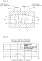
Fig. 3 is a graph showing analytical results of distributions of contact surface pressure on the rollers on the front sides when a synthetic load of an axial load and a radial load is applied to the double-row self-aligning roller bearing and a conventional double-row self-aligning roller bearing; -
Fig. 4 is a graph showing analytical results of distributions of contact surface pressure on the rollers on the rear sides when a synthetic load of an axial load and a radial load is applied to the double-row self-aligning roller bearing and a conventional double-row self-aligning roller bearing; -
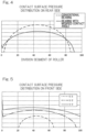
Fig. 5 is a graph showing analytical results of distributions of contact surface pressure on the rollers on the front sides when a synthetic load of an axial load and a radial load is applied to plural types of double-row self-aligning roller bearings having different ratios of contact angles of rollers in respective rows; -
Fig. 6 is a graph showing analytical results of distributions of contact surface pressure on the rollers on the rear sides when a synthetic load of an axial load and a radial load is applied to plural types of double-row self-aligning roller bearings having different ratios of contact angles of rollers in respective rows; -
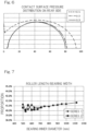
Fig. 7 shows ratios of roller lengths to bearing widths for plural types of conventional double-row self-aligning roller bearings in the same graph; -
Fig. 8 is a partial perspective view of an example of a main shaft support device of a wind turbine generator; -
Fig. 9 is a cutaway side view of the main shaft support device; -
Fig. 10 is a sectional view of a double-row self-aligning roller bearing according to another embodiment of the present invention; -
Fig. 11 illustrates features of a DLC coating on a surface layer of a roller of the double-row self-aligning roller bearing; -
Fig. 12 is a perspective view of an example of a retainer for a double-row self-aligning roller bearing according to one of the embodiments; -
Fig. 13 is a partially enlarged cutaway plan view of the retainer; -
Fig. 14 is a sectional view showing a relation between a pocket of the retainer and a roller; -
Fig. 15 is a partial sectional view of the retainer; -
Fig. 16 is a partial plan view of the retainer; -
Fig. 17 is a sectional view of a pillar portion of the retainer; -
Fig. 18 is a partial perspective view of the retainer; -
Fig. 19 is a partial perspective view of a variant of the retainer; and -
Fig. 20 is a sectional view of a conventional and general double-row self-aligning roller bearing. - A double-row self-aligning roller bearing (hereinafter, sometimes simply referred to as "bearing") 1 according to a first embodiment of the present invention will be described with reference to
Fig. 1 . The double-row self-aligningroller bearing 1 includes: aninner ring 2; anouter ring 3; androllers outer ring 3 has aspherical raceway surface 3a, and each of therollers raceway surface 3a of theouter ring 3. In other words, the outer peripheral surfaces of therollers raceway surface 3a of theouter ring 3 about center lines C1, C2. Theinner ring 2 is formed withraceway surfaces rollers inner ring 2 is provided with flanges (small flanges) 6, 7 at opposite ends of its outer peripheral surface. Theinner ring 2 is provided with anintermediate flange 8 at a center portion of the outer peripheral surface, that is, at a portion between therollers 4 in the left row and therollers 5 in the right row. Note that the terms "left" and "right" used herein merely indicate a relative positional relation in an axial direction of the bearing for the sake of convenience. In this description, the words "left" and "right" correspond to the left and right, respectively, throughout the drawings for ease of understanding. - The
rollers retainers retainer 10L for the left row includes anannular portion 11 and a plurality ofpillar portions 12 extending from theannular portion 11 toward the left side, and therollers 4 in the left row are retained in pockets between therespective pillar portions 12. Theretainer 10R for the right row includes anannular portion 11 and a plurality ofpillar portions 12 extending from theannular portion 11 toward the right side, and therollers 5 in the right row are retained in pockets between therespective pillar portions 12. - As exaggeratedly shown in
Fig. 2 , therollers rollers 4 in the left row is located to the right of the center A1 of the roller length, and the maximum diameter D2max of therollers 5 in the right row is located to the left of the center A2 of the roller length. Induced thrust loads are generated to therollers intermediate flange 8 of theinner ring 2 is provided for receiving the induced thrust loads. A combination of theasymmetrical rollers intermediate flange 8 allows therollers rollers inner ring 2, theouter ring 3 and theintermediate flange 8. - As shown in
Fig. 1 , therollers rollers 5 in the right row is greater than the contact angle θ1 of therollers 4 in the left row. A ratio of the contact angle θ1 of therollers 4 in the left row to the contact angle θ2 of therollers 5 in the right row is set within the range of 1:4 to 1:2, i.e., the range of 0.25 ≤ θ1/θ2 ≤ 0.5. The most preferable ratio of the contact angles θ1, θ2 is 1:3 (θ1/θ2 = 0.333), the reason for which will be explained later. Specifically, the contact angle θ1 falls within a range, for example, from 3° to 6° (preferably θ1 = 5°). The contact angle θ2 falls within a range, for example, from 12° to 18° (preferably θ2 = 15°). - The
rollers 4 in the left row and therollers 5 in the right row have equal maximum diameters D1max, D2max and different lengths L1, L2 along the center lines C1, C2. The length L2 of thelonger rollers 5 is preferably 39% or more of a bearing width B (a distance in the bearing width direction from a bearing end face E1 on the left row side to a bearing end face E2 on the right row side). However, the length L1 of therollers 4 in the left row and the length L2 of therollers 5 in the right row may be equal. Having said that, as in the illustrated example, where the length L2 of the rollers in the row that has the larger contact angle is longer than the length L1 of the rollers in the row that has the smaller contact angle, the rollers in the row that has the larger contact angle have even greater load capacities to receive an axial load. - The position of an intersection P in the bearing width direction at which two lines of action S1, S2 defining the contact angles θ1, θ2 of the respective rows intersect is displaced by a distance K toward a side of the
rollers 4 having the smaller contact angle from a center position Q of theintermediate flange 8 in the bearing width direction. This makes it possible to increase the contact angle θ2 of thelonger rollers 5 without making thelonger rollers 5 unnecessarily long. It should be noted that the lines of action S1, S2 are defined as lines along which a synthetic force of forces acting on contact portions between therollers outer rings - According to the invention, the position of the intersection P in the bearing width direction is set such that a ratio of the distance B1 in the bearing width direction from the bearing end face E1 on the side of the left row having the smaller contact angle to the intersection P, relative to the distance B2 in the bearing width direction from the bearing end face E2 on the side of the right row having the larger contact angle to the intersection P falls within the range of 0.5 ≤B1/B2≤0.6.
- A
bearing 1 having this configuration may be applied to a use in which the bearing receives an axial load and a radial load, and loads having mutually different magnitudes act on the rollers in the left and right rows (for example, as a bearing for supporting a main shaft of a wind turbine generator). In such a case, thebearing 1 is installed such that therollers 4 in the left row are located on a side close to rotor blades (on the front side, i.e., the left side inFig. 1 ) and therollers 5 in the right row are located on a side away from the rotor blades (on the rear side, i.e., the right side inFig. 1 ). In this case, an axial load Fa from the main shaft is applied in a direction from the front side toward the rear side. Thus, therollers 5 in the right row that has the larger contact angle θ2 support substantially all the axial load and a part of the radial load, and therollers 4 in the left row that has the smaller contact angle θ1 support the rest of the radial load. - Where the ratio of the distance B1 to the distance B2 in the bearing width direction falls within the range of 0.5 ≤ B1/B2 ≤ 0.6, the length L1 of the rollers in the left row that supports substantially only the radial load is not too short and falls within the dimensional standard. If the rollers in one of the rows have a too small length, the rollers would have insufficient load capacities, which may lead to reduced service life of the bearing due to edge stress occurring at opposite ends of the rollers upon application of a very large load, such as an extreme load, from a radial direction. In contrast, the
bearing 1 according to the present embodiment makes it possible to prevent the rollers of the one row from having insufficient load capacities, such that they can accommodate even an extreme load which should be anticipated to be applied from various directions. Therefore, according to thebearing 1, the rollers in the two rows can suitably share loads so as to accommodate either of fatigue loads and extreme loads, within the constraint of the dimensional standards. - Although the length L2 of the rollers in the other row (in this example, in the right row) is preferably longer than the length L1 of the rollers in the one row (in this example, in the left row) as described above, it is more preferable that the ratio of L1 to L2 falls within the range of 0.9 ≤ L1/L2 < 1.0 so as not to make the length L1 of the rollers in the left row too short.
- Below is the reason why the ratio of the contact angles of the rollers in the two rows should fall within the range from 0.25 to 0.5. For a conventional double-row self-aligning
roller bearing 41 shown inFig. 10 and the double-row self-aligningroller bearing 1 of the present invention shown inFig. 1 , contact surface pressures on the rollers in the left and right rows were analyzed under a synthetic load of an axial load and a radial load assumed for the case where each bearing is used for supporting a main shaft of a wind turbine generator.Fig. 3 shows contact surface pressure distributions on the rollers on the front sides, i.e. therollers Fig. 4 shows the analytical result of contact surface pressure distributions on the rollers on the rear sides, i.e. on therollers - From the results in
Fig. 3 andFig. 4 , the following is revealed. The conventional bearing inFig. 10 has lower contact surface pressures on the front side and higher contact surface pressures on the rear side, and thus loads are unequally shared between the front side and the rear side. In contrast, the bearing with modified contact angles inFig. 1 has equalized contact surface pressures with reduced difference between the contact surface pressures in respective rows because the contact surface pressures are distributed over the entirety of the rollers on the front side, reducing a maximum value of the contact surface pressures on the rear side. - Three types of double-row self-aligning roller bearings each having a different ratio of the contact angle θ1 of the
rollers 4 in the left row and the contact angle θ2 of therollers 5 in the right row were prepared, and contact surface pressures on the rollers in the left and right rows were analyzed in the same way.Fig. 5 shows the analytical result of contact surface pressure distributions on the rollers on the front sides, i.e. on therollers 4 in the left rows, andFig. 6 shows the analytical result of contact surface pressure distributions on the rollers on the rear sides, i.e. on therollers 5 in the right rows. The bearing having the ratio of the contact angles of 1:1 is a conventional one, and the bearings having the ratios of the contact angles of 1:2, 1:3 are those of the present invention which have modified contact angles. - From the results in
Fig. 5 andFig. 6 , the following is revealed. When the contact surface pressure distributions are compared for the respective ratios of the contact angles, the bearing having the ratio of the contact angles of 1:3 has the most equalized contact surface pressures between the front side and the rear side. The bearing having the ratio of the contact angles of 1:2 is less equalized when compared with the bearing having the ratio of the contact angles of 1:3 but is sufficiently equalized when compared with the bearing having the ratio of the contact angles of 1:1. As can be seem fromFig. 1 , if the contact angle θ2 of therollers 5 is made larger, it becomes difficult to dispose thelonger rollers 5 because the thickness of theinner ring 2 is made too thin due to the dimensional constraint. In view of these, it is desirable to set the ratio of the contact angles to be equal to or greater than 1:4 and equal to or less than 1:2. - It should be noted that the assumed axial load and radial load refer to an axial load and a radial load that are fatigue loads when an average wind turbine generator in view of conditions such as its power generation capacity and installation location is most normally operated. Therefore, it is conceivable that an optimum ratio of the contact angles may not be 1:3 in a double-row self-aligning roller bearing in the case where the double-row self-aligning roller bearing is used in a wind turbine generator that is different from such an average wind turbine generator in these conditions. However, even in such a case, the optimum ratio of the contact angles falls within a range of 1:4 to 1:2.
- Although not essential, a condition that the length L2 of the
longer rollers 5 is equal to or greater than 39% of the bearing width B may be added so as to provide a double-row self-aligning roller bearing that falls within the dimensional standards and has a ratio of the contact angles of the rollers in the respective rows within the above appropriate range. From an investigation of the proportion of the length L2 of therollers 5 relative to the bearing width B in conventional double-row self-aligning roller bearings, it was found that the proportion is equal to or greater than 39%, as shown inFig. 7 . The dimensional standards specify an inner diameter, an outer diameter and a bearing width. -
Fig. 8 and Fig. 9 illustrate an example of a main shaft support device of a wind turbine generator. Acasing 23a of anacelle 23 is horizontally turnably disposed on asupport 21 via a revolving seat bearing 22 (Fig. 9 ). Amain shaft 26 is rotatably fitted within thecasing 23a of thenacelle 23 via mainshaft support bearings 25 disposed in bearinghousings 24, andblades 27 that serve as rotor blades are attached to a portion of themain shaft 26 projected outside of thecasing 23a. The other end of themain shaft 26 is connected to aspeed increasing gear 28, and an output shaft of thespeed increasing gear 28 is coupled to a rotor shaft of apower generator 29. Thenacelle 23 is revolved to any angle by revolvingmotors 30 via reduction gears 31. The illustrated example has two mainshaft support bearings 25 arranged in series but may have a single main shaft support bearing. -
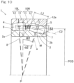
Fig. 10 andFig. 11 show another embodiment according to the present invention. This embodiment is the same as the first embodiment, except for the features specifically described below. - In a double-row self-aligning
roller bearing 1 according to this embodiment, an inclination angle β2 of aretainer 10R that retains therollers 5 in the other row has a relation expressed as 0 ≤ β2 ≤ α2 relative to a roller maximum diameter angle α2 that is an inclination angle of therollers 5 in the other row at a point where each of therollers 5 in the other row has a maximum diameter. - Note that the "inclination angle β2 of the
retainer 10R" refers to an angle formed between e.g. a retainer center line (bearing center axis O) and a center line C2 of a cylindrical surface defined by eachpocket surface 12a betweenpillar portions 12 of theretainer 10R. The "inclination angle β2 of the retainer" may alternatively be an inclination angle of an outer diameter surface of theretainer 10R or an inclination angle of an inner diameter surface of theretainer 10R. - Since the
rollers 5 in the other row, i.e., therollers 5 in the rear row with respect to an input direction of the axial load, have a larger maximum diameter angle α2, the retainer inclination angle β2 may be suitably adjusted such that the pocket surfaces 12a of theretainer 10R can hold therollers 5 at maximum diameter positions of the rollers. - In that case, where the angles satisfy 0 ≤ β2 ≤ α2, attitude stability of the
rollers 5 is not deteriorated. - Such a shape of the
retainer 10R makes it possible to prevent reduction in ease of assembly, which is particular to an asymmetrical left and right row design, and to stably hold therollers 5. - Each of the
rollers raceway surfaces inner ring 2 and theouter ring 3 in the same manner as that of therollers rollers base layer 9a, a mixed layer 9b, and asurface layer 9c provided sequentially from the base material side of therollers roller 5 on the rear side inFig. 11 . - The base material of each of the
rollers - The DLC coating 9 having the multi-layered structure includes the
layers - DLC coating treatment on the outer peripheral surfaces of the
rollers - The material of the
rollers rollers inner ring 2 and theouter ring 3 are made of a ferrous material. The ferrous material may be any steel material that is commonly used for bearing components and may include, for example, high carbon chromium bearing steel, carbon steel, tool steel, and martensite stainless steel. - These bearing components preferably have a Vickers hardness of Hv 650 or higher on their surfaces on which the DLC coating 9 is to be formed. A hardness of Hv 650 or higher can reduce a hardness difference between the base material surfaces and the DLC coating 9 (base layer) so as to improve adhesion.
- Prior to formation of the coating film, a nitride layer is preferably formed by nitriding treatment on the surfaces of the
rollers Hv 1000 or higher so as to further enhance adhesion between the base material surfaces and the DLC coating 9 (base layer). - The base material surfaces of the
rollers base layer 9a is to be formed, have an arithmetic average roughness Ra from 0.1 to 0.3 µm and a root-mean-square gradient RΔq of 0.05 or smaller. RΔq is preferably 0.03 or smaller, and more preferably 0.02 or smaller. The arithmetic average roughness Ra and the root-mean-square gradient RΔq are calculated in accordance with JIS B 0601 and are measured using a contact or non-contact type surface roughness tester. The following specific measurement condition is used:measurement length 4 mm, cutoff 0.8 mm. The base material surfaces having a root-mean-square gradient RΔq of 0.05 or smaller have a gentle peak in a roughness curve and include protrusions having a larger radius of curvature so that local surface pressure can be reduced. Such base material surfaces can also suppress electrical field concentration at a microscopic-level due to roughness during film formation and prevent local change in film thickness and hardness, thereby improving peeling resistance of the hard coating. - Each base material surface preferably has a maximum ridge height Rp which is determined from a roughness curve of the base material surface of 0.4 µm or smaller. The maximum ridge height Rp is determined in accordance with JIS B 0601. The relation between the maximum ridge height Rp determined from the roughness curve and the arithmetic average roughness Ra preferably satisfies 1 ≤ Rp/Ra ≤ 2, and more preferably 1.2 ≤ Rp/Ra ≤ 2.
- The base material surface preferably has a negative skewness Rsk which is determined from the roughness curve. Rsk is an indicator of a degree of distortion and is more preferably -0.2 or lower. Skewness Rsk quantitatively represents the vertical symmetry of an amplitude distribution curve about its mean line, i.e., serves as an indicator of a deviation of the surface roughness from the mean line. Skewness Rsk is determined in accordance with JIS B 0601. A negative value of skewness Rsk indicates that the roughness curve is shaped so as to extend downward (i.e., to define valleys), indicating that the surface has many flat portions. Consequently, the surface has fewer protrusions and is unlikely cause stress concentration due to the projections. Although a technique of reducing roughness such as barrel finishing may be used to remove surface projections by collisions with polishing medium, care should be taken because new protrusions may be formed depending on the processing condition, which may lead to the surface having a positive Rsk.
-
Fig. 11 is a schematic sectional view illustrating the structure of the DLC coating 9. As shown inFig. 11 , the DLC coating 9 has a three-layered structure including: (1) abase layer 9a directly formed on a surface of eachroller base layer 9a and mainly containing WC and DLC; and (3) asurface layer 9c formed on the mixed layer 9b and mainly containing DLC. The mixed layer 9b is formed such that the content of WC in the mixed layer is continuously or stepwisely decreases from thebase layer 9a side to thesurface layer 9c side, while the content of DLC in the mixed layer continuously or stepwisely increases. In the present embodiment, the DLC coating 9 employs the above-described three-layered structure as its film structure so as to avoid sharp change in physical properties (hardness, elastic modulus). - Since the
base layer 9a contains Cr, it is compatible with the base material made of a cemented carbide material or a ferrous material and provides excellent adhesion to the base material in comparison with cases where W, Ti, Si, or Al is used. In addition, WC used in thebase layer 9a has a hardness and an elastic modulus intermediate between those of Cr and DLC and hardly causes residual stress concentration after film formation. Further, thebase layer 9a preferably has a gradient composition having a decreasing content of Cr and an increasing content of WC from the roller surface side to the mixed layer 9b side. This provides excellent adhesion on the both surfaces facing the roller surface and the mixed layer 9b. - The mixed layer 9b is an intermediate layer interposed between the base layer and the surface layer. As discussed above, WC used in the mixed layer 9b has a hardness and an elastic modulus intermediate between those of Cr and DLC and hardly causes residual stress concentration after film formation. The mixed layer 9b has a gradient composition having a decreasing content of WC and an increasing content of DLC from the
base layer 9a side to thesurface layer 9c side so that the mixed layer has excellent adhesion on the both surfaces facing thebase layer 9a and thesurface layer 9c. Also, WC and DLC are physically bonded in the mixed layer so that breakage in the mixed layer can be prevented. Further, the higher content of DLC on thesurface layer 9c side contributes to excellent adhesion between thesurface layer 9c and the mixed layer 9b. The mixed layer 9b is a layer which serves to bond highly non-adhesive DLC to thebase layer 9a side by the presence of WC due to the anchor effect. - The
surface layer 9c is a film that mainly contains DLC. Thesurface layer 9c preferably includes agradient layer portion 9d which is located on the side adjacent to the mixed layer 9b and has continuously or stepwisely increasing hardness from the mixed layer 9b side. This portion can be formed by continuously or stepwisely changing (increasing) a bias voltage so as to avoid a sharp change in the bias voltage, where different bias voltages are applied to the mixed layer 9b and to thesurface layer 9c. Thegradient layer portion 9d has a graded hardness as a consequence of changing the bias voltage in such a manner. The reason why the hardness increases continuously or stepwisely is that a composition ratio of the graphite structure (SP2) and the diamond structure (SP3) in the DLC structure shifts toward the latter due to the increasing bias voltage. This eliminates a large hardness difference between the mixed layer and the surface layer, further enhancing the adhesion between the mixed layer 9b and thesurface layer 9c. - The DLC coating 9 preferably has a film thickness (total thickness of the three layers) from 0.5 to 3.0 µm. A coating having a film thickness below 0.5 µm may be poor in wear resistance and mechanical strength, whereas a coating having a film thickness above 5.0 µm may be easily peeled off. Further, a proportion of the thickness of the
surface layer 9c in the film thickness of the DLC coating 9 is preferably 0.8 or lower. Where the proportion exceeds 0.8, the gradient structure for physically bonding WC and DLC in the mixed layer 9b tends to be discontinuous, leading to deterioration of adhesion. - The DLC coating 9 having the three-layered structure including the
base layer 9a, the mixed layer 9b, and thesurface layer 9c of the above compositions provides excellent peeling resistance. -
Fig. 12 to Fig. 19 show an exemplary configuration of theretainer 10R on the rear side. Theretainer 10L (Fig. 1 ) on the front side shares common features, which will be described below with reference toFig. 12 to Fig. 19 , with theretainer 10R on the rear side in the features, and overlapping description is omitted. Also, theretainer 10R having the exemplary configuration may be applied either to the first embodiment or the embodiment ofFig. 10 . - In
Fig. 12 , eachpillar portion 12 of theretainer 10R has a lengthwise portion that is shaped from a columnar portion having a same basic cross-sectional shape (a shape illustrated inFig. 14 with imaginary lines) by cutting so as to have acylindrical pocket surface 12a and is provided with a taperedportion 13 at the tip end thereof. The basic cross-sectional shape is defined by an outerperipheral surface 12b and an innerperipheral surface 12c each defining a part of a cylindrical surface andflat side surfaces 12d extending in the radial direction on opposite sides. The cylindrical surface defining thepocket surface 12a has a diameter slightly larger than the maximum diameter of eachroller 5. Thepocket surface 12a is a cylindrical surface about the center line C2 (Fig. 1 ,Fig. 10 ). As shown inFig. 17 , the center line C2 is inclined with respect to the direction of extension of thepillar portion 12 such that the tip end of each pillar portion extends toward the inner diameter side. - The
retainer 10R shown inFig. 13 has an outer diameter Do, an inner diameter Di, and a pillar portion length L that are optimized as follows. - The outer diameter Do of the
annular portion 11 of theretainer 10R is larger than a pitch circle diameter PCD of the row of therollers 5, and the inner diameter Di of theannular portion 11 is smaller than the pitch circle diameter PCD (Fig. 10 ). - The outer diameter Do of the
annular portion 11 is, for example, PCD × 102 to 105%. - The inner diameter Di of the
annular portion 11 is, for example, PCD × 95 to 98%. - The length L of each
pillar portion 12, specifically, the length L of each of parts of thepillar portions 12 that definepockets 7, is equal to or smaller than 65% of the length L2 of the rollers (Fig. 1 ,Fig. 10 ). - Each tapered portion 13 (
Fig. 12 to Fig. 13 ,Fig. 15 to Fig. 17 ) is formed on the outer diameter surface at the tip end of eachpillar portion 12 so as to be inclined toward a retainer inner diameter side as it reaches a distal-most end of the pillar portion. The taperedportion 13 starts at a position on a line "a" (illustrated inFig. 15 with a dashed line) that extends so as to form the maximum diameter angle of therollers 5 or at a position on the side of the tip end of each pillar portion with respect to the line "a." In other words, the taperedportion 13 starts at a position M (Fig. 10 ) on the center line C2 at which eachroller 5 has its maximum diameter or at a position on the side of the tip end of each pillar portion with respect to the position M. - The
pillar portions 12 are formed with thetapered portions 13 and the cylindrical pocket surfaces 12a are inclined with respect to the axial direction in which thepillar portions 12 extend, so that each pillar portions has a narrowest width W1 at the distal-most end of thepillar portion 12 and is narrower than a width W2 immediately before the point where the taperedportion 13 starts, when thepillar portion 12 is seen from outside in the retainer radial direction toward the retainer center side as shown inFig. 16 . Also, thepillar portion 12 has atip end face 12e having a small radial thickness d (Fig. 17 ). - The
retainers - According to the
retainer 10R having this configuration, the cylindrical pocket surfaces 12a of thepillar portions 12 allow therollers 5 to be securely retained. Also, provision of the taperedportions 13 improves ease of assembly of therollers 5. - The relation between the
tapered portions 13 and ease of assembly of therollers 5 will be described. The center line C2 of each cylindrical surface that defines thepocket surface 12a of thepillar portion 12 is inclined with respect to the direction of extension of thepillar portion 12 such that the tip end of the pillar portion extends toward the inner diameter side. For this reason, where the tapered portions 13 (seeFig. 18 ) are not provided as in the example ofFig. 19 , each pillar portion has a largest width at the distal-most end of the pillar portion when thepillar portion 12 is viewed from outside in the retainer radial direction toward the retainer center side. Therefore, the outer diameter portions at the tip ends of thewide pillar portions 12 hinder smooth insertion of therollers 5 into thepockets 15, and the outer diameter portions at the tip ends of thewide pillar portions 12 are unnecessary portions that do not provide any good effect on its strength and/or functions. - In this embodiment, the tip end of each pillar portion has a reduced radial width W1 (
Fig. 16 ) and a reduced radial thickness d (Fig. 17 ) due to provision of the taperedportion 13. This can improve ease of assembly of therollers 5 and reduce the weight of theretainer 10R. Improvement in ease of assembly of therollers 5 eliminates the necessity of largely deforming theretainer 10R upon assembling, so that shape distortion due to the deformation of theretainer 10R can be prevented. - It is preferable to provide the tapered
portions 13 because thetapered portions 13 are formed so as to eliminate the unnecessary portions and thus do not influence retainment of therollers 5 and because they achieve weight reduction. - However, since too long tapered
portions 13 would deteriorate retainment of therollers 5, each of the tapered portions starts at a position M (Fig. 16 ) at which eachroller 5 has its maximum diameter or at a position on the side of the tip end of the pillar portion with respect to the position M. Thus, therollers 5 are securely retained. - In view of ease of assembly of the
rollers 5, each tip end of the taperedportions 13 preferably has a radial thickness d (Fig. 17 ) as small as possible. However, since it is necessary to keep plain surfaces at the tip ends in order to form the cylindrical pocket surfaces 12a from the tip end side of thepillar portions 12 by drilling, it is preferable to make each tapered portion as thin as possible without hindering processing. - Although the description is made with reference to the
retainer 10R on the rear side, theretainer 10L on the front side has the same features of the retainer shape and provides the same advantages as those of theretainer 1 0R on the rear side. - These
retainers tapered portions 13 at the tip ends of thepillar portions 12, for instance, as in the example illustrated inFig. 19 , or may be shaped such that the center line C2 of the cylindrical surface defining eachpocket surface 12a is not inclined with respect to the direction of extension of thepillar portions 12. - Although the present invention has been fully described in connection with the embodiments thereof, the embodiments disclosed herein are merely examples in all respects, and are not to be taken as limiting the scope of the present invention in any way whatsoever. The scope of the present invention is to be determined by the appended claims, not by the above description, and is intended to include any change made within the scope of claims.
-
- 1, 1A, 1B ···· Double-row self-aligning roller bearing
- 2 ···· Inner ring
- 3 ···· Outer ring
- 3a ···· Raceway surface
- 4, 5 ···· Roller
- 6, 7 ···· Small flange
- 8 ···· Intermediate flange
- 9 ···· DLC coating
- 11 ···· Annular portion
- 12 ···· Pillar portion
- 13 ···· Tapered portion
- 15 ···· Pocket
- 26 ···· Main shaft
- A1, A2 ···· Center of the roller length
- B ···· Bearing width
- B1, B2 ···· Distance in a bearing width direction from a bearing end face to an intersection of lines of action
- D1max, D2max ···· Maximum diameter
- E1, E2 ···· End face of the bearing
- L1, L2 ···· Length of the roller
- P ···· Intersection of lines of action
- θ1,θ2 ···· Contact angle
Claims (5)
- A double-row self-aligning roller bearing comprising:an inner ring;an outer ring having a spherical raceway surface; anda plurality of rollers arranged in two rows in a bearing width direction and interposed between the inner ring and the outer ring, each of the rollers in the two rows having an outer peripheral surface having a cross-sectional shape matching the raceway surface of the outer ring, whereina ratio of a contact angle θ1 of the rollers in one of the rows to a contact angle θ2 of the rollers in the other of the rows falls within a range of 0.25 ≤ θ1/θ2 < 0.5, andcharacterized in that
a ratio of a distance B1 in the bearing width direction from an end face of the bearing on a side of the one of the rows to an intersection of two lines of action defining the contact angles of the two rows, relative to a distance B2 in the bearing width direction from an end face of the bearing on a side of the other of the rows to the intersection falls within a range of 0.5 ≤ B1/B2 ≤ 0.6. - The double-row self-aligning roller bearing as claimed in claim 1, wherein a ratio of a length L1 of the rollers in the one of the rows to a length L2 of the rollers in the other of the rows falls within a range of 0.9 ≤ L1/L2 ≤ 1.0.
- The double-row self-aligning roller bearing as claimed in claim 1 or 2, wherein an inclination angle β2 of a retainer that retains the rollers in the other of the rows has a relation, relative to a roller maximum diameter angle α2 that is an inclination angle of the rollers in the other of the rows at a point where each of the rollers in the other of the rows has a maximum diameter, expressed by an inequation: 0 ≤ β2 ≤ α2.
- The double-row self-aligning roller bearing as claimed in any one of claims 1 to 3, wherein each of the rollers has an outer peripheral surface coated with a DLC coating having a multi-layered structure;the DLC coating has a film thickness of 2.0 µm or greater;a base material of each of the rollers has a surface roughness of Ra ≤ 0.3 and a root-mean-square gradient RΔq ≤ 0.05 on an outer surface of the base material; andthe DLC coating having the multi-layered structure includes layers each having a film hardness, the film hardness stepwisely increasing toward an external-side layer.
- The double-row self-aligning roller bearing as claimed in any one of claims 1 to 4, wherein the double-row self-aligning roller bearing is used for supporting a main shaft of a wind turbine generator.
Applications Claiming Priority (3)
| Application Number | Priority Date | Filing Date | Title |
|---|---|---|---|
| JP2018081203 | 2018-04-20 | ||
| JP2019072707A JP7488633B2 (en) | 2018-04-20 | 2019-04-05 | Double row spherical roller bearing |
| PCT/JP2019/016453 WO2019203265A1 (en) | 2018-04-20 | 2019-04-17 | Double-row self-aligning roller bearing |
Publications (3)
| Publication Number | Publication Date |
|---|---|
| EP3783237A1 EP3783237A1 (en) | 2021-02-24 |
| EP3783237A4 EP3783237A4 (en) | 2021-12-22 |
| EP3783237B1 true EP3783237B1 (en) | 2023-10-11 |
Family
ID=68388976
Family Applications (1)
| Application Number | Title | Priority Date | Filing Date |
|---|---|---|---|
| EP19788217.8A Active EP3783237B1 (en) | 2018-04-20 | 2019-04-17 | Double-row self-aligning roller bearing |
Country Status (2)
| Country | Link |
|---|---|
| EP (1) | EP3783237B1 (en) |
| JP (1) | JP7488633B2 (en) |
Families Citing this family (1)
| Publication number | Priority date | Publication date | Assignee | Title |
|---|---|---|---|---|
| AT524591B1 (en) | 2021-05-14 | 2022-07-15 | Miba Gleitlager Austria Gmbh | Gondola for a wind turbine |
Family Cites Families (5)
| Publication number | Priority date | Publication date | Assignee | Title |
|---|---|---|---|---|
| JP5620860B2 (en) * | 2010-03-30 | 2014-11-05 | Ntn株式会社 | Rolling bearing |
| CN102822546B (en) * | 2010-03-30 | 2015-10-14 | Ntn株式会社 | Rolling bearing |
| DE102015204970A1 (en) * | 2015-03-19 | 2016-09-22 | Schaeffler Technologies AG & Co. KG | Rolling, for example, a wind turbine |
| JP2016186355A (en) * | 2015-03-27 | 2016-10-27 | Ntn株式会社 | Rolling bearing cage and rolling bearing |
| WO2017164325A1 (en) * | 2016-03-24 | 2017-09-28 | Ntn株式会社 | Double-row spherical roller bearing |
-
2019
- 2019-04-05 JP JP2019072707A patent/JP7488633B2/en active Active
- 2019-04-17 EP EP19788217.8A patent/EP3783237B1/en active Active
Also Published As
| Publication number | Publication date |
|---|---|
| JP7488633B2 (en) | 2024-05-22 |
| JP2019190658A (en) | 2019-10-31 |
| EP3783237A4 (en) | 2021-12-22 |
| EP3783237A1 (en) | 2021-02-24 |
Similar Documents
| Publication | Publication Date | Title |
|---|---|---|
| EP1673553B1 (en) | Epicyclic gear system | |
| EP3434918B1 (en) | Double-row self-aligning roller bearing | |
| US7918649B2 (en) | Double-row self-aligning roller bearing and device for supporting wind turbine generator main shaft | |
| US11306776B2 (en) | Double-row self-aligning roller bearing | |
| WO2017164325A1 (en) | Double-row spherical roller bearing | |
| US11773901B2 (en) | Self-aligning roller bearing | |
| US10697492B2 (en) | Double-row self-aligning roller bearing | |
| EP3783237B1 (en) | Double-row self-aligning roller bearing | |
| US11187266B2 (en) | Double-row self-aligning roller bearing | |
| JP2006189133A (en) | Thrust roller bearing | |
| JP2005155838A (en) | Roller bearing | |
| CN118234964A (en) | Mechanical roller bearing | |
| JP2006112560A (en) | Tapered roller bearing |
Legal Events
| Date | Code | Title | Description |
|---|---|---|---|
| STAA | Information on the status of an ep patent application or granted ep patent |
Free format text: STATUS: THE INTERNATIONAL PUBLICATION HAS BEEN MADE |
|
| PUAI | Public reference made under article 153(3) epc to a published international application that has entered the european phase |
Free format text: ORIGINAL CODE: 0009012 |
|
| STAA | Information on the status of an ep patent application or granted ep patent |
Free format text: STATUS: REQUEST FOR EXAMINATION WAS MADE |
|
| 17P | Request for examination filed |
Effective date: 20201103 |
|
| AK | Designated contracting states |
Kind code of ref document: A1 Designated state(s): AL AT BE BG CH CY CZ DE DK EE ES FI FR GB GR HR HU IE IS IT LI LT LU LV MC MK MT NL NO PL PT RO RS SE SI SK SM TR |
|
| AX | Request for extension of the european patent |
Extension state: BA ME |
|
| DAV | Request for validation of the european patent (deleted) | ||
| DAX | Request for extension of the european patent (deleted) | ||
| A4 | Supplementary search report drawn up and despatched |
Effective date: 20211118 |
|
| RIC1 | Information provided on ipc code assigned before grant |
Ipc: F16C 19/38 20060101ALI20211112BHEP Ipc: F03D 80/70 20160101ALI20211112BHEP Ipc: F16C 23/08 20060101AFI20211112BHEP |
|
| GRAP | Despatch of communication of intention to grant a patent |
Free format text: ORIGINAL CODE: EPIDOSNIGR1 |
|
| STAA | Information on the status of an ep patent application or granted ep patent |
Free format text: STATUS: GRANT OF PATENT IS INTENDED |
|
| INTG | Intention to grant announced |
Effective date: 20230426 |
|
| GRAS | Grant fee paid |
Free format text: ORIGINAL CODE: EPIDOSNIGR3 |
|
| GRAA | (expected) grant |
Free format text: ORIGINAL CODE: 0009210 |
|
| STAA | Information on the status of an ep patent application or granted ep patent |
Free format text: STATUS: THE PATENT HAS BEEN GRANTED |
|
| AK | Designated contracting states |
Kind code of ref document: B1 Designated state(s): AL AT BE BG CH CY CZ DE DK EE ES FI FR GB GR HR HU IE IS IT LI LT LU LV MC MK MT NL NO PL PT RO RS SE SI SK SM TR |
|
| REG | Reference to a national code |
Ref country code: GB Ref legal event code: FG4D |
|
| REG | Reference to a national code |
Ref country code: CH Ref legal event code: EP |
|
| REG | Reference to a national code |
Ref country code: DE Ref legal event code: R096 Ref document number: 602019039226 Country of ref document: DE |
|
| REG | Reference to a national code |
Ref country code: IE Ref legal event code: FG4D |
|
| REG | Reference to a national code |
Ref country code: DK Ref legal event code: T3 Effective date: 20240104 |
|
| REG | Reference to a national code |
Ref country code: LT Ref legal event code: MG9D |
|
| REG | Reference to a national code |
Ref country code: NL Ref legal event code: MP Effective date: 20231011 |
|
| REG | Reference to a national code |
Ref country code: AT Ref legal event code: MK05 Ref document number: 1620490 Country of ref document: AT Kind code of ref document: T Effective date: 20231011 |
|
| PG25 | Lapsed in a contracting state [announced via postgrant information from national office to epo] |
Ref country code: NL Free format text: LAPSE BECAUSE OF FAILURE TO SUBMIT A TRANSLATION OF THE DESCRIPTION OR TO PAY THE FEE WITHIN THE PRESCRIBED TIME-LIMIT Effective date: 20231011 |
|
| PG25 | Lapsed in a contracting state [announced via postgrant information from national office to epo] |
Ref country code: GR Free format text: LAPSE BECAUSE OF FAILURE TO SUBMIT A TRANSLATION OF THE DESCRIPTION OR TO PAY THE FEE WITHIN THE PRESCRIBED TIME-LIMIT Effective date: 20240112 |
|
| PG25 | Lapsed in a contracting state [announced via postgrant information from national office to epo] |
Ref country code: IS Free format text: LAPSE BECAUSE OF FAILURE TO SUBMIT A TRANSLATION OF THE DESCRIPTION OR TO PAY THE FEE WITHIN THE PRESCRIBED TIME-LIMIT Effective date: 20240211 |
|
| PG25 | Lapsed in a contracting state [announced via postgrant information from national office to epo] |
Ref country code: LT Free format text: LAPSE BECAUSE OF FAILURE TO SUBMIT A TRANSLATION OF THE DESCRIPTION OR TO PAY THE FEE WITHIN THE PRESCRIBED TIME-LIMIT Effective date: 20231011 |
|
| PG25 | Lapsed in a contracting state [announced via postgrant information from national office to epo] |
Ref country code: AT Free format text: LAPSE BECAUSE OF FAILURE TO SUBMIT A TRANSLATION OF THE DESCRIPTION OR TO PAY THE FEE WITHIN THE PRESCRIBED TIME-LIMIT Effective date: 20231011 |
|
| PG25 | Lapsed in a contracting state [announced via postgrant information from national office to epo] |
Ref country code: ES Free format text: LAPSE BECAUSE OF FAILURE TO SUBMIT A TRANSLATION OF THE DESCRIPTION OR TO PAY THE FEE WITHIN THE PRESCRIBED TIME-LIMIT Effective date: 20231011 |
|
| PG25 | Lapsed in a contracting state [announced via postgrant information from national office to epo] |
Ref country code: LT Free format text: LAPSE BECAUSE OF FAILURE TO SUBMIT A TRANSLATION OF THE DESCRIPTION OR TO PAY THE FEE WITHIN THE PRESCRIBED TIME-LIMIT Effective date: 20231011 Ref country code: IS Free format text: LAPSE BECAUSE OF FAILURE TO SUBMIT A TRANSLATION OF THE DESCRIPTION OR TO PAY THE FEE WITHIN THE PRESCRIBED TIME-LIMIT Effective date: 20240211 Ref country code: GR Free format text: LAPSE BECAUSE OF FAILURE TO SUBMIT A TRANSLATION OF THE DESCRIPTION OR TO PAY THE FEE WITHIN THE PRESCRIBED TIME-LIMIT Effective date: 20240112 Ref country code: ES Free format text: LAPSE BECAUSE OF FAILURE TO SUBMIT A TRANSLATION OF THE DESCRIPTION OR TO PAY THE FEE WITHIN THE PRESCRIBED TIME-LIMIT Effective date: 20231011 Ref country code: BG Free format text: LAPSE BECAUSE OF FAILURE TO SUBMIT A TRANSLATION OF THE DESCRIPTION OR TO PAY THE FEE WITHIN THE PRESCRIBED TIME-LIMIT Effective date: 20240111 Ref country code: AT Free format text: LAPSE BECAUSE OF FAILURE TO SUBMIT A TRANSLATION OF THE DESCRIPTION OR TO PAY THE FEE WITHIN THE PRESCRIBED TIME-LIMIT Effective date: 20231011 Ref country code: PT Free format text: LAPSE BECAUSE OF FAILURE TO SUBMIT A TRANSLATION OF THE DESCRIPTION OR TO PAY THE FEE WITHIN THE PRESCRIBED TIME-LIMIT Effective date: 20240212 |
|
| PG25 | Lapsed in a contracting state [announced via postgrant information from national office to epo] |
Ref country code: SE Free format text: LAPSE BECAUSE OF FAILURE TO SUBMIT A TRANSLATION OF THE DESCRIPTION OR TO PAY THE FEE WITHIN THE PRESCRIBED TIME-LIMIT Effective date: 20231011 Ref country code: RS Free format text: LAPSE BECAUSE OF FAILURE TO SUBMIT A TRANSLATION OF THE DESCRIPTION OR TO PAY THE FEE WITHIN THE PRESCRIBED TIME-LIMIT Effective date: 20231011 Ref country code: PL Free format text: LAPSE BECAUSE OF FAILURE TO SUBMIT A TRANSLATION OF THE DESCRIPTION OR TO PAY THE FEE WITHIN THE PRESCRIBED TIME-LIMIT Effective date: 20231011 Ref country code: NO Free format text: LAPSE BECAUSE OF FAILURE TO SUBMIT A TRANSLATION OF THE DESCRIPTION OR TO PAY THE FEE WITHIN THE PRESCRIBED TIME-LIMIT Effective date: 20240111 Ref country code: LV Free format text: LAPSE BECAUSE OF FAILURE TO SUBMIT A TRANSLATION OF THE DESCRIPTION OR TO PAY THE FEE WITHIN THE PRESCRIBED TIME-LIMIT Effective date: 20231011 Ref country code: HR Free format text: LAPSE BECAUSE OF FAILURE TO SUBMIT A TRANSLATION OF THE DESCRIPTION OR TO PAY THE FEE WITHIN THE PRESCRIBED TIME-LIMIT Effective date: 20231011 |
|
| PGFP | Annual fee paid to national office [announced via postgrant information from national office to epo] |
Ref country code: DE Payment date: 20240313 Year of fee payment: 6 |
|
| PGFP | Annual fee paid to national office [announced via postgrant information from national office to epo] |
Ref country code: DK Payment date: 20240411 Year of fee payment: 6 |
|
| REG | Reference to a national code |
Ref country code: DE Ref legal event code: R097 Ref document number: 602019039226 Country of ref document: DE |
|
| PG25 | Lapsed in a contracting state [announced via postgrant information from national office to epo] |
Ref country code: CZ Free format text: LAPSE BECAUSE OF FAILURE TO SUBMIT A TRANSLATION OF THE DESCRIPTION OR TO PAY THE FEE WITHIN THE PRESCRIBED TIME-LIMIT Effective date: 20231011 |
|
| PG25 | Lapsed in a contracting state [announced via postgrant information from national office to epo] |
Ref country code: SK Free format text: LAPSE BECAUSE OF FAILURE TO SUBMIT A TRANSLATION OF THE DESCRIPTION OR TO PAY THE FEE WITHIN THE PRESCRIBED TIME-LIMIT Effective date: 20231011 |
|
| PG25 | Lapsed in a contracting state [announced via postgrant information from national office to epo] |
Ref country code: SM Free format text: LAPSE BECAUSE OF FAILURE TO SUBMIT A TRANSLATION OF THE DESCRIPTION OR TO PAY THE FEE WITHIN THE PRESCRIBED TIME-LIMIT Effective date: 20231011 Ref country code: SK Free format text: LAPSE BECAUSE OF FAILURE TO SUBMIT A TRANSLATION OF THE DESCRIPTION OR TO PAY THE FEE WITHIN THE PRESCRIBED TIME-LIMIT Effective date: 20231011 Ref country code: RO Free format text: LAPSE BECAUSE OF FAILURE TO SUBMIT A TRANSLATION OF THE DESCRIPTION OR TO PAY THE FEE WITHIN THE PRESCRIBED TIME-LIMIT Effective date: 20231011 Ref country code: IT Free format text: LAPSE BECAUSE OF FAILURE TO SUBMIT A TRANSLATION OF THE DESCRIPTION OR TO PAY THE FEE WITHIN THE PRESCRIBED TIME-LIMIT Effective date: 20231011 Ref country code: EE Free format text: LAPSE BECAUSE OF FAILURE TO SUBMIT A TRANSLATION OF THE DESCRIPTION OR TO PAY THE FEE WITHIN THE PRESCRIBED TIME-LIMIT Effective date: 20231011 Ref country code: CZ Free format text: LAPSE BECAUSE OF FAILURE TO SUBMIT A TRANSLATION OF THE DESCRIPTION OR TO PAY THE FEE WITHIN THE PRESCRIBED TIME-LIMIT Effective date: 20231011 |
|
| PLBE | No opposition filed within time limit |
Free format text: ORIGINAL CODE: 0009261 |
|
| STAA | Information on the status of an ep patent application or granted ep patent |
Free format text: STATUS: NO OPPOSITION FILED WITHIN TIME LIMIT |
|
| 26N | No opposition filed |
Effective date: 20240712 |