EP3783237B1 - Roulement à rouleaux à alignement automatique à double rangée - Google Patents
Roulement à rouleaux à alignement automatique à double rangée Download PDFInfo
- Publication number
- EP3783237B1 EP3783237B1 EP19788217.8A EP19788217A EP3783237B1 EP 3783237 B1 EP3783237 B1 EP 3783237B1 EP 19788217 A EP19788217 A EP 19788217A EP 3783237 B1 EP3783237 B1 EP 3783237B1
- Authority
- EP
- European Patent Office
- Prior art keywords
- rollers
- rows
- bearing
- row
- double
- Prior art date
- Legal status (The legal status is an assumption and is not a legal conclusion. Google has not performed a legal analysis and makes no representation as to the accuracy of the status listed.)
- Active
Links
- 239000011248 coating agent Substances 0.000 claims description 40
- 238000000576 coating method Methods 0.000 claims description 40
- 239000000463 material Substances 0.000 claims description 30
- 230000002093 peripheral effect Effects 0.000 claims description 17
- 230000001965 increasing effect Effects 0.000 claims description 12
- 230000009471 action Effects 0.000 claims description 8
- 230000003746 surface roughness Effects 0.000 claims description 7
- 239000010410 layer Substances 0.000 description 51
- 239000002344 surface layer Substances 0.000 description 16
- 238000009826 distribution Methods 0.000 description 10
- 230000002829 reductive effect Effects 0.000 description 7
- 238000005096 rolling process Methods 0.000 description 6
- 239000011651 chromium Substances 0.000 description 5
- 230000036961 partial effect Effects 0.000 description 5
- 230000000717 retained effect Effects 0.000 description 5
- CWYNVVGOOAEACU-UHFFFAOYSA-N Fe2+ Chemical compound [Fe+2] CWYNVVGOOAEACU-UHFFFAOYSA-N 0.000 description 4
- 230000015572 biosynthetic process Effects 0.000 description 4
- 230000008859 change Effects 0.000 description 4
- 238000000034 method Methods 0.000 description 4
- 239000000203 mixture Substances 0.000 description 4
- 238000005121 nitriding Methods 0.000 description 4
- 229910000831 Steel Inorganic materials 0.000 description 3
- 230000003466 anti-cipated effect Effects 0.000 description 3
- 230000009467 reduction Effects 0.000 description 3
- 239000010959 steel Substances 0.000 description 3
- OKTJSMMVPCPJKN-UHFFFAOYSA-N Carbon Chemical compound [C] OKTJSMMVPCPJKN-UHFFFAOYSA-N 0.000 description 2
- 230000003247 decreasing effect Effects 0.000 description 2
- 238000013461 design Methods 0.000 description 2
- 230000000694 effects Effects 0.000 description 2
- 238000009434 installation Methods 0.000 description 2
- 230000000670 limiting effect Effects 0.000 description 2
- 238000005259 measurement Methods 0.000 description 2
- 238000010248 power generation Methods 0.000 description 2
- 238000012545 processing Methods 0.000 description 2
- 229910001369 Brass Inorganic materials 0.000 description 1
- 229910000975 Carbon steel Inorganic materials 0.000 description 1
- 229910001315 Tool steel Inorganic materials 0.000 description 1
- 239000000853 adhesive Substances 0.000 description 1
- 230000001070 adhesive effect Effects 0.000 description 1
- 239000010951 brass Substances 0.000 description 1
- 229910052799 carbon Inorganic materials 0.000 description 1
- 239000010962 carbon steel Substances 0.000 description 1
- 238000005520 cutting process Methods 0.000 description 1
- 230000007423 decrease Effects 0.000 description 1
- 230000006866 deterioration Effects 0.000 description 1
- 229910003460 diamond Inorganic materials 0.000 description 1
- 239000010432 diamond Substances 0.000 description 1
- 238000005553 drilling Methods 0.000 description 1
- 230000005684 electric field Effects 0.000 description 1
- 230000002708 enhancing effect Effects 0.000 description 1
- 230000006872 improvement Effects 0.000 description 1
- 238000003780 insertion Methods 0.000 description 1
- 230000037431 insertion Effects 0.000 description 1
- 238000011835 investigation Methods 0.000 description 1
- 229910000734 martensite Inorganic materials 0.000 description 1
- FXNGWBDIVIGISM-UHFFFAOYSA-N methylidynechromium Chemical group [Cr]#[C] FXNGWBDIVIGISM-UHFFFAOYSA-N 0.000 description 1
- 150000004767 nitrides Chemical class 0.000 description 1
- 230000000704 physical effect Effects 0.000 description 1
- 238000005498 polishing Methods 0.000 description 1
- 239000010935 stainless steel Substances 0.000 description 1
- 229910001220 stainless steel Inorganic materials 0.000 description 1
- 239000013585 weight reducing agent Substances 0.000 description 1
Images


Classifications
-
- F—MECHANICAL ENGINEERING; LIGHTING; HEATING; WEAPONS; BLASTING
- F16—ENGINEERING ELEMENTS AND UNITS; GENERAL MEASURES FOR PRODUCING AND MAINTAINING EFFECTIVE FUNCTIONING OF MACHINES OR INSTALLATIONS; THERMAL INSULATION IN GENERAL
- F16C—SHAFTS; FLEXIBLE SHAFTS; ELEMENTS OR CRANKSHAFT MECHANISMS; ROTARY BODIES OTHER THAN GEARING ELEMENTS; BEARINGS
- F16C23/00—Bearings for exclusively rotary movement adjustable for aligning or positioning
- F16C23/06—Ball or roller bearings
- F16C23/08—Ball or roller bearings self-adjusting
- F16C23/082—Ball or roller bearings self-adjusting by means of at least one substantially spherical surface
- F16C23/086—Ball or roller bearings self-adjusting by means of at least one substantially spherical surface forming a track for rolling elements
-
- F—MECHANICAL ENGINEERING; LIGHTING; HEATING; WEAPONS; BLASTING
- F16—ENGINEERING ELEMENTS AND UNITS; GENERAL MEASURES FOR PRODUCING AND MAINTAINING EFFECTIVE FUNCTIONING OF MACHINES OR INSTALLATIONS; THERMAL INSULATION IN GENERAL
- F16C—SHAFTS; FLEXIBLE SHAFTS; ELEMENTS OR CRANKSHAFT MECHANISMS; ROTARY BODIES OTHER THAN GEARING ELEMENTS; BEARINGS
- F16C25/00—Bearings for exclusively rotary movement adjustable for wear or play
- F16C25/06—Ball or roller bearings
- F16C25/08—Ball or roller bearings self-adjusting
-
- F—MECHANICAL ENGINEERING; LIGHTING; HEATING; WEAPONS; BLASTING
- F03—MACHINES OR ENGINES FOR LIQUIDS; WIND, SPRING, OR WEIGHT MOTORS; PRODUCING MECHANICAL POWER OR A REACTIVE PROPULSIVE THRUST, NOT OTHERWISE PROVIDED FOR
- F03D—WIND MOTORS
- F03D80/00—Details, components or accessories not provided for in groups F03D1/00 - F03D17/00
- F03D80/70—Bearing or lubricating arrangements
-
- F—MECHANICAL ENGINEERING; LIGHTING; HEATING; WEAPONS; BLASTING
- F16—ENGINEERING ELEMENTS AND UNITS; GENERAL MEASURES FOR PRODUCING AND MAINTAINING EFFECTIVE FUNCTIONING OF MACHINES OR INSTALLATIONS; THERMAL INSULATION IN GENERAL
- F16C—SHAFTS; FLEXIBLE SHAFTS; ELEMENTS OR CRANKSHAFT MECHANISMS; ROTARY BODIES OTHER THAN GEARING ELEMENTS; BEARINGS
- F16C19/00—Bearings with rolling contact, for exclusively rotary movement
- F16C19/22—Bearings with rolling contact, for exclusively rotary movement with bearing rollers essentially of the same size in one or more circular rows, e.g. needle bearings
- F16C19/34—Bearings with rolling contact, for exclusively rotary movement with bearing rollers essentially of the same size in one or more circular rows, e.g. needle bearings for both radial and axial load
- F16C19/38—Bearings with rolling contact, for exclusively rotary movement with bearing rollers essentially of the same size in one or more circular rows, e.g. needle bearings for both radial and axial load with two or more rows of rollers
- F16C19/383—Bearings with rolling contact, for exclusively rotary movement with bearing rollers essentially of the same size in one or more circular rows, e.g. needle bearings for both radial and axial load with two or more rows of rollers with tapered rollers, i.e. rollers having essentially the shape of a truncated cone
- F16C19/385—Bearings with rolling contact, for exclusively rotary movement with bearing rollers essentially of the same size in one or more circular rows, e.g. needle bearings for both radial and axial load with two or more rows of rollers with tapered rollers, i.e. rollers having essentially the shape of a truncated cone with two rows, i.e. double-row tapered roller bearings
-
- F—MECHANICAL ENGINEERING; LIGHTING; HEATING; WEAPONS; BLASTING
- F16—ENGINEERING ELEMENTS AND UNITS; GENERAL MEASURES FOR PRODUCING AND MAINTAINING EFFECTIVE FUNCTIONING OF MACHINES OR INSTALLATIONS; THERMAL INSULATION IN GENERAL
- F16C—SHAFTS; FLEXIBLE SHAFTS; ELEMENTS OR CRANKSHAFT MECHANISMS; ROTARY BODIES OTHER THAN GEARING ELEMENTS; BEARINGS
- F16C19/00—Bearings with rolling contact, for exclusively rotary movement
- F16C19/50—Other types of ball or roller bearings
- F16C19/505—Other types of ball or roller bearings with the diameter of the rolling elements of one row differing from the diameter of those of another row
-
- F—MECHANICAL ENGINEERING; LIGHTING; HEATING; WEAPONS; BLASTING
- F16—ENGINEERING ELEMENTS AND UNITS; GENERAL MEASURES FOR PRODUCING AND MAINTAINING EFFECTIVE FUNCTIONING OF MACHINES OR INSTALLATIONS; THERMAL INSULATION IN GENERAL
- F16C—SHAFTS; FLEXIBLE SHAFTS; ELEMENTS OR CRANKSHAFT MECHANISMS; ROTARY BODIES OTHER THAN GEARING ELEMENTS; BEARINGS
- F16C2206/00—Materials with ceramics, cermets, hard carbon or similar non-metallic hard materials as main constituents
- F16C2206/02—Carbon based material
- F16C2206/04—Diamond like carbon [DLC]
-
- F—MECHANICAL ENGINEERING; LIGHTING; HEATING; WEAPONS; BLASTING
- F16—ENGINEERING ELEMENTS AND UNITS; GENERAL MEASURES FOR PRODUCING AND MAINTAINING EFFECTIVE FUNCTIONING OF MACHINES OR INSTALLATIONS; THERMAL INSULATION IN GENERAL
- F16C—SHAFTS; FLEXIBLE SHAFTS; ELEMENTS OR CRANKSHAFT MECHANISMS; ROTARY BODIES OTHER THAN GEARING ELEMENTS; BEARINGS
- F16C2240/00—Specified values or numerical ranges of parameters; Relations between them
- F16C2240/30—Angles, e.g. inclinations
- F16C2240/34—Contact angles
-
- F—MECHANICAL ENGINEERING; LIGHTING; HEATING; WEAPONS; BLASTING
- F16—ENGINEERING ELEMENTS AND UNITS; GENERAL MEASURES FOR PRODUCING AND MAINTAINING EFFECTIVE FUNCTIONING OF MACHINES OR INSTALLATIONS; THERMAL INSULATION IN GENERAL
- F16C—SHAFTS; FLEXIBLE SHAFTS; ELEMENTS OR CRANKSHAFT MECHANISMS; ROTARY BODIES OTHER THAN GEARING ELEMENTS; BEARINGS
- F16C2240/00—Specified values or numerical ranges of parameters; Relations between them
- F16C2240/40—Linear dimensions, e.g. length, radius, thickness, gap
- F16C2240/54—Surface roughness
-
- F—MECHANICAL ENGINEERING; LIGHTING; HEATING; WEAPONS; BLASTING
- F16—ENGINEERING ELEMENTS AND UNITS; GENERAL MEASURES FOR PRODUCING AND MAINTAINING EFFECTIVE FUNCTIONING OF MACHINES OR INSTALLATIONS; THERMAL INSULATION IN GENERAL
- F16C—SHAFTS; FLEXIBLE SHAFTS; ELEMENTS OR CRANKSHAFT MECHANISMS; ROTARY BODIES OTHER THAN GEARING ELEMENTS; BEARINGS
- F16C2240/00—Specified values or numerical ranges of parameters; Relations between them
- F16C2240/40—Linear dimensions, e.g. length, radius, thickness, gap
- F16C2240/60—Thickness, e.g. thickness of coatings
-
- F—MECHANICAL ENGINEERING; LIGHTING; HEATING; WEAPONS; BLASTING
- F16—ENGINEERING ELEMENTS AND UNITS; GENERAL MEASURES FOR PRODUCING AND MAINTAINING EFFECTIVE FUNCTIONING OF MACHINES OR INSTALLATIONS; THERMAL INSULATION IN GENERAL
- F16C—SHAFTS; FLEXIBLE SHAFTS; ELEMENTS OR CRANKSHAFT MECHANISMS; ROTARY BODIES OTHER THAN GEARING ELEMENTS; BEARINGS
- F16C2300/00—Application independent of particular apparatuses
- F16C2300/10—Application independent of particular apparatuses related to size
- F16C2300/14—Large applications, e.g. bearings having an inner diameter exceeding 500 mm
-
- F—MECHANICAL ENGINEERING; LIGHTING; HEATING; WEAPONS; BLASTING
- F16—ENGINEERING ELEMENTS AND UNITS; GENERAL MEASURES FOR PRODUCING AND MAINTAINING EFFECTIVE FUNCTIONING OF MACHINES OR INSTALLATIONS; THERMAL INSULATION IN GENERAL
- F16C—SHAFTS; FLEXIBLE SHAFTS; ELEMENTS OR CRANKSHAFT MECHANISMS; ROTARY BODIES OTHER THAN GEARING ELEMENTS; BEARINGS
- F16C2360/00—Engines or pumps
- F16C2360/31—Wind motors
-
- F—MECHANICAL ENGINEERING; LIGHTING; HEATING; WEAPONS; BLASTING
- F16—ENGINEERING ELEMENTS AND UNITS; GENERAL MEASURES FOR PRODUCING AND MAINTAINING EFFECTIVE FUNCTIONING OF MACHINES OR INSTALLATIONS; THERMAL INSULATION IN GENERAL
- F16C—SHAFTS; FLEXIBLE SHAFTS; ELEMENTS OR CRANKSHAFT MECHANISMS; ROTARY BODIES OTHER THAN GEARING ELEMENTS; BEARINGS
- F16C33/00—Parts of bearings; Special methods for making bearings or parts thereof
- F16C33/30—Parts of ball or roller bearings
- F16C33/34—Rollers; Needles
- F16C33/36—Rollers; Needles with bearing-surfaces other than cylindrical, e.g. tapered; with grooves in the bearing surfaces
-
- Y—GENERAL TAGGING OF NEW TECHNOLOGICAL DEVELOPMENTS; GENERAL TAGGING OF CROSS-SECTIONAL TECHNOLOGIES SPANNING OVER SEVERAL SECTIONS OF THE IPC; TECHNICAL SUBJECTS COVERED BY FORMER USPC CROSS-REFERENCE ART COLLECTIONS [XRACs] AND DIGESTS
- Y02—TECHNOLOGIES OR APPLICATIONS FOR MITIGATION OR ADAPTATION AGAINST CLIMATE CHANGE
- Y02E—REDUCTION OF GREENHOUSE GAS [GHG] EMISSIONS, RELATED TO ENERGY GENERATION, TRANSMISSION OR DISTRIBUTION
- Y02E10/00—Energy generation through renewable energy sources
- Y02E10/70—Wind energy
- Y02E10/72—Wind turbines with rotation axis in wind direction
Definitions
- an axial load due to wind force acts in addition to a radial load due to weights of blades and a rotor head.
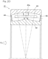
- the bearing for supporting the main shaft is a double-row self-aligning roller bearing 41 having an axially symmetrical structure as shown in Fig. 20 , among rollers 44, 45 in two rows interposed between an inner ring 42 and an outer ring 43, only the rollers 45 in one of the rows that is situated on the rear side with respect to an axial load Fa mainly receive the axial load Fa.
- the rollers 45 in the one row receive both radial load and axial load, while the rollers 44 in the other row receive substantially only the radial load.
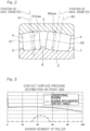
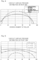
- the rollers 45 in the row that receives the radial load and axial load have higher contact surface pressures than those of the rollers 44 in the row that receives only the radial load, and thus the rolling surfaces of the rollers 45 and the raceway surface 43a of the outer ring 43 are more susceptible to surface damage or wear.
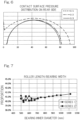
- the rollers 45 in the one row have shorter rolling fatigue life than that of the rollers 44 in the other row. Therefore, the substantial service life of the entire bearing is limited by the shorter rolling life of the rollers 45 in the row that receives the axial load.
- the rollers in the other row are arranged at a larger contact angle than that of the rollers in the one row so that the rollers in the other row can support a larger axial load.
- the rollers having the larger contact angle support substantially all the axial load and a part of the radial load, and the rollers having the smaller contact angle support the rest of the radial load.
- the retainer inclination angle ⁇ 2 may be suitably adjusted such that the pocket surfaces of the retainer can hold the rollers at maximum diameter positions of the rollers.
- rollers in the other row having a larger contact angle can serve as the rollers in the row that receives the axial load
- the rollers in the one row having a smaller contact angle can serve as the rollers in the row that receives substantially only the radial load, so as to suitably share loads between the rollers in the respective rows to accommodate either of fatigue loads and extreme load.
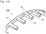
- the rollers 4, 5 in the respective left and right rows are retained by retainers 10L, 10R, respectively.
- the retainer 10L for the left row includes an annular portion 11 and a plurality of pillar portions 12 extending from the annular portion 11 toward the left side, and the rollers 4 in the left row are retained in pockets between the respective pillar portions 12.
- the retainer 10R for the right row includes an annular portion 11 and a plurality of pillar portions 12 extending from the annular portion 11 toward the right side, and the rollers 5 in the right row are retained in pockets between the respective pillar portions 12.
- the rollers 4, 5 in the respective left and right rows are asymmetrical rollers having respective maximum diameters D1max, D2max at positions displaced from centers A1, A2 of the roller lengths thereof.
- the maximum diameter D1max of the rollers 4 in the left row is located to the right of the center A1 of the roller length
- the maximum diameter D2max of the rollers 5 in the right row is located to the left of the center A2 of the roller length.
- Induced thrust loads are generated to the rollers 4, 5 in the left and right rows, which are in the form of such asymmetrical rollers.
- the intermediate flange 8 of the inner ring 2 is provided for receiving the induced thrust loads.
- a combination of the asymmetrical rollers 4, 5 and the intermediate flange 8 allows the rollers 4, 5 to be guided accurately because the rollers 4, 5 are guided at three locations, i.e. the inner ring 2, the outer ring 3 and the intermediate flange 8.
- the assumed axial load and radial load refer to an axial load and a radial load that are fatigue loads when an average wind turbine generator in view of conditions such as its power generation capacity and installation location is most normally operated. Therefore, it is conceivable that an optimum ratio of the contact angles may not be 1:3 in a double-row self-aligning roller bearing in the case where the double-row self-aligning roller bearing is used in a wind turbine generator that is different from such an average wind turbine generator in these conditions. However, even in such a case, the optimum ratio of the contact angles falls within a range of 1:4 to 1:2.
- Fig. 10 and Fig. 11 show another embodiment according to the present invention. This embodiment is the same as the first embodiment, except for the features specifically described below.
- the "inclination angle ⁇ 2 of the retainer 10R” refers to an angle formed between e.g. a retainer center line (bearing center axis O) and a center line C2 of a cylindrical surface defined by each pocket surface 12a between pillar portions 12 of the retainer 10R.
- the "inclination angle ⁇ 2 of the retainer” may alternatively be an inclination angle of an outer diameter surface of the retainer 10R or an inclination angle of an inner diameter surface of the retainer 10R.
- the base material of each of the rollers 4, 5 has a surface roughness expressed by an arithmetic roughness Ra ⁇ 0.3 and a root-mean-square gradient R ⁇ q ⁇ 0.05 on an outer surface of the base material.
- Fig. 11 is a schematic sectional view illustrating the structure of the DLC coating 9.
- the DLC coating 9 has a three-layered structure including: (1) a base layer 9a directly formed on a surface of each roller 4, 5 and mainly containing Cr and WC; (2) a mixed layer 9b formed on the base layer 9a and mainly containing WC and DLC; and (3) a surface layer 9c formed on the mixed layer 9b and mainly containing DLC.
- the mixed layer 9b is formed such that the content of WC in the mixed layer is continuously or stepwisely decreases from the base layer 9a side to the surface layer 9c side, while the content of DLC in the mixed layer continuously or stepwisely increases.
- the DLC coating 9 employs the above-described three-layered structure as its film structure so as to avoid sharp change in physical properties (hardness, elastic modulus).
- the mixed layer 9b is an intermediate layer interposed between the base layer and the surface layer.
- WC used in the mixed layer 9b has a hardness and an elastic modulus intermediate between those of Cr and DLC and hardly causes residual stress concentration after film formation.
- the mixed layer 9b has a gradient composition having a decreasing content of WC and an increasing content of DLC from the base layer 9a side to the surface layer 9c side so that the mixed layer has excellent adhesion on the both surfaces facing the base layer 9a and the surface layer 9c.
- WC and DLC are physically bonded in the mixed layer so that breakage in the mixed layer can be prevented.
- the higher content of DLC on the surface layer 9c side contributes to excellent adhesion between the surface layer 9c and the mixed layer 9b.
- the mixed layer 9b is a layer which serves to bond highly non-adhesive DLC to the base layer 9a side by the presence of WC due to the anchor effect.
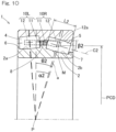
- the inner diameter Di of the annular portion 11 is, for example, PCD ⁇ 95 to 98%.
- the pillar portions 12 are formed with the tapered portions 13 and the cylindrical pocket surfaces 12a are inclined with respect to the axial direction in which the pillar portions 12 extend, so that each pillar portions has a narrowest width W1 at the distal-most end of the pillar portion 12 and is narrower than a width W2 immediately before the point where the tapered portion 13 starts, when the pillar portion 12 is seen from outside in the retainer radial direction toward the retainer center side as shown in Fig. 16 . Also, the pillar portion 12 has a tip end face 12e having a small radial thickness d ( Fig. 17 ).
- the retainers 10L, 10R may be made of bearing steel or any other ferrous material, or a brass-based material.
- tapered portions 13 are formed so as to eliminate the unnecessary portions and thus do not influence retainment of the rollers 5 and because they achieve weight reduction.
Landscapes
- Engineering & Computer Science (AREA)
- General Engineering & Computer Science (AREA)
- Mechanical Engineering (AREA)
- Life Sciences & Earth Sciences (AREA)
- Sustainable Development (AREA)
- Sustainable Energy (AREA)
- Chemical & Material Sciences (AREA)
- Combustion & Propulsion (AREA)
- Rolling Contact Bearings (AREA)
- Wind Motors (AREA)
- Support Of The Bearing (AREA)
Claims (5)
- Roulement à rouleaux à alignement automatique à double rangée comprenant :une bague intérieure ;une bague extérieure ayant une surface de chemin de roulement sphérique ; etune pluralité de rouleaux disposée en deux rangées dans une direction de largeur du roulement et interposée entre la bague intérieure et la bague extérieure, chacun des rouleaux dans les deux rangées ayant une surface périphérique extérieure ayant une forme de section transversale qui correspond à la surface de chemin de roulement de la bague extérieure, dans lequeldans lequel un rapport d'un angle de contact θ1 des rouleaux dans une des rangées par rapport à un angle de contact θ2 des rouleaux dans l'autre des rangées tombe dans une plage de 0,25 ≤ θ1/θ2 ≤ 0,5,caractérisé en cequ'un rapport d'une distance B1 dans la direction de largeur du roulement à partir d'une face d'extrémité du roulement d'un côté de l'une des rangées à une intersection de deux lignes d'action qui définissent les angles de contact des deux rangées par rapport à une distance B2 dans la direction de largeur du roulement à partir d'une face d'extrémité du roulement d'un côté de l'autre des rangées à l'intersection tombe dans une plage de 0,5 ≤ B1/B2 ≤ 0,6.
- Roulement à rouleaux à alignement automatique à double rangée selon la revendication 1, dans lequel un rapport d'une longueur L1 des rouleaux dans l'une des rangées à une longueur L2 des rouleaux dans l'autre des rangées tombe dans une plage de 0,9 ≤ L1/L2 ≤ 1,0.
- Roulement à rouleaux à alignement automatique à double rangée selon la revendication 1 ou 2, dans lequel un angle d'inclinaison β2 d'un élément de retenue qui retient les rouleaux dans l'autre des rangées a une relation par rapport à un angle α2 du diamètre maximal du rouleau qui est un angle d'inclinaison des rouleaux dans l'autre des rangées à un point où chacun des rouleaux dans l'autre des rangées a un diamètre maximal, la relation étant exprimée par une inéquation : 0 ≤ β2 ≤ α2.
- Roulement à rouleaux à alignement automatique à double rangée selon l'une quelconque des revendications 1 à 3, dans lequel chacun des rouleaux a une surface périphérique extérieure qui est revêtue d'un revêtement de CDA ayant une structure multicouche ;le revêtement de CDA ayant une épaisseur de feuil de 2,0 µm ou supérieur ;un matériau de base de chacun des rouleaux ayant une rugosité de surface de Ra ≤ 0,3 et un gradient moyen quadratique RΔq ≤ 0,05 sur une surface extérieure du matériau de base ; etle revêtement de CDA ayant la structure multicouche comprenant des couches dont chacune a une dureté de feuil, la dureté de feuil augmentant graduellement vers la couche du côté extérieur.
- Roulement à rouleaux à alignement automatique à double rangée selon l'une quelconque des revendications 1 à 4, dans lequel le roulement à rouleaux à alignement automatique à double rangée est utilisé pour supporter un arbre principal d'un générateur éolien.
Applications Claiming Priority (3)
| Application Number | Priority Date | Filing Date | Title |
|---|---|---|---|
| JP2018081203 | 2018-04-20 | ||
| JP2019072707A JP7488633B2 (ja) | 2018-04-20 | 2019-04-05 | 複列自動調心ころ軸受 |
| PCT/JP2019/016453 WO2019203265A1 (fr) | 2018-04-20 | 2019-04-17 | Roulement à rouleaux à alignement automatique à double rangée |
Publications (3)
| Publication Number | Publication Date |
|---|---|
| EP3783237A1 EP3783237A1 (fr) | 2021-02-24 |
| EP3783237A4 EP3783237A4 (fr) | 2021-12-22 |
| EP3783237B1 true EP3783237B1 (fr) | 2023-10-11 |
Family
ID=68388976
Family Applications (1)
| Application Number | Title | Priority Date | Filing Date |
|---|---|---|---|
| EP19788217.8A Active EP3783237B1 (fr) | 2018-04-20 | 2019-04-17 | Roulement à rouleaux à alignement automatique à double rangée |
Country Status (2)
| Country | Link |
|---|---|
| EP (1) | EP3783237B1 (fr) |
| JP (1) | JP7488633B2 (fr) |
Families Citing this family (1)
| Publication number | Priority date | Publication date | Assignee | Title |
|---|---|---|---|---|
| AT524591B1 (de) | 2021-05-14 | 2022-07-15 | Miba Gleitlager Austria Gmbh | Gondel für eine Windkraftanlage |
Family Cites Families (5)
| Publication number | Priority date | Publication date | Assignee | Title |
|---|---|---|---|---|
| JP5620860B2 (ja) * | 2010-03-30 | 2014-11-05 | Ntn株式会社 | 転がり軸受 |
| US9051653B2 (en) * | 2010-03-30 | 2015-06-09 | Ntn Corporation | Rolling bearing |
| DE102015204970A1 (de) * | 2015-03-19 | 2016-09-22 | Schaeffler Technologies AG & Co. KG | Wälzlager, beispielsweise einer Windkraftanlage |
| JP2016186355A (ja) * | 2015-03-27 | 2016-10-27 | Ntn株式会社 | 転がり軸受用保持器および転がり軸受 |
| WO2017164325A1 (fr) * | 2016-03-24 | 2017-09-28 | Ntn株式会社 | Palier à rouleaux sphérique à double rangée |
-
2019
- 2019-04-05 JP JP2019072707A patent/JP7488633B2/ja active Active
- 2019-04-17 EP EP19788217.8A patent/EP3783237B1/fr active Active
Also Published As
| Publication number | Publication date |
|---|---|
| JP2019190658A (ja) | 2019-10-31 |
| EP3783237A1 (fr) | 2021-02-24 |
| EP3783237A4 (fr) | 2021-12-22 |
| JP7488633B2 (ja) | 2024-05-22 |
Similar Documents
| Publication | Publication Date | Title |
|---|---|---|
| EP1673553B1 (fr) | Train d'engrenages planetaire | |
| EP3434918B1 (fr) | Palier à rouleaux sphérique auto-alignés à double rangée | |
| US7918649B2 (en) | Double-row self-aligning roller bearing and device for supporting wind turbine generator main shaft | |
| US11306776B2 (en) | Double-row self-aligning roller bearing | |
| WO2017164325A1 (fr) | Palier à rouleaux sphérique à double rangée | |
| US11773901B2 (en) | Self-aligning roller bearing | |
| US10697492B2 (en) | Double-row self-aligning roller bearing | |
| EP3783237B1 (fr) | Roulement à rouleaux à alignement automatique à double rangée | |
| US11187266B2 (en) | Double-row self-aligning roller bearing | |
| JP2006189133A (ja) | スラストころ軸受 | |
| JP2005155838A (ja) | ころ軸受 | |
| CN118234964A (zh) | 机械滚柱轴承 | |
| JP2006112560A (ja) | 円すいころ軸受 |
Legal Events
| Date | Code | Title | Description |
|---|---|---|---|
| STAA | Information on the status of an ep patent application or granted ep patent |
Free format text: STATUS: THE INTERNATIONAL PUBLICATION HAS BEEN MADE |
|
| PUAI | Public reference made under article 153(3) epc to a published international application that has entered the european phase |
Free format text: ORIGINAL CODE: 0009012 |
|
| STAA | Information on the status of an ep patent application or granted ep patent |
Free format text: STATUS: REQUEST FOR EXAMINATION WAS MADE |
|
| 17P | Request for examination filed |
Effective date: 20201103 |
|
| AK | Designated contracting states |
Kind code of ref document: A1 Designated state(s): AL AT BE BG CH CY CZ DE DK EE ES FI FR GB GR HR HU IE IS IT LI LT LU LV MC MK MT NL NO PL PT RO RS SE SI SK SM TR |
|
| AX | Request for extension of the european patent |
Extension state: BA ME |
|
| DAV | Request for validation of the european patent (deleted) | ||
| DAX | Request for extension of the european patent (deleted) | ||
| A4 | Supplementary search report drawn up and despatched |
Effective date: 20211118 |
|
| RIC1 | Information provided on ipc code assigned before grant |
Ipc: F16C 19/38 20060101ALI20211112BHEP Ipc: F03D 80/70 20160101ALI20211112BHEP Ipc: F16C 23/08 20060101AFI20211112BHEP |
|
| GRAP | Despatch of communication of intention to grant a patent |
Free format text: ORIGINAL CODE: EPIDOSNIGR1 |
|
| STAA | Information on the status of an ep patent application or granted ep patent |
Free format text: STATUS: GRANT OF PATENT IS INTENDED |
|
| INTG | Intention to grant announced |
Effective date: 20230426 |
|
| GRAS | Grant fee paid |
Free format text: ORIGINAL CODE: EPIDOSNIGR3 |
|
| GRAA | (expected) grant |
Free format text: ORIGINAL CODE: 0009210 |
|
| STAA | Information on the status of an ep patent application or granted ep patent |
Free format text: STATUS: THE PATENT HAS BEEN GRANTED |
|
| AK | Designated contracting states |
Kind code of ref document: B1 Designated state(s): AL AT BE BG CH CY CZ DE DK EE ES FI FR GB GR HR HU IE IS IT LI LT LU LV MC MK MT NL NO PL PT RO RS SE SI SK SM TR |
|
| REG | Reference to a national code |
Ref country code: GB Ref legal event code: FG4D |
|
| REG | Reference to a national code |
Ref country code: CH Ref legal event code: EP |
|
| REG | Reference to a national code |
Ref country code: DE Ref legal event code: R096 Ref document number: 602019039226 Country of ref document: DE |
|
| REG | Reference to a national code |
Ref country code: IE Ref legal event code: FG4D |
|
| REG | Reference to a national code |
Ref country code: DK Ref legal event code: T3 Effective date: 20240104 |
|
| REG | Reference to a national code |
Ref country code: LT Ref legal event code: MG9D |
|
| REG | Reference to a national code |
Ref country code: NL Ref legal event code: MP Effective date: 20231011 |
|
| REG | Reference to a national code |
Ref country code: AT Ref legal event code: MK05 Ref document number: 1620490 Country of ref document: AT Kind code of ref document: T Effective date: 20231011 |
|
| PG25 | Lapsed in a contracting state [announced via postgrant information from national office to epo] |
Ref country code: NL Free format text: LAPSE BECAUSE OF FAILURE TO SUBMIT A TRANSLATION OF THE DESCRIPTION OR TO PAY THE FEE WITHIN THE PRESCRIBED TIME-LIMIT Effective date: 20231011 |
|
| PG25 | Lapsed in a contracting state [announced via postgrant information from national office to epo] |
Ref country code: GR Free format text: LAPSE BECAUSE OF FAILURE TO SUBMIT A TRANSLATION OF THE DESCRIPTION OR TO PAY THE FEE WITHIN THE PRESCRIBED TIME-LIMIT Effective date: 20240112 |
|
| PG25 | Lapsed in a contracting state [announced via postgrant information from national office to epo] |
Ref country code: IS Free format text: LAPSE BECAUSE OF FAILURE TO SUBMIT A TRANSLATION OF THE DESCRIPTION OR TO PAY THE FEE WITHIN THE PRESCRIBED TIME-LIMIT Effective date: 20240211 |
|
| PG25 | Lapsed in a contracting state [announced via postgrant information from national office to epo] |
Ref country code: LT Free format text: LAPSE BECAUSE OF FAILURE TO SUBMIT A TRANSLATION OF THE DESCRIPTION OR TO PAY THE FEE WITHIN THE PRESCRIBED TIME-LIMIT Effective date: 20231011 |
|
| PG25 | Lapsed in a contracting state [announced via postgrant information from national office to epo] |
Ref country code: AT Free format text: LAPSE BECAUSE OF FAILURE TO SUBMIT A TRANSLATION OF THE DESCRIPTION OR TO PAY THE FEE WITHIN THE PRESCRIBED TIME-LIMIT Effective date: 20231011 |
|
| PG25 | Lapsed in a contracting state [announced via postgrant information from national office to epo] |
Ref country code: ES Free format text: LAPSE BECAUSE OF FAILURE TO SUBMIT A TRANSLATION OF THE DESCRIPTION OR TO PAY THE FEE WITHIN THE PRESCRIBED TIME-LIMIT Effective date: 20231011 |
|
| PG25 | Lapsed in a contracting state [announced via postgrant information from national office to epo] |
Ref country code: LT Free format text: LAPSE BECAUSE OF FAILURE TO SUBMIT A TRANSLATION OF THE DESCRIPTION OR TO PAY THE FEE WITHIN THE PRESCRIBED TIME-LIMIT Effective date: 20231011 Ref country code: IS Free format text: LAPSE BECAUSE OF FAILURE TO SUBMIT A TRANSLATION OF THE DESCRIPTION OR TO PAY THE FEE WITHIN THE PRESCRIBED TIME-LIMIT Effective date: 20240211 Ref country code: GR Free format text: LAPSE BECAUSE OF FAILURE TO SUBMIT A TRANSLATION OF THE DESCRIPTION OR TO PAY THE FEE WITHIN THE PRESCRIBED TIME-LIMIT Effective date: 20240112 Ref country code: ES Free format text: LAPSE BECAUSE OF FAILURE TO SUBMIT A TRANSLATION OF THE DESCRIPTION OR TO PAY THE FEE WITHIN THE PRESCRIBED TIME-LIMIT Effective date: 20231011 Ref country code: BG Free format text: LAPSE BECAUSE OF FAILURE TO SUBMIT A TRANSLATION OF THE DESCRIPTION OR TO PAY THE FEE WITHIN THE PRESCRIBED TIME-LIMIT Effective date: 20240111 Ref country code: AT Free format text: LAPSE BECAUSE OF FAILURE TO SUBMIT A TRANSLATION OF THE DESCRIPTION OR TO PAY THE FEE WITHIN THE PRESCRIBED TIME-LIMIT Effective date: 20231011 Ref country code: PT Free format text: LAPSE BECAUSE OF FAILURE TO SUBMIT A TRANSLATION OF THE DESCRIPTION OR TO PAY THE FEE WITHIN THE PRESCRIBED TIME-LIMIT Effective date: 20240212 |
|
| PG25 | Lapsed in a contracting state [announced via postgrant information from national office to epo] |
Ref country code: SE Free format text: LAPSE BECAUSE OF FAILURE TO SUBMIT A TRANSLATION OF THE DESCRIPTION OR TO PAY THE FEE WITHIN THE PRESCRIBED TIME-LIMIT Effective date: 20231011 Ref country code: RS Free format text: LAPSE BECAUSE OF FAILURE TO SUBMIT A TRANSLATION OF THE DESCRIPTION OR TO PAY THE FEE WITHIN THE PRESCRIBED TIME-LIMIT Effective date: 20231011 Ref country code: PL Free format text: LAPSE BECAUSE OF FAILURE TO SUBMIT A TRANSLATION OF THE DESCRIPTION OR TO PAY THE FEE WITHIN THE PRESCRIBED TIME-LIMIT Effective date: 20231011 Ref country code: NO Free format text: LAPSE BECAUSE OF FAILURE TO SUBMIT A TRANSLATION OF THE DESCRIPTION OR TO PAY THE FEE WITHIN THE PRESCRIBED TIME-LIMIT Effective date: 20240111 Ref country code: LV Free format text: LAPSE BECAUSE OF FAILURE TO SUBMIT A TRANSLATION OF THE DESCRIPTION OR TO PAY THE FEE WITHIN THE PRESCRIBED TIME-LIMIT Effective date: 20231011 Ref country code: HR Free format text: LAPSE BECAUSE OF FAILURE TO SUBMIT A TRANSLATION OF THE DESCRIPTION OR TO PAY THE FEE WITHIN THE PRESCRIBED TIME-LIMIT Effective date: 20231011 |
|
| PGFP | Annual fee paid to national office [announced via postgrant information from national office to epo] |
Ref country code: DE Payment date: 20240313 Year of fee payment: 6 |
|
| PGFP | Annual fee paid to national office [announced via postgrant information from national office to epo] |
Ref country code: DK Payment date: 20240411 Year of fee payment: 6 |
|
| REG | Reference to a national code |
Ref country code: DE Ref legal event code: R097 Ref document number: 602019039226 Country of ref document: DE |
|
| PG25 | Lapsed in a contracting state [announced via postgrant information from national office to epo] |
Ref country code: CZ Free format text: LAPSE BECAUSE OF FAILURE TO SUBMIT A TRANSLATION OF THE DESCRIPTION OR TO PAY THE FEE WITHIN THE PRESCRIBED TIME-LIMIT Effective date: 20231011 |
|
| PG25 | Lapsed in a contracting state [announced via postgrant information from national office to epo] |
Ref country code: SK Free format text: LAPSE BECAUSE OF FAILURE TO SUBMIT A TRANSLATION OF THE DESCRIPTION OR TO PAY THE FEE WITHIN THE PRESCRIBED TIME-LIMIT Effective date: 20231011 |
|
| PG25 | Lapsed in a contracting state [announced via postgrant information from national office to epo] |
Ref country code: SM Free format text: LAPSE BECAUSE OF FAILURE TO SUBMIT A TRANSLATION OF THE DESCRIPTION OR TO PAY THE FEE WITHIN THE PRESCRIBED TIME-LIMIT Effective date: 20231011 Ref country code: SK Free format text: LAPSE BECAUSE OF FAILURE TO SUBMIT A TRANSLATION OF THE DESCRIPTION OR TO PAY THE FEE WITHIN THE PRESCRIBED TIME-LIMIT Effective date: 20231011 Ref country code: RO Free format text: LAPSE BECAUSE OF FAILURE TO SUBMIT A TRANSLATION OF THE DESCRIPTION OR TO PAY THE FEE WITHIN THE PRESCRIBED TIME-LIMIT Effective date: 20231011 Ref country code: IT Free format text: LAPSE BECAUSE OF FAILURE TO SUBMIT A TRANSLATION OF THE DESCRIPTION OR TO PAY THE FEE WITHIN THE PRESCRIBED TIME-LIMIT Effective date: 20231011 Ref country code: EE Free format text: LAPSE BECAUSE OF FAILURE TO SUBMIT A TRANSLATION OF THE DESCRIPTION OR TO PAY THE FEE WITHIN THE PRESCRIBED TIME-LIMIT Effective date: 20231011 Ref country code: CZ Free format text: LAPSE BECAUSE OF FAILURE TO SUBMIT A TRANSLATION OF THE DESCRIPTION OR TO PAY THE FEE WITHIN THE PRESCRIBED TIME-LIMIT Effective date: 20231011 |
|
| PLBE | No opposition filed within time limit |
Free format text: ORIGINAL CODE: 0009261 |
|
| STAA | Information on the status of an ep patent application or granted ep patent |
Free format text: STATUS: NO OPPOSITION FILED WITHIN TIME LIMIT |
|
| 26N | No opposition filed |
Effective date: 20240712 |