WO2019202856A1 - 電子血圧計および心不全検出器 - Google Patents
電子血圧計および心不全検出器 Download PDFInfo
- Publication number
- WO2019202856A1 WO2019202856A1 PCT/JP2019/007725 JP2019007725W WO2019202856A1 WO 2019202856 A1 WO2019202856 A1 WO 2019202856A1 JP 2019007725 W JP2019007725 W JP 2019007725W WO 2019202856 A1 WO2019202856 A1 WO 2019202856A1
- Authority
- WO
- WIPO (PCT)
- Prior art keywords
- blood pressure
- pulse wave
- heart failure
- envelope
- pressure
- Prior art date
- Legal status (The legal status is an assumption and is not a legal conclusion. Google has not performed a legal analysis and makes no representation as to the accuracy of the status listed.)
- Ceased
Links
Images


Classifications
-
- A—HUMAN NECESSITIES
- A61—MEDICAL OR VETERINARY SCIENCE; HYGIENE
- A61B—DIAGNOSIS; SURGERY; IDENTIFICATION
- A61B5/00—Measuring for diagnostic purposes; Identification of persons
- A61B5/02—Detecting, measuring or recording for evaluating the cardiovascular system, e.g. pulse, heart rate, blood pressure or blood flow
- A61B5/021—Measuring pressure in heart or blood vessels
- A61B5/022—Measuring pressure in heart or blood vessels by applying pressure to close blood vessels, e.g. against the skin; Ophthalmodynamometers
- A61B5/0225—Measuring pressure in heart or blood vessels by applying pressure to close blood vessels, e.g. against the skin; Ophthalmodynamometers the pressure being controlled by electric signals, e.g. derived from Korotkoff sounds
-
- A—HUMAN NECESSITIES
- A61—MEDICAL OR VETERINARY SCIENCE; HYGIENE
- A61B—DIAGNOSIS; SURGERY; IDENTIFICATION
- A61B5/00—Measuring for diagnostic purposes; Identification of persons
- A61B5/02—Detecting, measuring or recording for evaluating the cardiovascular system, e.g. pulse, heart rate, blood pressure or blood flow
- A61B5/021—Measuring pressure in heart or blood vessels
- A61B5/022—Measuring pressure in heart or blood vessels by applying pressure to close blood vessels, e.g. against the skin; Ophthalmodynamometers
- A61B5/02225—Measuring pressure in heart or blood vessels by applying pressure to close blood vessels, e.g. against the skin; Ophthalmodynamometers using the oscillometric method
-
- A—HUMAN NECESSITIES
- A61—MEDICAL OR VETERINARY SCIENCE; HYGIENE
- A61B—DIAGNOSIS; SURGERY; IDENTIFICATION
- A61B10/00—Instruments for taking body samples for diagnostic purposes; Other methods or instruments for diagnosis, e.g. for vaccination diagnosis, sex determination or ovulation-period determination; Throat striking implements
-
- A—HUMAN NECESSITIES
- A61—MEDICAL OR VETERINARY SCIENCE; HYGIENE
- A61B—DIAGNOSIS; SURGERY; IDENTIFICATION
- A61B5/00—Measuring for diagnostic purposes; Identification of persons
- A61B5/72—Signal processing specially adapted for physiological signals or for diagnostic purposes
- A61B5/7235—Details of waveform analysis
- A61B5/7246—Details of waveform analysis using correlation, e.g. template matching or determination of similarity
-
- A—HUMAN NECESSITIES
- A61—MEDICAL OR VETERINARY SCIENCE; HYGIENE
- A61B—DIAGNOSIS; SURGERY; IDENTIFICATION
- A61B5/00—Measuring for diagnostic purposes; Identification of persons
- A61B5/72—Signal processing specially adapted for physiological signals or for diagnostic purposes
- A61B5/7271—Specific aspects of physiological measurement analysis
- A61B5/7275—Determining trends in physiological measurement data; Predicting development of a medical condition based on physiological measurements, e.g. determining a risk factor
-
- A—HUMAN NECESSITIES
- A61—MEDICAL OR VETERINARY SCIENCE; HYGIENE
- A61B—DIAGNOSIS; SURGERY; IDENTIFICATION
- A61B5/00—Measuring for diagnostic purposes; Identification of persons
- A61B5/72—Signal processing specially adapted for physiological signals or for diagnostic purposes
- A61B5/7271—Specific aspects of physiological measurement analysis
- A61B5/7278—Artificial waveform generation or derivation, e.g. synthesizing signals from measured signals
-
- A—HUMAN NECESSITIES
- A61—MEDICAL OR VETERINARY SCIENCE; HYGIENE
- A61B—DIAGNOSIS; SURGERY; IDENTIFICATION
- A61B5/00—Measuring for diagnostic purposes; Identification of persons
- A61B5/72—Signal processing specially adapted for physiological signals or for diagnostic purposes
- A61B5/7271—Specific aspects of physiological measurement analysis
- A61B5/7282—Event detection, e.g. detecting unique waveforms indicative of a medical condition
-
- A—HUMAN NECESSITIES
- A61—MEDICAL OR VETERINARY SCIENCE; HYGIENE
- A61B—DIAGNOSIS; SURGERY; IDENTIFICATION
- A61B5/00—Measuring for diagnostic purposes; Identification of persons
- A61B5/72—Signal processing specially adapted for physiological signals or for diagnostic purposes
- A61B5/7271—Specific aspects of physiological measurement analysis
- A61B5/7285—Specific aspects of physiological measurement analysis for synchronizing or triggering a physiological measurement or image acquisition with a physiological event or waveform, e.g. an ECG signal
-
- A—HUMAN NECESSITIES
- A61—MEDICAL OR VETERINARY SCIENCE; HYGIENE
- A61B—DIAGNOSIS; SURGERY; IDENTIFICATION
- A61B5/00—Measuring for diagnostic purposes; Identification of persons
- A61B5/74—Details of notification to user or communication with user or patient; User input means
- A61B5/742—Details of notification to user or communication with user or patient; User input means using visual displays
- A61B5/7425—Displaying combinations of multiple images regardless of image source, e.g. displaying a reference anatomical image with a live image
-
- A—HUMAN NECESSITIES
- A61—MEDICAL OR VETERINARY SCIENCE; HYGIENE
- A61B—DIAGNOSIS; SURGERY; IDENTIFICATION
- A61B5/00—Measuring for diagnostic purposes; Identification of persons
- A61B5/74—Details of notification to user or communication with user or patient; User input means
- A61B5/746—Alarms related to a physiological condition, e.g. details of setting alarm thresholds or avoiding false alarms
-
- H—ELECTRICITY
- H04—ELECTRIC COMMUNICATION TECHNIQUE
- H04L—TRANSMISSION OF DIGITAL INFORMATION, e.g. TELEGRAPHIC COMMUNICATION
- H04L67/00—Network arrangements or protocols for supporting network services or applications
- H04L67/01—Protocols
- H04L67/12—Protocols specially adapted for proprietary or special-purpose networking environments, e.g. medical networks, sensor networks, networks in vehicles or remote metering networks
-
- A—HUMAN NECESSITIES
- A61—MEDICAL OR VETERINARY SCIENCE; HYGIENE
- A61B—DIAGNOSIS; SURGERY; IDENTIFICATION
- A61B5/00—Measuring for diagnostic purposes; Identification of persons
- A61B5/02—Detecting, measuring or recording for evaluating the cardiovascular system, e.g. pulse, heart rate, blood pressure or blood flow
- A61B5/021—Measuring pressure in heart or blood vessels
- A61B5/022—Measuring pressure in heart or blood vessels by applying pressure to close blood vessels, e.g. against the skin; Ophthalmodynamometers
- A61B5/02233—Occluders specially adapted therefor
-
- A—HUMAN NECESSITIES
- A61—MEDICAL OR VETERINARY SCIENCE; HYGIENE
- A61B—DIAGNOSIS; SURGERY; IDENTIFICATION
- A61B5/00—Measuring for diagnostic purposes; Identification of persons
- A61B5/02—Detecting, measuring or recording for evaluating the cardiovascular system, e.g. pulse, heart rate, blood pressure or blood flow
- A61B5/024—Measuring pulse rate or heart rate
- A61B5/0245—Measuring pulse rate or heart rate by using sensing means generating electric signals, i.e. ECG signals
- A61B5/025—Measuring pulse rate or heart rate by using sensing means generating electric signals, i.e. ECG signals within occluders, e.g. responsive to Korotkoff sounds
-
- A—HUMAN NECESSITIES
- A61—MEDICAL OR VETERINARY SCIENCE; HYGIENE
- A61B—DIAGNOSIS; SURGERY; IDENTIFICATION
- A61B5/00—Measuring for diagnostic purposes; Identification of persons
- A61B5/08—Measuring devices for evaluating the respiratory organs
Definitions
- the present invention relates to an electronic sphygmomanometer, and more particularly to an electronic sphygmomanometer that measures the blood pressure of a measurement site by an oscillometric method.
- the present invention also relates to a heart failure detector that outputs an index that relatively represents the severity of heart failure.
- Non-Patent Document 1 As a device for monitoring the state of heart failure at home, for example, Non-Patent Document 1 (Ishimaru et al., “An example of heart failure that was able to be detected early and handled by OptiVol TM ”, Heart, 45 (3), PP .321-326, 2013), OptiVol (registered trademark) (manufactured by Medtronic) that measures impedance in the thorax is known.
- This device is configured to detect a state in which congestion has occurred in the lungs due to a decrease in the pump function of the heart by changing its impedance.
- an electronic sphygmomanometer that measures the blood pressure of a measurement site by an oscillometric method is non-invasive to a subject, and thus can be easily used even by a general person other than a doctor.
- an object of the present invention is an electronic sphygmomanometer that measures the blood pressure of a measurement site by an oscillometric method, and is an index that is non-invasive to a subject and relatively represents the severity of heart failure (hereinafter referred to as “heart failure index”.
- Another object of the present invention is to provide a heart failure detector that can output such a heart failure index non-invasively to a subject.
- the present inventor has focused on the possibility that there is a correlation between blood pressure fluctuation synchronized with breathing (respiratory fluctuation) and the severity of heart failure.
- Non-Patent Document 2 (Azriel Perel et al., “Fluctuation in systolic blood pressure is a sensitive indicator of blood volume reduction in ventilated dogs undergoing graded bleeding” (Systolic Blood pressure Variation is a According to Sensitive Indicator of Hypovolemia in Ventilated Dogs Subjected to Graded Hemorrhage), Anesthesiology, 67, PP.498-502, 1987), systolic pressure variation (SPV) and its ⁇ down The ingredient has been reported to be an accurate indicator of blood volume loss in ventilated dogs that have undergone bleeding.
- the systolic blood pressure fluctuation (SPV) in the same document is defined as the difference between the maximum value and the minimum value of the systolic blood pressure following a single positive pressure breath. Therefore, the systolic blood pressure fluctuation (SPV) in the document is considered to correspond to the “respiratory fluctuation” of blood pressure in the present specification.
- SPV systolic blood pressure fluctuation
- heart failure is a condition in which the function of the heart pump is reduced, and it is impossible to pump out enough blood to the whole body or to receive enough blood around the whole body. Is considered to correspond to the severity of heart failure.
- an electronic sphygmomanometer is a blood pressure fluctuation amount synchronized with respiration when measuring blood pressure non-invasively according to an oscillometric method. What calculates
- the present inventor obtains a blood pressure fluctuation amount (respiratory fluctuation) synchronized with respiration by an electronic sphygmomanometer that measures the blood pressure of the measurement site by an oscillometric method, and the severity of heart failure depends on the blood pressure fluctuation amount.
- the idea was to find a heart failure index that relatively represents the degree.
- an electronic sphygmomanometer of this disclosure is An electronic sphygmomanometer that measures the blood pressure of a measurement site by an oscillometric method, A cuff pressure control unit capable of changing the pressure of the cuff attached to the measurement site; A pressure detector for detecting a cuff pressure signal representing the pressure of the cuff; Based on the cuff pressure signal, a fluctuation amount calculation unit for obtaining a blood pressure fluctuation amount synchronized with respiration, And an index output unit that outputs a numerical value predetermined corresponding to the blood pressure fluctuation amount as a heart failure index relatively representing the severity of heart failure.
- the heart failure index means that the severity of heart failure is “relatively”. The value of the heart failure index is large or small and the heart failure severity is heavy or light (or vice versa, light or heavy. It may correspond to)).
- the cuff pressure control unit changes the pressure of the cuff attached to the measurement site during measurement.
- the pressure detection unit detects a cuff pressure signal representing the cuff pressure. Based on this cuff pressure signal, the blood pressure (systolic blood pressure and diastolic blood pressure) of the measurement site is obtained by the oscillometric method.
- the fluctuation amount calculation unit obtains the blood pressure fluctuation amount synchronized with respiration based on the cuff pressure signal.
- the index output unit outputs a predetermined numerical value corresponding to the blood pressure fluctuation amount as a heart failure index that relatively represents the severity of heart failure.
- the cuff pressure control unit and the pressure detection unit are components included in a general commercially available electronic sphygmomanometer in order to obtain the blood pressure of the measurement site by the oscillometric method, and need to be invasive to the subject. And not.
- the fluctuation amount calculation unit and the index output unit are components that perform computation using the cuff pressure signal and the blood pressure fluctuation amount (a quantity obtained based on the cuff pressure signal), respectively. Does not require invasion. Therefore, this electronic sphygmomanometer can output the heart failure index non-invasively to the subject.
- a user including a subject and a person who takes care of the subject. The same applies hereinafter) can know whether or not the state of heart failure has deteriorated by this heart failure index. If the state of heart failure has deteriorated, appropriate measures can be taken, such as visiting a hospital and receiving a doctor's examination even on a day other than the scheduled examination date.
- the electronic sphygmomanometer includes a correspondence storage unit that stores a predetermined correspondence between the blood pressure fluctuation amount and the heart failure index.
- the index output unit refers to the correspondence relationship stored in advance in the correspondence relationship storage unit, and The above heart failure index corresponding to the blood pressure fluctuation amount is obtained. Thereby, the said heart failure parameter
- the predetermined correspondence relationship between the blood pressure fluctuation amount and the heart failure index may take various forms such as a function and a correspondence table.
- a first envelope creation unit that creates a first envelope connecting the amplitudes of the amplitude sequence acquired by the pulse wave amplitude sequence acquisition unit;
- An extreme point detection unit for detecting a local maximum point and a local minimum point in the first envelope;
- On the plane in which the cuff pressure and the pulse wave amplitude form orthogonal coordinates, among the amplitude columns acquired by the pulse wave amplitude column acquisition unit, the amplitudes corresponding to the maximum points are described.
- a maximal point envelope creating unit that creates a maximal point envelope connecting On the plane, among the amplitude columns acquired by the pulse wave amplitude sequence acquisition unit, for the amplitude column corresponding to the minimum point, a minimum point that creates a minimum point envelope connecting those amplitudes
- the fluctuation amount calculation unit calculates a first difference or ratio between the pulse wave amplitude taken by the maximum point envelope and the pulse wave amplitude taken by the minimum point envelope at a certain cuff pressure on the plane. The blood pressure fluctuation amount is obtained.
- the first envelope, the maximum point envelope, and the minimum point envelope are typically represented on a plane with the cuff pressure as the horizontal axis and the pulse wave amplitude as the vertical axis.
- the pulse wave amplitude string acquisition unit extracts a pulse wave signal representing the pulse wave of the measurement site superimposed on the cuff pressure signal, and has an amplitude indicated by the pulse wave signal. Get the column.
- the first envelope creation unit creates a first envelope that connects the amplitudes of the amplitude sequence acquired by the pulse wave amplitude sequence acquisition unit.
- the extreme point detection unit detects a local maximum point and a local minimum point in the first envelope.
- the maximal point envelope generating unit has an amplitude corresponding to the maximal point in the amplitude sequence acquired by the pulse wave amplitude sequence acquiring unit on a plane in which the cuff pressure and the pulse wave amplitude form orthogonal coordinates.
- the minimum point envelope creation unit is a minimum connecting the amplitudes to the amplitude column corresponding to the minimum point among the amplitude columns acquired by the pulse wave amplitude sequence acquisition unit on the plane.
- the fluctuation amount calculation unit calculates a first difference or ratio between the pulse wave amplitude taken by the maximum point envelope and the pulse wave amplitude taken by the minimum point envelope at a certain cuff pressure on the plane. The blood pressure fluctuation amount is obtained. Thereby, the blood pressure fluctuation amount synchronized with respiration can be actually obtained.
- a plurality of “certain cuff pressures” that give the first difference or ratio may be set.
- statistical processing for example, processing for obtaining an average value
- a first envelope creation unit that creates a first envelope connecting the amplitudes of the amplitude sequence acquired by the pulse wave amplitude sequence acquisition unit;
- An extreme point detection unit for detecting a local maximum point and a local minimum point in the first envelope;
- On the plane in which the cuff pressure and the pulse wave amplitude form orthogonal coordinates, among the amplitude columns acquired by the pulse wave amplitude column acquisition unit, the amplitudes corresponding to the maximum points are described.
- a maximal point envelope creating unit that creates a maximal point envelope connecting On the plane, among the amplitude columns acquired by the pulse wave amplitude sequence acquisition unit, for the amplitude column corresponding to the minimum point, a minimum point that creates a minimum point envelope connecting those amplitudes
- An envelope creation unit is a portion on the higher voltage side than the maximum peak of the maximum point envelope and the minimum point envelope on the plane, or from the maximum peak of the maximum point envelope and the minimum point envelope.
- the second difference or ratio between the cuff pressure taken by the maximum point envelope and the cuff pressure taken by the minimum point envelope at a certain pulse wave amplitude is obtained as the blood pressure fluctuation amount. It is characterized by that.
- the first envelope, the maximum point envelope, and the minimum point envelope typically have the cuff pressure on the horizontal axis and the pulse wave amplitude on the vertical axis. Represented on the graph.
- the pulse wave amplitude string acquisition unit extracts a pulse wave signal representing the pulse wave of the measurement site superimposed on the cuff pressure signal, and has an amplitude indicated by the pulse wave signal. Get the column.
- the first envelope creation unit creates a first envelope that connects the amplitudes of the amplitude sequence acquired by the pulse wave amplitude sequence acquisition unit.
- the extreme point detection unit detects a local maximum point and a local minimum point in the first envelope.
- the maximal point envelope generating unit has an amplitude corresponding to the maximal point in the amplitude sequence acquired by the pulse wave amplitude sequence acquiring unit on a plane in which the cuff pressure and the pulse wave amplitude form orthogonal coordinates.
- the minimum point envelope creation unit is a minimum connecting the amplitudes to the amplitude column corresponding to the minimum point among the amplitude columns acquired by the pulse wave amplitude sequence acquisition unit on the plane.
- the fluctuation amount calculation unit is a portion on the higher voltage side than the maximum peak of the maximum point envelope and the minimum point envelope on the plane, or from the maximum peak of the maximum point envelope and the minimum point envelope.
- the second difference or ratio between the cuff pressure taken by the maximum point envelope and the cuff pressure taken by the minimum point envelope at a certain pulse wave amplitude is obtained as the blood pressure fluctuation amount. . Thereby, the blood pressure fluctuation amount synchronized with respiration can be actually obtained.
- a plurality of “certain pulse wave amplitudes” giving the second difference or ratio may be set.
- statistical processing for example, processing for obtaining an average value
- processing for obtaining an average value is performed on the second difference or ratio obtained in accordance with a plurality of the set pulse wave amplitudes to obtain the blood pressure fluctuation amount.
- the display device includes a display processing unit that performs a process of displaying the heart failure index together with a blood pressure calculation result by an oscillometric method.
- the heart failure index is displayed on the display together with the blood pressure calculation result by the oscillometric method.
- the user including the test subject and the person who takes care of the test subject, etc.
- the user is also able to deteriorate the state of heart failure by viewing the displayed heart failure index together with the blood pressure calculation result by the oscillometric method. You can know if you are.
- the heart failure detector of this disclosure comprises: A heart failure detector that outputs an indicator that relatively represents the severity of heart failure, A cuff pressure control unit capable of changing the pressure of the cuff attached to the measurement site; A pressure detector for detecting a cuff pressure signal representing the pressure of the cuff; Based on the cuff pressure signal, a fluctuation amount calculation unit for obtaining a blood pressure fluctuation amount synchronized with respiration, And an index output unit that outputs a numerical value predetermined corresponding to the blood pressure fluctuation amount as a heart failure index relatively representing the severity of heart failure.
- the heart failure index can be output non-invasively to the subject, like the electronic blood pressure monitor of the previous aspect.
- the user can know whether or not the state of heart failure has deteriorated by this heart failure index. If the state of heart failure has deteriorated, appropriate measures can be taken, such as visiting a hospital and receiving a doctor's examination even on a day other than the scheduled examination date.
- the electronic sphygmomanometer of this disclosure is an electronic sphygmomanometer that measures the blood pressure of a measurement site by an oscillometric method, and is non-invasive to the subject, and the relative severity of heart failure is relatively high.
- a heart failure index can be output.
- the heart failure detector of this disclosure can output the heart failure index non-invasively to the subject, like the electronic blood pressure monitor.
- FIG. 7A is a diagram illustrating a cuff pressure signal detected via the pressure sensor of the electronic sphygmomanometer.
- FIG. 7B is a diagram illustrating a signal (HPF output) extracted from the cuff pressure signal through a high-pass filter.
- FIG. 1 shows the appearance of an electronic sphygmomanometer according to an embodiment of the present invention (the whole is denoted by reference numeral 1 and hereinafter simply referred to as “sphygmomanometer”).
- This sphygmomanometer 1 is for home use, and is for a flexible cuff for connecting a blood pressure measurement cuff 20 attached to an upper arm 90 as a measurement site of a subject, a main body 10, and the cuff 20 and the main body 10. And an air tube 39.
- the cuff 20 contains a fluid bag 22 (see FIG. 2) for pressing the upper arm.
- a display device 50 and an operation unit 52 are provided on the front surface of the main body 10.
- the display device 50 is composed of an LCD (Liquid Crystal Display Element) in this example, and electronically displays related to blood pressure measurement according to a control signal from a CPU (Central Processing Unit) 100 (see FIG. 2) described later.
- LCD Liquid Crystal Display Element
- CPU Central Processing Unit
- the operation unit 52 includes a power switch 52A that receives an input of an instruction for turning on or off the power source of the sphygmomanometer 1, and a measurement / stop switch 52B for receiving an instruction to measure or stop blood pressure. And have. These switches 52 ⁇ / b> A and 52 ⁇ / b> B input an operation signal according to an instruction from the user to the CPU 100.
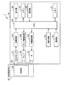
- the main body 10 of the sphygmomanometer 1 includes a memory 51 as a storage unit, a clock circuit 54, a buzzer 55, a power supply unit 53, in addition to the CPU 100, the display device 50, and the operation unit 52 described above.
- a pump 32, a valve (electromagnetic control valve) 33, and a pressure sensor 31 are mounted.
- the main body 10 is equipped with an oscillation circuit 310 that converts the output from the pressure sensor 31 into a frequency, a pump drive circuit 320 that drives the pump 32, and a valve drive circuit 330 that drives the valve 33.
- the pump 32, the valve 33, and the pressure sensor 31 are connected to the cuff 20 (containing the fluid bag 22) via a cuff air tube 39.
- the memory 51 stores program data for controlling the sphygmomanometer 1, data used for controlling the sphygmomanometer 1, setting data for setting various functions of the sphygmomanometer 1, and blood pressure value measurement results Store data etc.
- the memory 51 is used as a work memory when the program is executed.
- the memory 51 stores a predetermined correspondence C between the blood pressure fluctuation amount and the heart failure index as shown in FIG. 3 as a correspondence storage unit (for this correspondence, Will be described later).
- the CPU 100 calculates a blood pressure value based on a signal from the pressure sensor 31 and controls the display device 50 and the memory 51.
- the clock circuit 54 oscillates a clock frequency for the operation of the CPU 100 and counts the current date and time.
- the buzzer 55 generates an alarm sound in accordance with a control signal from the CPU 100.
- the power supply unit 53 supplies power to each unit in the main body 10.
- the pump 32 supplies air to the fluid bag 22 in order to pressurize the pressure (cuff pressure) in the fluid bag 22 contained in the cuff 20.
- the valve 33 is opened and closed in order to discharge or enclose the air in the fluid bag 22 to control the cuff pressure.
- the pump drive circuit 320 drives the pump 32 based on a control signal given from the CPU 100.
- the valve drive circuit 330 opens and closes the valve 33 based on a control signal given from the CPU 100.
- the pressure sensor 31 and the oscillation circuit 310 function to detect the cuff pressure.
- the pressure sensor 31 is, for example, a piezoresistive pressure sensor, and is connected to the fluid bag 22 contained in the pump 32, the valve 33, and the cuff 20 via the cuff air tube 39.
- the oscillation circuit 310 oscillates based on an electrical signal value based on a change in electrical resistance due to the piezoresistive effect from the pressure sensor 31 and outputs a frequency signal having a frequency corresponding to the electrical signal value of the pressure sensor 31 to the CPU 100. Output to. CPU 100 obtains a cuff pressure signal representing the cuff pressure based on the frequency signal.
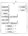
- the CPU 100 measures the blood pressure value of the subject and the heart failure index relatively representing the severity of heart failure by the oscillometric method according to the flow of FIG.
- step S1 of FIG. 4 when the measurement / stop switch 52B is pressed while the power switch 52A is turned on, the sphygmomanometer 1 starts blood pressure measurement.
- the CPU 100 initializes a processing memory area and outputs a control signal to the valve drive circuit 330. Based on the control signal, the valve drive circuit 330 opens the valve 33 and exhausts the air in the fluid bag 22 of the cuff 20. Subsequently, control for adjusting 0 mmHg of the pressure sensor 31 is performed.
- the CPU 100 operates as the cuff pressure control unit 58 (see FIG. 5), closes the valve 33 via the valve drive circuit 330, and then drives the pump 32 via the pump drive circuit 320, thereby fluid bag. Control to send air to 22 is performed. As a result, the fluid bag 22 is inflated and the cuff pressure is gradually increased (steps S3 to S4).
- step S4 When the cuff pressure is increased and reaches a predetermined pressure (YES in step S4), the CPU 100 stops the pump 32 via the pump drive circuit 320 and then gradually turns the valve 33 via the valve drive circuit 330. Control to release. As a result, the fluid bag 22 is contracted and the cuff pressure is gradually reduced (steps S5 to S6).
- the predetermined pressure is a pressure sufficiently higher than the systolic blood pressure of the subject (for example, the systolic blood pressure + 30 mmHg), and is stored in the memory 51 in advance or the CPU 100 performs the systole during the pressurization of the cuff pressure.
- the blood pressure is estimated and determined by a predetermined calculation formula (see, for example, JP-A-2001-70263).
- a target target pressure reduction speed is set during the pressurization of the cuff, and the CPU 100 controls the opening degree of the valve 33 so as to be the target pressure reduction speed (see the same publication).
- the CPU 100 operates as the pressure detection unit 59 (see FIG. 5), detects the pressure of the cuff 20 by the pressure sensor 31, and obtains a cuff pressure signal (denoted by the symbol Pc). Based on this cuff pressure signal Pc, the CPU 100 calculates blood pressure values (systolic blood pressure and diastolic blood pressure) by applying an algorithm described later by an oscillometric method (step S6).
- the calculation of the blood pressure value is not limited to the decompression process, and may be performed in the pressurization process.
- step S6 When the blood pressure value is calculated and determined (YES in step S6), in this example, the CPU 100 immediately opens the valve 33 via the valve drive circuit 330 and exhausts the air in the fluid bag 22 of the cuff 20 (rapid exhaust). ) Is performed (step S7).
- step S8 the CPU 100 calculates a heart failure index that relatively represents the severity of heart failure by an algorithm described later.
- the CPU 100 works as the display processing unit 71 (see FIG. 5), and displays the calculated blood pressure value and heart failure index on the display 50 (step S9). In addition, the CPU 100 performs control to save the blood pressure value and the heart failure index in the memory 51.
- FIG. 5 illustrates elements configured by the CPU 100 (software) of the sphygmomanometer 1 for calculating the blood pressure value and the heart failure index.
- the above-described cuff pressure control unit 58, pressure detection unit 59, and display processing unit 71 are also shown.
- the elements for calculating the blood pressure value and the heart failure index are the pulse wave amplitude sequence acquisition unit 61, the first envelope generation unit 62, the extreme point detection unit 63, the maximum point envelope generation unit 64, and the minimum point envelope.
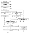
- FIG. 6 shows the flow of processing when calculating the blood pressure value and the heart failure index using those elements in FIG.
- the pulse wave amplitude train acquisition unit 61 in FIG. 5 receives the cuff pressure signal Pc detected by the pressure sensor 31 and superimposes it on the cuff pressure signal Pc, as shown in FIG. A pulse wave signal SM representing the pulse wave of the measurement site is extracted.
- the cuff pressure signal Pc corresponds to a pressure that increases (pressurization process) or decreases (decompression process) substantially linearly with time. It is a signal on which a fluctuation component accompanying an arterial volume change is superimposed.
- the pulse wave amplitude string acquisition unit 61 extracts a fluctuation component (HPF output) as shown in FIG. 7B from the cuff pressure signal Pc through a high pass filter (HPF), and outputs it as a pulse wave signal SM as shown in FIG. To do.
- the pulse wave signal SM starts to increase in about 12 seconds from the start of the measurement, reaches a maximum in about 16 seconds, and increases to about 16 seconds. Almost disappeared in 20 seconds.
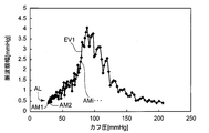
- the pulse wave amplitude string acquisition unit 61 acquires a string AL of the amplitude indicated by the pulse wave signal SM (hereinafter referred to as “pulse wave amplitude” as appropriate).
- the pulse wave amplitude column AL has an amplitude (peak value) for each beat on the plane in which the cuff pressure and the pulse wave amplitude form orthogonal coordinates on the horizontal axis. ) AM 1 , AM 2 ,..., AM i ,.
- the first envelope creation unit 62 in FIG. 5 performs the operation on the pulse wave amplitude sequence AL acquired by the pulse wave amplitude sequence acquisition unit 61.
- a first envelope EV1 that connects the amplitudes is created.
- the first envelope EV1 has irregularities due to respiratory changes.
- FIG. 10 shows, for reference, when the subject's respiratory cycle is known, an amplitude column is generated for each of the respiratory cycle phases ⁇ 1, ⁇ 2,..., ⁇ 5 from the pulse wave amplitude column AL of the pulse wave signal SM.
- envelopes EV ⁇ 1, EV ⁇ 2,..., EV ⁇ 5 are respectively obtained for the amplitude columns for the phases ⁇ 1, ⁇ 2,.
- the phases ⁇ 1, ⁇ 2,..., ⁇ 5 are different from each other by 60 °, where one breathing cycle is 360 °.
- EV ⁇ 5 corresponds to an envelope when the respiratory change shows a maximum
- EV ⁇ 2 corresponds to an envelope when the respiratory change shows a minimum.
- the upper limit line and lower limit for the respiratory fluctuation are taken into account when the respiratory fluctuation shows the maximum and the envelope when the respiratory fluctuation shows the minimum, respectively. Can be considered a line.
- the pole detection unit 63 in FIG. 5 detects the maximum point Lmax and the minimum point Lmin in the first envelope EV1, as shown in FIG.
- the maximum point Lmax and the minimum point Lmin each form a row of a plurality of points.
- the maximal point envelope creation unit 64 in FIG. 5 performs an amplitude sequence corresponding to the maximal point Lmax in the pulse wave amplitude sequence AL acquired by the pulse wave amplitude sequence acquisition unit 61. As shown in FIG. 11, a maximum point envelope EVmax connecting the amplitudes is created.
- the minimum point envelope creation unit 65 in FIG. 5 applies the amplitude sequence corresponding to the minimum point Lmin in the pulse wave amplitude sequence AL acquired by the pulse wave amplitude sequence acquisition unit 61 to FIG. As shown in the figure, a minimum point envelope EVmin connecting these amplitudes is created.
- the threshold level setting unit 66 in FIG. 5 obtains the systolic blood pressure BPsys and the diastolic blood pressure BPdia, respectively, with a predetermined ratio with respect to the value of the maximum peak EV1P in the first envelope EV1.
- the first threshold level Ths and the second threshold level Thd are calculated and set.
- the first threshold level Ths is set to 40% of the value of the maximum peak EV1P
- the second threshold level Thd is set to 50% of the value of the maximum peak EV1P.
- the systolic blood pressure calculation unit 67 in FIG. 5 is on the higher pressure side than the maximum peaks EVmaxP and EVminP of the maximum point envelope EVmax and the minimum point envelope EVmin.
- Two pressure values Pc1 and Pc2 at a point where the portion crosses the first threshold level Ths are obtained.
- the systolic blood pressure calculation unit 67 calculates the average value (Pc1 + Pc2) / 2 of these two pressure values as the systolic blood pressure BPsys.
- the diastolic blood pressure calculation unit 68 calculates the average value (Pc3 + Pc4) / 2 of these two pressure values as the diastolic blood pressure BPdia.
- the maximum point envelope EVmax and the minimum point envelope EVmin correspond to the upper limit line and the lower limit line of respiratory change, respectively. Therefore, it can be said that the average value (Pc1 + Pc2) / 2 of the two high-pressure side pressure values and the average value (Pc3 + Pc4) / 2 of the two low-pressure side pressure values are average values taking into account respiratory changes.
- this electronic sphygmomanometer 1 it is possible to calculate an average blood pressure value in consideration of respiratory change.
- the fluctuation amount calculation unit 69 in FIG. 5 performs respiration based on the maximum point envelope EVmax, the minimum point envelope EVmin, and in this example, the systolic blood pressure BPsys.
- the blood pressure fluctuation amount (respiratory fluctuation) ⁇ BP synchronized with is calculated.
- the blood pressure fluctuation amount ⁇ BP1 as shown in FIG. 12 is calculated as the blood pressure fluctuation amount ⁇ BP.
- This blood pressure fluctuation amount ⁇ BP1 is determined as a difference (first difference) between the pulse wave amplitude taken by the maximum point envelope EVmax and the pulse wave amplitude taken by the minimum point envelope EVmin at a certain cuff pressure.
- the systolic blood pressure BPsys calculated by the systolic blood pressure calculating unit 67 is employed as the “certain cuff pressure”.
- the blood pressure fluctuation amount (respiratory fluctuation) ⁇ BP synchronized with the respiration can be actually obtained.
- each pulse wave amplitude value is created with a normalized pulse wave amplitude value normalized by the maximum value of the first envelope EV1. Then it is better.
- the index output unit 70 in FIG. 5 outputs a predetermined value corresponding to the blood pressure fluctuation amount ⁇ BP as a heart failure index HFI relatively representing the severity of heart failure.
- the index output unit 70 refers to the correspondence C between the blood pressure fluctuation amount and the heart failure index shown in FIG. 3 stored in advance in the memory 51, and the blood pressure fluctuation amount ⁇ BP (in this example)
- the heart failure index HFI corresponding to the blood pressure fluctuation amount ⁇ BP1) shown in FIG. 12 is obtained. Thereby, the heart failure index HFI can be output smoothly.
- the variable x represents the blood pressure fluctuation amount ⁇ BP
- the variable y represents the heart failure index HFI.
- the heart failure index HFI is represented by a one-digit number from 1 to 5, rounded to the nearest decimal point.
- the heart failure index HFI is set to 1.
- the heart failure index HFI is bundled with 5. If the heart failure index HFI is expressed by a single digit in this way, it is easy for a general user to understand the severity of heart failure.
- the display processing unit 71 in FIG. 5 performs processing for displaying the calculated heart failure index HFI on the display device 50 together with the calculated blood pressure values (systolic blood pressure BPsys and diastolic blood pressure BPdia).
- the “maximum blood pressure” display area 501 for displaying the value of the systolic blood pressure BPsys and the value of the diastolic blood pressure BPdia are displayed in order from the top.
- “Minimum blood pressure” display area 502 to display, “Pulse rate” display area 503 to display the pulse rate, “Heart failure index” display area 504 to display the value of the heart failure index HFI, and the measurement date and time are displayed A measurement date / time display area 505 is provided.
- 145 mmHg is displayed in the “maximum blood pressure” display area 501
- 90 mmHg is displayed in the “minimum blood pressure” display area 502
- 75 beats / minute is displayed in the “pulse rate” display area 503
- the heart failure index is displayed in the “heart failure index” display area 504.
- “4” as the numerical value of “” and “2017/12/1 7:00” as the measurement date and time are displayed in the measurement date display area 505.
- the large and small values of the heart failure index HFI correspond to the severity and severity of heart failure.
- the user can know whether or not the state of heart failure has deteriorated by looking at the numerical value of the heart failure index displayed in the “heart failure index” display area 504. If the state of heart failure has deteriorated, appropriate measures can be taken, such as visiting a hospital and receiving a doctor's examination even on a day other than the scheduled examination date.
- the cuff pressure control unit 58 using the pump 32 and the valve 33 and the pressure detection unit 59 using the pressure sensor 31 are general commercially available electronic sphygmomanometers for obtaining the blood pressure of the measurement site by the oscillometric method. It is a constituent element that does not require invasiveness to the subject. Further, the elements 61 to 71 configured by the CPU 100 shown in FIG. 5 are components that perform calculations using the cuff pressure signal Pc and the blood pressure fluctuation amount ⁇ BP (a quantity obtained based on the cuff pressure signal Pc), respectively. And does not require invasion of the subject. Therefore, this sphygmomanometer 1 can output the heart failure index HFI non-invasively to the subject.
- NT-proBNP N-terminal pro-B-type natriuretic peptide
- NT-proBNP is 125 (pg / ml) or more, and that there is a possibility of heart failure to be treated at 900 (pg / ml) or more.
- NT-proBNP is considered to have a large individual difference because it may show a high value (level) depending on factors other than heart failure such as a decrease in renal function.
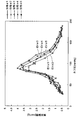
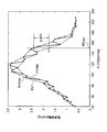
- FIG. 15 and 16 show, for example, the maximum point envelope EVmax and the minimum point envelope EVmin created by the sphygmomanometer 1 for the patient B on the hospitalization date and the discharge date, respectively.
- NT-proBNP 2550.6 [pg / ml]
- the severity of heart failure was relatively heavy.
- the difference between the maximum point envelope EVmax and the minimum point envelope EVmin was relatively large, and the blood pressure fluctuation amount ⁇ BP was also relatively large.
- NT-proBNP 471.8 [pg / ml]
- the severity of heart failure was relatively light.
- the difference between the maximum point envelope EVmax and the minimum point envelope EVmin was relatively small, and the blood pressure fluctuation amount ⁇ BP was also relatively small. The same tendency was observed for patient A.
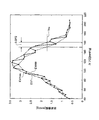
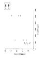
- FIG. 17 shows the blood pressure fluctuation amount ⁇ BP ( ⁇ BP1 shown in FIG. 12 in this example) measured by the sphygmomanometer 1 and the NT-proBNP measured on the hospitalization date and the hospital discharge date, respectively.
- the relationship is shown as a scatter diagram.
- the ⁇ marks indicate the data of patient A
- the ⁇ marks indicate the data of patient B. According to FIG. 17, it can be seen that in both patients A and B, the blood pressure fluctuation amount ⁇ BP increases as NT-proBNP increases.
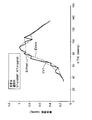
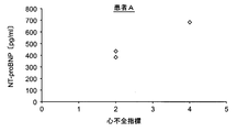
- FIG. 18A shows, as a scatter diagram, the relationship between the heart failure index HFI measured by the sphygmomanometer 1 and NT-proBNP, measured for the patient A on the hospitalization date and the discharge date.
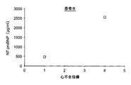
- FIG. 18B shows, as a scatter diagram, the relationship between the heart failure index HFI measured by the sphygmomanometer 1 and NT-proBNP measured for the patient B on the hospitalization date and the discharge date.
- the heart failure index HFI by the sphygmomanometer 1 corresponds to the large and small of NT-proBNP. Therefore, it can be said that the heart failure index HFI by the sphygmomanometer 1 relatively represents the severity of heart failure.
- the levels of NT-proBNP values are relatively different, but this is considered to be due to individual differences as described above.
- HFI heart failure index
- sphygmomanometer 1 For patient B, taking into account the value of NT-proBNP on the hospital admission date and discharge date, for example, when the heart failure index HFI by sphygmomanometer 1 is 2 or 3 or more, measures such as visiting a hospital and seeing a doctor It is recommended to take Thus, this sphygmomanometer 1 can be used for home monitoring and / or screening for heart failure.
- the heart failure index HFI by the sphygmomanometer 1 is equal to or greater than a predetermined threshold value (for example, 3 or more as a value to be examined by a doctor), the value of the heart failure index HFI is not simply displayed on the display 50.
- the CPU 100 may act as an alarm unit to notify the user of this by, for example, blinking the numerical value of the heart failure index HFI in the display screen 500 or sounding an alarm sound with the buzzer 55. This clearly prompts the user to see a doctor.
- the threshold value for the CPU 100 to function as an alarm unit can be variably set by operating the operation unit 52, for example. Thereby, the said threshold value can be appropriately set according to each test subject (patient).
- the blood pressure fluctuation amount (respiratory fluctuation) ⁇ BP synchronized with respiration is the blood pressure fluctuation amount ⁇ BP1 shown in FIG.
- the difference (first difference) between the pulse wave amplitude taken by the maximum point envelope EVmax and the pulse wave amplitude taken by the minimum point envelope EVmin was assumed.
- the blood pressure fluctuation amount ⁇ BP may be a ratio (first ratio) between the pulse wave amplitude taken by the maximum point envelope EVmax and the pulse wave amplitude taken by the minimum point envelope EVmin at a certain cuff pressure.
- the diastolic blood pressure BPdia calculated by the diastolic blood pressure calculating unit 68 may be used instead of the systolic blood pressure BPsys, or the maximum A pressure value obtained by adding a predetermined value (for example, 10 mmHg) to the cuff pressure giving the maximum peak EVmaxP or EVminP of the point envelope EVmax or the minimum point envelope EVmin may be used.
- a predetermined value for example, 10 mmHg
- a plurality of “certain cuff pressures” that give the first difference or ratio may be set.
- statistical processing for example, processing for obtaining an average value
- the blood pressure fluctuation amount ⁇ BP is obtained.
- the blood pressure fluctuation amount (respiratory fluctuation) ⁇ BP synchronized with respiration is the blood pressure fluctuation amount ⁇ BP2 shown in FIG. 13, that is, the maximum point envelope EVmax shown in FIG.
- the maximum point envelope EVmax takes a certain pulse wave amplitude (for example, the first threshold level Ths) at a portion higher than the maximum peaks EVmaxP and EVminP of the maximum point envelope EVmax and the minimum point envelope EVmin. It may be a ratio (second ratio) between the cuff pressure Pc1 and the cuff pressure Pc2 taken by the minimum point envelope EVmin.
- the maximum point envelope EVmax takes a certain pulse wave amplitude (for example, the second threshold level Thd) at a portion lower than the maximum peaks EVmaxP and EVminP of the maximum point envelope EVmax and the minimum point envelope EVmin. It may be a difference or ratio between the cuff pressure Pc3 and the cuff pressure Pc4 taken by the minimum point envelope EVmin.
- the “certain pulse wave amplitude” that gives the second difference or ratio is a portion on the high-pressure side and a portion on the low-pressure side of the maximum peaks EVmaxP and EVminP of the maximum point envelope EVmax and the minimum point envelope EVmin.
- Each of the first threshold level Ths and the second threshold level Thd may be changed and set.
- a plurality of “certain pulse wave amplitudes” giving the second difference or ratio may be set.
- statistical processing for example, processing for obtaining an average value
- the blood pressure fluctuation amount ⁇ BP can be determined in various ways based on the deviation (respiratory fluctuation) between the maximum point envelope EVmax and the minimum point envelope EVmin. In this case, it is desirable that the correspondence relationship C (FIG. 3) between the blood pressure fluctuation amount and the heart failure index is reset according to the definition of the blood pressure fluctuation amount.
- the heart failure index HFI is expressed by a single digit from 1 to 5, rounded to the nearest decimal point.
- the heart failure index HFI may be represented by a single digit from 1 to 9, for example, or may be represented by a numerical value of two or more digits.
- the value of the heart failure index HFI increases as the severity of heart failure increases.
- the present invention is not limited to this.
- the numerical value of the heart failure index HFI may be decreased as the severity of heart failure increases. Good.
- the measurement site is the upper arm 90, but is not limited thereto.
- the part to be measured may be a wrist or a leg.
- the main body 10 and the cuff 20 of the sphygmomanometer 1 may be integrated.
- the electronic sphygmomanometer (sphygmomanometer 1) has been described, but is not limited thereto.
- the present invention may be embodied as a heart failure detector instead of an electronic sphygmomanometer.
- the heart failure detector has the same appearance (see FIG. 1) and the same block configuration (see FIG. 2) as in the sphygmomanometer 1, is non-invasive to the subject, and has the heart failure index shown in FIG. The same processing as that for calculation is executed.
- the heart failure detector displays only information on the heart failure index (“heart failure index 4” in the example of FIG. 14) on the display screen 500 of the display 50 shown in FIG.
- the user can know whether or not the state of heart failure has deteriorated by this heart failure index. If the state of heart failure has deteriorated, appropriate measures can be taken, such as visiting a hospital and receiving a doctor's examination even on a day other than the scheduled examination date.
- the present invention can be embodied as various devices.
Landscapes
- Health & Medical Sciences (AREA)
- Life Sciences & Earth Sciences (AREA)
- Engineering & Computer Science (AREA)
- Medical Informatics (AREA)
- General Health & Medical Sciences (AREA)
- Surgery (AREA)
- Animal Behavior & Ethology (AREA)
- Public Health (AREA)
- Veterinary Medicine (AREA)
- Molecular Biology (AREA)
- Pathology (AREA)
- Biomedical Technology (AREA)
- Heart & Thoracic Surgery (AREA)
- Physics & Mathematics (AREA)
- Biophysics (AREA)
- Physiology (AREA)
- Cardiology (AREA)
- Vascular Medicine (AREA)
- Signal Processing (AREA)
- Psychiatry (AREA)
- Computer Vision & Pattern Recognition (AREA)
- Artificial Intelligence (AREA)
- Ophthalmology & Optometry (AREA)
- Nuclear Medicine, Radiotherapy & Molecular Imaging (AREA)
- Radiology & Medical Imaging (AREA)
- Computing Systems (AREA)
- Computer Networks & Wireless Communication (AREA)
- Measuring Pulse, Heart Rate, Blood Pressure Or Blood Flow (AREA)
- Pulmonology (AREA)
Priority Applications (3)
| Application Number | Priority Date | Filing Date | Title |
|---|---|---|---|
| CN201980025535.5A CN112040853B (zh) | 2018-04-20 | 2019-02-28 | 电子血压计以及心力衰竭检测器 |
| DE112019002064.1T DE112019002064T5 (de) | 2018-04-20 | 2019-02-28 | Elektronisches blutdruckmessgerät und herzfehler-detektor |
| US17/062,666 US20210015374A1 (en) | 2018-04-20 | 2020-10-05 | Electronic blood pressure meter and heart failure detector |
Applications Claiming Priority (2)
| Application Number | Priority Date | Filing Date | Title |
|---|---|---|---|
| JP2018081746A JP7024576B2 (ja) | 2018-04-20 | 2018-04-20 | 電子血圧計および心不全検出器 |
| JP2018-081746 | 2018-04-20 |
Related Child Applications (1)
| Application Number | Title | Priority Date | Filing Date |
|---|---|---|---|
| US17/062,666 Continuation US20210015374A1 (en) | 2018-04-20 | 2020-10-05 | Electronic blood pressure meter and heart failure detector |
Publications (1)
| Publication Number | Publication Date |
|---|---|
| WO2019202856A1 true WO2019202856A1 (ja) | 2019-10-24 |
Family
ID=68239563
Family Applications (1)
| Application Number | Title | Priority Date | Filing Date |
|---|---|---|---|
| PCT/JP2019/007725 Ceased WO2019202856A1 (ja) | 2018-04-20 | 2019-02-28 | 電子血圧計および心不全検出器 |
Country Status (5)
| Country | Link |
|---|---|
| US (1) | US20210015374A1 (enExample) |
| JP (1) | JP7024576B2 (enExample) |
| CN (1) | CN112040853B (enExample) |
| DE (1) | DE112019002064T5 (enExample) |
| WO (1) | WO2019202856A1 (enExample) |
Citations (6)
| Publication number | Priority date | Publication date | Assignee | Title |
|---|---|---|---|---|
| JP2009501557A (ja) * | 2005-06-21 | 2009-01-22 | アーリーセンス エルティディ | 臨床症状の予測および監視技術 |
| US20100106030A1 (en) * | 2008-10-23 | 2010-04-29 | Mason Gregory R | Method and system for automated measurement of pulsus paradoxus |
| JP2012200507A (ja) * | 2011-03-28 | 2012-10-22 | Omron Healthcare Co Ltd | 電子血圧計および演算プログラム |
| JP2014168574A (ja) * | 2013-03-04 | 2014-09-18 | Omron Healthcare Co Ltd | 電子血圧計 |
| JP2015009044A (ja) * | 2013-07-01 | 2015-01-19 | オムロンヘルスケア株式会社 | 電子血圧計 |
| WO2016013684A1 (ja) * | 2014-07-22 | 2016-01-28 | 帝人ファーマ株式会社 | 心不全の評価方法および診断装置 |
Family Cites Families (21)
| Publication number | Priority date | Publication date | Assignee | Title |
|---|---|---|---|---|
| US5090418A (en) * | 1990-11-09 | 1992-02-25 | Del Mar Avionics | Method and apparatus for screening electrocardiographic (ECG) data |
| IL145445A (en) * | 2001-09-13 | 2006-12-31 | Conmed Corp | A method for signal processing and a device for improving signal for noise |
| US8594790B2 (en) * | 2005-01-27 | 2013-11-26 | Medtronic, Inc. | System and method for monitoring a ventricular pressure index to predict worsening heart failure |
| US7634309B2 (en) * | 2005-08-19 | 2009-12-15 | Cardiac Pacemakers, Inc. | Tracking progression of congestive heart failure via a force-frequency relationship |
| US20120095304A1 (en) * | 2005-12-15 | 2012-04-19 | Cardiopulmonary Corporation | System and Method for Determining a Patient Clinical Status |
| EP1965695B1 (en) * | 2005-12-19 | 2011-05-11 | Koninklijke Philips Electronics N.V. | Monitoring apparatus for monitoring a user's heart rate and/or heart rate variation; wristwatch comprising such a monitoring apparatus |
| US7874992B2 (en) * | 2006-01-31 | 2011-01-25 | Medtronic, Inc. | Method for continuous baroreflex sensitivity measurement |
| US9968266B2 (en) * | 2006-12-27 | 2018-05-15 | Cardiac Pacemakers, Inc. | Risk stratification based heart failure detection algorithm |
| US9713701B2 (en) * | 2008-07-31 | 2017-07-25 | Medtronic, Inc. | Using multiple diagnostic parameters for predicting heart failure events |
| JP2010167181A (ja) * | 2009-01-26 | 2010-08-05 | Omron Healthcare Co Ltd | 電子血圧計、情報処理装置、測定管理システム、測定管理プログラム、および測定管理方法 |
| KR101844077B1 (ko) * | 2009-08-13 | 2018-03-30 | 데이진 화-마 가부시키가이샤 | 호흡 파형 정보의 연산 장치 및 호흡 파형 정보를 이용한 의료 기기 |
| EP2796874B1 (en) * | 2010-08-26 | 2017-03-08 | Roche Diagnostics GmbH | Use of biomarkers in monitoring a medication in a subject suffering from heart failure |
| CA2819886A1 (en) * | 2010-12-06 | 2012-06-14 | Pronota N.V. | Biomarkers and parameters for hypertensive disorders of pregnancy |
| JP5741087B2 (ja) * | 2011-03-11 | 2015-07-01 | オムロンヘルスケア株式会社 | 血圧情報測定装置 |
| US9066659B2 (en) * | 2011-04-08 | 2015-06-30 | Cardiac Pacemakers, Inc. | Transient sensor response to posture as a measure of patient status |
| JP2013090824A (ja) * | 2011-10-26 | 2013-05-16 | Omron Healthcare Co Ltd | 電子血圧計 |
| JP5803641B2 (ja) * | 2011-12-09 | 2015-11-04 | オムロンヘルスケア株式会社 | 電子血圧計 |
| WO2014036173A1 (en) * | 2012-08-28 | 2014-03-06 | The Regents Of The University Of California | Methods and systems for calculating and using statistical models to predict medical events |
| EP4075143A1 (en) * | 2012-09-12 | 2022-10-19 | Roche Diagnostics GmbH | Identification of patients with abnormal fractional shortening |
| MX2016009060A (es) * | 2014-01-10 | 2016-09-09 | Critical Care Diagnostics Inc | Metodos y sistemas para determinar el riesgo de falla cardiaca. |
| US10638980B2 (en) * | 2015-10-13 | 2020-05-05 | Koninklijke Philips N.V. | System and method for predicting heart failure decompensation |
-
2018
- 2018-04-20 JP JP2018081746A patent/JP7024576B2/ja active Active
-
2019
- 2019-02-28 WO PCT/JP2019/007725 patent/WO2019202856A1/ja not_active Ceased
- 2019-02-28 CN CN201980025535.5A patent/CN112040853B/zh active Active
- 2019-02-28 DE DE112019002064.1T patent/DE112019002064T5/de active Pending
-
2020
- 2020-10-05 US US17/062,666 patent/US20210015374A1/en active Pending
Patent Citations (6)
| Publication number | Priority date | Publication date | Assignee | Title |
|---|---|---|---|---|
| JP2009501557A (ja) * | 2005-06-21 | 2009-01-22 | アーリーセンス エルティディ | 臨床症状の予測および監視技術 |
| US20100106030A1 (en) * | 2008-10-23 | 2010-04-29 | Mason Gregory R | Method and system for automated measurement of pulsus paradoxus |
| JP2012200507A (ja) * | 2011-03-28 | 2012-10-22 | Omron Healthcare Co Ltd | 電子血圧計および演算プログラム |
| JP2014168574A (ja) * | 2013-03-04 | 2014-09-18 | Omron Healthcare Co Ltd | 電子血圧計 |
| JP2015009044A (ja) * | 2013-07-01 | 2015-01-19 | オムロンヘルスケア株式会社 | 電子血圧計 |
| WO2016013684A1 (ja) * | 2014-07-22 | 2016-01-28 | 帝人ファーマ株式会社 | 心不全の評価方法および診断装置 |
Also Published As
| Publication number | Publication date |
|---|---|
| JP2019187651A (ja) | 2019-10-31 |
| JP7024576B2 (ja) | 2022-02-24 |
| DE112019002064T5 (de) | 2021-01-14 |
| CN112040853B (zh) | 2023-09-19 |
| CN112040853A (zh) | 2020-12-04 |
| US20210015374A1 (en) | 2021-01-21 |
Similar Documents
| Publication | Publication Date | Title |
|---|---|---|
| CN102791192B (zh) | 增强和分析来自连续无创血压设备的信号的装置 | |
| US10130270B2 (en) | Electronic blood pressure monitor | |
| JP5589501B2 (ja) | 血圧測定装置 | |
| US9326692B2 (en) | Blood pressure measurement device and blood pressure measurement method | |
| JP5985355B2 (ja) | 血液量測定方法および測定装置 | |
| US20090312652A1 (en) | Electronic manometer for appropriately adjusting internal pressure of cuff and method for controlling the same | |
| EP1011436A1 (en) | Method and arrangement for blood pressure measurement | |
| JP2013099505A (ja) | 循環動態測定装置 | |
| CN110840429B (zh) | 基于柯氏音的血压测量方法及血压测量和心血管系统评估系统 | |
| JPWO2012073807A1 (ja) | 簡易な血圧チェック機能付き電子血圧計および当該電子血圧計を用いた血圧測定管理方法 | |
| KR101313496B1 (ko) | 전자혈압계의 정확성 평가 기법 | |
| US11020010B2 (en) | Blood pressure/pulse wave measurement device | |
| JP4227519B2 (ja) | 後細動脈圧の測定のための方法 | |
| WO2019202856A1 (ja) | 電子血圧計および心不全検出器 | |
| JP2012200507A (ja) | 電子血圧計および演算プログラム | |
| US6881190B2 (en) | Standard pulse-wave-propagation-velocity-related-value determining apparatus and pulse-wave-propagation-velocity-related-value obtaining apparatus | |
| JP2013090824A (ja) | 電子血圧計 | |
| JP2019187651A5 (enExample) | ||
| JP2002102184A (ja) | 自動血圧計の計測表示方法 | |
| JP2023085724A (ja) | 血圧測定装置 | |
| CN118697312A (zh) | 一种血压手表的气泵控制方法、装置及血压手表 | |
| JP5353106B2 (ja) | 電子血圧計 | |
| EP3581104A1 (en) | Method, device and computer program product for estimating a compliance of a blood vessel in a subject | |
| AU2013205767A9 (en) | Continuous non-invasive optical measurement of tissue oxygen delivery |
Legal Events
| Date | Code | Title | Description |
|---|---|---|---|
| 121 | Ep: the epo has been informed by wipo that ep was designated in this application |
Ref document number: 19788068 Country of ref document: EP Kind code of ref document: A1 |
|
| 122 | Ep: pct application non-entry in european phase |
Ref document number: 19788068 Country of ref document: EP Kind code of ref document: A1 |