WO2019194116A1 - 光脱臭方法および光脱臭装置 - Google Patents
光脱臭方法および光脱臭装置 Download PDFInfo
- Publication number
- WO2019194116A1 WO2019194116A1 PCT/JP2019/014435 JP2019014435W WO2019194116A1 WO 2019194116 A1 WO2019194116 A1 WO 2019194116A1 JP 2019014435 W JP2019014435 W JP 2019014435W WO 2019194116 A1 WO2019194116 A1 WO 2019194116A1
- Authority
- WO
- WIPO (PCT)
- Prior art keywords
- gas
- ozone
- humidity
- predetermined range
- light
- Prior art date
- Legal status (The legal status is an assumption and is not a legal conclusion. Google has not performed a legal analysis and makes no representation as to the accuracy of the status listed.)
- Ceased
Links
Images


Classifications
-
- A—HUMAN NECESSITIES
- A61—MEDICAL OR VETERINARY SCIENCE; HYGIENE
- A61L—METHODS OR APPARATUS FOR STERILISING MATERIALS OR OBJECTS IN GENERAL; DISINFECTION, STERILISATION OR DEODORISATION OF AIR; CHEMICAL ASPECTS OF BANDAGES, DRESSINGS, ABSORBENT PADS OR SURGICAL ARTICLES; MATERIALS FOR BANDAGES, DRESSINGS, ABSORBENT PADS OR SURGICAL ARTICLES
- A61L9/00—Disinfection, sterilisation or deodorisation of air
- A61L9/015—Disinfection, sterilisation or deodorisation of air using gaseous or vaporous substances, e.g. ozone
-
- A—HUMAN NECESSITIES
- A61—MEDICAL OR VETERINARY SCIENCE; HYGIENE
- A61L—METHODS OR APPARATUS FOR STERILISING MATERIALS OR OBJECTS IN GENERAL; DISINFECTION, STERILISATION OR DEODORISATION OF AIR; CHEMICAL ASPECTS OF BANDAGES, DRESSINGS, ABSORBENT PADS OR SURGICAL ARTICLES; MATERIALS FOR BANDAGES, DRESSINGS, ABSORBENT PADS OR SURGICAL ARTICLES
- A61L9/00—Disinfection, sterilisation or deodorisation of air
- A61L9/16—Disinfection, sterilisation or deodorisation of air using physical phenomena
- A61L9/18—Radiation
- A61L9/20—Ultraviolet radiation
Definitions
- the present invention relates to a light deodorization method and a light deodorization apparatus for removing the odor of a gas to be treated containing a substance causing odor.
- Patent Document 1 International Publication No. WO2017 / 082380 discloses a deodorizing apparatus using an ultraviolet irradiation light source that emits ultraviolet light having a wavelength of 200 to 260 nm and ultraviolet light having a wavelength of 150 to 200 nm. This deodorization apparatus decomposes the odor-causing substance in the gas to be treated by irradiating the gas to be treated with ultraviolet rays having a wavelength of 200 to 260 nm.
- the deodorizing efficiency is improved by using ozone generated by irradiating the oxygen contained in the gas to be treated with ultraviolet rays having a wavelength of 150 to 200 nm.
- ozone is a harmful gas and may adversely affect living organisms.
- ozone which is a by-product of the deodorization process, floats in the breeding room, and the animals in the breeding room are affected by ozone. End up.
- Patent Document 2 Japanese Patent Application Laid-Open No. 2016-022231
- a deodorizing apparatus that decomposes ozone remaining in a processing chamber after a deodorizing process is performed by filling high-concentration ozone.
- the ozone generating ultraviolet light emitting member is turned off to stop the generation of ozone, and the ozone decomposing ultraviolet light emitting member is turned on. The ozone remaining in the processing chamber is decomposed.
- the deodorization process can be performed only in a state where no living organism exists in the processing chamber. Therefore, the present invention provides a light deodorization method and light that can remove odors in a processing chamber while reducing the adverse effects of ozone on the living organisms even when a living organism such as an animal is present in the processing chamber.
- An object is to provide a deodorizing apparatus.
- one aspect of the photodeodorization method according to the present invention is a photodeodorization method for removing the odor-causing substance from the gas to be treated containing the odor-causing substance, and A step of generating a mixed gas having a predetermined range of humidity mixed with ozone; and a step of irradiating the mixed gas having a predetermined range of humidity with deep ultraviolet light that does not generate ozone.
- ozone is decomposed by irradiating a mixed gas having a predetermined range of humidity with deep ultraviolet light (DUV light), and hydroxy radicals (OH radicals) are generated by the decomposition of ozone, and OH radicals are used.
- the odor-causing substance can be decomposed (deodorized). That is, it is possible to generate highly reactive OH radicals and efficiently decompose odor-causing substances using OH radicals. Moreover, since ozone can be decomposed
- the step of generating the mixed gas having the predetermined range of humidity includes the step of humidifying the gas to be processed to the predetermined range of humidity and the target of treatment having the predetermined range of humidity.
- a gas is introduced into an ozone generation space, and the ozone is generated using the gas to be processed having a humidity in the predetermined range in the ozone generation space as a raw material, and the gas to be processed and the ozone having the humidity in the predetermined range; And a step of mixing.
- a mixed gas having a predetermined range of humidity can be appropriately generated.
- the step of generating the mixed gas having the predetermined range of humidity includes the step of humidifying the gas to be processed to the predetermined range of humidity, and the source gas containing oxygen in the ozone generation space. Introducing the ozone in the ozone generation space using the source gas as a source, introducing the ozone into the gas to be processed having a humidity in the predetermined range, and the gas to be processed having the humidity in the predetermined range; And a step of mixing with the ozone.
- a mixed gas having a predetermined range of humidity can be appropriately generated.
- the step of generating the mixed gas having the predetermined range of humidity introduces the gas to be processed into an ozone generation space, and uses the gas to be processed as a raw material in the ozone generation space. And a step of mixing the gas to be processed and the ozone, and a step of humidifying the mixed gas of the gas to be processed and the ozone to a predetermined range of humidity.
- ozone is generated using the gas to be processed as a raw material to generate a mixed gas of the gas to be processed and ozone, and the mixed gas is humidified to a predetermined range of humidity, thereby having a predetermined range of humidity. Can be generated appropriately.
- the step of generating the mixed gas having the humidity in the predetermined range includes introducing a source gas containing oxygen into the ozone generation space, and using the source gas as a source in the ozone generation space. And the step of introducing the ozone into the gas to be treated to mix the gas to be treated and the ozone, and the step of humidifying the mixed gas of the gas to be treated and the ozone to a humidity within the predetermined range. And may be included.
- ozone generated by using a raw material gas containing oxygen as a raw material is introduced into the gas to be processed to generate a mixed gas of the gas to be processed and ozone, and the mixed gas is humidified to a predetermined range of humidity.
- the mixed gas which has a humidity of a predetermined range can be produced
- the ozone may be generated by irradiating a gas in the ozone generation space with vacuum ultraviolet light, or generating a discharge in the gas in the ozone generation space. May be generated. Thereby, ozone can be appropriately generated in the ozone generation space.
- VUV light vacuum ultraviolet light
- singlet oxygen atoms (O ( 1 D)) can be generated by irradiation with VUV light, and O ( 1 D) is used. It is possible to effectively decompose odor-causing substances.
- the gas in the ozone generation space contains moisture, OH radicals can be generated by the reaction between the moisture and VUV light. Therefore, high efficiency using OH radicals prior to the DUV light irradiation step. Odor-causing substances can be decomposed.
- said optical deodorizing method may further include the step of measuring the humidity of the gas to be processed, and when the humidity of the gas to be processed is less than the predetermined range, the step of humidifying may be performed.
- humidity may be measured and a humidification process may be performed as necessary.
- the humidity of the mixed gas used as a process target can be made into the humidity of the predetermined range which can decompose
- the humidity in the predetermined range may be 50% or more and 90% or less. In this case, the odor-causing substance can be appropriately decomposed while suppressing problems caused by the occurrence of dew condensation associated with high humidity.
- one aspect of the light deodorizing apparatus is a light deodorizing apparatus that removes the odor-causing substance of the gas to be treated containing the odor-causing substance, and includes a first light source that emits deep ultraviolet light, The first light source is disposed, and the mixed gas having a humidity in a predetermined range in which the gas to be processed and ozone are mixed is irradiated with the deep ultraviolet light that does not generate the ozone by the first light source. Irradiation space.
- ozone is decomposed by irradiating a mixed gas having a predetermined range of humidity with deep ultraviolet light (DUV light), and hydroxy radicals (OH radicals) are generated by the decomposition of ozone, and OH radicals are used.
- the odor-causing substance can be decomposed (deodorized). That is, it is possible to generate highly reactive OH radicals and efficiently decompose odor-causing substances using OH radicals.
- ozone can be decomposed
- the above-mentioned light deodorizing apparatus is connected to the humidifying device for humidifying the gas to be treated to the predetermined range of humidity and the gas discharge side of the humidifying device, and the predetermined range introduced from the humidifying device.
- An ozone generator that generates a mixed gas having a humidity within the predetermined range, and an ozone generator that generates a mixed gas having a humidity within a predetermined range; and a gas discharge side of the ozone generator;
- a light irradiation device having the light irradiation space into which the mixed gas having the humidity in the predetermined range is introduced.
- ozone is generated by the ozone generator, so that a mixed gas having a predetermined range of humidity can be appropriately generated. Further, by introducing the generated mixed gas having a predetermined range of humidity into the light irradiation space of the light irradiation device, it is possible to appropriately irradiate the mixed gas with the DUV light.
- the light deodorization apparatus includes a humidifier that humidifies the gas to be treated to a predetermined range of humidity, an ozone generator that generates the ozone using a raw material gas containing oxygen as a raw material, Connected to the gas discharge side of the humidifier and the gas discharge side of the ozone generator, respectively, the gas to be treated having the humidity in the predetermined range from the humidifier and the ozone from the ozone generator are introduced. And a light irradiation device having the light irradiation space in which the mixed gas having the humidity in the predetermined range is generated.
- the light irradiation space is introduced by introducing into the light irradiation space the gas to be treated that has been humidified to a predetermined range of humidity by the humidifier and ozone generated by using an ozone generator as a raw material gas. It is possible to appropriately generate a mixed gas having a predetermined range of humidity. Accordingly, it is possible to appropriately irradiate the mixed gas with the DUV light in the light irradiation device.
- the above-described photodeodorization apparatus generates ozone by using the gas to be treated as a raw material, and generates a mixed gas of the gas to be treated and ozone, and the ozone generator.
- a humidifier Connected to the gas discharge side, connected to the gas discharge side of the humidifier, a humidifier that humidifies the mixed gas of the gas to be treated and ozone introduced from the ozone generator to the predetermined range of humidity, A light irradiation device having the light irradiation space into which the mixed gas having the humidity in the predetermined range is introduced from the humidifying device.
- ozone is generated from the gas to be processed by the ozone generator to generate a mixed gas of the gas to be processed and ozone, and the mixed gas is humidified to a predetermined range of humidity by a humidifying device.
- a mixed gas having a humidity in a range can be appropriately generated. Further, by introducing the generated mixed gas having a predetermined range of humidity into the light irradiation space of the light irradiation device, it is possible to appropriately irradiate the mixed gas with the DUV light.
- the light deodorizing apparatus is connected to an ozone generator for generating ozone using a raw material gas containing oxygen as a raw material, and a gas discharge side of the ozone generator, and is introduced from the ozone generator.
- a light irradiation device having the light irradiation space that is connected and into which the mixed gas having the predetermined range of humidity is introduced from the humidifying device.
- the mixture gas having a predetermined range of humidity is obtained by humidifying the gas to be processed and the ozone generated by using an ozone generator as a raw material gas containing oxygen to a predetermined range of humidity using a humidifier. Gas can be generated appropriately. Further, by introducing the generated mixed gas having a predetermined range of humidity into the light irradiation space of the light irradiation device, it is possible to appropriately irradiate the mixed gas with the DUV light.
- the ozone generator may include a second light source that emits vacuum ultraviolet light, and may generate the ozone by irradiating the introduced gas with the vacuum ultraviolet light.
- the ozone generator may include a discharge generation unit that generates a discharge, and may generate the ozone by generating the discharge in an introduced gas. Thereby, ozone can be appropriately generated by the ozone generator.
- It ozone generator for generating a case of VUV ozone generator for generating ozone with a vacuum ultraviolet light (VUV light), singlet oxygen upon irradiation with VUV light (O (1 D)) O ( 1 D) can be used to effectively decompose odor-causing substances. Even in the case of a discharge type ozone generator that generates a discharge in the gas into which the ozone generator is introduced, the O ( 1 D) is generated, and the O ( 1 D) is used to determine the odor-causing substance. It can be decomposed effectively. However, when a discharge ozone generator is used, if nitrogen (N 2 ) is contained in the source gas containing oxygen, NOx is also generated in addition to the above O ( 1 D).
- N 2 nitrogen
- the light deodorization apparatus controls the humidity of the gas to be within a predetermined range based on a humidity sensor that measures the humidity of the gas and a measurement result of the humidity sensor. And a control unit that performs the operation.
- the humidity of the mixed gas in the light irradiation space can be maintained within a predetermined range, and the decomposition of odor-causing substances can be appropriately performed while suppressing problems caused by the occurrence of condensation due to high humidity. It can be carried out.
- the odor in the processing chamber can be removed while reducing the adverse effect of ozone on the living organism.
- FIG. 1 is a configuration block diagram of a light deodorizing apparatus according to the first embodiment.
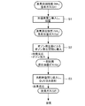
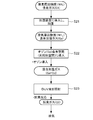
- FIG. 2 is a flowchart for explaining the light deodorization method in the first embodiment.
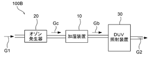
- FIG. 3 is a configuration block diagram of a light deodorizing apparatus according to a modification of the first embodiment.
- FIG. 4 is a flowchart for explaining a light deodorization method according to a modification of the first embodiment.
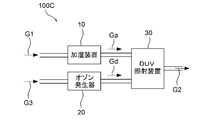
- FIG. 5 is a block diagram showing the configuration of the light deodorizing apparatus according to the second embodiment.
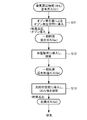
- FIG. 6 is a flowchart for explaining the photodeodorization method in the second embodiment.
- FIG. 7 is a configuration block diagram of a light deodorizing apparatus according to a modification of the second embodiment.
- FIG. 1 is a configuration block diagram of a light deodorizing apparatus according to the first embodiment.
- FIG. 2 is a flowchart for explaining the light deodorization method in the first embodiment.
- FIG. 3 is a configuration block diagram of a light deodorizing apparatus according
- FIG. 8 is a block diagram showing the configuration of a light deodorizing apparatus according to a modification of the second embodiment.
- FIG. 9 is a flowchart for explaining a light deodorization method according to a modification of the second embodiment.
- FIG. 10 is a configuration example of the light deodorization apparatus.
- FIG. 11 is a diagram illustrating a result of the deodorizing process.
- FIG. 1 is a configuration block diagram of a light deodorizing apparatus 100A in the first embodiment
- FIG. 2 is a flowchart for explaining a light deodorizing method in the first embodiment.
- the light deodorization device 100 ⁇ / b> A includes a humidification device 10, an ozone generator 20, and a DUV irradiation device (light irradiation device) 30.
- the light deodorizing apparatus 100A is an ultraviolet irradiation type deodorizing apparatus.
- the optical deodorization apparatus 100A introduces the gas to be treated G1 having an odor-causing substance, performs a deodorizing process for decomposing the odor-causing substance contained in the gas to be treated G1, and discharges the deodorized treated gas G2. .
- the to-be-processed gas G1 containing the odor causing substance is, for example, the atmosphere, and the odor causing substance is, for example, ammonia (NH 3 ). Note that the odor-causing substance is not limited to the above.
- the humidifier 10 humidifies the introduced gas and discharges the gas having a predetermined range of humidity. The humidity in the predetermined range is, for example, 50% or more and 90% or less. In this specification, “humidity” refers to “relative humidity”.
- the ozone generator 20 has an ozone generation space (not shown) and generates ozone in the ozone generation space.
- the ozone generator 20 is a VUV ozone generator that generates ozone by irradiating a gas containing oxygen (O 2 ) with VUV light emitted from a VUV (vacuum ultraviolet light) light source, or oxygen (O 2 ). It can be set as the discharge type ozone generator which generate
- the DUV irradiation apparatus 30 has a light irradiation space (DUV irradiation chamber) (not shown), and irradiates the gas in the DUV irradiation chamber with DUV light emitted from a DUV (deep ultraviolet light) light source.
- the humidifier 10 introduces an NH 3 -containing gas (air) that is the gas to be treated G1 and humidifies the introduced NH 3 -containing gas to a predetermined range of humidity. Then, the humidifier 10 discharges a gas to be processed (NH 3 -containing humidified gas) Ga having a predetermined range of humidity.
- the ozone generator 20 is connected to the gas discharge side of the humidifier 10, generates ozone using NH 3 -containing humidified gas Ga introduced from the humidifier 10 as a raw material, and is a mixed gas having a predetermined range of humidity, that is, humidified
- the mixed humidified gas Gb in which the NH 3 -containing air and ozone are mixed is generated.
- the ozone generator 20 discharges the mixed humidified gas Gb.
- the DUV irradiation apparatus 30 is connected to the gas discharge side of the ozone generator 20 and has a light irradiation space into which the mixed humidified gas Gb is introduced from the ozone generator 20.
- the DUV irradiation apparatus 30 irradiates the mixed humidified gas Gb with DUV light from the DUV light source in the light irradiation space, and discharges the processed gas (deodorized gas) G2 subjected to the deodorizing process.
- Step S ⁇ b> 1 is a process of humidifying the gas to be processed (NH 3 -containing gas) G ⁇ b> 1 containing the odor-causing substance by the humidifier 10.
- the NH 3 -containing gas becomes the NH 3 -containing humidified gas Ga that is the gas to be processed G1 having a predetermined range of humidity. If the cause substances of odor is NH 3, a portion of the NH 3 (e.g., about 10%) is removed dissolved in water NH 3 containing humidified gas Ga.
- Step S2 is a process of introducing ozone into the NH 3 -containing humidified gas Ga.
- the NH 3 -containing humidified gas Ga is introduced into an ozone generation space in the ozone generator 20, and ozone is generated in the ozone generation space using the introduced NH 3 -containing humidified gas Ga as a raw material.
- ozone is mixed with the NH 3 -containing humidified gas Ga to obtain a mixed humidified gas Gb.
- the ozone generator 20 is a VUV type ozone generator
- ozone is generated in the ozone generation space by the following process, for example.
- the VUV light source can be, for example, an Xe excimer lamp that emits VUV light having a wavelength of 172 nm.
- the VUV light source emits light
- the NH 3 -containing humidified gas Ga is irradiated with light having a wavelength of 172 nm.
- highly reactive oxygen atoms (singlet oxygen atoms) O ( 1 D) are directly generated from oxygen in the NH 3 -containing humidified gas Ga by the following reaction formula. Generated.
- NH 3 -containing humidified gas Ga contains moisture by the humidification process described above. According to VUV light having a wavelength of 175 nm or less, hydroxy radicals (OH) are generated from moisture in the NH 3 -containing humidified gas Ga according to the following reaction formula. H 2 O + h ⁇ ( ⁇ 175nm ) ⁇ OH + H ......... (4) causative agent of odor, for example, when a NH 3, NH 3 reacts with the (4) hydroxyl radical (OH radical) generated by the equation Is decomposed. That is, a part of the gas is deodorized by OH radicals. Decomposition of NH 3 by reaction with OH radicals is performed by various reaction processes. For example, NH 3 is decomposed by a reaction represented by the following formula (5). NH 3 + OH ⁇ NH 2 + H 2 O (5)
- step S2 ozone is introduced into the NH 3 -containing humidified gas Ga to generate the mixed humidified gas Gb. In parallel with this, it is generated based on the above equation (1). At least a portion of the decomposition of NH 3 by singlet oxygen atom O (1 D) is carried out. In addition, at least a part of NH 3 is decomposed by OH radicals generated based on the above formula (4). That is, in step S2, the odor-causing substance (NH 3 ) is decomposed to some extent.
- the ozone generator 20 is a NH 3 containing humidified gas Ga is generated ozone as a raw material, NH 3 containing humidified gas Ga and ozone And a part of the odor-causing substance (NH 3 ) is decomposed.
- step S2 the NH 3 -containing humidified gas Ga introduced from the humidifier 20 to the ozone generator 20 contains ozone, and a part of the odor-causing substance (NH 3 ) is decomposed, which is partially deodorized and mixed. It becomes humidified gas Gb.
- Step S3 is a process in which the mixed humidified gas (partially deodorized mixed humidified gas) Gb generated in step S2 is irradiated with deep ultraviolet light (DUV light) having a wavelength of 200 to 300 nm that does not generate ozone.
- the mixed humidified gas Gb is introduced from the ozone generator 20 into the light irradiation space of the DUV irradiation apparatus 30, and the partially deodorized mixed humidified gas Gb is irradiated with DUV light in the light irradiation space.
- DUV light deep ultraviolet light
- the DUV light source can be, for example, a low-pressure mercury lamp that emits DUV light having a center wavelength of 254 nm.
- the mixed humidified gas Gb is irradiated with light having a wavelength of 254 nm.
- ozone is decomposed by the reaction formula shown in the following formula (7). O 3 + h ⁇ (254 nm) ⁇ O 2 + O ( 1 D) (7)
- the optical deodorization apparatus 100A generates a mixed gas having a predetermined range of humidity in which the gas to be processed containing the odor causing substance and ozone are mixed, and has a predetermined range of humidity.
- the mixed gas is irradiated with DUV light that does not generate ozone.
- the optical deodorizing method by the optical deodorizing apparatus 100A in the present embodiment is a step of humidifying the gas to be processed to a predetermined range of humidity (step S1), and a step of mixing the gas to be processed having a predetermined range of humidity and ozone. (Step S2) and a step (Step S3) of irradiating the mixed gas having a predetermined range of humidity with DUV light.
- step S2 the light deodorization apparatus 100A introduces a gas to be processed having a predetermined range of humidity into the ozone generation space, and generates ozone using the gas to be processed having a predetermined range of humidity in the ozone generation space as a raw material. Then, the gas to be processed having a predetermined range of humidity and ozone are mixed.
- step S3 which is the final process, the light deodorization apparatus 100A irradiates a mixed gas having a predetermined range of humidity with DUV light, thereby decomposing ozone and causing odors using OH radicals generated by the decomposition of ozone. Can be decomposed (deodorized).
- the light deodorization apparatus 100A can efficiently generate highly reactive OH radicals, and can efficiently decompose odor-causing substances using the OH radicals.
- the light deodorization apparatus 100A can appropriately decompose the ozone generated in step S2 in the final process. Therefore, ozone is hardly discharged into the processing room (bred room), and the processing room is not filled with high-concentration ozone. Therefore, even when a living organism such as an animal is present in the processing chamber, the adverse effect of ozone on the living organism can be significantly reduced.
- the light deodorizing apparatus 100A irradiates the humidified gas to be processed with VUV light in order to generate ozone in step S2. Therefore, the light deodorization device 100A, in the ozone generating space, to generate singlet oxygen atom O (1 D) (equation (1)), generating reaction decomposing causative agent of odors (equation (3) above) Can be made.
- the light deodorization apparatus 100A generates OH radicals by the reaction between the moisture in the humidified gas containing the odor-causing substance and the VUV light in the ozone generation space (the above formula (4)), and the odor-causing substance is removed.
- a decomposition reaction (formula (5) above) can also occur.
- the light deodorizing apparatus 100A can decompose the odor-causing substance to some extent in step S2 prior to step S3. Therefore, the optical deodorization apparatus 100A can decompose (deodorize) the odor-causing substance with high efficiency.
- FIG. 3 is a configuration block diagram of a light deodorizing apparatus 100B according to a modification of the first embodiment.
- the ozone generator 20 introduces an NH 3 -containing gas (air), which is the gas to be treated G1, and generates ozone using the NH 3 -containing gas G1 as a raw material. Is generated and discharged.
- the humidifier 10 is connected to the gas discharge side of the ozone generator 20, humidifies the mixed gas Gc introduced from the ozone generator 20 to a predetermined range of humidity, and discharges the mixed humidified gas Gb.
- the DUV irradiation device 30 is connected to the gas discharge side of the humidifying device 10 and has a light irradiation space into which the mixed humidified gas Gb is introduced from the humidifying device 10.
- the DUV irradiation apparatus 30 irradiates the mixed humidified gas Gb with DUV light from the DUV light source in the light irradiation space, and discharges the processed gas (deodorized gas) G2 subjected to the deodorizing process.
- FIG. 4 is a flowchart for explaining the light deodorization method according to the modification of the first embodiment.
- the NH 3 -containing gas G1 is first introduced into the ozone generation space of the ozone generator 20, the NH 3 -containing gas G1 is irradiated with VUV light, and oxygen in the NH 3 -containing gas G1 is used as a raw material. Ozone is generated to generate the mixed gas Gc (step S11).
- the NH 3 -containing gas G1 is not humidified, and the NH 3 -containing gas G1 contains little water. Therefore, in step S11, the probability that the secondary reaction (decomposition reaction (2) of the odor causing substance) generated in step S2 of FIG.
- step S11 among the secondary reactions generated in step S2, the decomposition reaction of the odor-causing substance (decomposition reaction of the odor-causing substance ( 1 )) by the singlet oxygen atom O ( 1 D) occurs. . Therefore, in step S11, the NH 3 -containing gas G1 introduced into the ozone generator 20 contains ozone and becomes a partially deodorized mixed gas Gc in which a part of the odor-causing substance (NH 3 ) is decomposed.
- the mixed gas (partially deodorized mixed gas) Gc is humidified to a predetermined range of humidity by the humidifier 10 to become a mixed humidified gas (partially deodorized mixed humidified gas) Gb (step S12). Then, the mixed humidified gas (partially deodorized mixed humidified gas) Gb is introduced into the light irradiation space of the DUV irradiation apparatus 30 and irradiated with DUV light that does not generate ozone in the light irradiation space (step S13).
- the light deodorization apparatus 100B As described above, the light deodorization apparatus 100B according to the present modification generates a mixed gas having a predetermined range of humidity in which the gas to be treated containing the odor-causing substance and ozone are mixed, similarly to the light deodorization apparatus 100A described above. Then, DUV light that does not generate ozone is irradiated to a mixed gas having a predetermined range of humidity. Further, in the photodeodorization method by the photodeodorization apparatus 100B in the present embodiment, as in the photodeodorization method by the photodeodorization apparatus 100A described above, in step S13 which is the final process, ozone decomposition and OH radicals generated by ozone decomposition Can be used to decompose (deodorize) the odor-causing substances.
- the optical deodorization apparatus 100B efficiently generates highly reactive OH radicals and performs high-efficiency odor-causing substance decomposition (deodorization) using the OH radicals. Can do. Further, since the light deodorization apparatus 100B decomposes ozone and discharges it as a treated gas (deodorized gas) G2, even if a living organism such as an animal is present in the processing chamber, ozone is transferred to the living organism. It is possible to significantly reduce adverse effects.
- step S11 the probability of the decomposition reaction (2) of the odor causing substance is low, and the amount of OH radicals generated in parallel with ozone is small. Therefore, compared with 1st embodiment, the decomposition amount of the causative substance of an odor until it reaches
- the odor-causing substance according to this modification can also efficiently decompose the odor-causing substance.
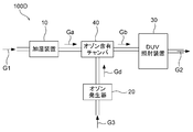
- FIG. 5 is a configuration block diagram of a light deodorizing apparatus 100C according to the second embodiment.
- the humidifier 10 introduces an NH 3 -containing gas (air) that is the gas G1 to be treated, humidifies the NH 3 -containing gas G1 to a predetermined range of humidity, and the NH 3 -containing humidified gas Ga. Is discharged.
- the ozone generator 20 introduces an oxygen-containing gas G3, which is a source gas containing oxygen, generates ozone Gd using the oxygen-containing gas G3 as a raw material, and discharges the ozone Gd.
- the DUV irradiation device 30 is connected to the gas discharge side of the humidifier 10 and the gas discharge side of the ozone generator 20, respectively, and the NH 3 -containing humidified gas Ga from the humidifier 10 and the ozone Gd from the ozone generator 20 Has a light irradiation space into which is introduced.
- the DUV irradiation apparatus 30 irradiates the mixed humidified gas Gb (NH 3 -containing humidified gas Ga + ozone Gd) generated in the light irradiation space with DUV light from a DUV light source, and has processed deodorized gas (deodorized gas). G2 is discharged.
- Gb NH 3 -containing humidified gas Ga + ozone Gd
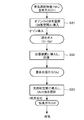
- Step S21 is a process of humidifying the gas to be processed (NH 3 -containing gas) G ⁇ b> 1 containing the odor-causing substance by the humidifier 10.
- step S21 processing similar to that in step S1 in FIG. 2 is performed.
- Step S22 is a process for introducing the NH 3 -containing humidified gas G1 into the ozone-containing space.
- the ozone-containing space is a space into which ozone Gd generated by the ozone generator 20 using a raw material gas (here, an oxygen-containing gas G3) different from the NH 3 -containing humidified gas Ga is introduced. This is a light irradiation space of the irradiation device 30.
- step S22 the NH 3 -containing humidified gas Ga introduced into the ozone-containing space (light irradiation space) is mixed with ozone Gd in the ozone-containing space (light irradiation space) to become a mixed humidified gas (Ga + Gd).
- Step S23 is a process of irradiating the mixed humidified gas (Ga + Gd) generated in step S22 with deep ultraviolet light (DUV light) having a wavelength of 200 to 300 nm that does not generate ozone.
- DUV light deep ultraviolet light
- the optical deodorization apparatus 100C generates a mixed gas having a predetermined range of humidity in which the gas to be treated containing the odor-causing substance and ozone are mixed, similarly to the optical deodorization apparatus 100A described above. Then, DUV light that does not generate ozone is irradiated to a mixed gas having a predetermined range of humidity. Further, in the photodeodorization method using the photodeodorization apparatus 100C in the present embodiment, as in the photodeodorization method using the photodeodorization apparatus 100A described above, in step S23, which is the final process, OH radicals generated by ozone decomposition and ozone decomposition. Can be used to decompose (deodorize) the odor-causing substances.
- the optical deodorization apparatus 100C efficiently generates highly reactive OH radicals and efficiently decomposes (deodorizes) odor-causing substances using the OH radicals. Can do. Further, since the light deodorizing apparatus 100C decomposes ozone and discharges it as a treated gas (deodorized gas) G2, even if a living organism such as an animal is present in the processing chamber, ozone is transferred to the living organism. It is possible to significantly reduce adverse effects.
- the light deodorization apparatus 100C generates ozone Gd using a raw material gas containing oxygen (oxygen-containing gas G3) as a raw material, and introduces the generated ozone Gd into a humidified gas to obtain a mixed humidified gas. ing. Therefore, it becomes possible to easily adjust the amount of ozone contained in the mixed humidified gas.
- oxygen-containing gas G3 oxygen-containing gas
- the NH 3 -containing humidified gas Ga discharged from the humidifier 10 is introduced into the ozone-containing chamber 40 containing the ozone Gd discharged from the ozone generator 20,
- the mixed humidified gas Gb (Ga + Gb) may be generated in the ozone-containing chamber 40 and the mixed humidified gas Gb may be introduced into the DUV irradiation apparatus 30.
- FIG. 8 is a configuration block diagram of a light deodorizing apparatus 100E according to a modification of the second embodiment.
- the ozone generator 20 introduces an oxygen-containing gas G3, which is a raw material gas containing oxygen, generates ozone Gd using the oxygen-containing gas G3 as a raw material, and discharges the ozone Gd.
- the humidifier 10 is connected to the gas discharge side of the ozone generator 20 and has a humidified space into which the ozone Gd from the ozone generator 20 and the NH 3 -containing gas (air) that is the gas to be treated G1 are introduced.
- This humidification space is an ozone-containing space into which ozone Gd generated by the ozone generator 20 using the oxygen-containing gas G3 as a raw material is introduced.
- the humidifier 10 humidifies the mixed gas (G1 + Gd) generated in the humidifying space to a predetermined range of humidity, and discharges the mixed humidified gas Gb.
- the DUV irradiation device 30 is connected to the gas discharge side of the humidifying device 10 and has a light irradiation space into which the mixed humidified gas Gb is introduced from the humidifying device 10.
- the DUV irradiation apparatus 30 irradiates the mixed humidified gas Gb with DUV light from the DUV light source in the light irradiation space, and discharges the processed gas (deodorized gas) G2 subjected to the deodorizing process.
- FIG. 9 is a flowchart for explaining a light deodorization method according to a modification of the second embodiment.
- the NH 3 -containing gas G1 is first introduced into the ozone-containing space (humidified space) of the humidifier 10 to become a mixed gas (G1 + Gd) (step S31).
- This mixed gas (G1 + Gd) is humidified to a predetermined range of humidity by the humidifier 10, and becomes a mixed humidified gas Gb (step S32).
- the mixed humidified gas Gb is introduced into the light irradiation space of the DUV irradiation apparatus 30 and irradiated with DUV light that does not generate ozone in the light irradiation space (step S33).
- the light deodorization apparatus 100E As described above, the light deodorization apparatus 100E according to the present modification generates a mixed gas having a predetermined range of humidity in which the gas to be treated containing the odor causing substance and ozone are mixed, similarly to the above-described light deodorization apparatus 100A. Then, DUV light that does not generate ozone is irradiated to a mixed gas having a predetermined range of humidity.
- step S33 which is the final process, ozone decomposition and OH radicals generated by ozone decomposition Can be used to decompose (deodorize) the odor-causing substances.
- the optical deodorization apparatus 100E efficiently generates highly reactive OH radicals and efficiently decomposes (deodorizes) odor-causing substances using OH radicals. Can do. Moreover, since the light deodorizing apparatus 100E decomposes
- the light deodorization apparatus 100E generates ozone Gd using a raw material gas containing oxygen (oxygen-containing gas G3) as a raw material, and humidifies the mixed gas obtained by mixing the generated ozone Gd and the gas to be processed, thereby mixing the humidified gas. Like to get. Therefore, it becomes possible to easily adjust the amount of ozone contained in the mixed humidified gas.
- oxygen-containing gas G3 oxygen-containing gas
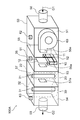
- FIG. 10 is a configuration example of the light deodorizing apparatus 100A according to the present invention.
- This light deodorizing apparatus 100A is an apparatus for realizing the light deodorizing method according to the first embodiment described above.
- the light deodorizing apparatus 100A is installed in a processing room (breeding room) in which living organisms (animals) exist, and decomposes a substance that causes a bad odor in the air (treated gas G1) in the processing room.
- the light deodorizing apparatus 100 ⁇ / b> A includes a housing 50.
- the housing 50 can have a rectangular parallelepiped shape with a width of 40 cm, a depth of 25 cm, and a height of 50 cm, for example.
- a first space 51, a second space 52, a third space 53, and a fourth space 54 are formed in the housing 50.
- the first space 51 and the second space 52 are spatially connected by an opening 55 a provided in the first partition wall 55.
- the second space 52 and the third space 53 are spatially connected by an opening 56 a provided in the second partition wall 56.
- the third space 53 and the fourth space 54 are spatially connected by an opening 57 a provided in the third partition wall 57.
- the first space 51 is a gas introduction chamber for introducing the gas G1 to be processed into the second space 52.
- a suction port 58 for sucking the gas to be processed G ⁇ b> 1 containing the odor-causing substance into the gas introduction chamber 51 is provided.
- the gas to be treated G1 containing substances causing odor for example, NH 3 containing gas containing NH 3 as causative agents of odor.
- the gas to be processed G1 is an atmosphere containing NH 3 existing outside the housing 50.
- emitted from the ventilation part 60 is ventilated to the 2nd space 52 through the opening part 55a.
- the second space 52 is a humidification chamber into which the gas to be processed G1 is introduced from the first space (gas introduction chamber) 51 and humidifies the gas to be processed G1.
- the humidifying device 10 is disposed in the humidifying chamber 52, and the gas G1 introduced into the humidifying chamber 52 through the opening 55a is humidified by the humidifying device 10 in the humidifying chamber 52.
- the humidifier 10 has a structure in which, for example, a part of a filter paper 12 having a loose shape is immersed in water stored in a water tank 11.
- the to-be-treated gas G1 containing the odor-causing substance blown from the blower 60 is blown onto the filter paper 12 that has absorbed water, whereby the to-be-treated gas G1 containing the odor-causing substance is humidified.
- the humidity of the gas to be processed G1 (NH 3 -containing humidified gas Ga) humidified by the humidifier 10 having the above structure controls the air volume of the gas to be processed G1 sent from the blower 60, the temperature of water in the water tank, and the like. By doing so, the humidity can be adjusted to a predetermined range.
- substantially moisture NH 3 containing humidified gas Ga does not become close to 100%. Therefore, it is possible to suppress the occurrence of dew condensation in the apparatus due to high humidity and to suppress the apparatus malfunction due to the dew condensation.
- the light deodorization apparatus 100 ⁇ / b> A may include a humidity sensor 61 that measures the humidity in the humidification chamber 52.
- the humidity sensor 61 can be provided on one surface of the housing 50 so that the sensing unit of the sensor 61 is exposed in the humidification chamber 52. Since the humidity of the NH 3 -containing humidified gas Ga in the humidification chamber 52 can be grasped from the sensing result of the humidity sensor 61, for example, a control device (control unit) (not shown) is based on the sensing result of the humidity sensor 61. In addition, the operation of the humidifier 10 and the operation of the air blowing unit 60 can be controlled.
- the humidity of the NH 3 -containing humidified gas Ga is a humidity within a predetermined range so that the humidity is not so high that the above-described problems occur but the minimum required humidity for effectively decomposing the odor-causing substance. It is preferable that For example, the humidity of the NH 3 -containing humidified gas Ga is preferably 50% or more and 90% or less.
- the third space 53 is an ozone generation chamber in which the NH 3 -containing humidified gas Ga is introduced from the second space (humidification chamber) 52 and ozone is generated using the NH 3 -containing humidified gas Ga as a raw material.
- the ozone generator 20 is disposed inside the ozone generation chamber 53.
- the ozone generator 20 includes a VUV light source (second light source) 21.
- the VUV light source 21 can be, for example, an Xe excimer lamp that emits VUV light having a wavelength of 172 nm.
- NH 3 containing humidified gas Ga are the humidified air containing NH 3
- ozone is generated by the oxygen of the NH 3 containing humidified gas Ga.
- the mixed humidified gas Gb in which the NH 3 -containing humidified gas Ga and ozone are mixed is generated.
- the third space 53 is also a deodorization treatment chamber that decomposes the causative substance of the off-flavor contained in the NH 3 -containing humidified gas Ga by the light irradiation treatment.
- the fourth space 54 is an ozone decomposition chamber into which the mixed humidified gas Gb is introduced from the third space (ozone generation chamber) 53 and decomposes ozone contained in the mixed humidified gas Gb. Further, the fourth space 54 is also a deodorization treatment chamber that decomposes a causative substance of a strange odor remaining in the mixed humidified gas Gb by light irradiation treatment.
- the DUV irradiation device 30 is arranged inside the fourth space 54.
- the DUV irradiation apparatus 30 includes a DUV light source (first light source) 31.
- the DUV light source 31 can be, for example, a low-pressure mercury lamp that emits DUV light having a center wavelength of 254 nm.
- the mixed humidified gas Gb introduced into the fourth space 54 from the opening 57a enters the DUV light arrival space 32 surrounding the DUV light source 31, and is irradiated with the DUV light. At this time, ozone is decomposed in the arrival space 32 of the DUV light. Furthermore, the odor causing substance is also decomposed by OH radicals generated by the reaction between O ( 1 D) generated by ozonolysis and moisture in the mixed humidified gas Gb. Then, the treated gas G ⁇ b> 2 that has been deodorized and ozone-decomposed in the fourth space 54 is discharged from the discharge port 59 into the processing chamber outside the housing 50.
- a power supply unit that supplies power to the VUV light source 21 and the DUV light source 31 and a power supply unit that supplies power to the blower 60 are omitted.
- the third space 53 and the fourth space 54 are partitioned by the third partition wall 57, but the third partition wall 57 may be omitted.
- the light deodorizing apparatus 100A may include a different odor causing substance sensor 62 that measures the concentration of the different odor causing substance in the gas introduction chamber (first space) 51.
- the odor causing substance sensor 62 is provided so that the sensing part of the sensor 62 is exposed in the gas introduction chamber 51. Since the odor level in the processing chamber can be grasped from the sensing result of the off-flavor substance sensor 62, for example, a control device (not shown) operates the light deodorizing apparatus 100A based on the sensing result of the off-flavor substance sensor 62. It is also possible to perform ON / OFF control.
- the light deodorization apparatus 100A may include an ozone sensor 63 that measures the ozone concentration in the fourth space 54 that is an ozone decomposition chamber.
- the ozone sensor 63 is provided such that the sensing unit of the sensor 63 is exposed in the ozone decomposition chamber 54. Since the ozone concentration in the ozone decomposition chamber 54 can be grasped from the sensing result of the ozone sensor 63, for example, a control device (not shown) supplies power to the DUV light source 31 based on the sensing result of the ozone sensor 63. It is also possible to control the amount.
- the control device determines that ozone decomposition is not properly performed in the ozone decomposition chamber 54 and operates the light deodorizing device 100A. You may make it stop.
- the light deodorization apparatus 100A may include an abnormality detection means for detecting an abnormality of the DUV light source 31.
- the abnormality detection unit may be a sensor that senses light emitted from the DUV light source 31, a sensor that detects the amount of power supplied to the DUV light source 31, or the like. In this case, it is possible to detect an abnormality in which the DUV light source 31 does not light normally for some reason. Thereby, when the abnormality of the DUV light source 31 is detected, it is possible to stop the operation of the light deodorizing apparatus 100A and prevent the ozone generated by the deodorizing process from being discharged into the processing chamber.
- the light deodorizing apparatus 100A measures the humidity of the gas to be treated G1 introduced into the housing 50 to determine whether humidification is necessary.
- the gas G1 to be treated may be humidified by the humidifier 10 by operating.
- the installation position of the humidity sensor for measuring the humidity of the gas to be processed G1 can be the vicinity of the suction port 58 or the first space 51.
- the humidifier 10 is configured to be able to switch between a mode in which the gas to be processed G1 is humidified and a mode in which the gas to be processed G1 is not humidified according to the measurement result of the humidity of the gas to be processed G1.
- the mode switching method is not particularly limited.
- the VUV light source 21 and the DUV light source 31 are preferably set to a power ratio that can sufficiently reduce the ozone generated in the housing 50 to the extent that there is no problem.
- the input power of the DUV light source 31 is set to three times the average input power of the VUV light source 21.
- the DUV light source 31 is a low-pressure mercury lamp, for example, and is continuously lit.
- the VUV light source 21 is a Xe excimer lamp, for example, and is controlled to blink. Therefore, here, the DUV light source 31 is defined by input power, and the VUV light source 21 is defined by average input power.
- the wavelength of the DUV light emitted from the DUV light source 31 is, for example, 254 nm, and the wavelength of the VUV light emitted from the VUV light source 21 is, for example, 172 nm.
- the life of the DUV light source 31 is generally the time until the light intensity reaches 50% of the initial light intensity. Considering these, in order to supply a sufficient number of photons for decomposing ozone even at the end of the life of the DUD light source 31, DUV light is 2 ⁇ 7 / 5 ⁇ 2.8 relative to VUV light. If you have double the energy, you can do it.
- the input power of the DUV light source 31 is set to three times the average input power of the VUV light source 21 in order to sufficiently reduce the ozone generated in the housing 50 to the extent that there is no problem.
- the above power ratio is an example, and is adjusted as appropriate according to the luminous efficiency of each lamp.
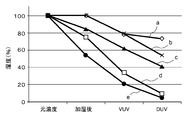
- Example 10 The result of the deodorization treatment was investigated using the light deodorization apparatus 100A shown in FIG. 1 as a parameter based on the humidity after humidification of the gas containing the off-flavor causing substance based on the light deodorization method shown in FIG. The result is shown in FIG.
- the cause of off-flavor was ammonia (NH 3 ).
- the vertical axis corresponds to the ammonia amount (NH 3 amount)
- the horizontal axis corresponds to each step in the photodeodorization method.
- NH 3 amount on the ordinate are NH 3 amount obtained by normalizing the NH 3 amount in the NH 3 containing gas before humidification as reference (100%).
- the amount of NH 3 further decreases after irradiation with VUV light.
- the gas humidity is 42% or more (c, d, e)
- the NH 3 amount of the treated gas after the DUV light irradiation is less than half of the original concentration.
- the reduction result of NH 3 in the processed gas is close to a saturated state.
- the gas humidity 50% or more, it was confirmed that can reduce the NH 3 until saturation.
- ammonia as a causative substance of a bad odor is shown, but the present invention is not limited to this.
- the offending odor causing substance may be any substance that decomposes by reacting with OH radicals.
Landscapes
- Health & Medical Sciences (AREA)
- Epidemiology (AREA)
- Life Sciences & Earth Sciences (AREA)
- Animal Behavior & Ethology (AREA)
- General Health & Medical Sciences (AREA)
- Public Health (AREA)
- Veterinary Medicine (AREA)
- Disinfection, Sterilisation Or Deodorisation Of Air (AREA)
Applications Claiming Priority (2)
| Application Number | Priority Date | Filing Date | Title |
|---|---|---|---|
| JP2018-070921 | 2018-04-02 | ||
| JP2018070921A JP6680306B2 (ja) | 2018-04-02 | 2018-04-02 | 光脱臭方法および光脱臭装置 |
Publications (1)
| Publication Number | Publication Date |
|---|---|
| WO2019194116A1 true WO2019194116A1 (ja) | 2019-10-10 |
Family
ID=68100800
Family Applications (1)
| Application Number | Title | Priority Date | Filing Date |
|---|---|---|---|
| PCT/JP2019/014435 Ceased WO2019194116A1 (ja) | 2018-04-02 | 2019-04-01 | 光脱臭方法および光脱臭装置 |
Country Status (2)
| Country | Link |
|---|---|
| JP (1) | JP6680306B2 (enExample) |
| WO (1) | WO2019194116A1 (enExample) |
Families Citing this family (5)
| Publication number | Priority date | Publication date | Assignee | Title |
|---|---|---|---|---|
| JP7048700B1 (ja) | 2020-10-28 | 2022-04-05 | 稔 浜田 | 空気浄化装置 |
| JP2023098527A (ja) * | 2021-12-28 | 2023-07-10 | キヤノン株式会社 | 気体処理装置、及び気体処理方法 |
| JP2023098525A (ja) * | 2021-12-28 | 2023-07-10 | キヤノン株式会社 | 活性酸素供給装置、活性酸素による処理装置及び活性酸素による処理方法 |
| WO2023127836A1 (ja) * | 2021-12-28 | 2023-07-06 | キヤノン株式会社 | 気体処理装置、及び気体処理方法 |
| JP2023170799A (ja) * | 2022-05-20 | 2023-12-01 | ウシオ電機株式会社 | 脱臭装置 |
Citations (6)
| Publication number | Priority date | Publication date | Assignee | Title |
|---|---|---|---|---|
| JPH04243596A (ja) * | 1991-01-24 | 1992-08-31 | Mitsubishi Electric Corp | 流体処理装置 |
| JPH06335518A (ja) * | 1993-05-31 | 1994-12-06 | Isuzu Motors Ltd | 発生期酸素発生装置 |
| JP2005331199A (ja) * | 2004-05-21 | 2005-12-02 | Matsushita Electric Ind Co Ltd | 冷蔵庫 |
| WO2008127315A2 (en) * | 2006-11-21 | 2008-10-23 | Primaira, Llc | Apparatus and method for treating impurities in air and materials |
| CN202933264U (zh) * | 2012-10-31 | 2013-05-15 | 北京伟通宝环境技术有限公司 | 室内恶臭气体消除装置 |
| JP2016094547A (ja) * | 2014-11-14 | 2016-05-26 | 株式会社カネカ | 樹脂組成物および成型体 |
-
2018
- 2018-04-02 JP JP2018070921A patent/JP6680306B2/ja not_active Expired - Fee Related
-
2019
- 2019-04-01 WO PCT/JP2019/014435 patent/WO2019194116A1/ja not_active Ceased
Patent Citations (6)
| Publication number | Priority date | Publication date | Assignee | Title |
|---|---|---|---|---|
| JPH04243596A (ja) * | 1991-01-24 | 1992-08-31 | Mitsubishi Electric Corp | 流体処理装置 |
| JPH06335518A (ja) * | 1993-05-31 | 1994-12-06 | Isuzu Motors Ltd | 発生期酸素発生装置 |
| JP2005331199A (ja) * | 2004-05-21 | 2005-12-02 | Matsushita Electric Ind Co Ltd | 冷蔵庫 |
| WO2008127315A2 (en) * | 2006-11-21 | 2008-10-23 | Primaira, Llc | Apparatus and method for treating impurities in air and materials |
| CN202933264U (zh) * | 2012-10-31 | 2013-05-15 | 北京伟通宝环境技术有限公司 | 室内恶臭气体消除装置 |
| JP2016094547A (ja) * | 2014-11-14 | 2016-05-26 | 株式会社カネカ | 樹脂組成物および成型体 |
Also Published As
| Publication number | Publication date |
|---|---|
| JP2019180472A (ja) | 2019-10-24 |
| JP6680306B2 (ja) | 2020-04-15 |
Similar Documents
| Publication | Publication Date | Title |
|---|---|---|
| WO2019194116A1 (ja) | 光脱臭方法および光脱臭装置 | |
| KR102164945B1 (ko) | 플라즈마와 광촉매를 이용한 공기 살균탈취장치 | |
| KR102160799B1 (ko) | 플라즈마를 이용한 출입관리 시스템 | |
| JP6453572B2 (ja) | 紫外線照射装置 | |
| JP2007518954A (ja) | オゾンで強化した過酸化水素蒸気汚染除去方法およびシステム | |
| JP5065132B2 (ja) | 除菌消臭ユニット及び除菌消臭機能付き暖房装置 | |
| JP6841631B2 (ja) | 紫外線照射装置 | |
| JP5229493B2 (ja) | 脱臭装置 | |
| JP2013153897A (ja) | 空気清浄機 | |
| KR20210047548A (ko) | 오존 및 oh 라디칼을 이용한 축사용 공기정화 시스템 | |
| KR20110127373A (ko) | 습한 오존과 공기 와류 생성을 이용한 공기살균장치 및 공기살균방법 | |
| WO2019082703A1 (ja) | 光脱臭装置および光脱臭方法 | |
| KR20110004617A (ko) | 고도산화공정을 이용한 고효율 탈취ㆍ공기살균 장치 및 그방법 | |
| KR101793497B1 (ko) | 유기성 폐기물 처리장 악취 제거장치 | |
| WO2007026050A1 (en) | Air disinfection device | |
| JP2004099205A (ja) | エレベーター装置 | |
| JP2016022231A (ja) | 空間等脱臭殺菌装置 | |
| JPH1057465A (ja) | オゾン水脱臭方法及び脱臭装置 | |
| KR20030085698A (ko) | 오존을 이용한 공기청정 탈취 살균기 | |
| CN114901319A (zh) | 气体处理方法、保存库、培养箱、灭菌器 | |
| JP5409978B1 (ja) | 二酸化塩素ガス処理構造、二酸化塩素ガス処理装置、滅菌装置および環境浄化装置 | |
| KR102285193B1 (ko) | 빌트인 타입 스마트 공기정화기 | |
| WO2020262478A1 (ja) | 気体処理方法、気体処理装置 | |
| JP2004166742A (ja) | オゾン薫蒸装置 | |
| JP2019076481A5 (enExample) |
Legal Events
| Date | Code | Title | Description |
|---|---|---|---|
| 121 | Ep: the epo has been informed by wipo that ep was designated in this application |
Ref document number: 19780516 Country of ref document: EP Kind code of ref document: A1 |
|
| NENP | Non-entry into the national phase |
Ref country code: DE |
|
| 122 | Ep: pct application non-entry in european phase |
Ref document number: 19780516 Country of ref document: EP Kind code of ref document: A1 |