WO2019194103A1 - 飛行機の突風応答軽減システム、乱気流検知システム、動揺推定システム、ドップラーライダー及び飛行機の突風応答軽減方法 - Google Patents
飛行機の突風応答軽減システム、乱気流検知システム、動揺推定システム、ドップラーライダー及び飛行機の突風応答軽減方法 Download PDFInfo
- Publication number
- WO2019194103A1 WO2019194103A1 PCT/JP2019/014210 JP2019014210W WO2019194103A1 WO 2019194103 A1 WO2019194103 A1 WO 2019194103A1 JP 2019014210 W JP2019014210 W JP 2019014210W WO 2019194103 A1 WO2019194103 A1 WO 2019194103A1
- Authority
- WO
- WIPO (PCT)
- Prior art keywords
- aircraft
- airplane
- lift
- turbulence
- wind speed
- Prior art date
- Legal status (The legal status is an assumption and is not a legal conclusion. Google has not performed a legal analysis and makes no representation as to the accuracy of the status listed.)
- Ceased
Links
Images


Classifications
-
- B—PERFORMING OPERATIONS; TRANSPORTING
- B64—AIRCRAFT; AVIATION; COSMONAUTICS
- B64C—AEROPLANES; HELICOPTERS
- B64C9/00—Adjustable control surfaces or members, e.g. rudders
-
- B—PERFORMING OPERATIONS; TRANSPORTING
- B64—AIRCRAFT; AVIATION; COSMONAUTICS
- B64C—AEROPLANES; HELICOPTERS
- B64C13/00—Control systems or transmitting systems for actuating flying-control surfaces, lift-increasing flaps, air brakes, or spoilers
- B64C13/02—Initiating means
- B64C13/16—Initiating means actuated automatically, e.g. responsive to gust detectors
-
- B—PERFORMING OPERATIONS; TRANSPORTING
- B64—AIRCRAFT; AVIATION; COSMONAUTICS
- B64D—EQUIPMENT FOR FITTING IN OR TO AIRCRAFT; FLIGHT SUITS; PARACHUTES; ARRANGEMENT OR MOUNTING OF POWER PLANTS OR PROPULSION TRANSMISSIONS IN AIRCRAFT
- B64D45/00—Aircraft indicators or protectors not otherwise provided for
-
- G—PHYSICS
- G01—MEASURING; TESTING
- G01P—MEASURING LINEAR OR ANGULAR SPEED, ACCELERATION, DECELERATION, OR SHOCK; INDICATING PRESENCE, ABSENCE, OR DIRECTION, OF MOVEMENT
- G01P5/00—Measuring speed of fluids, e.g. of air stream; Measuring speed of bodies relative to fluids, e.g. of ship, of aircraft
- G01P5/26—Measuring speed of fluids, e.g. of air stream; Measuring speed of bodies relative to fluids, e.g. of ship, of aircraft by measuring the direct influence of the streaming fluid on the properties of a detecting optical wave
-
- G—PHYSICS
- G05—CONTROLLING; REGULATING
- G05D—SYSTEMS FOR CONTROLLING OR REGULATING NON-ELECTRIC VARIABLES
- G05D1/00—Control of position, course, altitude or attitude of land, water, air or space vehicles, e.g. using automatic pilots
- G05D1/10—Simultaneous control of position or course in three dimensions
- G05D1/101—Simultaneous control of position or course in three dimensions specially adapted for aircraft
- G05D1/106—Change initiated in response to external conditions, e.g. avoidance of elevated terrain or of no-fly zones
-
- G—PHYSICS
- G01—MEASURING; TESTING
- G01S—RADIO DIRECTION-FINDING; RADIO NAVIGATION; DETERMINING DISTANCE OR VELOCITY BY USE OF RADIO WAVES; LOCATING OR PRESENCE-DETECTING BY USE OF THE REFLECTION OR RERADIATION OF RADIO WAVES; ANALOGOUS ARRANGEMENTS USING OTHER WAVES
- G01S13/00—Systems using the reflection or reradiation of radio waves, e.g. radar systems; Analogous systems using reflection or reradiation of waves whose nature or wavelength is irrelevant or unspecified
- G01S13/02—Systems using reflection of radio waves, e.g. primary radar systems; Analogous systems
- G01S13/06—Systems determining position data of a target
- G01S13/08—Systems for measuring distance only
- G01S13/10—Systems for measuring distance only using transmission of interrupted, pulse modulated waves
- G01S13/18—Systems for measuring distance only using transmission of interrupted, pulse modulated waves wherein range gates are used
-
- G—PHYSICS
- G01—MEASURING; TESTING
- G01S—RADIO DIRECTION-FINDING; RADIO NAVIGATION; DETERMINING DISTANCE OR VELOCITY BY USE OF RADIO WAVES; LOCATING OR PRESENCE-DETECTING BY USE OF THE REFLECTION OR RERADIATION OF RADIO WAVES; ANALOGOUS ARRANGEMENTS USING OTHER WAVES
- G01S13/00—Systems using the reflection or reradiation of radio waves, e.g. radar systems; Analogous systems using reflection or reradiation of waves whose nature or wavelength is irrelevant or unspecified
- G01S13/02—Systems using reflection of radio waves, e.g. primary radar systems; Analogous systems
- G01S13/50—Systems of measurement based on relative movement of target
- G01S13/52—Discriminating between fixed and moving objects or between objects moving at different speeds
-
- G—PHYSICS
- G01—MEASURING; TESTING
- G01S—RADIO DIRECTION-FINDING; RADIO NAVIGATION; DETERMINING DISTANCE OR VELOCITY BY USE OF RADIO WAVES; LOCATING OR PRESENCE-DETECTING BY USE OF THE REFLECTION OR RERADIATION OF RADIO WAVES; ANALOGOUS ARRANGEMENTS USING OTHER WAVES
- G01S13/00—Systems using the reflection or reradiation of radio waves, e.g. radar systems; Analogous systems using reflection or reradiation of waves whose nature or wavelength is irrelevant or unspecified
- G01S13/88—Radar or analogous systems specially adapted for specific applications
- G01S13/95—Radar or analogous systems specially adapted for specific applications for meteorological use
- G01S13/953—Radar or analogous systems specially adapted for specific applications for meteorological use mounted on aircraft
-
- G—PHYSICS
- G01—MEASURING; TESTING
- G01S—RADIO DIRECTION-FINDING; RADIO NAVIGATION; DETERMINING DISTANCE OR VELOCITY BY USE OF RADIO WAVES; LOCATING OR PRESENCE-DETECTING BY USE OF THE REFLECTION OR RERADIATION OF RADIO WAVES; ANALOGOUS ARRANGEMENTS USING OTHER WAVES
- G01S17/00—Systems using the reflection or reradiation of electromagnetic waves other than radio waves, e.g. lidar systems
- G01S17/02—Systems using the reflection of electromagnetic waves other than radio waves
- G01S17/50—Systems of measurement based on relative movement of target
- G01S17/58—Velocity or trajectory determination systems; Sense-of-movement determination systems
-
- G—PHYSICS
- G01—MEASURING; TESTING
- G01S—RADIO DIRECTION-FINDING; RADIO NAVIGATION; DETERMINING DISTANCE OR VELOCITY BY USE OF RADIO WAVES; LOCATING OR PRESENCE-DETECTING BY USE OF THE REFLECTION OR RERADIATION OF RADIO WAVES; ANALOGOUS ARRANGEMENTS USING OTHER WAVES
- G01S17/00—Systems using the reflection or reradiation of electromagnetic waves other than radio waves, e.g. lidar systems
- G01S17/87—Combinations of systems using electromagnetic waves other than radio waves
-
- G—PHYSICS
- G01—MEASURING; TESTING
- G01S—RADIO DIRECTION-FINDING; RADIO NAVIGATION; DETERMINING DISTANCE OR VELOCITY BY USE OF RADIO WAVES; LOCATING OR PRESENCE-DETECTING BY USE OF THE REFLECTION OR RERADIATION OF RADIO WAVES; ANALOGOUS ARRANGEMENTS USING OTHER WAVES
- G01S17/00—Systems using the reflection or reradiation of electromagnetic waves other than radio waves, e.g. lidar systems
- G01S17/88—Lidar systems specially adapted for specific applications
- G01S17/95—Lidar systems specially adapted for specific applications for meteorological use
-
- G—PHYSICS
- G01—MEASURING; TESTING
- G01S—RADIO DIRECTION-FINDING; RADIO NAVIGATION; DETERMINING DISTANCE OR VELOCITY BY USE OF RADIO WAVES; LOCATING OR PRESENCE-DETECTING BY USE OF THE REFLECTION OR RERADIATION OF RADIO WAVES; ANALOGOUS ARRANGEMENTS USING OTHER WAVES
- G01S7/00—Details of systems according to groups G01S13/00, G01S15/00, G01S17/00
- G01S7/48—Details of systems according to groups G01S13/00, G01S15/00, G01S17/00 of systems according to group G01S17/00
- G01S7/481—Constructional features, e.g. arrangements of optical elements
- G01S7/4817—Constructional features, e.g. arrangements of optical elements relating to scanning
-
- G—PHYSICS
- G01—MEASURING; TESTING
- G01W—METEOROLOGY
- G01W1/00—Meteorology
- G01W2001/003—Clear air turbulence detection or forecasting, e.g. for aircrafts
-
- Y—GENERAL TAGGING OF NEW TECHNOLOGICAL DEVELOPMENTS; GENERAL TAGGING OF CROSS-SECTIONAL TECHNOLOGIES SPANNING OVER SEVERAL SECTIONS OF THE IPC; TECHNICAL SUBJECTS COVERED BY FORMER USPC CROSS-REFERENCE ART COLLECTIONS [XRACs] AND DIGESTS
- Y02—TECHNOLOGIES OR APPLICATIONS FOR MITIGATION OR ADAPTATION AGAINST CLIMATE CHANGE
- Y02T—CLIMATE CHANGE MITIGATION TECHNOLOGIES RELATED TO TRANSPORTATION
- Y02T50/00—Aeronautics or air transport
- Y02T50/30—Wing lift efficiency
-
- Y—GENERAL TAGGING OF NEW TECHNOLOGICAL DEVELOPMENTS; GENERAL TAGGING OF CROSS-SECTIONAL TECHNOLOGIES SPANNING OVER SEVERAL SECTIONS OF THE IPC; TECHNICAL SUBJECTS COVERED BY FORMER USPC CROSS-REFERENCE ART COLLECTIONS [XRACs] AND DIGESTS
- Y02—TECHNOLOGIES OR APPLICATIONS FOR MITIGATION OR ADAPTATION AGAINST CLIMATE CHANGE
- Y02T—CLIMATE CHANGE MITIGATION TECHNOLOGIES RELATED TO TRANSPORTATION
- Y02T50/00—Aeronautics or air transport
- Y02T50/40—Weight reduction
Definitions
- the present invention relates to a gust response mitigation system and method used to reduce vertical motion of an airframe when an airplane flies in turbulence, for example, a turbulence detection system suitable for use in these techniques, and sway estimation. System and Doppler rider.
- Turbulence is particularly important as a major cause of passenger aircraft accidents, and technology relating to Doppler lidar using laser light has been researched and developed as a device for detecting turbulence in advance by being mounted on an aircraft (for example, see Non-Patent Document 1). reference.).
- Patent Document 3 a remote airflow measurement device, a remote airflow measurement method, and a remote airflow measurement method that can improve the estimation accuracy of a two-dimensional airflow vector including a vertical airflow vector and can further widen the airflow estimation range. advocated the program.
- the measurement accuracy of the optical axis in the line-of-sight direction is 0.2 to 0.3 m / s based on the results of Monte Carlo simulation.
- the estimation accuracy is 0.6 to 0.9 m / s when the scissor angle is 20 degrees.
- this is only a geometric estimation calculation, and in reality, there is a possibility that the error will increase due to the influence of a complicated local flow.
- the present invention solves the above-mentioned problems, and its purpose is to provide a technique for reducing the fluctuation of the airframe when an airplane enters a turbulent air flow without using prior information of air flow vectors of two or more dimensions. There is to do.
- an airplane gust response mitigation system radiates electromagnetic waves toward a flight direction of an airplane, receives scattered waves in the atmosphere, and radiates the emitted electromagnetic waves. Based on the Doppler shift amount of the frequency between the scattered electromagnetic wave and the scattered electromagnetic wave, the measurement unit for measuring the remote wind speed in the radial axis direction, the rudder for controlling the lift of the aircraft, and the measurement result in the measurement unit, And a control calculation unit that calculates an angle of attack with a small lift inclination and a rudder angle for controlling the lift so that the lift does not change.
- An aircraft gust response mitigation method radiates an electromagnetic wave toward a flight direction of an airplane, receives a scattered wave in the atmosphere, and between the radiated electromagnetic wave and the scattered electromagnetic wave.
- the remote wind speed in the radial axis direction is measured based on the amount of Doppler shift of the frequency, and when it is found that the airplane receives a gust wind based on the measurement result, the angle of attack with a small lift inclination is calculated and the lift force
- the rudder angle of the aircraft that controls the lift force so that does not change is calculated.
- a turbulence detection system radiates an electromagnetic wave toward a flight direction of an airplane, receives a scattered wave in the atmosphere, and has a frequency between the radiated electromagnetic wave and the scattered electromagnetic wave.
- a measurement unit that measures the remote wind speed in the radial axis direction based on the Doppler shift amount, and a control calculation unit that calculates an intensity index of turbulence in the planned flight direction of the airplane based on the measurement result of the measurement unit,
- the control calculation unit uses the product of the amount of change in the wind speed in the radial axis direction of the radiated electromagnetic wave, the flight speed, and the air density or static pressure as the turbulence intensity index.
- the control calculation unit obtains the wind speed width in the range bin from the amount of increase in the power spectrum width of the scattering in the range bin as the amount of change in the wind speed in the radial axis direction, and expresses the intensity of the turbulence numerically by the wind speed width. Good.
- the motion estimation system radiates electromagnetic waves in the planned flight direction of an airplane, receives scattered waves in the atmosphere, and has a frequency between the radiated electromagnetic waves and the scattered electromagnetic waves.
- a control unit that measures a remote wind speed in the radial axis direction based on a Doppler shift amount; and a control calculation unit that calculates an index of the degree to which the airplane shakes based on a measurement result of the measurement unit, the control calculation unit Uses the value of the maximum acceleration that continues for a certain period of time as an indicator of the degree to which the airplane shakes, by removing the high and low components of the shaking frequency.
- a Doppler lidar emits a light wave toward a flight direction of an airplane, receives a scattered wave in the atmosphere, and has a frequency Doppler between the emitted light wave and the scattered light wave.
- a measurement unit that measures the remote wind speed in the radial direction based on the shift amount, and a scanner that changes the direction of the light wave and has a condensing function of an optical telescope.
- FIG. 1 is a block diagram showing a configuration of a Doppler lidar gust response mitigation system mounted on an airplane according to an embodiment of the present invention. It is explanatory drawing which shows the method of expanding the measurement range of the wind speed which concerns on one Embodiment of this invention. It is explanatory drawing which shows the effect of the method of calculating the approximate value of the true air speed which concerns on one Embodiment of this invention.
- the aircraft gust response mitigation system radiates electromagnetic waves toward the flight direction of the aircraft, receives scattered waves in the atmosphere, and has a frequency between the emitted electromagnetic waves and the scattered electromagnetic waves. Based on the Doppler shift amount, the measurement unit that measures the remote wind speed in the radial axis direction, the rudder that controls the lift of the aircraft, and the measurement result of the measurement unit, when it is found that the aircraft receives a gust of wind And a control calculation unit that calculates an angle of attack with a small lift inclination and calculates an angle of a rudder that controls the lift so that the lift does not change.
- FIG. 1 shows a case where a gust of wind is encountered during flight.
- the relative wind vector of the gust to the airplane 200 is W
- its vertical component is W Z
- its front and rear components are W X
- the angle of attack ⁇ ′ when encountering a gust can be obtained by the following equation.
- ⁇ ′ ⁇ + tan ⁇ 1 (W Z / (V + W Z )) (2)
- Equation 2 can be simplified as the following equation.
- ⁇ ′ ⁇ + W Z / V (3) Therefore, when the lift change due to the gust changing the angle of attack is ⁇ L, it can be obtained by the following equation.
- ⁇ L ⁇ VW Z S (4) That is, it can be said that the lift change ⁇ L caused by the change in the angle of attack caused by the gust of wind is substantially proportional to the product of the air density ⁇ , the flight speed V, and the vertical component W Z of the gust of wind.
- ⁇ L ⁇ C L S (VW X + (1/2) W X 2 ) (6)
- the turbulent airflow is considered to be isotropic, it can be said that the vertical fluctuation of the airplane due to the turbulent airflow is substantially proportional to the product of the air density ⁇ , the flight speed V, and the gust W. Therefore, it is appropriate to use these products ⁇ VW as the turbulence intensity index. Although there is some variation in isotropy, it is generally considered that there is a correlation.
- As a method for expressing the product of the flight speed V and the gust W there is an Fh factor (Patent Document 4).
- the gust W the wind speed dispersion value indicated by the spectrum width of the received light in the observation region is used. Also good.
- the air density [rho, proportional to the static pressure P S measured by the static pressure hole for determining the pressure altitude, the strength index of the turbulence may use P S VW.
- Static pressure P S or air density ⁇ and flight speed V is measured by the Pitot-static tube which has been installed on all aircraft.
- the flight speed V and the front gust W can be measured by, for example, a Doppler rider. Therefore, in the gust response mitigation system of the present invention, for example, laser light is emitted (transmitted) into the atmosphere as a transmission signal, laser scattered light from the aerosol in the atmosphere of the laser light is received as a reception signal, and the transmission is performed.
- a Doppler rider that measures the wind speed of the airflow in the remote area based on the Doppler shift amount of the frequency between the signal and the received signal, the gust of wind ahead is observed, and the fluctuation of the airframe is reduced by the automatic control of the rudder .
- FIG. 2 is a conceptual diagram showing a general airfoil lift curve, in which point S is referred to as a stall point, area A is referred to as a front side, and area B is referred to as a back side.
- point S is referred to as a stall point
- area A is referred to as a front side
- area B is referred to as a back side.
- the region A when the pilot pulls the control stick, the posture is turned upward, and the lift is increased in a short time, so that the aircraft is raised. This is a natural behavior for human senses.
- the flying speed decreases and the lift decreases, and the aircraft descends.
- the present invention describes the reduction of shaking, only a short-time motion is considered.
- the engine output may be adjusted by normal operation.
- the control stick In the region B, contrary to the region A, if the control stick is pulled, the lift decreases and the aircraft descends, so special attention is required when maneuvering. Usually, the control stick is pushed to return to the area A. It is not necessarily a dangerous area, and may be actively used in power drift machines.
- the lift coefficient changes little with respect to the angle of attack, and even if the vertical wind changes, the lift does not change so much that the vertical movement of the aircraft is suppressed.
- the angle of attack is increased in order to shift to the point S when flying in the A region, the aircraft will rise, so it is necessary to appropriately control the lift force in order to maintain level flight. is there.
- a flaperone that changes the left and right ailerons in phase may be used, or both may be used in combination.
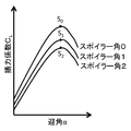
- FIG. 3 schematically shows how the lift coefficient changes depending on the change in the spoiler angle.
- the lift coefficient decreases and the lift change near the S point decreases.
- the aircraft because lift is increased when increasing the angle of attack attempts to fly at S 0 point rises.
- the lift coefficient is to deploy the spoiler to be two points S, actually increases the drag with an increase in angle of attack, and reduced lift for the flying speed is reduced flight Altitude decreases.
- the aircraft normally flies at the most efficient angle of attack with the highest lift-drag ratio, so if the angle of attack is changed, horizontal flight may not be possible with the same thrust. Approaches gradually S 0 point with S 1 point of time, eventually if spoiler angle comes to drop even becomes 0, it is necessary to increase the thrust before the spoiler angle is zero.
- the thrust increasing operation may be automatic or manual. It is usually included in the autopilot function.
- the change in lift due to the change in the front and rear winds will offset the change in lift by changing the spoiler angle according to the measurement value of the front and rear winds in front of the aircraft. Since it is quasi-static control for changes in vertical wind and dynamic control for changes in front and rear winds, it is possible to achieve both.
- the control that cancels the change in the lift due to the front and rear winds is typically directly controlled by a spoiler installed on the main wing that generates the lift, and thus is less susceptible to the elastic deformation of the airframe. This is an advantage greatly different from the lift control by the control of the elevator.
- the range of wind speed that can be observed is limited. For this reason, when mounted on an airplane and used, a method of subtracting the flight speed and measuring the change from the subtracted speed is taken.
- the average value of the immediately preceding observation value is regarded as the flight speed.
- the observation value may include an abnormal value, and thus the average value may be inconvenient. I understood.
- the mode (mode) of the immediately preceding observation value is regarded as the flight speed.
- the flight speed In order to calculate the mode, it is necessary to divide the observation value in a finite wind speed range and generate a histogram, so the resolution of the flight speed measurement value depends on the division width of the wind speed. However, the flight speed may be approximate because it is only necessary to be within the wind speed observable range.
- the vertical attitude angle of the aircraft generally changes. Since the change in the vertical attitude angle causes vertical acceleration depending on the position of the airplane in the cabin, the aircraft gust response mitigation system according to one aspect of the present invention moves up and down to reduce the vertical angular acceleration. A function of controlling the rudder may be added.
- the aircraft gust response mitigation system adds a control function for preventing an accident by making a turn flight and superimposing the acceleration due to the centrifugal force on the gravitational acceleration when entering the turbulence. Also good.
- the aircraft gust response mitigation system has a control function that automatically interrupts the altitude change when a front turbulence layer is detected during altitude change in order to prevent entry into the turbulence layer. It may be added.
- the Doppler lidar used in the present invention can observe very weak air currents, but observation errors cannot be avoided. For this reason, there is a possibility of outputting a signal as if there is a slight change in air flow when there is no turbulent air flow, in which case the airframe may be vibrated. Furthermore, since the flight speed is lowered in the control according to the present invention, the operation efficiency is lowered during the operation of the control. Therefore, there is a need for a criterion that the lift control is not performed when the intensity of the observed turbulence is low, and the lift control is performed when the intensity is above a certain threshold. In the aircraft gust response reduction system according to an embodiment of the present invention, the above-described ⁇ VW or P S VW is used as the turbulence intensity index.
- the strength of turbulence can be defined by the above indicators, but the degree of airplane sway varies depending on the aerodynamic characteristics and inertial force of each aircraft. Therefore, in order to determine the danger, it is necessary to define the degree to which the airplane shakes.
- the components of the high frequency fluctuation and the low frequency fluctuation which are less likely to be related to the turbulence accident are excluded, and the value of the maximum acceleration continuous for a certain period of time is excluded. Used as an indicator of the degree of shaking.
- the correspondence between the turbulence intensity index on individual airplanes and the turbulence degree index may be clarified by flight simulation or flight test. That is, the intensity index of the turbulence at the time of the level fluctuation that does not require control or the level that requires emergency response may be examined and reflected in the control law.
- the scanner that changes the direction of the light wave has the light condensing function of the optical telescope, which makes it smaller and lighter.
- the scanner may be a convex prism type or a concave mirror type.
- the present invention even when a monocular rider is used, when the airplane encounters turbulence, it is possible to reduce the up and down motion of the aircraft, and it can be expected to improve the safety and comfort of the airplane.
- Non-Patent Document 3 Airworthiness Examination Guidelines Part III 7-2-6B shown in Non-Patent Document 3 defines the maximum speed for entering turbulent airflow.
- Currently when flying in an airspace where turbulent airflow may occur, although there is a case where it is necessary to decelerate, according to the present invention, it is only necessary to decelerate when turbulence is detected, so that it is possible to expect improvement in operational efficiency and punctuality.
- FIG. 4 is a block diagram showing a configuration of a gust response mitigation system mounted on an airplane according to an embodiment of the present invention.
- the control command generation unit 100 of the airplane gust response reduction system includes a measurement unit 10 and a control calculation unit 30.
- the scanner 300 is a component for changing the radiation direction of laser light, but is not a component essential for the implementation of the present invention. This is because the angle of attack and side slip angle of an airplane during cruising do not change greatly, and the application of the present invention is limited only to dealing with turbulent airflow in the short distance, the observation area does not change significantly. It is.
- the measurement unit 10 radiates laser light into the atmosphere in the form of pulses, receives the reflected light, and based on the Doppler shift amount of the frequency between the emitted laser light and reflected light, the optical axis direction (radiation axis direction)
- the optical telescope 11, the optical transceiver 12, and the signal processing unit 13 are included.
- the optical telescope 11 radiates laser light (transmitted light) generated by the optical transceiver 12 toward the atmosphere.
- the emitted laser light is scattered by minute aerosol particles floating in the atmosphere.
- the scattered light is received by the optical transceiver 12 via the optical telescope 11.
- the optical transceiver 12 generates laser light having a single wavelength, for example, 1.5 ⁇ m, receives scattered light in the atmosphere, and electrically calculates the frequency difference between the emitted laser light and the scattered light. Convert to signal.
- the signal processing unit 13 time-divides the frequency difference signal to calculate the wind speed for each distance. That is, the received light (scattered light) received through the optical telescope 11 is compared with the transmitted light, and the wind speed is obtained from the change in frequency caused by the Doppler effect.
- the amount of frequency change due to the Doppler effect is typically used to measure wind speed. In general, this is called a Doppler rider, and a rider (LIDAR) is a remote observation technique using light, which is an abbreviation of “Light Detection And Ranging”.
- the maximum observation distance is about 1 to 30 km, and this value varies depending on atmospheric conditions. For ordinary passenger aircraft, this distance corresponds to a flight distance of 4 to 150 seconds.
- the approximate value of the true airspeed is used as an offset as shown in FIG.
- the Doppler shift amount of the frequency is F OFST + F d .
- the measurable range of the wind speed with the prototype device is ⁇ 40 m / s.
- the average value of the immediately preceding observation values is regarded as the true air speed.
- the observation value may include an abnormal value, FIG. As shown in the figure, it was found that the average value may have a large error.
- the mode (mode) of the observed value 1 to 3 seconds before is regarded as the true airspeed.
- the mode (mode) may be calculated only for an observation range with high reliability such as an SN ratio of the received signal of, for example, 7 dB or more.
- the mode In order to calculate the mode (mode), it is necessary to divide the observed values in a finite wind speed range and generate a histogram, so the resolution of the true airspeed measurement value depends on the division width of the wind speed become. Since the wind speed division width is suitably 2 to 5 m / s, the resolution is also the numerical value. However, since it is only necessary to enter the wind speed observable range, the true airspeed may be an approximate value with low resolution.
- abnormal values exceeding 1 ⁇ are excluded from the histogram of the latest observed values based on the standard deviation, and normal observations are performed. If an average value of only values is obtained, a true airspeed with high reliability and accuracy can be obtained. If static pressure information is used, it is possible to convert the true airspeed into an equivalent airspeed.
- control calculation unit 30 determines the steering angle of the elevator 231 so that the angle of attack of the lift 231 is small when it is found that the airplane 200 receives a gust of wind. A command is transmitted to the autopilot 210. The steering angle changes slowly, and the angle of attack is fed back to set the target angle of attack. In addition, a steering angle command of the spoiler 221 that does not change the lift is transmitted to the autopilot 210.
- the angle of attack with the smallest lift inclination is the angle of attack at which the lift coefficient becomes the maximum value, and the angle of attack can be obtained by a wind tunnel test as shown in Non-Patent Document 2, for example.
- the lift coefficient 3-10 seconds before encountering turbulence is operated automatically and slowly the elevator 231 toward the angle of attack of maximum value, aircraft temporarily And the flight speed decreases.
- the lift rate is fed back and the rudder angle of the spoiler 221 is appropriately increased, the lift and weight are balanced and the lift rate becomes zero.
- the flying speed further decreases with time and the lift decreases.
- the lift rate remains zero.
- the spoiler 221 may descend even if the rudder angle of the spoiler 221 becomes zero, but before that, the thrust is increased to maintain the horizontal flight.
- the vehicle may descend if it is in a situation that allows the vehicle to descend.
- the rudder that controls the lift may be a flaperon instead of a spoiler. Alternatively, it may be a dedicated rudder for reducing shaking or a flap that operates at high speed. A plurality of rudders may be used in combination.
- the steering angle is controlled based on the output of the acceleration sensor that is usually attached to the aircraft.
- the acceleration sensor that is usually attached to the aircraft.
- a rudder angle command is transmitted to the rudder actuator, but there is a delay until the rudder aerodynamic force is changed.
- the rudder can be controlled in advance in consideration of the delay, so the influence of the average delay does not occur, and the remote airflow observation error and Only slight effects such as rudder angle error remain. Therefore, since it can cope with fine shaking with high frequency, not only the reduction of accidents but also improvement of riding comfort can be expected.
- the vertical moment coefficient Cm may slightly change. Consequently pitching occurs, it will cause to produce vertical acceleration proportional to the angular acceleration in accordance with the position of the room of the airplane, the change amount C m [delta] SP of C m corresponding to the pre-spoiler angle, wind tunnel test It is better to change the elevator according to the spoiler angle.
- the characteristics of the C m change amount C m ⁇ SP according to the spoiler angle and the C m change amount C m ⁇ EL according to the elevator angle as shown in FIG. 9 are obtained in advance.
- As spoiler angles at a certain time is [delta] SP1
- a command of changing the spoiler angle [delta] SP2 amount was issued for the control according to the present invention
- C m changes by [delta] Cm the moment In order to cancel out
- the elevator angle at that time is ⁇ EL1
- a command for making the elevator angle to ⁇ EL2 for generating a reverse moment is issued simultaneously. Since the elevator angle control for changing the angle of attack according to the present invention is a quasi-static control and the elevator angle control for canceling the vertical moment is a dynamic control, both can be achieved.
- C m ⁇ SP may be obtained by a flight test.
- a conventional function of controlling the elevator by feeding back the signal of the angular acceleration sensor may be used.
- control calculation unit 30 may transmit a turning command to the autopilot 210 when turbulence ahead is detected. For example, when turning in a 30-degree bank that is permitted for normal passenger aircraft operation, the vertical acceleration increases by about 15%, so that the possibility of lifting personnel and articles can be reduced.
- the left and right turning directions may be determined, and turning flight may be performed to avoid the turbulence in a weak direction.
- the control calculation unit 30 may transmit a command to cancel the altitude change to the autopilot 210.
- the turbulence region is often distributed in a layered manner in the altitude direction, and when this is detected in advance by a Doppler rider, it is possible to avoid entering the turbulent layer if the altitude change is stopped. . The same is true whether it is rising or falling.
- the above-described ⁇ VW or P S VW is used as a turbulence intensity index.
- P S is easy to use because it is static pressure to use the barometric altimeter.
- W the wind speed change amount W.
- VW can be obtained by using the Fh-factor shown in “Method of detecting turbulence” in Patent Document 4.
- the Fh-factor calculates the difference between the two measurement values, so if one or both of the two measurement values are defective in measurement, an incorrect numerical value is calculated.
- the “remote turbulence detection method and apparatus for carrying it out” in Patent Document 7 uses the spectrum width of the received signal.
- an error occurs in the estimation of the wind speed width because the spectrum width of the transmission signal is not zero.
- the optical axis direction wind speed change amount W is obtained by subtracting the power spectrum width of the transmitted light from the power spectrum width of the scattered light received by the optical transceiver 12, that is, by scattering. It is assumed that the increase amount of the power spectrum width is proportional to the change amount of the wind speed in the optical axis direction. Therefore, the optical axis direction wind speed variation W (standard deviation of the wind speed in the range bin) is given by the following.
- W ⁇ (fdr ⁇ fdt) 2 (9)
- ⁇ is the wavelength of the laser light
- fdr is the power spectrum width of the received light
- fdt is the power spectrum width of the transmitted light. Since W is the standard deviation of the wind speed, it is proportional to the amount of change in wind speed.
- P s VW V may be a true airspeed value according to the present invention, or may be obtained from an airspeedometer normally mounted on an airplane.
- W is an airflow change that is less than the observation accuracy (for example, 0.22 m / s or less), there is a possibility that the control surface will vibrate in reverse, so it is more appropriate not to implement the control even if the airflow change is observed. It is. Alternatively, the control gain may be changed according to the observed airflow change amount.
- the strength of turbulence can be defined by the above indicators, but the degree of airplane sway varies depending on the aerodynamic characteristics and inertial force of each aircraft. Therefore, an indicator is also required to the extent that the airplane is shaken.
- a component having a high frequency of less than 2 Hz and a component having a low frequency of 0.1 Hz or less is excluded as a high frequency that is less likely to be related to a turbulence accident.
- the value of the maximum acceleration a that lasts for 0.3 seconds is used as an index of the degree of fluctuation of the airplane.
- the maximum acceleration a may be expressed in a logarithm.
- the correspondence between the turbulence intensity index on individual airplanes and the turbulence degree index may be clarified by flight simulation or flight test. That is, a correlation coefficient between the turbulence intensity index and the actually generated acceleration may be obtained to determine a threshold value that matches the human sense.
- a correlation coefficient between the turbulence intensity index and the actually generated acceleration may be obtained to determine a threshold value that matches the human sense.
- the aircraft motion index is calculated from the turbulence intensity index and the aircraft specifications (S5) (S6). If the aircraft motion index is less than the preset threshold, emergency avoidance such as turning or stopping altitude change is assumed as no urgency. Do not implement control. Aircraft specifications include airframe weight, flight speed, and aerodynamic data. If it is equal to or greater than the threshold, emergency avoidance control is performed (S7). If the altitude is being changed, an altitude change stop command is issued, and if the altitude is not being changed, a turn command is issued to the autopilot. Even when turbulence cannot be avoided in practice, the fluctuation reduction control according to the present invention and the superimposition of vertical acceleration by turning effectively act, and the accident can be reduced. Pilot judgment may be involved in emergency avoidance.
- the Doppler lidar receives extremely weak scattered light, the larger the aperture of the optical telescope 11, the better the performance.
- the prototype optical antenna 40 weighs about 50 kg
- the prism type scanner 301 for changing the direction of the optical axis weighs about 45 kg. It was. These were arranged at the front and back as shown in FIG. The left side of the figure is the nose direction.
- the chamber 242 is for pressurizing the optical antenna 40 in the same manner as in the apparatus, and light is emitted through the chamber window 243.
- the scanner 301 has double prisms that can be rotated by an electric motor, and can freely change the direction of light.
- the fairing window 241 is a window attached to the front surface of the fairing 240 that houses these devices.
- a large optical telescope having a diameter of 150 mm is disposed on the optical antenna, high rigidity is required, and it is difficult to reduce the weight structurally.
- the lens used for the optical telescope 11 requires extremely high optical characteristics, it cannot be reduced in weight by a Fresnel lens or the like.
- FIG. 14A shows a conventional configuration.
- the objective lens of the optical telescope 11 is omitted, and the prism of the scanner 302 is made convex so that the function of the objective lens is also used.
- the objective lens becomes unnecessary, not only the weight of the objective lens but also the structure supporting the objective lens becomes unnecessary, and the optical antenna casing itself can be reduced in size, so that the weight can be reduced.
- a fairing window 303 may be used as a convex lens so as to serve as an objective lens, and the small concave lens 304 may be moved to change the direction of the laser beam. At this time, a mechanism is adopted in which the optical axis of the laser is always directed toward the center of the fairing window 303.
- the fairing window 303 has a thickness of 2 cm or more because strength is required, and it is easy to make a convex lens.
- the fairing window 303 is located outside the scanner 300 so that the laser beam is not lost. There is no need to increase the size of the fairing window 303. The weight reduction effect of eliminating the need for the scanner 300 is also great.
- FIG. 3 An example of a specific mechanism for moving the small concave lens 304 is shown in FIG.
- the angle-of-attack changing support 311 is attached to the frame of the convex fairing window 303 so that the optical axis 310 always faces the center of the convex fairing window 303 even if the optical axis 310 changes in the elevation angle direction.
- the azimuth change can be realized by rotating the azimuth change support tool 312, and the optical transmission / reception unit 314 with the small concave lens 304 attached to the tip is fixed to the azimuth change support tool 312.
- the optical axis 310 always faces the center of the convex fairing window 303 because it moves laterally along the slit 311S.
- the optical fiber cable 315 is used for transmitting transmission / reception light, it is not suitable for high output light, but the structure becomes simple, and the optical transmission / reception unit is a non-pressurized part such as a radome outside the pressure partition 250 It becomes possible to arrange in. As a result, the chamber 242 and the chamber window 243 are not required (see FIG. 13).
- the output light diffused at the exit of the optical fiber cable 315 is first converted into parallel rays by a convex lens. Therefore, in order to diffuse the output light according to the aperture of the convex fairing window 303, the 304 becomes a concave lens.
- the convex lens and 304 may be integrated to form a convex lens.
- a concave mirror 305 can be used instead of an objective lens as shown in FIG. In order to change the optical axis, the concave mirror 305 may be rotated.
- the concave mirror 305 shown in FIG. 17 When the concave mirror 305 shown in FIG. 17 is rotated to change the direction of the laser beam, there is a need for a fairing dimension, so that the overhang outside the apparatus increases, and air resistance and aerodynamic noise may increase. . Therefore, the elevation (elevation angle) of the laser beam is changed by moving the small convex mirror 306 back and forth and rotating the small convex mirror 306 so that the optical axis faces the center of the concave mirror 305 as shown in FIG. It is good also as a mechanism to do. In order to change the azimuth (azimuth) of the laser beam, the concave mirror 305 may be configured to rotate in the azimuth direction.
- FIG. 19 shows an example of a specific mechanism for rotating the small convex mirror 306 simultaneously with the back-and-forth movement using the rack gear 307 and the reduction gear 308.
- the rack gear 307 is fixed to the airframe, and when the support 309 of the reduction gear 308 is moved back and forth, the small convex mirror 306 rotates.
- the gear ratio of the reduction gear 308 is appropriately set, it is possible to design the optical axis 310 so as to always face the center of the concave mirror 305. At this time, if fine adjustment of the angle change amount of the small convex mirror 306 is necessary, an elliptical gear may be used as the reduction gear 308.
- FIG. 20 shows an example of a specific mechanism for rotating the small convex mirror 306 simultaneously with the back and forth movement using a link mechanism.
- the gust response mitigation system of the present invention can be suitably applied as a means for reducing airframe fluctuation when an airplane encounters turbulence.
Landscapes
- Engineering & Computer Science (AREA)
- Aviation & Aerospace Engineering (AREA)
- Automation & Control Theory (AREA)
- Physics & Mathematics (AREA)
- General Physics & Mathematics (AREA)
- Radar, Positioning & Navigation (AREA)
- Remote Sensing (AREA)
- Multimedia (AREA)
- Optical Radar Systems And Details Thereof (AREA)
Priority Applications (2)
| Application Number | Priority Date | Filing Date | Title |
|---|---|---|---|
| EP19780631.8A EP3778386B1 (en) | 2018-04-04 | 2019-03-29 | Gust alleviation system and gust alleviation method of airplane |
| US17/043,427 US11827337B2 (en) | 2018-04-04 | 2019-03-29 | Gust alleviation system of airplane, turbulence detection system, fluctuation estimation system, doppler LIDAR, and gust alleviation method of airplane |
Applications Claiming Priority (2)
| Application Number | Priority Date | Filing Date | Title |
|---|---|---|---|
| JP2018072705A JP7097052B2 (ja) | 2018-04-04 | 2018-04-04 | 飛行機の突風応答軽減システム及び飛行機の突風応答軽減方法 |
| JP2018-072705 | 2018-04-04 |
Publications (1)
| Publication Number | Publication Date |
|---|---|
| WO2019194103A1 true WO2019194103A1 (ja) | 2019-10-10 |
Family
ID=68100361
Family Applications (1)
| Application Number | Title | Priority Date | Filing Date |
|---|---|---|---|
| PCT/JP2019/014210 Ceased WO2019194103A1 (ja) | 2018-04-04 | 2019-03-29 | 飛行機の突風応答軽減システム、乱気流検知システム、動揺推定システム、ドップラーライダー及び飛行機の突風応答軽減方法 |
Country Status (4)
| Country | Link |
|---|---|
| US (1) | US11827337B2 (https=) |
| EP (1) | EP3778386B1 (https=) |
| JP (1) | JP7097052B2 (https=) |
| WO (1) | WO2019194103A1 (https=) |
Cited By (1)
| Publication number | Priority date | Publication date | Assignee | Title |
|---|---|---|---|---|
| CN115783247A (zh) * | 2022-11-11 | 2023-03-14 | 中国航空工业集团公司西安飞行自动控制研究所 | 一种用于改善纵向乘坐品质的主动控制方法 |
Families Citing this family (13)
| Publication number | Priority date | Publication date | Assignee | Title |
|---|---|---|---|---|
| CN111989593B (zh) * | 2018-04-26 | 2024-05-14 | 三菱电机株式会社 | 激光雷达装置、风力发电装置以及风测量方法 |
| WO2019222684A1 (en) * | 2018-05-18 | 2019-11-21 | The Charles Stark Draper Laboratory, Inc. | Convolved augmented range lidar nominal area |
| US11656632B2 (en) * | 2019-07-12 | 2023-05-23 | The Boeing Company | Takeoff/landing stability augmentation by active wind gust sensing |
| JP7458052B2 (ja) * | 2019-11-14 | 2024-03-29 | 国立研究開発法人宇宙航空研究開発機構 | 乱気流センシングシステム、航空機及び乱気流センシング方法 |
| CN111965667B (zh) * | 2020-10-14 | 2020-12-29 | 南京牧镭激光科技有限公司 | 动态补偿测风激光雷达系统及其测风方法 |
| JP2022143589A (ja) * | 2021-03-17 | 2022-10-03 | 康正 武藤 | 自律型飛行体及びその自律制御方法と自律制御装置 |
| CN113212733B (zh) * | 2021-04-30 | 2022-05-10 | 成都飞机工业(集团)有限责任公司 | 一种大展弦比常规布局无人机突风载荷减缓方法 |
| CN114355480B (zh) * | 2021-12-15 | 2023-12-22 | 中国飞行试验研究院 | 一种阵风载荷试飞天气预报保障方法 |
| JP2024035272A (ja) * | 2022-09-02 | 2024-03-14 | 国立研究開発法人宇宙航空研究開発機構 | 航空機の自動制御システム、その有効性評価方法およびその自動制御システム用の計測装置 |
| US12105533B1 (en) * | 2023-05-08 | 2024-10-01 | Archer Aviation Inc. | Powered lift enable and disable switch |
| US12523775B2 (en) * | 2023-10-27 | 2026-01-13 | The Boeing Company | Aircraft acceleration prediction using lidar trained artificial intelligence |
| US20250166515A1 (en) * | 2023-11-20 | 2025-05-22 | The Boeing Company | Methods for selecting aircraft cruise phase routes |
| CN117870610B (zh) * | 2023-12-11 | 2025-09-19 | 南京航空航天大学 | 一种飞行器舵面状态实时感知方法及感知系统 |
Citations (13)
| Publication number | Priority date | Publication date | Assignee | Title |
|---|---|---|---|---|
| JPS5488600A (en) * | 1977-12-12 | 1979-07-13 | Sperry Rand Corp | Device for raising static stability |
| JPS5717174B2 (https=) | 1976-09-03 | 1982-04-09 | ||
| US4894658A (en) * | 1983-11-04 | 1990-01-16 | Motorola, Inc. | Method of data reduction in non-coherent side-looking airborne radars |
| US5237331A (en) * | 1992-05-08 | 1993-08-17 | Henderson Sammy W | Eyesafe coherent laser radar for velocity and position measurements |
| JP2011185773A (ja) * | 2010-03-09 | 2011-09-22 | Japan Aerospace Exploration Agency | 光学式エアデータセンサ |
| US20110291879A1 (en) * | 2009-02-06 | 2011-12-01 | Thales | System and method for detecting and determining remote atmospheric anomalies |
| JP4859208B2 (ja) | 2006-03-03 | 2012-01-25 | 独立行政法人 宇宙航空研究開発機構 | 乱気流の検知方法 |
| JP5398001B2 (ja) | 2009-12-07 | 2014-01-29 | 独立行政法人 宇宙航空研究開発機構 | 航空機搭載用乱気流事故防止装置 |
| JP5696987B2 (ja) | 2010-01-13 | 2015-04-08 | 独立行政法人 宇宙航空研究開発機構 | 乱気流回避操縦支援装置 |
| JP5771893B2 (ja) | 2009-11-20 | 2015-09-02 | 国立研究開発法人宇宙航空研究開発機構 | 乱気流抑制制御方法 |
| JP2015195895A (ja) | 2014-03-31 | 2015-11-09 | 株式会社ニューギン | 遊技機 |
| US20160114903A1 (en) * | 2014-10-24 | 2016-04-28 | King Abdullah University Of Science And Technology | Flight envelope protection system for unmanned aerial vehicles |
| WO2016181493A1 (ja) * | 2015-05-12 | 2016-11-17 | 三菱電機株式会社 | レーザレーダ装置及び風速観測方法 |
Family Cites Families (19)
| Publication number | Priority date | Publication date | Assignee | Title |
|---|---|---|---|---|
| US6246929B1 (en) * | 1999-06-16 | 2001-06-12 | Lockheed Martin Corporation | Enhanced stall and recovery control system |
| JP2001039397A (ja) * | 1999-08-02 | 2001-02-13 | Komatsu Ltd | 水平回転翼を有した飛翔体 |
| DE10106516A1 (de) * | 2001-02-13 | 2002-09-05 | Astrium Gmbh | Verfahren zur Simulation variabler Beschleunigungen |
| JP3740525B2 (ja) * | 2001-07-05 | 2006-02-01 | 独立行政法人 宇宙航空研究開発機構 | 風擾乱予知システム |
| US8072584B2 (en) * | 2002-08-02 | 2011-12-06 | Ophir Corporation | Optical air data systems and methods |
| US20090048723A1 (en) * | 2003-07-31 | 2009-02-19 | The Boeing Company | Proactive optical wind shear protection and ride quality improvement system |
| DE102006053259A1 (de) | 2006-11-11 | 2008-05-21 | Airbus Deutschland Gmbh | Hochauftriebssystem am Tragflügel eines Flugzeugs und Verfahren zu seiner Betätigung |
| US8774987B2 (en) * | 2007-12-17 | 2014-07-08 | The Boeing Company | Vertical gust suppression system for transport aircraft |
| JP2012083267A (ja) * | 2010-10-13 | 2012-04-26 | Japan Aerospace Exploration Agency | マルチライダーシステム |
| JP5717174B2 (ja) | 2010-11-08 | 2015-05-13 | 独立行政法人 宇宙航空研究開発機構 | 遠隔乱気流検知方法及びそれを実施する装置 |
| DE102010060663B4 (de) * | 2010-11-18 | 2018-03-08 | Ssb Wind Systems Gmbh & Co. Kg | Meteorologische Messanordnung |
| FR2970083B1 (fr) * | 2011-01-05 | 2013-02-15 | Leosphere | Procede et dispositif de determination des mouvements d'un fluide a partir de mesures a distance de vitesses radiales. |
| EP2615026B1 (en) * | 2011-06-10 | 2018-04-04 | Airbus Defence and Space GmbH | Method and apparatus for minimizing dynamic structural loads of an aircraft |
| US8939056B1 (en) * | 2012-04-20 | 2015-01-27 | Barron Associates, Inc. | Systems, devices, and/or methods for managing targeted payload descent |
| IL222053A (en) * | 2012-09-23 | 2016-11-30 | Israel Aerospace Ind Ltd | A device, method, and computerized product for aircraft management |
| US9564055B2 (en) * | 2015-06-15 | 2017-02-07 | WxOps, Inc. | Prediction and warning of transported turbulence in long-haul aircraft operations |
| EP4306789A3 (en) | 2015-09-02 | 2024-06-12 | Jetoptera, Inc. | Fluidic propulsive system |
| US9889926B2 (en) * | 2015-11-23 | 2018-02-13 | Gulfstream Aerospace Corporation | Air vehicles and systems for preemptive turbulence mitigation |
| US11255663B2 (en) * | 2016-03-04 | 2022-02-22 | May Patents Ltd. | Method and apparatus for cooperative usage of multiple distance meters |
-
2018
- 2018-04-04 JP JP2018072705A patent/JP7097052B2/ja active Active
-
2019
- 2019-03-29 WO PCT/JP2019/014210 patent/WO2019194103A1/ja not_active Ceased
- 2019-03-29 US US17/043,427 patent/US11827337B2/en active Active
- 2019-03-29 EP EP19780631.8A patent/EP3778386B1/en active Active
Patent Citations (14)
| Publication number | Priority date | Publication date | Assignee | Title |
|---|---|---|---|---|
| JPS5717174B2 (https=) | 1976-09-03 | 1982-04-09 | ||
| JPS5488600A (en) * | 1977-12-12 | 1979-07-13 | Sperry Rand Corp | Device for raising static stability |
| US4894658A (en) * | 1983-11-04 | 1990-01-16 | Motorola, Inc. | Method of data reduction in non-coherent side-looking airborne radars |
| US5237331A (en) * | 1992-05-08 | 1993-08-17 | Henderson Sammy W | Eyesafe coherent laser radar for velocity and position measurements |
| JP4859208B2 (ja) | 2006-03-03 | 2012-01-25 | 独立行政法人 宇宙航空研究開発機構 | 乱気流の検知方法 |
| US20110291879A1 (en) * | 2009-02-06 | 2011-12-01 | Thales | System and method for detecting and determining remote atmospheric anomalies |
| JP5771893B2 (ja) | 2009-11-20 | 2015-09-02 | 国立研究開発法人宇宙航空研究開発機構 | 乱気流抑制制御方法 |
| JP5398001B2 (ja) | 2009-12-07 | 2014-01-29 | 独立行政法人 宇宙航空研究開発機構 | 航空機搭載用乱気流事故防止装置 |
| JP5696987B2 (ja) | 2010-01-13 | 2015-04-08 | 独立行政法人 宇宙航空研究開発機構 | 乱気流回避操縦支援装置 |
| JP2011185773A (ja) * | 2010-03-09 | 2011-09-22 | Japan Aerospace Exploration Agency | 光学式エアデータセンサ |
| JP5376459B2 (ja) | 2010-03-09 | 2013-12-25 | 独立行政法人 宇宙航空研究開発機構 | 光学式エアデータセンサ |
| JP2015195895A (ja) | 2014-03-31 | 2015-11-09 | 株式会社ニューギン | 遊技機 |
| US20160114903A1 (en) * | 2014-10-24 | 2016-04-28 | King Abdullah University Of Science And Technology | Flight envelope protection system for unmanned aerial vehicles |
| WO2016181493A1 (ja) * | 2015-05-12 | 2016-11-17 | 三菱電機株式会社 | レーザレーダ装置及び風速観測方法 |
Non-Patent Citations (3)
| Title |
|---|
| H. INOKUCHIH. TANAKAT. ANDO: "Development of an Onboard Doppler LIDAR for Flight Safety", JOURNAL OF AIRCRAFT, vol. 46, no. 4, July 2009 (2009-07-01), pages 1411 - 1415, XP008139384 |
| MINISTRY OF LAND, INFRASTRUCTURE, TRANSPORT AND TOURISM: "Japan Civil Aviation Bureau, Japan Transport Safety Board", DOVER PUBLICATIONS, INC., article "Airworthiness standards" |
| See also references of EP3778386A4 |
Cited By (1)
| Publication number | Priority date | Publication date | Assignee | Title |
|---|---|---|---|---|
| CN115783247A (zh) * | 2022-11-11 | 2023-03-14 | 中国航空工业集团公司西安飞行自动控制研究所 | 一种用于改善纵向乘坐品质的主动控制方法 |
Also Published As
| Publication number | Publication date |
|---|---|
| EP3778386A1 (en) | 2021-02-17 |
| EP3778386A4 (en) | 2021-12-29 |
| JP2019182075A (ja) | 2019-10-24 |
| US11827337B2 (en) | 2023-11-28 |
| EP3778386B1 (en) | 2025-10-22 |
| JP7097052B2 (ja) | 2022-07-07 |
| US20210016872A1 (en) | 2021-01-21 |
Similar Documents
| Publication | Publication Date | Title |
|---|---|---|
| JP7097052B2 (ja) | 飛行機の突風応答軽減システム及び飛行機の突風応答軽減方法 | |
| JP5376459B2 (ja) | 光学式エアデータセンサ | |
| JP5398001B2 (ja) | 航空機搭載用乱気流事故防止装置 | |
| CN1957267B (zh) | 飞行器的上升湍流预测系统 | |
| CN112208747B (zh) | 通过主动阵风感测增强起飞/着陆稳定性 | |
| JP6583677B2 (ja) | 遠隔気流計測装置、遠隔気流計測方法及びプログラム | |
| US8219266B2 (en) | Method and device for reducing on an aircraft lateral effects of a turbulence | |
| CN101667036A (zh) | 用于自动飞行和风切变状况的控制系统 | |
| US20200132841A1 (en) | Systems and methods for controlling aircraft based on sensed air movement | |
| JP2011143774A (ja) | 乱気流回避操縦支援装置 | |
| Hamada et al. | LIDAR-based gust alleviation control system: obtained results and flight demonstration plan | |
| US12523775B2 (en) | Aircraft acceleration prediction using lidar trained artificial intelligence | |
| US7496433B1 (en) | Method and apparatus for minimizing the noise emitted by a rotorcraft during take-off and landing | |
| US11713112B2 (en) | Method and a system for reducing the in-flight noise from a hybrid helicopter by managing the angle of incidence of its main rotor and the thrust from each propeller | |
| Inokuchi et al. | Flight demonstration of a long range onboard Doppler lidar | |
| US9889926B2 (en) | Air vehicles and systems for preemptive turbulence mitigation | |
| WO2024048101A1 (ja) | 航空機の自動制御システム、その有効性評価方法およびその自動制御システム用の計測装置 | |
| Inokuchi et al. | Development of an airborne wind measurement system | |
| Matayoshi et al. | Flight test evaluation of a helicopter airborne lidar |
Legal Events
| Date | Code | Title | Description |
|---|---|---|---|
| 121 | Ep: the epo has been informed by wipo that ep was designated in this application |
Ref document number: 19780631 Country of ref document: EP Kind code of ref document: A1 |
|
| NENP | Non-entry into the national phase |
Ref country code: DE |
|
| ENP | Entry into the national phase |
Ref document number: 2019780631 Country of ref document: EP Effective date: 20201104 |
|
| WWG | Wipo information: grant in national office |
Ref document number: 2019780631 Country of ref document: EP |