WO2019193667A1 - Dispositif de communication, procédé de commande de taille de données générées, procédé de communication et programme - Google Patents
Dispositif de communication, procédé de commande de taille de données générées, procédé de communication et programme Download PDFInfo
- Publication number
- WO2019193667A1 WO2019193667A1 PCT/JP2018/014368 JP2018014368W WO2019193667A1 WO 2019193667 A1 WO2019193667 A1 WO 2019193667A1 JP 2018014368 W JP2018014368 W JP 2018014368W WO 2019193667 A1 WO2019193667 A1 WO 2019193667A1
- Authority
- WO
- WIPO (PCT)
- Prior art keywords
- data
- communication
- unit
- size
- value
- Prior art date
Links
- 238000004891 communication Methods 0.000 title claims abstract description 221
- 238000000034 method Methods 0.000 title claims abstract description 92
- 230000005540 biological transmission Effects 0.000 claims description 55
- 230000004044 response Effects 0.000 claims description 8
- 238000013459 approach Methods 0.000 abstract description 5
- 230000006870 function Effects 0.000 description 27
- 238000012545 processing Methods 0.000 description 25
- 238000001914 filtration Methods 0.000 description 13
- 238000010586 diagram Methods 0.000 description 12
- 239000012634 fragment Substances 0.000 description 7
- 230000033001 locomotion Effects 0.000 description 7
- 230000003287 optical effect Effects 0.000 description 7
- 238000007906 compression Methods 0.000 description 6
- 230000006835 compression Effects 0.000 description 6
- 238000013144 data compression Methods 0.000 description 6
- 230000007423 decrease Effects 0.000 description 5
- 238000001514 detection method Methods 0.000 description 5
- 238000011156 evaluation Methods 0.000 description 4
- 230000005236 sound signal Effects 0.000 description 4
- 239000002699 waste material Substances 0.000 description 3
- 230000001133 acceleration Effects 0.000 description 2
- 239000004973 liquid crystal related substance Substances 0.000 description 2
- 230000001186 cumulative effect Effects 0.000 description 1
- 230000003247 decreasing effect Effects 0.000 description 1
- 230000004043 responsiveness Effects 0.000 description 1
- 238000005070 sampling Methods 0.000 description 1
- 239000013589 supplement Substances 0.000 description 1
- 230000001502 supplementing effect Effects 0.000 description 1
Images


Classifications
-
- H—ELECTRICITY
- H04—ELECTRIC COMMUNICATION TECHNIQUE
- H04N—PICTORIAL COMMUNICATION, e.g. TELEVISION
- H04N13/00—Stereoscopic video systems; Multi-view video systems; Details thereof
- H04N13/10—Processing, recording or transmission of stereoscopic or multi-view image signals
- H04N13/194—Transmission of image signals
-
- H—ELECTRICITY
- H04—ELECTRIC COMMUNICATION TECHNIQUE
- H04N—PICTORIAL COMMUNICATION, e.g. TELEVISION
- H04N13/00—Stereoscopic video systems; Multi-view video systems; Details thereof
- H04N13/10—Processing, recording or transmission of stereoscopic or multi-view image signals
- H04N13/106—Processing image signals
- H04N13/172—Processing image signals image signals comprising non-image signal components, e.g. headers or format information
-
- H—ELECTRICITY
- H04—ELECTRIC COMMUNICATION TECHNIQUE
- H04N—PICTORIAL COMMUNICATION, e.g. TELEVISION
- H04N21/00—Selective content distribution, e.g. interactive television or video on demand [VOD]
- H04N21/40—Client devices specifically adapted for the reception of or interaction with content, e.g. set-top-box [STB]; Operations thereof
- H04N21/43—Processing of content or additional data, e.g. demultiplexing additional data from a digital video stream; Elementary client operations, e.g. monitoring of home network or synchronising decoder's clock; Client middleware
- H04N21/436—Interfacing a local distribution network, e.g. communicating with another STB or one or more peripheral devices inside the home
-
- H—ELECTRICITY
- H04—ELECTRIC COMMUNICATION TECHNIQUE
- H04N—PICTORIAL COMMUNICATION, e.g. TELEVISION
- H04N21/00—Selective content distribution, e.g. interactive television or video on demand [VOD]
- H04N21/40—Client devices specifically adapted for the reception of or interaction with content, e.g. set-top-box [STB]; Operations thereof
- H04N21/43—Processing of content or additional data, e.g. demultiplexing additional data from a digital video stream; Elementary client operations, e.g. monitoring of home network or synchronising decoder's clock; Client middleware
- H04N21/44—Processing of video elementary streams, e.g. splicing a video clip retrieved from local storage with an incoming video stream or rendering scenes according to encoded video stream scene graphs
- H04N21/4402—Processing of video elementary streams, e.g. splicing a video clip retrieved from local storage with an incoming video stream or rendering scenes according to encoded video stream scene graphs involving reformatting operations of video signals for household redistribution, storage or real-time display
-
- H—ELECTRICITY
- H04—ELECTRIC COMMUNICATION TECHNIQUE
- H04W—WIRELESS COMMUNICATION NETWORKS
- H04W72/00—Local resource management
- H04W72/20—Control channels or signalling for resource management
- H04W72/23—Control channels or signalling for resource management in the downlink direction of a wireless link, i.e. towards a terminal
-
- H—ELECTRICITY
- H04—ELECTRIC COMMUNICATION TECHNIQUE
- H04L—TRANSMISSION OF DIGITAL INFORMATION, e.g. TELEGRAPHIC COMMUNICATION
- H04L5/00—Arrangements affording multiple use of the transmission path
- H04L5/14—Two-way operation using the same type of signal, i.e. duplex
- H04L5/16—Half-duplex systems; Simplex/duplex switching; Transmission of break signals non-automatically inverting the direction of transmission
-
- H—ELECTRICITY
- H04—ELECTRIC COMMUNICATION TECHNIQUE
- H04N—PICTORIAL COMMUNICATION, e.g. TELEVISION
- H04N13/00—Stereoscopic video systems; Multi-view video systems; Details thereof
- H04N13/20—Image signal generators
- H04N13/204—Image signal generators using stereoscopic image cameras
- H04N13/239—Image signal generators using stereoscopic image cameras using two 2D image sensors having a relative position equal to or related to the interocular distance
-
- H—ELECTRICITY
- H04—ELECTRIC COMMUNICATION TECHNIQUE
- H04N—PICTORIAL COMMUNICATION, e.g. TELEVISION
- H04N13/00—Stereoscopic video systems; Multi-view video systems; Details thereof
- H04N13/30—Image reproducers
- H04N13/332—Displays for viewing with the aid of special glasses or head-mounted displays [HMD]
- H04N13/344—Displays for viewing with the aid of special glasses or head-mounted displays [HMD] with head-mounted left-right displays
Definitions
- the present invention relates to a communication device, a generated data size control method, a communication method, and a program.
- HMDs head mounted displays
- an entertainment device that executes a program such as a game program, and that receive and display video generated by the entertainment device.
- some HMDs change the displayed video according to the movement of the user's head.
- Such an HMD includes, for example, a motion sensor and a camera, generates sensing data such as data indicating the detection result of the motion sensor and an image taken by the camera, and transmits the generated sensing data to the entertainment apparatus.
- the entertainment device that has received the sensing data generates a video based on the sensing data and transmits the video to the HMD.
- the HMD displays the received video, so that the user can appreciate the video that changes according to the movement of the head.
- the communication path between the entertainment device and the HMD includes a communication path by half-duplex wireless communication in accordance with a standard such as Wi-Fi (registered trademark), for example.
- a standard such as Wi-Fi (registered trademark)
- data is transmitted from a transmitting device (hereinafter referred to as a communication device) to a receiving device (hereinafter referred to as a communication partner device), and data is transmitted from the communication partner device to the communication device.
- a communication partner device a transmitting device
- a communication partner device receives from the communication partner device.
- transmission of video data from the entertainment device to the HMD and transmission of sensing data from the HMD to the entertainment device are alternately performed.
- the data used in the communication partner device such as the data constituting the video generated by the entertainment device
- the data used in the communication partner device is as high as possible.
- the displayed video has as high a picture quality as possible. Therefore, it is desirable that the size of data generated per unit time, such as data constituting video generated by an entertainment device, be as large as possible.
- the time required for one round-trip communication is given even if the size of data generated per unit time is reduced. It is important to approach the target time.
- the time required for one round-trip communication is given. It can be considered to approach the target time.
- the time required for one round-trip communication approaches the given target time unless the communication partner controls the size of the data generated per unit time in consideration of the size of data successfully communicated. There may not be.
- the present invention has been made in view of the above problems, and one of its purposes is a communication device capable of bringing the time required for one round-trip communication in half-duplex wireless communication closer to a given target time.
- the object is to provide a data size control method, a communication method, and a program.
- a communication apparatus is a communication apparatus that performs half-duplex wireless communication with a communication partner apparatus, and transmits data generated by a data generation unit to the communication partner apparatus.
- a transmission unit that receives data transmitted from the communication partner device, including size data indicating a size of the data that the communication partner device has successfully received, and the communication partner device.
- a time specifying unit for specifying the time taken for one round-trip communication by half-duplex wireless communication, the specified time, the size indicated by the size data, and a given target time for one round-trip communication
- a generation control unit that controls a size of data generated by the data generation unit per unit time.
- the time specifying unit receives data transmitted by the communication counterpart device in a second period following the first period from the start of transmission of data to the communication counterpart device in the first period.
- the time required for one round-trip communication corresponding to the end of is determined, and the receiving unit receives the size data indicating the size of data that the communication partner device has successfully received in the first period.
- the reception unit receives sensing data transmitted from the communication partner device, the data generation unit generates video data, and the generation control unit Control data quality.
- Another communication device is a communication device that performs half-duplex wireless communication with a communication partner device, a reception unit that receives data from the communication partner device, and data that has been successfully received.
- a transmission unit that transmits size data indicating a size of the communication partner device to the communication partner device, wherein the transmission unit transmits the size data even when reception of a part of the data transmitted by the communication partner device fails.
- the reception unit further includes an output unit that receives encoded video data from the communication counterpart device and outputs the video data to the decoding unit, and the output unit includes: The video data supplemented with predetermined data for a part of the video data that has failed to be received is output to the decoding unit.
- the receiving unit receives a plurality of packets each assigned a sequence number in one communication, and the transmitting unit has a sequence number last in the plurality of packets.
- the size data is transmitted even if reception of at least one of the plurality of packets fails in response to reception of the plurality of packets.
- the generated data size control method includes a step of transmitting data generated by a data generation unit to a communication partner device, and size data indicating a size of the data that the communication partner device has successfully received, Receiving data transmitted from the communication counterpart device, specifying a time taken for one round-trip communication by half-duplex wireless communication with the communication counterpart device, and the specified time, Controlling the size of the data generated by the data generation unit per unit time based on the size indicated by the size data and a given target time for one round-trip communication.
- the communication method includes a step of receiving data from a communication partner device, and a step of transmitting size data indicating a size of data successfully received to the communication partner device, wherein the step of transmitting includes Then, the size data is transmitted even when reception of a part of the data transmitted by the communication partner device fails.
- the program according to the present invention includes a procedure for transmitting data generated by a data generation unit to a communication partner device, and size data indicating a size of the data that the communication partner device has successfully received from the communication partner device.
- another program according to the present invention includes a procedure for receiving data from a communication partner device, a procedure for transmitting size data indicating the size of successfully received data to the communication partner device, The size data is transmitted even when reception of a part of the data transmitted by the communication partner device fails.
- FIG. 1 is a diagram showing an example of the overall configuration of an entertainment system 10 according to an embodiment of the present invention.
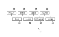
- FIG. 2A is a diagram illustrating an example of the configuration of the head mounted display (HMD) 12 according to the present embodiment.
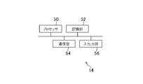
- FIG. 2B is a diagram illustrating an example of the configuration of the entertainment apparatus 14 according to the present embodiment.
- FIG. 2C is a diagram illustrating an example of the configuration of the relay device 16 according to the present embodiment.
- the entertainment system 10 includes an HMD 12, an entertainment device 14, a relay device 16, a display 18, a camera microphone unit 20, and a controller 22.
- the HMD 12 includes a processor 30, a storage unit 32, a communication unit 34, an input / output unit 36, a display unit 38, a sensor unit 40, an audio output unit 42, and a camera unit 44. included.
- the processor 30 is a program control device such as a microprocessor that operates according to a program installed in the HMD 12, for example.
- the HMD 12 may include a control circuit capable of implementing the processing executed by the processor 30 instead of the processor 30.
- the storage unit 32 is, for example, a storage element such as a ROM or a RAM.
- the storage unit 32 stores a program executed by the processor 30 and the like.
- the communication unit 34 is a communication interface such as a wireless LAN module. In the present embodiment, as illustrated in FIG. 1, the communication unit 34 is disposed on the upper front side of the HMD 12.
- the input / output unit 36 is an input / output port such as an HDMI (registered trademark) (High-Definition Multimedia Interface) port, a USB port, an AUX port, or the like.
- HDMI registered trademark
- AUX AUX port
- the display unit 38 is a display such as a liquid crystal display or an organic EL display disposed on the front side of the HMD 12 and displays a video generated by the entertainment device 14.
- the display unit 38 is housed in the housing of the HMD 12.
- the display unit 38 may receive a video signal output from the entertainment device 14 and relayed by the relay device 16 and output a video represented by the video signal.
- the display unit 38 according to the present embodiment can display a three-dimensional image by displaying a left-eye image and a right-eye image, for example.
- the display unit 38 may not be able to display a three-dimensional image and can only display a two-dimensional image.
- the sensor unit 40 is a sensor such as a motion sensor capable of detecting acceleration and angular velocity, for example.
- the sensor unit 40 outputs detection results such as the rotation amount and movement amount of the HMD 12 to the processor 30 at a predetermined sampling rate.
- the audio output unit 42 is a speaker arranged in the vicinity of the user's ear, such as a headphone or an earphone, for example, and outputs the audio represented by the audio data generated by the entertainment device 14.
- the audio output unit 42 receives an audio signal output from the entertainment device 14 and relayed by the relay device 16, for example, and outputs the audio represented by the audio signal.
- the camera unit 44 is a camera such as a digital camera, for example, and shoots a situation around the user wearing the HMD 12 at a predetermined frame rate. As shown in FIG. 1, two camera units 44 according to the present embodiment are arranged above the display unit 38 so that the front of the display unit 38 can be photographed. Therefore, the camera unit 44 according to the present embodiment can photograph the front of the user wearing the HMD 12.
- the camera unit 44 according to the present embodiment is a stereo camera including a lens for taking a left-eye image and a lens for generating a right-eye image, for example.
- the entertainment device 14 is a computer such as a game console, a DVD player, a Blu-ray (registered trademark) player, or the like.
- the entertainment device 14 according to the present embodiment generates video and audio by, for example, executing a stored game program or reproducing content recorded on an optical disc. Then, the entertainment device 14 according to the present embodiment outputs a video signal representing the generated video and an audio signal representing the generated audio to the HMD 12 and the display 18 via the relay device 16.
- the entertainment device 14 includes a processor 50, a storage unit 52, a communication unit 54, and an input / output unit 56, for example, as shown in FIG. 2B.
- the processor 50 is a program control device such as a CPU that operates in accordance with a program installed in the entertainment device 14, for example.
- the processor 50 according to the present embodiment also includes a GPU (Graphics Processing Unit) that draws an image in a frame buffer based on graphics commands and data supplied from the CPU.
- the entertainment device 14 may include a control circuit capable of implementing processing executed by the processor 50 instead of the processor 50.
- the storage unit 52 is, for example, a storage element such as a ROM or a RAM, a hard disk drive, or the like.
- the storage unit 52 stores a program executed by the processor 50 and the like.
- a frame buffer area in which an image is rendered by the GPU is secured.
- the communication unit 54 is a communication interface such as a wireless LAN module.
- the input / output unit 56 is an input / output port such as an HDMI port or a USB port.
- the relay device 16 is a computer that relays video signals and audio signals output from the entertainment device 14 and outputs them to the HMD 12 and the display 18.
- the relay device 16 includes a processor 60, a storage unit 62, a communication unit 64, and an input / output unit 66 as shown in FIG. 2C, for example.
- the processor 60 is a program control device such as a CPU that operates according to a program installed in the relay device 16, for example.
- the relay device 16 may include a control circuit capable of implementing the processing executed by the processor 60 instead of the processor 60.
- the storage unit 62 is a storage element such as a ROM or a RAM.
- the storage unit 62 stores a program executed by the processor 60 and the like.
- the communication unit 64 is a communication interface such as a wireless LAN module. In the present embodiment, as shown in FIG. 1, a communication unit 64 is included on the front side of the relay device 16.
- the input / output unit 66 is an input / output port such as an HDMI port or a USB port.
- the display 18 is, for example, a liquid crystal display, and displays a video or the like represented by a video signal output from the entertainment device 14.
- the camera microphone unit 20 includes a camera 20a that outputs data representing the state of the periphery of the camera microphone unit 20, such as an image obtained by capturing a subject, to the entertainment device 14.
- the camera 20a according to this embodiment is a stereo camera.
- the camera microphone unit 20 according to the present embodiment includes a microphone 20b that acquires ambient sound, converts the sound into sound data, and outputs the sound data to the entertainment device 14.
- the HMD 12 and the relay device 16 can mutually transmit and receive data by wireless communication, for example.
- the entertainment device 14 and the relay device 16 are connected via, for example, an HDMI cable or a USB cable.
- the relay device 16 and the display 18 are connected via, for example, an HDMI cable.
- the entertainment apparatus 14 and the camera microphone unit 20 are connected via, for example, an AUX cable.
- the controller 22 is an operation input device for performing operation input to the entertainment device 14.
- the user can perform various operation inputs using the controller 22 by pressing a direction key or button provided in the controller 22 or tilting an operation stick.
- the controller 22 outputs input data associated with the operation input to the entertainment device 14.
- the controller 22 according to the present embodiment includes a USB port. And the controller 22 can output input data to the entertainment apparatus 14 with a wire by connecting with the entertainment apparatus 14 with a USB cable.
- the controller 22 according to the present embodiment includes a wireless communication module and the like, and can output input data to the entertainment apparatus 14 wirelessly.
- the entertainment device 14 executes a program such as a game program. And the entertainment apparatus 14 produces
- the video data representing the video generated by the entertainment device 14 is transmitted from the entertainment device 14 to the HMD 12 via the relay device 16.
- sensing data is generated in the HMD 12.
- examples of the sensing data include data indicating the detection results of acceleration and angular velocity detected by the sensor unit 40, and images captured by the camera unit 44.
- the sensing data generated by the HMD 12 is transmitted to the entertainment device 14 via the relay device 16.
- the entertainment device 14 generates an image corresponding to the sensing data received from the HMD 12. For example, the entertainment device 14 changes the position and the line-of-sight direction of the viewpoint arranged in the virtual space according to the sensing data received from the HMD 12. Then, the entertainment device 14 generates an image representing a state in which the changed line-of-sight direction is viewed from the changed viewpoint position, and transmits the generated image to the HMD 12.
- the HMD 12 that has received the video causes the display unit 38 to display the video.
- the video displayed on the display unit 38 changes according to the movement of the user's head.
- FIG. 3 is a diagram schematically illustrating an example of half-duplex wireless communication between the relay device 16 and the HMD 12.
- transmission of video data from the relay device 16 to the HMD 12 and transmission of sensing data from the HMD 12 to the relay device 16 are performed alternately.
- a period during which data is transmitted from the relay device 16 to the HMD 12 is referred to as a first period
- a period during which data is transmitted from the HMD 12 to the relay device 16 is referred to as a second period. That is, in the half-duplex wireless communication according to the present embodiment, the first period and the second period come alternately.
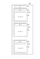
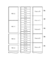
- FIG. 4 is a diagram showing an example of the data structure of the transaction data 70 according to this embodiment.
- the transaction data 70 transmitted from the relay apparatus 16 to the HMD 12 in one first period includes video data transmitted from the relay apparatus 16 to the HMD 12 in the first period.
- the transaction data 70 transmitted from the HMD 12 to the relay device 16 in one second period includes sensing data transmitted from the HMD 12 to the relay device 16 in the second period.
- one transaction data 70 includes one packet header 72 (expressed as PH in FIG. 4) and a plurality of divided packets 74.
- FIG. 4 shows that (N + 1) divided packets 74 are included in the transaction data 70.
- One fragmented packet 74 includes one piece of fragment information 76 (expressed as FI (0) in FIG. 4) and one payload data 78 (expressed as Payload (0) in FIG. 4). .
- the packet header 72 of the transaction data 70 transmitted from the relay device 16 to the HMD 12 includes, for example, a bit rate value (a value PayloadBitrate_HtoP described later) that can be transmitted from the HMD 12 to the relay device 16.
- a bit rate value (a value PayloadBitrate_HtoP described later) that can be transmitted from the HMD 12 to the relay device 16.
- the packet header 72 of the transaction data 70 transmitted by the HMD 12 to the relay device 16 includes, for example, a value (a value TransSize_PtoH_Act described later) indicating the size of data that the HMD 12 has successfully received.
- the packet header 72 includes, for example, the sequence number of the last divided packet 74.
- the fragment information 76 included in the fragment packet 74 includes, for example, the sequence number of the fragment packet 74 and the sequence number of the last fragment packet 74 in the transaction data 70 including the fragment packet 74.
- the payload data 78 corresponds to, for example, video data transmitted from the relay device 16 to the HMD 12 or sensing data transmitted from the HMD 12 to the relay device 16.
- FIG. 5 is a diagram illustrating an example of a relationship between video data transmitted from the relay device 16 to the HMD 12 and payload data 78 corresponding to the video data.
- the video data according to the present embodiment is encoded in accordance with, for example, the MPEG standard.
- the encoded video data is divided into packetized elementary streams (Packetized Elementary Stream) that are variable-length packets.
- FIG. 5 shows four PES packets (PES (0) to PES (3)).
- the PES is further divided into transport packets (TS) having a fixed length of 188 bytes including a header of 4 bytes and a payload of 184 bytes.
- TS transport packets
- FIG. 5 shows 20 TS (TS (0) to TS (19)).
- TS (0) to TS (5) six TSs (TS (0) to TS (5)) are generated based on PES (0).
- TS (6) to TS (11) are generated based on PES (1).
- TS (12) to TS (16) are generated based on PES (2).
- TS (17) to TS (19) are generated based on PES (3).
- a predetermined value is padded in the portion.
- payload data 78 corresponding to one or a plurality of TSs is generated.
- five pieces of payload data 78 (Payload (0) to Payload (4)) are shown.
- Payload (0) is shown to correspond to TS (0) to TS (3).
- Payload (1) is shown to correspond to TS (4) to TS (7).
- Payload (2) is shown to correspond to TS (8) to TS (11).
- Payload (3) is shown to correspond to TS (12) to TS (15).
- Payload (4) is shown to correspond to TS (16) to TS (19).
- the payload data 78 is always aligned with the TS, one TS is not divided into a plurality of payload data 78 and assigned.
- the relay device 16 transmits a packet header 72 to the HMD 12, and subsequently transmits the remaining transaction data 70 to the HMD 12.
- the HMD 12 transmits the packet header 72 to the relay device 16 in one second period subsequent to the first period, and then relays the remaining transaction data 70. Transmit to device 16.
- data other than the transaction data 70 such as voice data and control messages may be communicated between the relay device 16 and the HMD 12.
- the relay device 16 transmits a video data packet header 72 until receiving all sensing data transmitted in response to reception of the video data.
- the time (round trip time) required for round-trip communication can be specified.
- this time is expressed as time T_RT.
- the time T_RT corresponds to the time taken for one round-trip communication corresponding to the period from the start of transmission of video data in one first period to the end of reception of sensing data in a second period following the first period. To do.
- the relay device 16 transmits the video data packet header 72 and then transmits the sensing data packet header 72 transmitted from the HMD 12 in response to the end of reception of the video data.
- the time to receive can be specified. This time substantially corresponds to the time taken to transmit the video data from the relay device 16 to the HMD 12. Hereinafter, this time is expressed as time T_ph. Further, the time obtained by subtracting the time T_ph from the time T_RT substantially corresponds to the time required for transmitting the sensing data from the HMD 12 to the relay device 16. Hereinafter, this time is expressed as time T_hp.
- a predetermined target time for one round trip communication by half duplex wireless communication is set in advance.
- the target time will be expressed as time TargetTransferTime.
- data used in the HMD 12 such as video data according to the present embodiment is as high as possible. Therefore, it is desirable that the size of data generated per unit time by the entertainment device 14 is as large as possible.
- the round trip time is made closer to the time TargetTransferTime even if the size of the data generated per unit time is reduced. Is important. For example, it is important to shorten the latency of each frame image constituting the video displayed by the HMD 12.
- the size of data generated by the entertainment apparatus 14 per unit time is controlled as follows so that the time T_RT is as short as possible or less than the time TargetTransferTime.
- a part of the data may be missing and the missing part may not reach the communication partner.
- one or a plurality of divided packets 74 may not reach the communication partner.
- the communication partner considers the size of the data that was successfully communicated, the time required for one round-trip communication will approach the given target time unless the size of the data generated per unit time is controlled. There may not be.
- the size of data generated per unit time is controlled based on the size of data that the communication partner has successfully communicated as follows.
- sensing data is transmitted from the HMD 12 to the relay device 16 even if a part of the data transmitted from the relay device 16 to the HMD 12 is lost as follows.
- FIG. 6 is a diagram illustrating an example of a change in time T_RT specified for each round-trip communication.
- beam forming occurs intermittently and continuously in the communication path search process.
- the time T_RT greatly fluctuates in the time range indicated from approximately 2000 microseconds to 5500 microseconds.
- a large amount of data is required in the next round-trip communication. May not be able to communicate. Therefore, in such a situation, it is better not to increase the size of data generated per unit time so much even when the time T_RT is shorter than the target time.
- the magnitude of the change in the value corresponding to the size of the data generated per unit time is estimated as follows in the following manner. It was made to correspond to the result of.
- the target time is determined in the next one-way communication.
- data communication can be performed in a shorter time.
- the next one-way communication is immediately started, the generation of the video data is not in time, and there is a possibility that empty video data is transmitted from the relay device 16 to the HMD 12. Transmission of such empty data is a waste of power consumption.
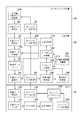
- FIG. 7 is a functional block diagram showing an example of functions implemented in the HMD 12, the entertainment device 14, and the relay device 16 according to the present embodiment. Note that in the entertainment system 10 according to the present embodiment, not all of the functions shown in FIG. 7 need be implemented, and functions other than the functions shown in FIG. 7 may be implemented.
- the entertainment apparatus 14 functionally includes, for example, a video data generation unit 80, a video data transmission unit 82, a generation control reception unit 84, and a sensing data reception unit 86.
- the video data generation unit 80 is mainly implemented by the processor 50.
- the video data transmission unit 82, the generation control reception unit 84, and the sensing data reception unit 86 are mainly mounted with the input / output unit 56.
- the above functions may be implemented by causing the processor 50 to execute a program that is installed in the entertainment device 14 that is a computer and that includes instructions corresponding to the above functions.
- This program may be supplied to the entertainment apparatus 14 via a computer-readable information storage medium such as an optical disk, a magnetic disk, a magnetic tape, a magneto-optical disk, or a flash memory, or via the Internet.
- the relay device 16 functionally includes, for example, a target time information storage unit 90, a video data reception unit 92, a video data buffer 94, a video data transmission unit 96, and sensing data.
- a receiving unit 98, a sensing data transmitting unit 100, a required time specifying unit 102, a search occurrence estimating unit 104, a bit rate determining unit 106, a data size determining unit 108, and a generation control unit 110 are included.
- the target time information storage unit 90 and the video data buffer 94 are mainly implemented by the storage unit 62.
- the video data receiving unit 92 and the sensing data transmitting unit 100 are mainly mounted with the input / output unit 66.
- the video data transmission unit 96 and the sensing data reception unit 98 are mainly implemented by the communication unit 64.
- the required time specifying unit 102, the search occurrence estimating unit 104, the bit rate determining unit 106, and the data size determining unit 108 are mainly implemented by the processor 60.
- the generation control unit 110 mainly includes the processor 60 and the input / output unit 66.
- the above functions may be implemented by causing the processor 60 to execute a program that is installed in the relay device 16 that is a computer and that includes instructions corresponding to the above functions.
- This program may be supplied to the relay device 16 via a computer-readable information storage medium such as an optical disk, a magnetic disk, a magnetic tape, a magneto-optical disk, or a flash memory, or via the Internet.
- the HMD 12 functionally includes, for example, a video data receiving unit 120, a video data output unit 122, a decoding unit 124, a display control unit 126, a sensing data generation unit 128, sensing A data buffer 130 and a sensing data transmission unit 132 are included.
- the video data receiving unit 120 and the sensing data transmitting unit 132 are mainly mounted with the communication unit 34.
- the video data output unit 122 and the decoding unit 124 are mainly implemented by the processor 30.
- the display control unit 126 is mainly implemented by the processor 30 and the display unit 38.
- the sensing data generation unit 128 mainly includes the processor 30, the sensor unit 40, and the camera unit 44.
- the sensing data buffer 130 is mainly implemented by the storage unit 32.
- the above functions may be implemented by causing the processor 30 to execute a program that is installed in the HMD 12 that is a computer and that includes instructions corresponding to the above functions.
- This program may be supplied to the HMD 12 via a computer-readable information storage medium such as an optical disk, a magnetic disk, a magnetic tape, a magneto-optical disk, or a flash memory, or via the Internet.
- the video data generation unit 80 generates video data representing a video displayed on the display unit 38 of the HMD 12, for example.
- the video data transmission unit 82 transmits the video data generated by the video data generation unit 80 to the relay device 16.
- the generation control receiving unit 84 receives generation control information transmitted by the relay device 16, for example.
- the generation control information is information indicating the size of data to be generated per unit time, for example.
- the video data generation unit 80 is controlled to generate data of the size indicated by the generation control information per unit time.
- the sensing data receiving unit 86 receives sensing data from the relay device 16 such as data indicating a detection result by the sensor unit 40 of the HMD 12 or an image taken by the camera unit 44, for example.
- the video data generating unit 80 generates video data corresponding to the sensing data received by the sensing data receiving unit 86.
- the target time information storage unit 90 stores target time information in which the value of the target time TargetTransferTime described above is set.
- the video data receiving unit 92 receives video data transmitted from the entertainment device 14, for example.
- the video data buffer 94 stores video data received by the video data receiving unit 92, for example.
- the video data transmission unit 96 transmits the video data generated by the video data generation unit 80 to the HMD 12.
- the video data transmission unit 96 transmits the video data stored in the video data buffer 94 to the HMD 12.
- the sensing data receiving unit 98 receives sensing data transmitted by the HMD 12, for example.
- the sensing data transmission unit 100 transmits the sensing data received by the sensing data reception unit 98 to the entertainment device 14, for example.
- the required time specifying unit 102 determines the time T_RT required for the one-way communication in response to the end of the one-way communication in the half-duplex wireless communication between the relay device 16 and the HMD 12. Is identified.
- the search occurrence estimation unit 104 estimates whether or not a communication route search process has occurred between the relay device 16 and the HMD 12.
- the communication path search process may include beamforming that occurs continuously.
- the search occurrence estimation unit 104 may determine an evaluation value as to whether or not a communication route search process has occurred based on the length of the time T_RT.
- the evaluation value a value obtained by subtracting a given value THR_INT described later from a value indicating the time T_RT can be cited.
- the bit rate determining unit 106 determines a bit rate that the relay device 16 can transmit to the HMD 12 in one round-trip communication.
- the bit rate is determined based on the specified time T_RT, the size of data communicated with the HMD 12 in one round-trip communication, and a given target time TargetTransferTime for one round-trip communication. May be.
- the bit rate determination unit 106 may determine a bit rate that the HMD 12 can transmit to the relay device 16.
- the bit rate value that can be transmitted to the HMD 12 by the relay device 16 is expressed as PayloadBitrate_PtoH.
- the bit rate value that the HMD 12 can transmit to the relay device 16 is expressed as PayloadBitrate_HtoP.
- the value PayloadBitrate_HtoP may be included in the packet header 72 of the transaction data 70 that the relay device 16 transmits to the HMD 12.
- the bit rate determination unit 106 may hold the determined value PayloadBitrate_PtoH.
- the bit rate determination unit 106 may hold the determined value PayloadBitrate_HtoP.
- the bit rate determination unit 106 may hold information indicating the maximum value and the minimum value of the bit rate that can be transmitted to the HMD 12 by the relay device 16 according to the specifications of the entertainment device 14 and the relay device 16, for example. Further, the bit rate determination unit 106 may hold information indicating the maximum value and the minimum value of the bit rate that can be transmitted to the relay device 16 by the HMD 12 according to the specifications of the HMD 12, for example.
- the maximum value and the minimum value of the bit rate that can be transmitted to the HMD 12 by the relay device 16 are expressed as Tp_PtoH_ReqMax and Tp_PtoH_ReqMin, respectively. Further, the maximum value and the minimum value of the bit rate that the HMD 12 can transmit to the relay apparatus 16 are expressed as Tp_HtoP_ReqMax and Tp_HtoP_ReqMin, respectively.
- the value Tp_PtoH_ReqMax for example, the communication band of the highest quality video data that satisfies the specifications of the HMD 12 and the relay device 16 and fixed data (for example, audio data, control messages, etc.) that is not the control target of the data amount is secured. It is desirable to set a value indicating a possible bit rate.
- the value Tp_HtoP_ReqMax is a bit rate that can secure the communication band of the highest quality sensing data that satisfies the specifications of the HMD 12 and the relay device 16 and fixed data that is not subject to control of the data amount (for example, voice data and control messages). It is desirable to set a value indicating.
- Tp_PtoH_ReqMin the communication bandwidth of the minimum quality video data that satisfies the specifications of the HMD 12 and the relay device 16 and fixed data (for example, audio data, control messages, etc.) that are not subject to control of the data amount. It is desirable to set a value indicating a bit rate that can be secured.
- Tp_HtoP_ReqMin the communication bandwidth of the minimum quality sensing data that satisfies the specifications of the HMD 12 and the relay device 16 and fixed data (for example, voice data, control messages, etc.) that are not subject to control of the data amount. It is desirable to set a value indicating a bit rate that can be secured.
- bit rate determination method The details of the bit rate determination method will be described later.
- the data size determination unit 108 determines the size of data that the relay device 16 transmits to the HMD 12 in one round-trip wireless communication performed with the HMD 12.
- the size of data to be transmitted by the relay device 16 to the HMD 12 in the next round-trip wireless communication is determined. Also good.
- the data size determination unit 108 may determine the size of data that the HMD 12 transmits to the relay device 16 in the subsequent one-way wireless communication.
- the size of data transmitted from the relay device 16 to the HMD 12 in one round-trip wireless communication is expressed as TransSize_PtoH.
- the size of data that the HMD 12 transmits to the relay device 16 in one round-trip wireless communication is expressed as TransSize_HtoP.
- the data size determination unit 108 may hold information in which the size value TransSize_PtoH of the data transmitted from the relay device 16 to the HMD 12 in one round-trip wireless communication is set as described above.
- the data size determination unit 108 may hold information in which the size value TransSize_HtoP of the data transmitted from the HMD 12 to the relay device 16 in one round-trip wireless communication is set as described above.
- the generation control unit 110 controls the size of data generated by the video data generation unit 80 per unit time.
- the size may be determined based on the time T_RT, the size of data communicated with the HMD 12 in one round-trip communication, and a given target time TargetTransferTime for one round-trip communication. Further, the size may be determined according to the bit rate determined by the bit rate determination unit 106.
- the generation control unit 110 may control the video data generation unit 80 so as to generate data having a size corresponding to the determined bit rate per unit time. Further, the generation control unit 110 may transmit generation control information indicating the size to the entertainment device 14.
- the generation control unit 110 may control quality such as resolution and compression rate of video data generated by the video data generation unit 80 according to the bit rate determined by the bit rate determination unit 106.
- the accuracy of the sensing data transmitted from the HMD 12 to the relay device 16 is reduced in one round-trip communication, the accuracy of the sensing data is deteriorated. Therefore, it is not desirable to reduce the size of the sensing data.
- the quality of the displayed video data is lowered, it does not matter so much. Therefore, when the bit rate at which the relay device 16 can transmit to the HMD 12 is lowered, if the quality such as the compression rate and resolution of the generated video is lowered to prevent the occurrence of latency, the accuracy of the sensing data is improved. It can be secured.
- the video data receiving unit 120 receives video data transmitted from the relay device 16.
- the video data output unit 122 outputs video data received by the video data receiving unit 120 to the decoding unit 124, for example.
- the video data output unit 122 When the video data output unit 122 fails to receive a part of the video data transmitted by the relay device 16, the video data output unit 122 decodes the video data supplemented with predetermined data such as NULL TS for the part. May be output.
- data loss occurs in units of divided packets 74.
- the video data output unit 122 outputs video data that complements the portions corresponding to TS (4) to TS (7) with predetermined data such as NULL TS to the decoding unit 124.
- the decoding unit 124 decodes video data received from the video data output unit 122, for example.
- PES is generated based on video data received from the video data output unit 122.
- the decoding unit 124 fails. In this case, no PES is generated. For example, as described above, it is assumed that portions corresponding to TS (4) and TS (5) are complemented with predetermined data such as NULL TS. In this case, the decoding unit 124 fails to generate PES (0) including TS (4) and TS (5) as a part. For example, it is assumed that portions corresponding to TS (6) and TS (7) are complemented with predetermined data such as NULL TS. In this case, the decoding unit 124 fails to generate PES (1) including TS (6) and TS (7) as a part.
- the display control unit 126 displays the video represented by the video data received by the video data receiving unit 120.
- the display control unit 126 may display the video represented by the video data decoded by the decoding unit 124.
- the same image (part of the frame image) as the previous frame may be displayed without updating a part of the screen associated with the PES for which the decoding unit 124 has failed to decode.
- the decoding unit 124 fails to decode PES (0) and PES (1)
- a part of the screen associated with PES (0) and PES (1) is not updated and is immediately updated.
- the same image as the frame may be displayed.
- the sensing data generation unit 128 generates sensing data such as data indicating a detection result by the sensor unit 40 of the HMD 12 or an image taken by the camera unit 44, for example.
- the sensing data generation unit 128 may hold target time information in which the value of the target time TargetTransferTime described above is set.
- the sensing data buffer 130 stores sensing data generated by the sensing data generation unit 128, for example.
- the sensing data transmission unit 132 transmits the sensing data stored in the sensing data buffer 130 to the relay device 16.
- the size of data generated per unit time may be controlled based on the size of data that the HMD 12 that is the communication partner of the relay device 16 has successfully communicated with.
- a value indicating the size of data successfully received by the HMD 12 in one round-trip communication is expressed as TransSize_PtoH_Act.
- a value indicating the size of data that the relay device 16 has successfully received in one round-trip communication is expressed as TransSize_HtoP_Act.
- the value TransSize_PtoH_Act may indicate the size of data that the HMD 12 has successfully received in one first period.
- the value TransSize_HtoP_Act may indicate the size of data that the relay device 16 has successfully received in one second period following the first period.
- the sensing data transmission unit 132 of the HMD 12 may specify the size of data that the HMD 12 has successfully received. Then, the sensing data transmission unit 132 of the HMD 12 may transmit size data indicating the specified size to the relay device 16. Then, the generation control unit 110 of the relay device 16 may control the size of data generated by the video data generation unit 80 per unit time based on the size indicated by the size data.
- the sensing data transmission unit 132 of the HMD 12 may transmit the transaction data 70 including the value TransSize_PtoH_Act in the packet header 72 to the relay device 16. Then, the generation control unit 110 of the relay device 16 may control the size of data generated by the video data generation unit 80 per unit time based on the value TransSize_PtoH_Act included in the packet header 72.
- the sensing data transmission unit 132 may transmit the transaction data 70 including the value TransSize_PtoH_Act in the packet header 72 to the relay device 16 even when the HMD 12 fails to receive a part of the data transmitted by the relay device 16.
- the HMD 12 has successfully received the segment packet 74 including the fragment information 76 in which the last sequence number is set in the transaction data 70 including a plurality of segment packets 74 each assigned a sequence number in one communication.
- the sensing data transmission unit 132 may transmit the transaction data 70 including the value TransSize_PtoH_Act in the packet header 72 to the relay device 16.
- bit rate determination unit 106 of the relay device 16 may determine a bit rate that the relay device 16 can transmit to the HMD 12 based on the time T_RT, the value TransSize_PtoH_Act, and the target time TargetTransferTime.
- the data size determination unit 108 of the relay device 16 may determine the size of data generated by the video data generation unit 80 per unit time based on the time T_RT, the value TransSize_PtoH_Act, and the target time TargetTransferTime.
- the magnitude of the change corresponding to the size of the data generated per unit time corresponds to the estimation result of whether or not the communication route search process is occurring. It may be a thing.
- the bit rate determination unit 106 determines a value corresponding to the size of data generated by the video data generation unit 80 per unit time, which is determined based on the time T_RT and the target time TargetTransferTime. However, you may change so that it may become according to the result of estimation whether the communication route search process has generate
- the value to be determined may be changed so that the magnitude of the value change corresponds to the sum of the evaluation values determined by the search occurrence estimation unit 104 in the most recent single round-trip communication. .
- the determined value may be changed so that the change is smaller than the case.
- the communication path search process is not generated but is generated.
- the determined value may be changed so as to be a larger change.
- the video data generation unit 80 when the time T_RT taken for one round-trip communication is shorter than a given lower limit time, the video data generation unit 80 until the lower limit time elapses from the start of the one round trip communication. You may control not to transmit the data which generate
- the generation control unit 110 may control the video data transmission unit 96 of the relay device 16 so as not to transmit the data generated by the video data generation unit 80.
- the above-mentioned lower limit time may be a time shorter than the target time TargetTransferTime.
- the video data described above may be transmitted from the entertainment device 14 to the relay device 16 and from the relay device 16 to the HMD 12 in the form of transaction data 70 shown in FIG.
- the transaction data 70 corresponding to the video data is generated in the video data generation unit 80.
- the generation control unit 110 controls the size of the transaction data 70 generated by the video data generation unit 80 per unit time.
- the sensing data described above may be transmitted from the HMD 12 to the relay device 16 and from the relay device 16 to the entertainment device 14 in the form of transaction data 70 shown in FIG.
- the transaction data 70 corresponding to the sensing data is generated in the sensing data generation unit 128.
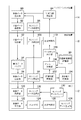
- the video data transmission unit 96 of the relay device 16 specifies the value TransSize_PtoH set in the information held by the data size determination unit 108 and the value PayloadBitrate_HtoP held by the bit rate determination unit 106 (S101). .
- the video data transmission unit 96 of the relay device 16 acquires the transaction data 70 having the size indicated by the value specified in the process shown in S101 from the video data buffer 94 and transmits it to the HMD 12. Then, the video data receiving unit 120 of the HMD 12 receives the transaction data 70 (S102).
- the transaction data 70 corresponds to video data.
- the video data transmission unit 96 sets the value PayloadBitrate_HtoP specified in the process shown in S101 in the packet header 72, and then transmits the transaction data 70 corresponding to the video data including the packet header 72.
- the video data output unit 122 of the HMD 12 outputs the transaction data 70 received in the process shown in S102 to the decoding unit 124 (S103).
- the video data output unit 122 outputs the transaction data 70 to the decoding unit 124 after supplementing the TS that failed to be received with predetermined data such as a NULL TS.
- the decoding unit 124 of the HMD 12 generates a PES by decoding the transaction data 70 received in the process shown in S103 (S104).
- a PES including a TS supplemented with predetermined data such as a NULL TS is not generated.
- the display control unit 126 of the HMD 12 displays an image corresponding to the PES generated in the process shown in S104 on the display unit 38 of the HMD 12 (S105).
- the displayed image is not updated for a part of the screen corresponding to the PES not generated here.
- the sensing data generation unit 128 of the HMD 12 generates transaction data 70 corresponding to the above-described sensing data, and stores the transaction data 70 in the sensing data buffer 130 (S106).
- transaction data 70 having a size corresponding to the value PayloadBitrate_HtoP set in the packet header 72 of the transaction data 70 received in the process shown in S102 is generated per unit time (for example, per second).
- the sensing data transmission part 132 of HMD12 transmits the transaction data 70 memorize
- the value TransSize_HtoP may be calculated. For example, a value obtained by multiplying the value PayloadBitrate_HtoP by the target time TargetTransferTime and dividing by 8 may be calculated as the value TransSize_HtoP. Then, transaction data 70 having a size corresponding to the calculated value TransSize_HtoP may be acquired from the sensing data buffer 130, and the acquired transaction data 70 may be transmitted.
- the unit of the value TransSize_HtoP is a byte
- the unit of the value PayloadBitrate_HtoP is a bit. Therefore, a process of dividing by 8 is performed to convert the bits into bytes.
- the sensing data transmission unit 132 sets a value TransSize_PtoH_Act indicating the size of the transaction data 70 successfully received by the HMD 12 in the packet header 72 and then includes transaction data corresponding to the sensing data. 70 is transmitted to the relay device 16.
- the sensing data receiving unit 98 of the relay device 16 fails to receive a part of the sensing data, the part may supplement predetermined data such as NULL TS.
- the required time specifying unit 102 of the relay device 16 specifies the time T_RT, the time T_ph, and the time T_hp (S108).
- the bit rate determination unit 106 of the relay device 16 specifies the value TransSize_PtoH_Act set in the packet header 72 of the transaction data 70 received in the process shown in S107 (S109).
- the bit rate determination unit 106 of the relay device 16 multiplies the value TransSize_PtoH_Act specified in the process shown in S109 by 8 and divides the value by the time T_ph specified in the process shown in S108, whereby the data transmission amount per unit time ( Throughput) value Tp_ph is calculated (S110).
- the unit of the value TransSize_PtoH_Act is a byte
- the unit of the value Tp_ph is a bit. For this reason, in the process shown in S110, a process of multiplying 8 to convert bytes into bits is executed.
- the bit rate determination unit 106 calculates a time new_time_ph that can be allocated to data transmission from the relay device 16 to the HMD 12 (S111).
- a value obtained by subtracting the time T_hp specified in the process shown in S108 from the target time information value TargetTransferTime stored in the target time information storage unit 90 and further subtracting a constant for absorbing jitter is calculated as the time new_time_ph.
- the constant may be, for example, a constant corresponding to 5 to 10% of the value TargetTransferTime.
- the bit rate determining unit 106 specifies a partial throughput value new_tp_ph corresponding to data transmission from the relay device 16 to the HMD 12 (S112).
- a value new_tp_ph is identified by multiplying the time new_time_ph calculated in the process shown in S111 by the value Tp_ph calculated in the process shown in S110 and dividing by the value TargetTransferTime.
- bit rate determination unit 106 determines the value PayloadBitrate_PtoH and the value PayloadBitrate_HtoP based on the value new_tp_ph specified in the process shown in S112 (S113).
- the value new_tp_ph is equal to or greater than a threshold value Tp_PtoH_LowThreshold used to determine a tendency to deteriorate the communication environment.
- Tp_PtoH_LowThreshold used to determine a tendency to deteriorate the communication environment.
- the value obtained as a result of performing the clipping process so as to be within the range from the value Tp_PtoH_ReqMin holding the specified value new_tp_ph to the value Tp_PtoH_ReqMax is determined as the value PayloadBitrate_PtoH.
- the value Tp_HtoP_ReqMax is determined as the value PayloadBitrate_HtoP.
- the threshold value Tp_PtoH_LowThreshold may be determined in a range not less than the value Tp_PtoH_ReqMin and not more than the value Tp_PtoH_ReqMax. More specifically, for example, the threshold value Tp_PtoH_LowThreshold may be a value obtained by dividing the sum of the value Tp_PtoH_ReqMin and the value Tp_PtoH_ReqMax by 2.
- the value new_tp_ph is smaller than the threshold value Tp_PtoH_LowThreshold.
- a value obtained by subtracting the value new_tp_ph from the threshold Tp_PtoH_LowThreshold is calculated as the value delta_tp_ph.
- a value obtained by subtracting the value delta_tp_ph from the value Tp_HtoP_ReqMax is calculated as a value new_tp_hp.
- the value new_tp_hp is changed to the value Tp_HtoP_ReqMin.
- a value obtained as a result of performing the clipping process so that the value new_tp_ph falls within the range from the held value Tp_PtoH_ReqMin to the value Tp_PtoH_ReqMax is determined as the value PayloadBitrate_PtoH. Also, the value new_tp_hp is determined as the value PayloadBitrate_HtoP.
- the HMD 12 transmits per unit time in the next round-trip communication. Data size will be reduced. In this case, the HMD 12 may output a message indicating that the communication environment has deteriorated.
- a part of the sensing data generated by the sensing data generating unit 128 and stored in the sensing data buffer 130 in the subsequent one-way communication is not transmitted by the sensing data transmitting unit 132 and is lost.
- the minimum quality video data is transmitted from the relay device 16 to the HMD 12.
- the sensing data generation unit 128 may reduce the size of data generated per unit time.
- the threshold value Tp_PtoH_LowThreshold may be a value corresponding to the distance between the relay device 16 and the HMD 12 or the direction of the HMD 12 with respect to the relay device 16.
- the bit rate determination unit 106 specifies the distance between the relay device 16 and the HMD 12 or the direction of the HMD 12 with respect to the relay device 16 based on the value of the sensing data received by the sensing data reception unit 86. May be. Then, the bit rate determination unit 106 may determine the threshold value Tp_PtoH_LowThreshold based on the specified distance or direction.
- a value obtained by dividing the sum of the value Tp_PtoH_ReqMax and the value Tp_PtoH_ReqMin by 2 may be the reference value of the threshold Tp_PtoH_LowThreshold.
- the threshold value Tp_PtoH_LowThreshold may be determined so that the value becomes larger than the reference value as the distance between the relay device 16 and the HMD 12 becomes longer. Further, for example, the threshold value is set so that the larger the angle between the direction from the user wearing the HMD 12 toward the relay device 16 and the direction from the back head to the front head of the user wearing the HMD 12 is, the larger the value is than the reference value.
- Tp_PtoH_LowThreshold may be determined.
- the bit rate determination unit 106 changes (corrects) the value PayloadBitrate_PtoH by executing a filtering process on the value PayloadBitrate_PtoH determined in the process shown in S113 (S114).
- the value determined based on the time T_RT and the target time TargetTransferTime may be corrected based on the estimation result of whether or not the communication route search process is occurring.
- a filtering process using a low-pass filter may be executed.
- the value PayloadBitrate_HtoP may be corrected by performing a filtering process on the value PayloadBitrate_HtoP.
- the value PayloadBitrate_PtoH and the value PayloadBitrate_HtoP held by the bit rate determining unit 106 are updated to the corrected values calculated in the process shown in S114.
- the data size determination unit 108 calculates the value TransSize_PtoH and the value TransSize_HtoP. Then, the data size determination unit 108 updates the value TransSize_PtoH and the value TransSize_PtoH held therein to the calculated values (S115).
- the value TransSize_PtoH may be calculated by multiplying the value PayloadBitrate_PtoH by the value TargetTransferTime indicated by the target time information stored in the target time information storage unit 90 and dividing the result by 8.
- the value PayloadBitrate_PtoH may be a value after being corrected in the process shown in S114.
- the value TransSize_HtoP may be calculated by multiplying the value PayloadBitrate_HtoP by the value TargetTransferTime indicated by the target time information stored in the target time information storage unit 90 and dividing the result by 8.
- the value PayloadBitrate_HtoP may be a value after being corrected by the process shown in S114.
- a process of dividing by 8 is performed to convert the bit into a byte.
- the generation control unit 110 transmits generation control information indicating the value PayloadBitrate_PtoH corrected in the process shown in S114 to the entertainment apparatus 14 (S116), and returns to the process shown in S101.
- the generation control reception unit 84 receives the generation control information, and the video data generation unit 80 generates transaction data 70 having a size corresponding to the value PayloadBitrate_PtoH per unit time (for example, per second).
- the video data transmission unit 96 transmits to the HMD 12 an instruction to reduce the size of data to be transmitted per unit time in the next round-trip communication.
- the bit rate of data transmitted from the HMD 12 to the relay device 16 can be controlled by the relay device 16.
- the filtering process shown in S114 described above may not be executed.
- the value TransSize_PtoH is calculated based on the value PayloadBitrate_PtoH determined in the process shown in S113.
- the value TransSize_HtoP is calculated based on the value PayloadBitrate_HtoP determined in the process shown in S113.
- the video data generation unit 80 may change the quality such as the resolution and compression rate of the generated video in accordance with the change in the value indicated by the generation control information transmitted in the process shown in S116. Good. For example, when the value indicated by the generation control information becomes small, the quality of the video generated by the video data generation unit 80 may be lowered.
- the value of the target time TargetTransferTime is assumed to be 1.5 milliseconds or 2 milliseconds, for example.
- the video data transmission unit 96 desirably transmits the transaction data 70 of 4 blocks (here, for example, 500 kilobytes) every 1.5 milliseconds.
- the sensing data transmission unit 132 desirably transmits 1 megabyte of transaction data 70 every 1.5 milliseconds.
- the video data transmission unit 96 may transmit the video data in units of a predetermined size block. For example, when the specified value TransSize_PtoH is 250 kilobytes, the video data transmission unit 96 may transmit video data of 2 blocks (here, for example, 250 kilobytes) in one round-trip communication. In this case, it is also possible to acquire two blocks in order from the latest block written in the video data buffer 94 and transmit these two blocks.
- the bit rate determination unit 106 may specify the value TransSize_HtoP_Act indicating the size of the transaction data 70 that the relay device 16 has successfully received. Then, the bit rate determination unit 106 may calculate the value Tp_hp of the data transmission amount (throughput) per unit time by multiplying the value TransSize_HtoP_Act by 8 and dividing by the time T_hp specified in the process shown in S108.
- the bit rate determination unit 106 may calculate a time new_time_hp that can be allocated to data transmission from the HMD 12 to the relay device 16.
- a value obtained by subtracting the time T_ph from the value TargetTransferTime of the target time information stored in the target time information storage unit 90 and further subtracting a constant for absorbing jitter may be calculated as the time new_time_hp.
- the bit rate determining unit 106 may specify a partial throughput value new_tp_hp corresponding to data transmission from the HMD 12 to the relay device 16.
- a value obtained by multiplying the calculated time new_time_hp by the value Tp_hp and dividing by the value TargetTransferTime may be specified as the value new_tp_hp.
- the value PayloadBitrate_HtoP may be calculated based on the value new_tp_hp.
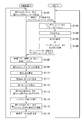
- the search occurrence estimation unit 104 also holds a given value THR_LOW, which is a reference for executing filtering processing in the Low mode, and a given value THR_HIGH, which is a reference for executing filtering processing in the High mode. I will do it.
- the bit rate determination unit 106 also holds an initial value DET_CNT of a variable Clear_Counter for determining to reset the variable Integrator to 0.
- the search occurrence estimating unit 104 compares the value indicating the time T_RT specified in the process shown in S108 with the value THR_INT (S201).
- the search occurrence estimating unit 104 adds a value obtained by subtracting the given value THR_INT from the value indicating the time T_RT to the value of the variable Integrator. (S202). Then, the search occurrence estimating unit 104 sets the value DET_CNT as the value of the variable Clear_Counter (S203).
- the search occurrence estimating unit 104 decreases the value of the variable Clear_Counter by 1 (S204).
- the search occurrence estimating unit 104 does not update the value of the variable Clear_Counter.
- the bit rate determining unit 106 checks whether or not the value of the variable Clear_Counter is 0 (S205).
- the process proceeds to S207. If it is confirmed that the value is 0 (S205: Y), the search occurrence estimating unit 104 sets the value of the variable Integrator to 0 (S206), and proceeds to the process shown in S207. That is, when the value indicating the time T_RT continuously for the number of times corresponding to the value DET_CNT is smaller than the value THR_INT, the value of the variable Integrator is reset to zero.
- the search occurrence estimating unit 104 confirms the value of the variable Integrator (S207).
- the process shown in S207 is also executed when it is confirmed in the process shown in S201 that the value indicating the time T_RT is the same as the value THR_INT.
- the bit rate determination unit 106 executes the filtering process in the high mode (S208), and the process illustrated in S114 ends.
- the bit rate determination unit 106 executes the filtering process in the Low mode (S209), and the process illustrated in S114 ends.
- the bit rate determining unit 106 executes the filtering process in the Normal mode (S210), and the process shown in S114 is ended.
- the value PayloadBitrate_PtoH is changed so that the difference from the value PayloadBitrate_PtoH held by the bit rate determination unit 106 is smaller in the High mode than in the Low mode, and in the Low mode than in the Normal mode.
- the filter constant may be determined so that the time constant in the high mode is larger than that in the low mode, and the time constant is larger in the low mode than in the normal mode.
- the value PayloadBitrate_PtoH may be changed so that
- the value PayloadBitrate_PtoH may be changed so that the difference between the stored value PayloadBitrate_PtoH is larger in the High mode and the Low mode than in the Normal mode.
- the filter constant may be determined so that the time constant is smaller in the high mode and the low mode than in the normal mode.
- the above-described coefficient in the high mode or the low mode may be larger than the above-described coefficient in the normal mode.
- the value PayloadBitrate_PtoH is changed in the High mode or the Low mode so that the change is larger than that in the Normal mode.
- the filtering process does not have to be executed in the High mode or the Low mode.
- the value PayloadBitrate_PtoH may be changed so that the difference from the held value PayloadBitrate_PtoH is larger in the High mode than in the Low mode.
- the value PayloadBitrate_PtoH may be changed so that the difference from the held value PayloadBitrate_PtoH is smaller in the High mode and the Low mode than in the Normal mode.
- the filter constant may be determined so that the time constant is larger in the High mode and the Low mode than in the Normal mode.
- the above-described coefficient in the high mode or the low mode may be smaller than the above-described coefficient in the normal mode. In this case, the value PayloadBitrate_PtoH is changed so that the change is smaller in the high mode and the low mode than in the normal mode.
- the value PayloadBitrate_PtoH may be changed so that the difference from the held value PayloadBitrate_PtoH is smaller in the High mode than in the Low mode.
- the filter constant may be determined based on the responsiveness of the video data generation unit 80.
- FIG. 10 is a functional block diagram showing an example of functions implemented by the HMD 12, the entertainment device 14, and the relay device 16 according to another embodiment of the present invention. Note that in the entertainment system 10 according to the present embodiment, not all of the functions shown in FIG. 10 need be implemented, and functions other than the functions shown in FIG. 10 may be implemented.
- the entertainment apparatus 14 functionally includes, for example, an uncompressed video data generation unit 140, a video data transmission unit 82, and a sensing data reception unit 86.
- the uncompressed video data generation unit 140 is mainly implemented by the processor 50.
- the video data transmitting unit 82 and the sensing data receiving unit 86 are mainly mounted with the input / output unit 56.
- the above functions may be implemented by causing the processor 50 to execute a program that is installed in the entertainment device 14 that is a computer and that includes instructions corresponding to the above functions.
- This program may be supplied to the entertainment apparatus 14 via a computer-readable information storage medium such as an optical disk, a magnetic disk, a magnetic tape, a magneto-optical disk, or a flash memory, or via the Internet.
- the relay device 16 functionally includes, for example, a target time information storage unit 90, a video data reception unit 92, a video data compression unit 150, a video data buffer 94, and video data.
- a transmission unit 96, a sensing data receiving unit 98, a sensing data transmitting unit 100, a required time specifying unit 102, a search occurrence estimating unit 104, a bit rate determining unit 106, a data size determining unit 108, and a generation control unit 110 are included.
- the target time information storage unit 90 and the video data buffer 94 are mainly implemented by the storage unit 62.
- the video data receiving unit 92 and the sensing data transmitting unit 100 are mainly mounted with the input / output unit 66.
- the video data transmission unit 96 and the sensing data reception unit 98 are mainly implemented by the communication unit 64.
- the required time specifying unit 102, the search occurrence estimating unit 104, the bit rate determining unit 106, the data size determining unit 108, and the video data compressing unit 150 are mainly implemented by the processor 60.
- the generation control unit 110 mainly includes the processor 60 and the input / output unit 66.
- the above functions may be implemented by causing the processor 60 to execute a program that is installed in the relay device 16 that is a computer and that includes instructions corresponding to the above functions.
- This program may be supplied to the relay device 16 via a computer-readable information storage medium such as an optical disk, a magnetic disk, a magnetic tape, a magneto-optical disk, or a flash memory, or via the Internet.
- the HMD 12 functionally includes, for example, a video data receiving unit 120, a video data output unit 122, a decoding unit 124, a display control unit 126, a sensing data generating unit 128, and a sensing.
- a data buffer 130 and a sensing data transmission unit 132 are included.
- the video data receiving unit 120 and the sensing data transmitting unit 132 are mainly mounted with the communication unit 34.
- the video data output unit 122 and the decoding unit 124 are mainly implemented by the processor 30.
- the display control unit 126 is mainly implemented by the processor 30 and the display unit 38.
- the sensing data generation unit 128 mainly includes the processor 30, the sensor unit 40, and the camera unit 44.
- the sensing data buffer 130 is mainly implemented by the storage unit 32.
- the above functions may be implemented by causing the processor 30 to execute a program that is installed in the HMD 12 that is a computer and that includes instructions corresponding to the above functions.
- This program may be supplied to the HMD 12 via a computer-readable information storage medium such as an optical disk, a magnetic disk, a magnetic tape, a magneto-optical disk, or a flash memory, or via the Internet.
- the uncompressed video data generation unit 140 generates uncompressed video data (uncompressed video data) representing the video displayed on the display unit 38 of the HMD 12.
- the video data transmission unit 82 transmits uncompressed video data generated by the uncompressed video data generation unit 140 to the relay device 16.
- the video data receiving unit 92 receives uncompressed video data transmitted from the entertainment device 14.
- the video data compression unit 150 generates compressed video data by compressing uncompressed video data received by the video data reception unit 92, for example.
- the video data compression unit 150 may generate the transaction data 70 corresponding to the compressed video data after compressing the uncompressed video data received by the video data reception unit 92.
- the video data buffer 94 stores the compressed video data generated by the video data compression unit 150, for example.
- the video data transmission unit 96 transmits the compressed video data generated by the video data compression unit 150 to the HMD 12.
- the video data transmission unit 96 transmits the video data stored in the video data buffer 94 to the HMD 12.
- the generation control unit 110 generates video data to generate data (for example, transaction data 70) having a size corresponding to the bit rate determined by the bit rate determination unit 106 as described above per unit time.
- the compression unit 150 is controlled.
- the generation control unit 110 may control the compression rate in the video compression by the video data compression unit 150 so as to generate data of a size corresponding to the determined bit rate per unit time.
- the generation control unit 110 controls the relay device 16 to generate data having a size corresponding to the determined bit rate per unit time. In this case, the generation control unit 110 does not transmit generation control information to the entertainment device 14.
Landscapes
- Engineering & Computer Science (AREA)
- Signal Processing (AREA)
- Multimedia (AREA)
- Computer Networks & Wireless Communication (AREA)
- Two-Way Televisions, Distribution Of Moving Picture Or The Like (AREA)
Abstract
La présente invention concerne un dispositif de communication, un procédé de commande de taille de données générées, un procédé de communication et un programme permettant de rapprocher le temps nécessaire à une communication aller-retour dans une communication sans fil en semi-duplex d'un temps cible donné. Selon la présente invention, une unité de transmission de données vidéo (96) transmet des données générées par une unité de génération de données vidéo (80) à un visiocasque (HMD) (12). Une unité de réception de données de détection (98) reçoit des données transmises par le HMD (12) comprenant des données de taille indiquant la taille des données que le HMD (12) a reçues avec succès. Une unité d'identification de temps requis (102) identifie le temps nécessaire à une communication aller-retour par communication sans fil en semi-duplex entre un dispositif relais (16) et le HMD (12). Une unité de commande de génération (110) commande la taille des données générées par unité de temps par l'unité de génération de données vidéo (80) sur la base du temps identifié, de la taille indiquée par les données de taille et d'un temps cible donné pour une communication aller-retour.
Priority Applications (3)
| Application Number | Priority Date | Filing Date | Title |
|---|---|---|---|
| JP2020512144A JP6938769B2 (ja) | 2018-04-04 | 2018-04-04 | 通信装置、生成データサイズ制御方法、通信方法及びプログラム |
| PCT/JP2018/014368 WO2019193667A1 (fr) | 2018-04-04 | 2018-04-04 | Dispositif de communication, procédé de commande de taille de données générées, procédé de communication et programme |
| US16/982,857 US11245890B2 (en) | 2018-04-04 | 2018-04-04 | Communication apparatus, generated data size control method, communication method, and program |
Applications Claiming Priority (1)
| Application Number | Priority Date | Filing Date | Title |
|---|---|---|---|
| PCT/JP2018/014368 WO2019193667A1 (fr) | 2018-04-04 | 2018-04-04 | Dispositif de communication, procédé de commande de taille de données générées, procédé de communication et programme |
Publications (1)
| Publication Number | Publication Date |
|---|---|
| WO2019193667A1 true WO2019193667A1 (fr) | 2019-10-10 |
Family
ID=68100518
Family Applications (1)
| Application Number | Title | Priority Date | Filing Date |
|---|---|---|---|
| PCT/JP2018/014368 WO2019193667A1 (fr) | 2018-04-04 | 2018-04-04 | Dispositif de communication, procédé de commande de taille de données générées, procédé de communication et programme |
Country Status (3)
| Country | Link |
|---|---|
| US (1) | US11245890B2 (fr) |
| JP (1) | JP6938769B2 (fr) |
| WO (1) | WO2019193667A1 (fr) |
Citations (3)
| Publication number | Priority date | Publication date | Assignee | Title |
|---|---|---|---|---|
| JP2008219479A (ja) * | 2007-03-05 | 2008-09-18 | Mitsubishi Electric Corp | 画像伝送システム、撮像装置、及び画像伝送方法 |
| JP2009027659A (ja) * | 2007-07-24 | 2009-02-05 | Hitachi Ltd | コンテンツ送信装置及びコンテンツ受信装置 |
| JP2011182262A (ja) * | 2010-03-02 | 2011-09-15 | Mitsubishi Electric Corp | 通信方法、コンテンツ送信装置及びコンテンツダウンロード装置 |
Family Cites Families (14)
| Publication number | Priority date | Publication date | Assignee | Title |
|---|---|---|---|---|
| JP3994388B2 (ja) * | 2003-03-18 | 2007-10-17 | ソニー株式会社 | 送受信システム、送信装置および方法、記録媒体、並びにプログラム |
| US8516069B1 (en) * | 2009-09-30 | 2013-08-20 | Viasat, Inc. | Optimizer-to-link layer interface using dynamic buffering |
| JP5931362B2 (ja) * | 2011-07-01 | 2016-06-08 | 日立マクセル株式会社 | コンテンツ送信装置及びコンテンツ送信方法 |
| WO2015097922A1 (fr) * | 2013-12-26 | 2015-07-02 | パナソニックIpマネジメント株式会社 | Disposition d'édition vidéo |
| EP3119027A4 (fr) * | 2014-03-10 | 2017-11-08 | Lg Electronics Inc. | Procédé pour déterminer la validité d'un signal dans un système de communication sans fil prenant en charge un changement d'utilisation de ressource radio, et appareil associé |
| CN111883032A (zh) * | 2014-10-15 | 2020-11-03 | 精工爱普生株式会社 | 显示设备、用于控制显示设备的方法和计算机可读介质 |
| JP6451238B2 (ja) * | 2014-11-17 | 2019-01-16 | セイコーエプソン株式会社 | 映像を送信または受信する装置、装置を制御する方法、コンピュータープログラム |
| JP6494439B2 (ja) * | 2015-06-05 | 2019-04-03 | キヤノン株式会社 | 通信装置およびその制御方法 |
| CN107231563B (zh) * | 2016-03-24 | 2020-06-23 | 腾讯科技(深圳)有限公司 | 视频处理方法和装置 |
| JP2019096920A (ja) * | 2016-04-07 | 2019-06-20 | シャープ株式会社 | 受信装置および送信装置 |
| US10931913B2 (en) | 2016-04-14 | 2021-02-23 | Sony Interactive Entertainment Inc. | Reception apparatus, transmission apparatus, control method, transmission method, and program |
| US10594361B2 (en) | 2016-06-15 | 2020-03-17 | Sony Interactive Entertainment Inc. | Communication system, communication apparatus, communication method, hopping pattern determining method and program |
| JP6231231B1 (ja) | 2017-01-25 | 2017-11-15 | パナソニック株式会社 | 映像送信装置、映像伝送システムおよび符号量制御方法 |
| WO2019193668A1 (fr) * | 2018-04-04 | 2019-10-10 | 株式会社ソニー・インタラクティブエンタテインメント | Dispositif de communication, procédé de commande de taille de données générées et programme |
-
2018
- 2018-04-04 WO PCT/JP2018/014368 patent/WO2019193667A1/fr active Application Filing
- 2018-04-04 JP JP2020512144A patent/JP6938769B2/ja active Active
- 2018-04-04 US US16/982,857 patent/US11245890B2/en active Active
Patent Citations (3)
| Publication number | Priority date | Publication date | Assignee | Title |
|---|---|---|---|---|
| JP2008219479A (ja) * | 2007-03-05 | 2008-09-18 | Mitsubishi Electric Corp | 画像伝送システム、撮像装置、及び画像伝送方法 |
| JP2009027659A (ja) * | 2007-07-24 | 2009-02-05 | Hitachi Ltd | コンテンツ送信装置及びコンテンツ受信装置 |
| JP2011182262A (ja) * | 2010-03-02 | 2011-09-15 | Mitsubishi Electric Corp | 通信方法、コンテンツ送信装置及びコンテンツダウンロード装置 |
Also Published As
| Publication number | Publication date |
|---|---|
| US11245890B2 (en) | 2022-02-08 |
| JPWO2019193667A1 (ja) | 2020-12-03 |
| US20210058601A1 (en) | 2021-02-25 |
| JP6938769B2 (ja) | 2021-09-22 |
Similar Documents
| Publication | Publication Date | Title |
|---|---|---|
| US9805691B2 (en) | Display, control method, and storage medium | |
| JP6585831B2 (ja) | 受信装置、送信装置、制御方法、送信方法及びプログラム | |
| JP6420500B2 (ja) | 周波数帯決定装置、ヘッドマウントディスプレイ、周波数帯決定方法及びプログラム | |
| US20180330163A1 (en) | Image processing apparatus and image processing method | |
| CN112533014B (zh) | 视频直播中目标物品信息处理和显示方法、装置及设备 | |
| WO2019193668A1 (fr) | Dispositif de communication, procédé de commande de taille de données générées et programme | |
| WO2020090477A1 (fr) | Système de réduction du mal des transports en rv, visiocasque, procédé de réduction du mal des transports en rv, et programme | |
| JP6616023B2 (ja) | 音声出力装置、ヘッドマウントディスプレイ、音声出力方法及びプログラム | |
| WO2019193667A1 (fr) | Dispositif de communication, procédé de commande de taille de données générées, procédé de communication et programme | |
| JP6679761B2 (ja) | 通信装置、生成データサイズ制御方法及びプログラム | |
| KR20210141295A (ko) | 엣지 컴퓨팅 서비스를 이용한 영상 컨텐츠 전송 방법 및 장치 | |
| US10594361B2 (en) | Communication system, communication apparatus, communication method, hopping pattern determining method and program | |
| US11146308B2 (en) | Transmitting device, receiving device, transmission method, reception method, and program | |
| EP4138395A1 (fr) | Procédé et appareil de transmission de contenu d'image utilisant un service informatique en périphérie | |
| US11563477B2 (en) | Information processing device and method | |
| TWI524767B (zh) | 接收裝置、螢幕畫面傳輸系統以及其傳輸方法 | |
| WO2018101162A1 (fr) | Visiocasque, dispositif de commande d'affichage, procédé de commande d'affichage et programme | |
| JP2006311519A (ja) | 通信システム、情報処理装置及びプログラム | |
| JP2009194759A (ja) | 映像ストリームの多重装置、分離装置、処理システム、方法、およびプログラム |
Legal Events
| Date | Code | Title | Description |
|---|---|---|---|
| 121 | Ep: the epo has been informed by wipo that ep was designated in this application |
Ref document number: 18913296 Country of ref document: EP Kind code of ref document: A1 |
|
| ENP | Entry into the national phase |
Ref document number: 2020512144 Country of ref document: JP Kind code of ref document: A |
|
| NENP | Non-entry into the national phase |
Ref country code: DE |
|
| 122 | Ep: pct application non-entry in european phase |
Ref document number: 18913296 Country of ref document: EP Kind code of ref document: A1 |