WO2019193667A1 - Communication device, generated data size control method, communication method, and program - Google Patents
Communication device, generated data size control method, communication method, and program Download PDFInfo
- Publication number
- WO2019193667A1 WO2019193667A1 PCT/JP2018/014368 JP2018014368W WO2019193667A1 WO 2019193667 A1 WO2019193667 A1 WO 2019193667A1 JP 2018014368 W JP2018014368 W JP 2018014368W WO 2019193667 A1 WO2019193667 A1 WO 2019193667A1
- Authority
- WO
- WIPO (PCT)
- Prior art keywords
- data
- communication
- unit
- size
- value
- Prior art date
Links
Images


Classifications
-
- H—ELECTRICITY
- H04—ELECTRIC COMMUNICATION TECHNIQUE
- H04N—PICTORIAL COMMUNICATION, e.g. TELEVISION
- H04N13/00—Stereoscopic video systems; Multi-view video systems; Details thereof
- H04N13/10—Processing, recording or transmission of stereoscopic or multi-view image signals
- H04N13/194—Transmission of image signals
-
- H—ELECTRICITY
- H04—ELECTRIC COMMUNICATION TECHNIQUE
- H04N—PICTORIAL COMMUNICATION, e.g. TELEVISION
- H04N13/00—Stereoscopic video systems; Multi-view video systems; Details thereof
- H04N13/10—Processing, recording or transmission of stereoscopic or multi-view image signals
- H04N13/106—Processing image signals
- H04N13/172—Processing image signals image signals comprising non-image signal components, e.g. headers or format information
-
- H—ELECTRICITY
- H04—ELECTRIC COMMUNICATION TECHNIQUE
- H04N—PICTORIAL COMMUNICATION, e.g. TELEVISION
- H04N21/00—Selective content distribution, e.g. interactive television or video on demand [VOD]
- H04N21/40—Client devices specifically adapted for the reception of or interaction with content, e.g. set-top-box [STB]; Operations thereof
- H04N21/43—Processing of content or additional data, e.g. demultiplexing additional data from a digital video stream; Elementary client operations, e.g. monitoring of home network or synchronising decoder's clock; Client middleware
- H04N21/436—Interfacing a local distribution network, e.g. communicating with another STB or one or more peripheral devices inside the home
-
- H—ELECTRICITY
- H04—ELECTRIC COMMUNICATION TECHNIQUE
- H04N—PICTORIAL COMMUNICATION, e.g. TELEVISION
- H04N21/00—Selective content distribution, e.g. interactive television or video on demand [VOD]
- H04N21/40—Client devices specifically adapted for the reception of or interaction with content, e.g. set-top-box [STB]; Operations thereof
- H04N21/43—Processing of content or additional data, e.g. demultiplexing additional data from a digital video stream; Elementary client operations, e.g. monitoring of home network or synchronising decoder's clock; Client middleware
- H04N21/44—Processing of video elementary streams, e.g. splicing a video clip retrieved from local storage with an incoming video stream, rendering scenes according to MPEG-4 scene graphs
- H04N21/4402—Processing of video elementary streams, e.g. splicing a video clip retrieved from local storage with an incoming video stream, rendering scenes according to MPEG-4 scene graphs involving reformatting operations of video signals for household redistribution, storage or real-time display
-
- H—ELECTRICITY
- H04—ELECTRIC COMMUNICATION TECHNIQUE
- H04W—WIRELESS COMMUNICATION NETWORKS
- H04W72/00—Local resource management
- H04W72/20—Control channels or signalling for resource management
- H04W72/23—Control channels or signalling for resource management in the downlink direction of a wireless link, i.e. towards a terminal
-
- H—ELECTRICITY
- H04—ELECTRIC COMMUNICATION TECHNIQUE
- H04L—TRANSMISSION OF DIGITAL INFORMATION, e.g. TELEGRAPHIC COMMUNICATION
- H04L5/00—Arrangements affording multiple use of the transmission path
- H04L5/14—Two-way operation using the same type of signal, i.e. duplex
- H04L5/16—Half-duplex systems; Simplex/duplex switching; Transmission of break signals non-automatically inverting the direction of transmission
-
- H—ELECTRICITY
- H04—ELECTRIC COMMUNICATION TECHNIQUE
- H04N—PICTORIAL COMMUNICATION, e.g. TELEVISION
- H04N13/00—Stereoscopic video systems; Multi-view video systems; Details thereof
- H04N13/20—Image signal generators
- H04N13/204—Image signal generators using stereoscopic image cameras
- H04N13/239—Image signal generators using stereoscopic image cameras using two 2D image sensors having a relative position equal to or related to the interocular distance
-
- H—ELECTRICITY
- H04—ELECTRIC COMMUNICATION TECHNIQUE
- H04N—PICTORIAL COMMUNICATION, e.g. TELEVISION
- H04N13/00—Stereoscopic video systems; Multi-view video systems; Details thereof
- H04N13/30—Image reproducers
- H04N13/332—Displays for viewing with the aid of special glasses or head-mounted displays [HMD]
- H04N13/344—Displays for viewing with the aid of special glasses or head-mounted displays [HMD] with head-mounted left-right displays
Definitions
- the present invention relates to a communication device, a generated data size control method, a communication method, and a program.
- HMDs head mounted displays
- an entertainment device that executes a program such as a game program, and that receive and display video generated by the entertainment device.
- some HMDs change the displayed video according to the movement of the user's head.
- Such an HMD includes, for example, a motion sensor and a camera, generates sensing data such as data indicating the detection result of the motion sensor and an image taken by the camera, and transmits the generated sensing data to the entertainment apparatus.
- the entertainment device that has received the sensing data generates a video based on the sensing data and transmits the video to the HMD.
- the HMD displays the received video, so that the user can appreciate the video that changes according to the movement of the head.
- the communication path between the entertainment device and the HMD includes a communication path by half-duplex wireless communication in accordance with a standard such as Wi-Fi (registered trademark), for example.
- a standard such as Wi-Fi (registered trademark)
- data is transmitted from a transmitting device (hereinafter referred to as a communication device) to a receiving device (hereinafter referred to as a communication partner device), and data is transmitted from the communication partner device to the communication device.
- a communication partner device a transmitting device
- a communication partner device receives from the communication partner device.
- transmission of video data from the entertainment device to the HMD and transmission of sensing data from the HMD to the entertainment device are alternately performed.
- the data used in the communication partner device such as the data constituting the video generated by the entertainment device
- the data used in the communication partner device is as high as possible.
- the displayed video has as high a picture quality as possible. Therefore, it is desirable that the size of data generated per unit time, such as data constituting video generated by an entertainment device, be as large as possible.
- the time required for one round-trip communication is given even if the size of data generated per unit time is reduced. It is important to approach the target time.
- the time required for one round-trip communication is given. It can be considered to approach the target time.
- the time required for one round-trip communication approaches the given target time unless the communication partner controls the size of the data generated per unit time in consideration of the size of data successfully communicated. There may not be.
- the present invention has been made in view of the above problems, and one of its purposes is a communication device capable of bringing the time required for one round-trip communication in half-duplex wireless communication closer to a given target time.
- the object is to provide a data size control method, a communication method, and a program.
- a communication apparatus is a communication apparatus that performs half-duplex wireless communication with a communication partner apparatus, and transmits data generated by a data generation unit to the communication partner apparatus.
- a transmission unit that receives data transmitted from the communication partner device, including size data indicating a size of the data that the communication partner device has successfully received, and the communication partner device.
- a time specifying unit for specifying the time taken for one round-trip communication by half-duplex wireless communication, the specified time, the size indicated by the size data, and a given target time for one round-trip communication
- a generation control unit that controls a size of data generated by the data generation unit per unit time.
- the time specifying unit receives data transmitted by the communication counterpart device in a second period following the first period from the start of transmission of data to the communication counterpart device in the first period.
- the time required for one round-trip communication corresponding to the end of is determined, and the receiving unit receives the size data indicating the size of data that the communication partner device has successfully received in the first period.
- the reception unit receives sensing data transmitted from the communication partner device, the data generation unit generates video data, and the generation control unit Control data quality.
- Another communication device is a communication device that performs half-duplex wireless communication with a communication partner device, a reception unit that receives data from the communication partner device, and data that has been successfully received.
- a transmission unit that transmits size data indicating a size of the communication partner device to the communication partner device, wherein the transmission unit transmits the size data even when reception of a part of the data transmitted by the communication partner device fails.
- the reception unit further includes an output unit that receives encoded video data from the communication counterpart device and outputs the video data to the decoding unit, and the output unit includes: The video data supplemented with predetermined data for a part of the video data that has failed to be received is output to the decoding unit.
- the receiving unit receives a plurality of packets each assigned a sequence number in one communication, and the transmitting unit has a sequence number last in the plurality of packets.
- the size data is transmitted even if reception of at least one of the plurality of packets fails in response to reception of the plurality of packets.
- the generated data size control method includes a step of transmitting data generated by a data generation unit to a communication partner device, and size data indicating a size of the data that the communication partner device has successfully received, Receiving data transmitted from the communication counterpart device, specifying a time taken for one round-trip communication by half-duplex wireless communication with the communication counterpart device, and the specified time, Controlling the size of the data generated by the data generation unit per unit time based on the size indicated by the size data and a given target time for one round-trip communication.
- the communication method includes a step of receiving data from a communication partner device, and a step of transmitting size data indicating a size of data successfully received to the communication partner device, wherein the step of transmitting includes Then, the size data is transmitted even when reception of a part of the data transmitted by the communication partner device fails.
- the program according to the present invention includes a procedure for transmitting data generated by a data generation unit to a communication partner device, and size data indicating a size of the data that the communication partner device has successfully received from the communication partner device.
- another program according to the present invention includes a procedure for receiving data from a communication partner device, a procedure for transmitting size data indicating the size of successfully received data to the communication partner device, The size data is transmitted even when reception of a part of the data transmitted by the communication partner device fails.
- FIG. 1 is a diagram showing an example of the overall configuration of an entertainment system 10 according to an embodiment of the present invention.
- FIG. 2A is a diagram illustrating an example of the configuration of the head mounted display (HMD) 12 according to the present embodiment.
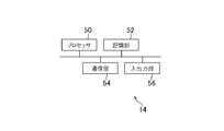
- FIG. 2B is a diagram illustrating an example of the configuration of the entertainment apparatus 14 according to the present embodiment.
- FIG. 2C is a diagram illustrating an example of the configuration of the relay device 16 according to the present embodiment.
- the entertainment system 10 includes an HMD 12, an entertainment device 14, a relay device 16, a display 18, a camera microphone unit 20, and a controller 22.
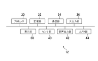
- the HMD 12 includes a processor 30, a storage unit 32, a communication unit 34, an input / output unit 36, a display unit 38, a sensor unit 40, an audio output unit 42, and a camera unit 44. included.
- the processor 30 is a program control device such as a microprocessor that operates according to a program installed in the HMD 12, for example.
- the HMD 12 may include a control circuit capable of implementing the processing executed by the processor 30 instead of the processor 30.
- the storage unit 32 is, for example, a storage element such as a ROM or a RAM.
- the storage unit 32 stores a program executed by the processor 30 and the like.
- the communication unit 34 is a communication interface such as a wireless LAN module. In the present embodiment, as illustrated in FIG. 1, the communication unit 34 is disposed on the upper front side of the HMD 12.
- the input / output unit 36 is an input / output port such as an HDMI (registered trademark) (High-Definition Multimedia Interface) port, a USB port, an AUX port, or the like.
- HDMI registered trademark
- AUX AUX port
- the display unit 38 is a display such as a liquid crystal display or an organic EL display disposed on the front side of the HMD 12 and displays a video generated by the entertainment device 14.
- the display unit 38 is housed in the housing of the HMD 12.
- the display unit 38 may receive a video signal output from the entertainment device 14 and relayed by the relay device 16 and output a video represented by the video signal.
- the display unit 38 according to the present embodiment can display a three-dimensional image by displaying a left-eye image and a right-eye image, for example.
- the display unit 38 may not be able to display a three-dimensional image and can only display a two-dimensional image.
- the sensor unit 40 is a sensor such as a motion sensor capable of detecting acceleration and angular velocity, for example.
- the sensor unit 40 outputs detection results such as the rotation amount and movement amount of the HMD 12 to the processor 30 at a predetermined sampling rate.
- the audio output unit 42 is a speaker arranged in the vicinity of the user's ear, such as a headphone or an earphone, for example, and outputs the audio represented by the audio data generated by the entertainment device 14.
- the audio output unit 42 receives an audio signal output from the entertainment device 14 and relayed by the relay device 16, for example, and outputs the audio represented by the audio signal.
- the camera unit 44 is a camera such as a digital camera, for example, and shoots a situation around the user wearing the HMD 12 at a predetermined frame rate. As shown in FIG. 1, two camera units 44 according to the present embodiment are arranged above the display unit 38 so that the front of the display unit 38 can be photographed. Therefore, the camera unit 44 according to the present embodiment can photograph the front of the user wearing the HMD 12.
- the camera unit 44 according to the present embodiment is a stereo camera including a lens for taking a left-eye image and a lens for generating a right-eye image, for example.
- the entertainment device 14 is a computer such as a game console, a DVD player, a Blu-ray (registered trademark) player, or the like.
- the entertainment device 14 according to the present embodiment generates video and audio by, for example, executing a stored game program or reproducing content recorded on an optical disc. Then, the entertainment device 14 according to the present embodiment outputs a video signal representing the generated video and an audio signal representing the generated audio to the HMD 12 and the display 18 via the relay device 16.
- the entertainment device 14 includes a processor 50, a storage unit 52, a communication unit 54, and an input / output unit 56, for example, as shown in FIG. 2B.
- the processor 50 is a program control device such as a CPU that operates in accordance with a program installed in the entertainment device 14, for example.
- the processor 50 according to the present embodiment also includes a GPU (Graphics Processing Unit) that draws an image in a frame buffer based on graphics commands and data supplied from the CPU.
- the entertainment device 14 may include a control circuit capable of implementing processing executed by the processor 50 instead of the processor 50.
- the storage unit 52 is, for example, a storage element such as a ROM or a RAM, a hard disk drive, or the like.
- the storage unit 52 stores a program executed by the processor 50 and the like.
- a frame buffer area in which an image is rendered by the GPU is secured.
- the communication unit 54 is a communication interface such as a wireless LAN module.
- the input / output unit 56 is an input / output port such as an HDMI port or a USB port.
- the relay device 16 is a computer that relays video signals and audio signals output from the entertainment device 14 and outputs them to the HMD 12 and the display 18.
- the relay device 16 includes a processor 60, a storage unit 62, a communication unit 64, and an input / output unit 66 as shown in FIG. 2C, for example.
- the processor 60 is a program control device such as a CPU that operates according to a program installed in the relay device 16, for example.
- the relay device 16 may include a control circuit capable of implementing the processing executed by the processor 60 instead of the processor 60.
- the storage unit 62 is a storage element such as a ROM or a RAM.
- the storage unit 62 stores a program executed by the processor 60 and the like.
- the communication unit 64 is a communication interface such as a wireless LAN module. In the present embodiment, as shown in FIG. 1, a communication unit 64 is included on the front side of the relay device 16.
- the input / output unit 66 is an input / output port such as an HDMI port or a USB port.
- the display 18 is, for example, a liquid crystal display, and displays a video or the like represented by a video signal output from the entertainment device 14.
- the camera microphone unit 20 includes a camera 20a that outputs data representing the state of the periphery of the camera microphone unit 20, such as an image obtained by capturing a subject, to the entertainment device 14.
- the camera 20a according to this embodiment is a stereo camera.
- the camera microphone unit 20 according to the present embodiment includes a microphone 20b that acquires ambient sound, converts the sound into sound data, and outputs the sound data to the entertainment device 14.
- the HMD 12 and the relay device 16 can mutually transmit and receive data by wireless communication, for example.
- the entertainment device 14 and the relay device 16 are connected via, for example, an HDMI cable or a USB cable.
- the relay device 16 and the display 18 are connected via, for example, an HDMI cable.
- the entertainment apparatus 14 and the camera microphone unit 20 are connected via, for example, an AUX cable.
- the controller 22 is an operation input device for performing operation input to the entertainment device 14.
- the user can perform various operation inputs using the controller 22 by pressing a direction key or button provided in the controller 22 or tilting an operation stick.
- the controller 22 outputs input data associated with the operation input to the entertainment device 14.
- the controller 22 according to the present embodiment includes a USB port. And the controller 22 can output input data to the entertainment apparatus 14 with a wire by connecting with the entertainment apparatus 14 with a USB cable.
- the controller 22 according to the present embodiment includes a wireless communication module and the like, and can output input data to the entertainment apparatus 14 wirelessly.
- the entertainment device 14 executes a program such as a game program. And the entertainment apparatus 14 produces
- the video data representing the video generated by the entertainment device 14 is transmitted from the entertainment device 14 to the HMD 12 via the relay device 16.
- sensing data is generated in the HMD 12.
- examples of the sensing data include data indicating the detection results of acceleration and angular velocity detected by the sensor unit 40, and images captured by the camera unit 44.
- the sensing data generated by the HMD 12 is transmitted to the entertainment device 14 via the relay device 16.
- the entertainment device 14 generates an image corresponding to the sensing data received from the HMD 12. For example, the entertainment device 14 changes the position and the line-of-sight direction of the viewpoint arranged in the virtual space according to the sensing data received from the HMD 12. Then, the entertainment device 14 generates an image representing a state in which the changed line-of-sight direction is viewed from the changed viewpoint position, and transmits the generated image to the HMD 12.
- the HMD 12 that has received the video causes the display unit 38 to display the video.
- the video displayed on the display unit 38 changes according to the movement of the user's head.
- FIG. 3 is a diagram schematically illustrating an example of half-duplex wireless communication between the relay device 16 and the HMD 12.
- transmission of video data from the relay device 16 to the HMD 12 and transmission of sensing data from the HMD 12 to the relay device 16 are performed alternately.
- a period during which data is transmitted from the relay device 16 to the HMD 12 is referred to as a first period
- a period during which data is transmitted from the HMD 12 to the relay device 16 is referred to as a second period. That is, in the half-duplex wireless communication according to the present embodiment, the first period and the second period come alternately.
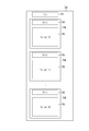
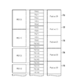
- FIG. 4 is a diagram showing an example of the data structure of the transaction data 70 according to this embodiment.
- the transaction data 70 transmitted from the relay apparatus 16 to the HMD 12 in one first period includes video data transmitted from the relay apparatus 16 to the HMD 12 in the first period.
- the transaction data 70 transmitted from the HMD 12 to the relay device 16 in one second period includes sensing data transmitted from the HMD 12 to the relay device 16 in the second period.
- one transaction data 70 includes one packet header 72 (expressed as PH in FIG. 4) and a plurality of divided packets 74.
- FIG. 4 shows that (N + 1) divided packets 74 are included in the transaction data 70.
- One fragmented packet 74 includes one piece of fragment information 76 (expressed as FI (0) in FIG. 4) and one payload data 78 (expressed as Payload (0) in FIG. 4). .
- the packet header 72 of the transaction data 70 transmitted from the relay device 16 to the HMD 12 includes, for example, a bit rate value (a value PayloadBitrate_HtoP described later) that can be transmitted from the HMD 12 to the relay device 16.
- a bit rate value (a value PayloadBitrate_HtoP described later) that can be transmitted from the HMD 12 to the relay device 16.
- the packet header 72 of the transaction data 70 transmitted by the HMD 12 to the relay device 16 includes, for example, a value (a value TransSize_PtoH_Act described later) indicating the size of data that the HMD 12 has successfully received.
- the packet header 72 includes, for example, the sequence number of the last divided packet 74.
- the fragment information 76 included in the fragment packet 74 includes, for example, the sequence number of the fragment packet 74 and the sequence number of the last fragment packet 74 in the transaction data 70 including the fragment packet 74.
- the payload data 78 corresponds to, for example, video data transmitted from the relay device 16 to the HMD 12 or sensing data transmitted from the HMD 12 to the relay device 16.
- FIG. 5 is a diagram illustrating an example of a relationship between video data transmitted from the relay device 16 to the HMD 12 and payload data 78 corresponding to the video data.
- the video data according to the present embodiment is encoded in accordance with, for example, the MPEG standard.
- the encoded video data is divided into packetized elementary streams (Packetized Elementary Stream) that are variable-length packets.
- FIG. 5 shows four PES packets (PES (0) to PES (3)).
- the PES is further divided into transport packets (TS) having a fixed length of 188 bytes including a header of 4 bytes and a payload of 184 bytes.
- TS transport packets
- FIG. 5 shows 20 TS (TS (0) to TS (19)).
- TS (0) to TS (5) six TSs (TS (0) to TS (5)) are generated based on PES (0).
- TS (6) to TS (11) are generated based on PES (1).
- TS (12) to TS (16) are generated based on PES (2).
- TS (17) to TS (19) are generated based on PES (3).
- a predetermined value is padded in the portion.
- payload data 78 corresponding to one or a plurality of TSs is generated.
- five pieces of payload data 78 (Payload (0) to Payload (4)) are shown.
- Payload (0) is shown to correspond to TS (0) to TS (3).
- Payload (1) is shown to correspond to TS (4) to TS (7).
- Payload (2) is shown to correspond to TS (8) to TS (11).
- Payload (3) is shown to correspond to TS (12) to TS (15).
- Payload (4) is shown to correspond to TS (16) to TS (19).
- the payload data 78 is always aligned with the TS, one TS is not divided into a plurality of payload data 78 and assigned.
- the relay device 16 transmits a packet header 72 to the HMD 12, and subsequently transmits the remaining transaction data 70 to the HMD 12.
- the HMD 12 transmits the packet header 72 to the relay device 16 in one second period subsequent to the first period, and then relays the remaining transaction data 70. Transmit to device 16.
- data other than the transaction data 70 such as voice data and control messages may be communicated between the relay device 16 and the HMD 12.
- the relay device 16 transmits a video data packet header 72 until receiving all sensing data transmitted in response to reception of the video data.
- the time (round trip time) required for round-trip communication can be specified.
- this time is expressed as time T_RT.
- the time T_RT corresponds to the time taken for one round-trip communication corresponding to the period from the start of transmission of video data in one first period to the end of reception of sensing data in a second period following the first period. To do.
- the relay device 16 transmits the video data packet header 72 and then transmits the sensing data packet header 72 transmitted from the HMD 12 in response to the end of reception of the video data.
- the time to receive can be specified. This time substantially corresponds to the time taken to transmit the video data from the relay device 16 to the HMD 12. Hereinafter, this time is expressed as time T_ph. Further, the time obtained by subtracting the time T_ph from the time T_RT substantially corresponds to the time required for transmitting the sensing data from the HMD 12 to the relay device 16. Hereinafter, this time is expressed as time T_hp.
- a predetermined target time for one round trip communication by half duplex wireless communication is set in advance.
- the target time will be expressed as time TargetTransferTime.
- data used in the HMD 12 such as video data according to the present embodiment is as high as possible. Therefore, it is desirable that the size of data generated per unit time by the entertainment device 14 is as large as possible.
- the round trip time is made closer to the time TargetTransferTime even if the size of the data generated per unit time is reduced. Is important. For example, it is important to shorten the latency of each frame image constituting the video displayed by the HMD 12.
- the size of data generated by the entertainment apparatus 14 per unit time is controlled as follows so that the time T_RT is as short as possible or less than the time TargetTransferTime.
- a part of the data may be missing and the missing part may not reach the communication partner.
- one or a plurality of divided packets 74 may not reach the communication partner.
- the communication partner considers the size of the data that was successfully communicated, the time required for one round-trip communication will approach the given target time unless the size of the data generated per unit time is controlled. There may not be.
- the size of data generated per unit time is controlled based on the size of data that the communication partner has successfully communicated as follows.
- sensing data is transmitted from the HMD 12 to the relay device 16 even if a part of the data transmitted from the relay device 16 to the HMD 12 is lost as follows.
- FIG. 6 is a diagram illustrating an example of a change in time T_RT specified for each round-trip communication.
- beam forming occurs intermittently and continuously in the communication path search process.
- the time T_RT greatly fluctuates in the time range indicated from approximately 2000 microseconds to 5500 microseconds.
- a large amount of data is required in the next round-trip communication. May not be able to communicate. Therefore, in such a situation, it is better not to increase the size of data generated per unit time so much even when the time T_RT is shorter than the target time.
- the magnitude of the change in the value corresponding to the size of the data generated per unit time is estimated as follows in the following manner. It was made to correspond to the result of.
- the target time is determined in the next one-way communication.
- data communication can be performed in a shorter time.
- the next one-way communication is immediately started, the generation of the video data is not in time, and there is a possibility that empty video data is transmitted from the relay device 16 to the HMD 12. Transmission of such empty data is a waste of power consumption.
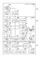
- FIG. 7 is a functional block diagram showing an example of functions implemented in the HMD 12, the entertainment device 14, and the relay device 16 according to the present embodiment. Note that in the entertainment system 10 according to the present embodiment, not all of the functions shown in FIG. 7 need be implemented, and functions other than the functions shown in FIG. 7 may be implemented.
- the entertainment apparatus 14 functionally includes, for example, a video data generation unit 80, a video data transmission unit 82, a generation control reception unit 84, and a sensing data reception unit 86.
- the video data generation unit 80 is mainly implemented by the processor 50.
- the video data transmission unit 82, the generation control reception unit 84, and the sensing data reception unit 86 are mainly mounted with the input / output unit 56.
- the above functions may be implemented by causing the processor 50 to execute a program that is installed in the entertainment device 14 that is a computer and that includes instructions corresponding to the above functions.
- This program may be supplied to the entertainment apparatus 14 via a computer-readable information storage medium such as an optical disk, a magnetic disk, a magnetic tape, a magneto-optical disk, or a flash memory, or via the Internet.
- the relay device 16 functionally includes, for example, a target time information storage unit 90, a video data reception unit 92, a video data buffer 94, a video data transmission unit 96, and sensing data.
- a receiving unit 98, a sensing data transmitting unit 100, a required time specifying unit 102, a search occurrence estimating unit 104, a bit rate determining unit 106, a data size determining unit 108, and a generation control unit 110 are included.
- the target time information storage unit 90 and the video data buffer 94 are mainly implemented by the storage unit 62.
- the video data receiving unit 92 and the sensing data transmitting unit 100 are mainly mounted with the input / output unit 66.
- the video data transmission unit 96 and the sensing data reception unit 98 are mainly implemented by the communication unit 64.
- the required time specifying unit 102, the search occurrence estimating unit 104, the bit rate determining unit 106, and the data size determining unit 108 are mainly implemented by the processor 60.
- the generation control unit 110 mainly includes the processor 60 and the input / output unit 66.
- the above functions may be implemented by causing the processor 60 to execute a program that is installed in the relay device 16 that is a computer and that includes instructions corresponding to the above functions.
- This program may be supplied to the relay device 16 via a computer-readable information storage medium such as an optical disk, a magnetic disk, a magnetic tape, a magneto-optical disk, or a flash memory, or via the Internet.
- the HMD 12 functionally includes, for example, a video data receiving unit 120, a video data output unit 122, a decoding unit 124, a display control unit 126, a sensing data generation unit 128, sensing A data buffer 130 and a sensing data transmission unit 132 are included.
- the video data receiving unit 120 and the sensing data transmitting unit 132 are mainly mounted with the communication unit 34.
- the video data output unit 122 and the decoding unit 124 are mainly implemented by the processor 30.
- the display control unit 126 is mainly implemented by the processor 30 and the display unit 38.
- the sensing data generation unit 128 mainly includes the processor 30, the sensor unit 40, and the camera unit 44.
- the sensing data buffer 130 is mainly implemented by the storage unit 32.
- the above functions may be implemented by causing the processor 30 to execute a program that is installed in the HMD 12 that is a computer and that includes instructions corresponding to the above functions.
- This program may be supplied to the HMD 12 via a computer-readable information storage medium such as an optical disk, a magnetic disk, a magnetic tape, a magneto-optical disk, or a flash memory, or via the Internet.
- the video data generation unit 80 generates video data representing a video displayed on the display unit 38 of the HMD 12, for example.
- the video data transmission unit 82 transmits the video data generated by the video data generation unit 80 to the relay device 16.
- the generation control receiving unit 84 receives generation control information transmitted by the relay device 16, for example.
- the generation control information is information indicating the size of data to be generated per unit time, for example.
- the video data generation unit 80 is controlled to generate data of the size indicated by the generation control information per unit time.
- the sensing data receiving unit 86 receives sensing data from the relay device 16 such as data indicating a detection result by the sensor unit 40 of the HMD 12 or an image taken by the camera unit 44, for example.
- the video data generating unit 80 generates video data corresponding to the sensing data received by the sensing data receiving unit 86.
- the target time information storage unit 90 stores target time information in which the value of the target time TargetTransferTime described above is set.
- the video data receiving unit 92 receives video data transmitted from the entertainment device 14, for example.
- the video data buffer 94 stores video data received by the video data receiving unit 92, for example.
- the video data transmission unit 96 transmits the video data generated by the video data generation unit 80 to the HMD 12.
- the video data transmission unit 96 transmits the video data stored in the video data buffer 94 to the HMD 12.
- the sensing data receiving unit 98 receives sensing data transmitted by the HMD 12, for example.
- the sensing data transmission unit 100 transmits the sensing data received by the sensing data reception unit 98 to the entertainment device 14, for example.
- the required time specifying unit 102 determines the time T_RT required for the one-way communication in response to the end of the one-way communication in the half-duplex wireless communication between the relay device 16 and the HMD 12. Is identified.
- the search occurrence estimation unit 104 estimates whether or not a communication route search process has occurred between the relay device 16 and the HMD 12.
- the communication path search process may include beamforming that occurs continuously.
- the search occurrence estimation unit 104 may determine an evaluation value as to whether or not a communication route search process has occurred based on the length of the time T_RT.
- the evaluation value a value obtained by subtracting a given value THR_INT described later from a value indicating the time T_RT can be cited.
- the bit rate determining unit 106 determines a bit rate that the relay device 16 can transmit to the HMD 12 in one round-trip communication.
- the bit rate is determined based on the specified time T_RT, the size of data communicated with the HMD 12 in one round-trip communication, and a given target time TargetTransferTime for one round-trip communication. May be.
- the bit rate determination unit 106 may determine a bit rate that the HMD 12 can transmit to the relay device 16.
- the bit rate value that can be transmitted to the HMD 12 by the relay device 16 is expressed as PayloadBitrate_PtoH.
- the bit rate value that the HMD 12 can transmit to the relay device 16 is expressed as PayloadBitrate_HtoP.
- the value PayloadBitrate_HtoP may be included in the packet header 72 of the transaction data 70 that the relay device 16 transmits to the HMD 12.
- the bit rate determination unit 106 may hold the determined value PayloadBitrate_PtoH.
- the bit rate determination unit 106 may hold the determined value PayloadBitrate_HtoP.
- the bit rate determination unit 106 may hold information indicating the maximum value and the minimum value of the bit rate that can be transmitted to the HMD 12 by the relay device 16 according to the specifications of the entertainment device 14 and the relay device 16, for example. Further, the bit rate determination unit 106 may hold information indicating the maximum value and the minimum value of the bit rate that can be transmitted to the relay device 16 by the HMD 12 according to the specifications of the HMD 12, for example.
- the maximum value and the minimum value of the bit rate that can be transmitted to the HMD 12 by the relay device 16 are expressed as Tp_PtoH_ReqMax and Tp_PtoH_ReqMin, respectively. Further, the maximum value and the minimum value of the bit rate that the HMD 12 can transmit to the relay apparatus 16 are expressed as Tp_HtoP_ReqMax and Tp_HtoP_ReqMin, respectively.
- the value Tp_PtoH_ReqMax for example, the communication band of the highest quality video data that satisfies the specifications of the HMD 12 and the relay device 16 and fixed data (for example, audio data, control messages, etc.) that is not the control target of the data amount is secured. It is desirable to set a value indicating a possible bit rate.
- the value Tp_HtoP_ReqMax is a bit rate that can secure the communication band of the highest quality sensing data that satisfies the specifications of the HMD 12 and the relay device 16 and fixed data that is not subject to control of the data amount (for example, voice data and control messages). It is desirable to set a value indicating.
- Tp_PtoH_ReqMin the communication bandwidth of the minimum quality video data that satisfies the specifications of the HMD 12 and the relay device 16 and fixed data (for example, audio data, control messages, etc.) that are not subject to control of the data amount. It is desirable to set a value indicating a bit rate that can be secured.
- Tp_HtoP_ReqMin the communication bandwidth of the minimum quality sensing data that satisfies the specifications of the HMD 12 and the relay device 16 and fixed data (for example, voice data, control messages, etc.) that are not subject to control of the data amount. It is desirable to set a value indicating a bit rate that can be secured.
- bit rate determination method The details of the bit rate determination method will be described later.
- the data size determination unit 108 determines the size of data that the relay device 16 transmits to the HMD 12 in one round-trip wireless communication performed with the HMD 12.
- the size of data to be transmitted by the relay device 16 to the HMD 12 in the next round-trip wireless communication is determined. Also good.
- the data size determination unit 108 may determine the size of data that the HMD 12 transmits to the relay device 16 in the subsequent one-way wireless communication.
- the size of data transmitted from the relay device 16 to the HMD 12 in one round-trip wireless communication is expressed as TransSize_PtoH.
- the size of data that the HMD 12 transmits to the relay device 16 in one round-trip wireless communication is expressed as TransSize_HtoP.
- the data size determination unit 108 may hold information in which the size value TransSize_PtoH of the data transmitted from the relay device 16 to the HMD 12 in one round-trip wireless communication is set as described above.
- the data size determination unit 108 may hold information in which the size value TransSize_HtoP of the data transmitted from the HMD 12 to the relay device 16 in one round-trip wireless communication is set as described above.
- the generation control unit 110 controls the size of data generated by the video data generation unit 80 per unit time.
- the size may be determined based on the time T_RT, the size of data communicated with the HMD 12 in one round-trip communication, and a given target time TargetTransferTime for one round-trip communication. Further, the size may be determined according to the bit rate determined by the bit rate determination unit 106.
- the generation control unit 110 may control the video data generation unit 80 so as to generate data having a size corresponding to the determined bit rate per unit time. Further, the generation control unit 110 may transmit generation control information indicating the size to the entertainment device 14.
- the generation control unit 110 may control quality such as resolution and compression rate of video data generated by the video data generation unit 80 according to the bit rate determined by the bit rate determination unit 106.
- the accuracy of the sensing data transmitted from the HMD 12 to the relay device 16 is reduced in one round-trip communication, the accuracy of the sensing data is deteriorated. Therefore, it is not desirable to reduce the size of the sensing data.
- the quality of the displayed video data is lowered, it does not matter so much. Therefore, when the bit rate at which the relay device 16 can transmit to the HMD 12 is lowered, if the quality such as the compression rate and resolution of the generated video is lowered to prevent the occurrence of latency, the accuracy of the sensing data is improved. It can be secured.
- the video data receiving unit 120 receives video data transmitted from the relay device 16.
- the video data output unit 122 outputs video data received by the video data receiving unit 120 to the decoding unit 124, for example.
- the video data output unit 122 When the video data output unit 122 fails to receive a part of the video data transmitted by the relay device 16, the video data output unit 122 decodes the video data supplemented with predetermined data such as NULL TS for the part. May be output.
- data loss occurs in units of divided packets 74.
- the video data output unit 122 outputs video data that complements the portions corresponding to TS (4) to TS (7) with predetermined data such as NULL TS to the decoding unit 124.
- the decoding unit 124 decodes video data received from the video data output unit 122, for example.
- PES is generated based on video data received from the video data output unit 122.
- the decoding unit 124 fails. In this case, no PES is generated. For example, as described above, it is assumed that portions corresponding to TS (4) and TS (5) are complemented with predetermined data such as NULL TS. In this case, the decoding unit 124 fails to generate PES (0) including TS (4) and TS (5) as a part. For example, it is assumed that portions corresponding to TS (6) and TS (7) are complemented with predetermined data such as NULL TS. In this case, the decoding unit 124 fails to generate PES (1) including TS (6) and TS (7) as a part.
- the display control unit 126 displays the video represented by the video data received by the video data receiving unit 120.
- the display control unit 126 may display the video represented by the video data decoded by the decoding unit 124.
- the same image (part of the frame image) as the previous frame may be displayed without updating a part of the screen associated with the PES for which the decoding unit 124 has failed to decode.
- the decoding unit 124 fails to decode PES (0) and PES (1)
- a part of the screen associated with PES (0) and PES (1) is not updated and is immediately updated.
- the same image as the frame may be displayed.
- the sensing data generation unit 128 generates sensing data such as data indicating a detection result by the sensor unit 40 of the HMD 12 or an image taken by the camera unit 44, for example.
- the sensing data generation unit 128 may hold target time information in which the value of the target time TargetTransferTime described above is set.
- the sensing data buffer 130 stores sensing data generated by the sensing data generation unit 128, for example.
- the sensing data transmission unit 132 transmits the sensing data stored in the sensing data buffer 130 to the relay device 16.
- the size of data generated per unit time may be controlled based on the size of data that the HMD 12 that is the communication partner of the relay device 16 has successfully communicated with.
- a value indicating the size of data successfully received by the HMD 12 in one round-trip communication is expressed as TransSize_PtoH_Act.
- a value indicating the size of data that the relay device 16 has successfully received in one round-trip communication is expressed as TransSize_HtoP_Act.
- the value TransSize_PtoH_Act may indicate the size of data that the HMD 12 has successfully received in one first period.
- the value TransSize_HtoP_Act may indicate the size of data that the relay device 16 has successfully received in one second period following the first period.
- the sensing data transmission unit 132 of the HMD 12 may specify the size of data that the HMD 12 has successfully received. Then, the sensing data transmission unit 132 of the HMD 12 may transmit size data indicating the specified size to the relay device 16. Then, the generation control unit 110 of the relay device 16 may control the size of data generated by the video data generation unit 80 per unit time based on the size indicated by the size data.
- the sensing data transmission unit 132 of the HMD 12 may transmit the transaction data 70 including the value TransSize_PtoH_Act in the packet header 72 to the relay device 16. Then, the generation control unit 110 of the relay device 16 may control the size of data generated by the video data generation unit 80 per unit time based on the value TransSize_PtoH_Act included in the packet header 72.
- the sensing data transmission unit 132 may transmit the transaction data 70 including the value TransSize_PtoH_Act in the packet header 72 to the relay device 16 even when the HMD 12 fails to receive a part of the data transmitted by the relay device 16.
- the HMD 12 has successfully received the segment packet 74 including the fragment information 76 in which the last sequence number is set in the transaction data 70 including a plurality of segment packets 74 each assigned a sequence number in one communication.
- the sensing data transmission unit 132 may transmit the transaction data 70 including the value TransSize_PtoH_Act in the packet header 72 to the relay device 16.
- bit rate determination unit 106 of the relay device 16 may determine a bit rate that the relay device 16 can transmit to the HMD 12 based on the time T_RT, the value TransSize_PtoH_Act, and the target time TargetTransferTime.
- the data size determination unit 108 of the relay device 16 may determine the size of data generated by the video data generation unit 80 per unit time based on the time T_RT, the value TransSize_PtoH_Act, and the target time TargetTransferTime.
- the magnitude of the change corresponding to the size of the data generated per unit time corresponds to the estimation result of whether or not the communication route search process is occurring. It may be a thing.
- the bit rate determination unit 106 determines a value corresponding to the size of data generated by the video data generation unit 80 per unit time, which is determined based on the time T_RT and the target time TargetTransferTime. However, you may change so that it may become according to the result of estimation whether the communication route search process has generate
- the value to be determined may be changed so that the magnitude of the value change corresponds to the sum of the evaluation values determined by the search occurrence estimation unit 104 in the most recent single round-trip communication. .
- the determined value may be changed so that the change is smaller than the case.
- the communication path search process is not generated but is generated.
- the determined value may be changed so as to be a larger change.
- the video data generation unit 80 when the time T_RT taken for one round-trip communication is shorter than a given lower limit time, the video data generation unit 80 until the lower limit time elapses from the start of the one round trip communication. You may control not to transmit the data which generate
- the generation control unit 110 may control the video data transmission unit 96 of the relay device 16 so as not to transmit the data generated by the video data generation unit 80.
- the above-mentioned lower limit time may be a time shorter than the target time TargetTransferTime.
- the video data described above may be transmitted from the entertainment device 14 to the relay device 16 and from the relay device 16 to the HMD 12 in the form of transaction data 70 shown in FIG.
- the transaction data 70 corresponding to the video data is generated in the video data generation unit 80.
- the generation control unit 110 controls the size of the transaction data 70 generated by the video data generation unit 80 per unit time.
- the sensing data described above may be transmitted from the HMD 12 to the relay device 16 and from the relay device 16 to the entertainment device 14 in the form of transaction data 70 shown in FIG.
- the transaction data 70 corresponding to the sensing data is generated in the sensing data generation unit 128.
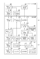
- the video data transmission unit 96 of the relay device 16 specifies the value TransSize_PtoH set in the information held by the data size determination unit 108 and the value PayloadBitrate_HtoP held by the bit rate determination unit 106 (S101). .
- the video data transmission unit 96 of the relay device 16 acquires the transaction data 70 having the size indicated by the value specified in the process shown in S101 from the video data buffer 94 and transmits it to the HMD 12. Then, the video data receiving unit 120 of the HMD 12 receives the transaction data 70 (S102).
- the transaction data 70 corresponds to video data.
- the video data transmission unit 96 sets the value PayloadBitrate_HtoP specified in the process shown in S101 in the packet header 72, and then transmits the transaction data 70 corresponding to the video data including the packet header 72.
- the video data output unit 122 of the HMD 12 outputs the transaction data 70 received in the process shown in S102 to the decoding unit 124 (S103).
- the video data output unit 122 outputs the transaction data 70 to the decoding unit 124 after supplementing the TS that failed to be received with predetermined data such as a NULL TS.
- the decoding unit 124 of the HMD 12 generates a PES by decoding the transaction data 70 received in the process shown in S103 (S104).
- a PES including a TS supplemented with predetermined data such as a NULL TS is not generated.
- the display control unit 126 of the HMD 12 displays an image corresponding to the PES generated in the process shown in S104 on the display unit 38 of the HMD 12 (S105).
- the displayed image is not updated for a part of the screen corresponding to the PES not generated here.
- the sensing data generation unit 128 of the HMD 12 generates transaction data 70 corresponding to the above-described sensing data, and stores the transaction data 70 in the sensing data buffer 130 (S106).
- transaction data 70 having a size corresponding to the value PayloadBitrate_HtoP set in the packet header 72 of the transaction data 70 received in the process shown in S102 is generated per unit time (for example, per second).
- the sensing data transmission part 132 of HMD12 transmits the transaction data 70 memorize
- the value TransSize_HtoP may be calculated. For example, a value obtained by multiplying the value PayloadBitrate_HtoP by the target time TargetTransferTime and dividing by 8 may be calculated as the value TransSize_HtoP. Then, transaction data 70 having a size corresponding to the calculated value TransSize_HtoP may be acquired from the sensing data buffer 130, and the acquired transaction data 70 may be transmitted.
- the unit of the value TransSize_HtoP is a byte
- the unit of the value PayloadBitrate_HtoP is a bit. Therefore, a process of dividing by 8 is performed to convert the bits into bytes.
- the sensing data transmission unit 132 sets a value TransSize_PtoH_Act indicating the size of the transaction data 70 successfully received by the HMD 12 in the packet header 72 and then includes transaction data corresponding to the sensing data. 70 is transmitted to the relay device 16.
- the sensing data receiving unit 98 of the relay device 16 fails to receive a part of the sensing data, the part may supplement predetermined data such as NULL TS.
- the required time specifying unit 102 of the relay device 16 specifies the time T_RT, the time T_ph, and the time T_hp (S108).
- the bit rate determination unit 106 of the relay device 16 specifies the value TransSize_PtoH_Act set in the packet header 72 of the transaction data 70 received in the process shown in S107 (S109).
- the bit rate determination unit 106 of the relay device 16 multiplies the value TransSize_PtoH_Act specified in the process shown in S109 by 8 and divides the value by the time T_ph specified in the process shown in S108, whereby the data transmission amount per unit time ( Throughput) value Tp_ph is calculated (S110).
- the unit of the value TransSize_PtoH_Act is a byte
- the unit of the value Tp_ph is a bit. For this reason, in the process shown in S110, a process of multiplying 8 to convert bytes into bits is executed.
- the bit rate determination unit 106 calculates a time new_time_ph that can be allocated to data transmission from the relay device 16 to the HMD 12 (S111).
- a value obtained by subtracting the time T_hp specified in the process shown in S108 from the target time information value TargetTransferTime stored in the target time information storage unit 90 and further subtracting a constant for absorbing jitter is calculated as the time new_time_ph.
- the constant may be, for example, a constant corresponding to 5 to 10% of the value TargetTransferTime.
- the bit rate determining unit 106 specifies a partial throughput value new_tp_ph corresponding to data transmission from the relay device 16 to the HMD 12 (S112).
- a value new_tp_ph is identified by multiplying the time new_time_ph calculated in the process shown in S111 by the value Tp_ph calculated in the process shown in S110 and dividing by the value TargetTransferTime.
- bit rate determination unit 106 determines the value PayloadBitrate_PtoH and the value PayloadBitrate_HtoP based on the value new_tp_ph specified in the process shown in S112 (S113).
- the value new_tp_ph is equal to or greater than a threshold value Tp_PtoH_LowThreshold used to determine a tendency to deteriorate the communication environment.
- Tp_PtoH_LowThreshold used to determine a tendency to deteriorate the communication environment.
- the value obtained as a result of performing the clipping process so as to be within the range from the value Tp_PtoH_ReqMin holding the specified value new_tp_ph to the value Tp_PtoH_ReqMax is determined as the value PayloadBitrate_PtoH.
- the value Tp_HtoP_ReqMax is determined as the value PayloadBitrate_HtoP.
- the threshold value Tp_PtoH_LowThreshold may be determined in a range not less than the value Tp_PtoH_ReqMin and not more than the value Tp_PtoH_ReqMax. More specifically, for example, the threshold value Tp_PtoH_LowThreshold may be a value obtained by dividing the sum of the value Tp_PtoH_ReqMin and the value Tp_PtoH_ReqMax by 2.
- the value new_tp_ph is smaller than the threshold value Tp_PtoH_LowThreshold.
- a value obtained by subtracting the value new_tp_ph from the threshold Tp_PtoH_LowThreshold is calculated as the value delta_tp_ph.
- a value obtained by subtracting the value delta_tp_ph from the value Tp_HtoP_ReqMax is calculated as a value new_tp_hp.
- the value new_tp_hp is changed to the value Tp_HtoP_ReqMin.
- a value obtained as a result of performing the clipping process so that the value new_tp_ph falls within the range from the held value Tp_PtoH_ReqMin to the value Tp_PtoH_ReqMax is determined as the value PayloadBitrate_PtoH. Also, the value new_tp_hp is determined as the value PayloadBitrate_HtoP.
- the HMD 12 transmits per unit time in the next round-trip communication. Data size will be reduced. In this case, the HMD 12 may output a message indicating that the communication environment has deteriorated.
- a part of the sensing data generated by the sensing data generating unit 128 and stored in the sensing data buffer 130 in the subsequent one-way communication is not transmitted by the sensing data transmitting unit 132 and is lost.
- the minimum quality video data is transmitted from the relay device 16 to the HMD 12.
- the sensing data generation unit 128 may reduce the size of data generated per unit time.
- the threshold value Tp_PtoH_LowThreshold may be a value corresponding to the distance between the relay device 16 and the HMD 12 or the direction of the HMD 12 with respect to the relay device 16.
- the bit rate determination unit 106 specifies the distance between the relay device 16 and the HMD 12 or the direction of the HMD 12 with respect to the relay device 16 based on the value of the sensing data received by the sensing data reception unit 86. May be. Then, the bit rate determination unit 106 may determine the threshold value Tp_PtoH_LowThreshold based on the specified distance or direction.
- a value obtained by dividing the sum of the value Tp_PtoH_ReqMax and the value Tp_PtoH_ReqMin by 2 may be the reference value of the threshold Tp_PtoH_LowThreshold.
- the threshold value Tp_PtoH_LowThreshold may be determined so that the value becomes larger than the reference value as the distance between the relay device 16 and the HMD 12 becomes longer. Further, for example, the threshold value is set so that the larger the angle between the direction from the user wearing the HMD 12 toward the relay device 16 and the direction from the back head to the front head of the user wearing the HMD 12 is, the larger the value is than the reference value.
- Tp_PtoH_LowThreshold may be determined.
- the bit rate determination unit 106 changes (corrects) the value PayloadBitrate_PtoH by executing a filtering process on the value PayloadBitrate_PtoH determined in the process shown in S113 (S114).
- the value determined based on the time T_RT and the target time TargetTransferTime may be corrected based on the estimation result of whether or not the communication route search process is occurring.
- a filtering process using a low-pass filter may be executed.
- the value PayloadBitrate_HtoP may be corrected by performing a filtering process on the value PayloadBitrate_HtoP.
- the value PayloadBitrate_PtoH and the value PayloadBitrate_HtoP held by the bit rate determining unit 106 are updated to the corrected values calculated in the process shown in S114.
- the data size determination unit 108 calculates the value TransSize_PtoH and the value TransSize_HtoP. Then, the data size determination unit 108 updates the value TransSize_PtoH and the value TransSize_PtoH held therein to the calculated values (S115).
- the value TransSize_PtoH may be calculated by multiplying the value PayloadBitrate_PtoH by the value TargetTransferTime indicated by the target time information stored in the target time information storage unit 90 and dividing the result by 8.
- the value PayloadBitrate_PtoH may be a value after being corrected in the process shown in S114.
- the value TransSize_HtoP may be calculated by multiplying the value PayloadBitrate_HtoP by the value TargetTransferTime indicated by the target time information stored in the target time information storage unit 90 and dividing the result by 8.
- the value PayloadBitrate_HtoP may be a value after being corrected by the process shown in S114.
- a process of dividing by 8 is performed to convert the bit into a byte.
- the generation control unit 110 transmits generation control information indicating the value PayloadBitrate_PtoH corrected in the process shown in S114 to the entertainment apparatus 14 (S116), and returns to the process shown in S101.
- the generation control reception unit 84 receives the generation control information, and the video data generation unit 80 generates transaction data 70 having a size corresponding to the value PayloadBitrate_PtoH per unit time (for example, per second).
- the video data transmission unit 96 transmits to the HMD 12 an instruction to reduce the size of data to be transmitted per unit time in the next round-trip communication.
- the bit rate of data transmitted from the HMD 12 to the relay device 16 can be controlled by the relay device 16.
- the filtering process shown in S114 described above may not be executed.
- the value TransSize_PtoH is calculated based on the value PayloadBitrate_PtoH determined in the process shown in S113.
- the value TransSize_HtoP is calculated based on the value PayloadBitrate_HtoP determined in the process shown in S113.
- the video data generation unit 80 may change the quality such as the resolution and compression rate of the generated video in accordance with the change in the value indicated by the generation control information transmitted in the process shown in S116. Good. For example, when the value indicated by the generation control information becomes small, the quality of the video generated by the video data generation unit 80 may be lowered.
- the value of the target time TargetTransferTime is assumed to be 1.5 milliseconds or 2 milliseconds, for example.
- the video data transmission unit 96 desirably transmits the transaction data 70 of 4 blocks (here, for example, 500 kilobytes) every 1.5 milliseconds.
- the sensing data transmission unit 132 desirably transmits 1 megabyte of transaction data 70 every 1.5 milliseconds.
- the video data transmission unit 96 may transmit the video data in units of a predetermined size block. For example, when the specified value TransSize_PtoH is 250 kilobytes, the video data transmission unit 96 may transmit video data of 2 blocks (here, for example, 250 kilobytes) in one round-trip communication. In this case, it is also possible to acquire two blocks in order from the latest block written in the video data buffer 94 and transmit these two blocks.
- the bit rate determination unit 106 may specify the value TransSize_HtoP_Act indicating the size of the transaction data 70 that the relay device 16 has successfully received. Then, the bit rate determination unit 106 may calculate the value Tp_hp of the data transmission amount (throughput) per unit time by multiplying the value TransSize_HtoP_Act by 8 and dividing by the time T_hp specified in the process shown in S108.
- the bit rate determination unit 106 may calculate a time new_time_hp that can be allocated to data transmission from the HMD 12 to the relay device 16.
- a value obtained by subtracting the time T_ph from the value TargetTransferTime of the target time information stored in the target time information storage unit 90 and further subtracting a constant for absorbing jitter may be calculated as the time new_time_hp.
- the bit rate determining unit 106 may specify a partial throughput value new_tp_hp corresponding to data transmission from the HMD 12 to the relay device 16.
- a value obtained by multiplying the calculated time new_time_hp by the value Tp_hp and dividing by the value TargetTransferTime may be specified as the value new_tp_hp.
- the value PayloadBitrate_HtoP may be calculated based on the value new_tp_hp.
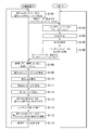
- the search occurrence estimation unit 104 also holds a given value THR_LOW, which is a reference for executing filtering processing in the Low mode, and a given value THR_HIGH, which is a reference for executing filtering processing in the High mode. I will do it.
- the bit rate determination unit 106 also holds an initial value DET_CNT of a variable Clear_Counter for determining to reset the variable Integrator to 0.
- the search occurrence estimating unit 104 compares the value indicating the time T_RT specified in the process shown in S108 with the value THR_INT (S201).
- the search occurrence estimating unit 104 adds a value obtained by subtracting the given value THR_INT from the value indicating the time T_RT to the value of the variable Integrator. (S202). Then, the search occurrence estimating unit 104 sets the value DET_CNT as the value of the variable Clear_Counter (S203).
- the search occurrence estimating unit 104 decreases the value of the variable Clear_Counter by 1 (S204).
- the search occurrence estimating unit 104 does not update the value of the variable Clear_Counter.
- the bit rate determining unit 106 checks whether or not the value of the variable Clear_Counter is 0 (S205).
- the process proceeds to S207. If it is confirmed that the value is 0 (S205: Y), the search occurrence estimating unit 104 sets the value of the variable Integrator to 0 (S206), and proceeds to the process shown in S207. That is, when the value indicating the time T_RT continuously for the number of times corresponding to the value DET_CNT is smaller than the value THR_INT, the value of the variable Integrator is reset to zero.
- the search occurrence estimating unit 104 confirms the value of the variable Integrator (S207).
- the process shown in S207 is also executed when it is confirmed in the process shown in S201 that the value indicating the time T_RT is the same as the value THR_INT.
- the bit rate determination unit 106 executes the filtering process in the high mode (S208), and the process illustrated in S114 ends.
- the bit rate determination unit 106 executes the filtering process in the Low mode (S209), and the process illustrated in S114 ends.
- the bit rate determining unit 106 executes the filtering process in the Normal mode (S210), and the process shown in S114 is ended.
- the value PayloadBitrate_PtoH is changed so that the difference from the value PayloadBitrate_PtoH held by the bit rate determination unit 106 is smaller in the High mode than in the Low mode, and in the Low mode than in the Normal mode.
- the filter constant may be determined so that the time constant in the high mode is larger than that in the low mode, and the time constant is larger in the low mode than in the normal mode.
- the value PayloadBitrate_PtoH may be changed so that
- the value PayloadBitrate_PtoH may be changed so that the difference between the stored value PayloadBitrate_PtoH is larger in the High mode and the Low mode than in the Normal mode.
- the filter constant may be determined so that the time constant is smaller in the high mode and the low mode than in the normal mode.
- the above-described coefficient in the high mode or the low mode may be larger than the above-described coefficient in the normal mode.
- the value PayloadBitrate_PtoH is changed in the High mode or the Low mode so that the change is larger than that in the Normal mode.
- the filtering process does not have to be executed in the High mode or the Low mode.
- the value PayloadBitrate_PtoH may be changed so that the difference from the held value PayloadBitrate_PtoH is larger in the High mode than in the Low mode.
- the value PayloadBitrate_PtoH may be changed so that the difference from the held value PayloadBitrate_PtoH is smaller in the High mode and the Low mode than in the Normal mode.
- the filter constant may be determined so that the time constant is larger in the High mode and the Low mode than in the Normal mode.
- the above-described coefficient in the high mode or the low mode may be smaller than the above-described coefficient in the normal mode. In this case, the value PayloadBitrate_PtoH is changed so that the change is smaller in the high mode and the low mode than in the normal mode.
- the value PayloadBitrate_PtoH may be changed so that the difference from the held value PayloadBitrate_PtoH is smaller in the High mode than in the Low mode.
- the filter constant may be determined based on the responsiveness of the video data generation unit 80.
- FIG. 10 is a functional block diagram showing an example of functions implemented by the HMD 12, the entertainment device 14, and the relay device 16 according to another embodiment of the present invention. Note that in the entertainment system 10 according to the present embodiment, not all of the functions shown in FIG. 10 need be implemented, and functions other than the functions shown in FIG. 10 may be implemented.
- the entertainment apparatus 14 functionally includes, for example, an uncompressed video data generation unit 140, a video data transmission unit 82, and a sensing data reception unit 86.
- the uncompressed video data generation unit 140 is mainly implemented by the processor 50.
- the video data transmitting unit 82 and the sensing data receiving unit 86 are mainly mounted with the input / output unit 56.
- the above functions may be implemented by causing the processor 50 to execute a program that is installed in the entertainment device 14 that is a computer and that includes instructions corresponding to the above functions.
- This program may be supplied to the entertainment apparatus 14 via a computer-readable information storage medium such as an optical disk, a magnetic disk, a magnetic tape, a magneto-optical disk, or a flash memory, or via the Internet.
- the relay device 16 functionally includes, for example, a target time information storage unit 90, a video data reception unit 92, a video data compression unit 150, a video data buffer 94, and video data.
- a transmission unit 96, a sensing data receiving unit 98, a sensing data transmitting unit 100, a required time specifying unit 102, a search occurrence estimating unit 104, a bit rate determining unit 106, a data size determining unit 108, and a generation control unit 110 are included.
- the target time information storage unit 90 and the video data buffer 94 are mainly implemented by the storage unit 62.
- the video data receiving unit 92 and the sensing data transmitting unit 100 are mainly mounted with the input / output unit 66.
- the video data transmission unit 96 and the sensing data reception unit 98 are mainly implemented by the communication unit 64.
- the required time specifying unit 102, the search occurrence estimating unit 104, the bit rate determining unit 106, the data size determining unit 108, and the video data compressing unit 150 are mainly implemented by the processor 60.
- the generation control unit 110 mainly includes the processor 60 and the input / output unit 66.
- the above functions may be implemented by causing the processor 60 to execute a program that is installed in the relay device 16 that is a computer and that includes instructions corresponding to the above functions.
- This program may be supplied to the relay device 16 via a computer-readable information storage medium such as an optical disk, a magnetic disk, a magnetic tape, a magneto-optical disk, or a flash memory, or via the Internet.
- the HMD 12 functionally includes, for example, a video data receiving unit 120, a video data output unit 122, a decoding unit 124, a display control unit 126, a sensing data generating unit 128, and a sensing.
- a data buffer 130 and a sensing data transmission unit 132 are included.
- the video data receiving unit 120 and the sensing data transmitting unit 132 are mainly mounted with the communication unit 34.
- the video data output unit 122 and the decoding unit 124 are mainly implemented by the processor 30.
- the display control unit 126 is mainly implemented by the processor 30 and the display unit 38.
- the sensing data generation unit 128 mainly includes the processor 30, the sensor unit 40, and the camera unit 44.
- the sensing data buffer 130 is mainly implemented by the storage unit 32.
- the above functions may be implemented by causing the processor 30 to execute a program that is installed in the HMD 12 that is a computer and that includes instructions corresponding to the above functions.
- This program may be supplied to the HMD 12 via a computer-readable information storage medium such as an optical disk, a magnetic disk, a magnetic tape, a magneto-optical disk, or a flash memory, or via the Internet.
- the uncompressed video data generation unit 140 generates uncompressed video data (uncompressed video data) representing the video displayed on the display unit 38 of the HMD 12.
- the video data transmission unit 82 transmits uncompressed video data generated by the uncompressed video data generation unit 140 to the relay device 16.
- the video data receiving unit 92 receives uncompressed video data transmitted from the entertainment device 14.
- the video data compression unit 150 generates compressed video data by compressing uncompressed video data received by the video data reception unit 92, for example.
- the video data compression unit 150 may generate the transaction data 70 corresponding to the compressed video data after compressing the uncompressed video data received by the video data reception unit 92.
- the video data buffer 94 stores the compressed video data generated by the video data compression unit 150, for example.
- the video data transmission unit 96 transmits the compressed video data generated by the video data compression unit 150 to the HMD 12.
- the video data transmission unit 96 transmits the video data stored in the video data buffer 94 to the HMD 12.
- the generation control unit 110 generates video data to generate data (for example, transaction data 70) having a size corresponding to the bit rate determined by the bit rate determination unit 106 as described above per unit time.
- the compression unit 150 is controlled.
- the generation control unit 110 may control the compression rate in the video compression by the video data compression unit 150 so as to generate data of a size corresponding to the determined bit rate per unit time.
- the generation control unit 110 controls the relay device 16 to generate data having a size corresponding to the determined bit rate per unit time. In this case, the generation control unit 110 does not transmit generation control information to the entertainment device 14.
Abstract
Provided are a communication device, generated data size control method, communication method, and program with which it is possible to make the time taken for one round-trip communication in half duplex wireless communication approach a given target time. In the present invention, a video data transmitting unit (96) transmits data generated by a video data generating unit (80) to an HMD (12). A sensing data receiving unit (98) receives data transmitted from the HMD (12) that includes size data indicating the size of data that the HMD (12) has successfully received. A required time identifying unit (102) identifies the time taken for one round-trip communication in half duplex wireless communication between a relay device (16) and the HMD (12). A generation control unit (110) controls the size of data generated per unit time by the video data generating unit (80) on the basis of the identified time, the size indicated by the size data, and a given target time for one round-trip communication.
Description
本発明は、通信装置、生成データサイズ制御方法、通信方法及びプログラムに関する。
The present invention relates to a communication device, a generated data size control method, a communication method, and a program.
近年、頭部に装着して眼前に表示される映像を鑑賞できるヘッドマウントディスプレイ(HMD)が普及し始めている。このようなHMDのなかには、ゲームプログラム等のプログラムを実行するエンタテインメント装置と有線接続されており、エンタテインメント装置で生成される映像を受信して表示させるものが存在する。
In recent years, head mounted displays (HMDs) that can be worn on the head and can be viewed in front of the eyes are becoming popular. Among such HMDs, there are devices that are wired to an entertainment device that executes a program such as a game program, and that receive and display video generated by the entertainment device.
またこのようなHMDのなかにはユーザの頭部の動きに応じて表示される映像が変化するものがある。このようなHMDは例えばモーションセンサやカメラなどを備えており、モーションセンサの検出結果を示すデータやカメラが撮影する画像などといったセンシングデータを生成し、生成されたセンシングデータをエンタテインメント装置に送信する。センシングデータを受信したエンタテインメント装置は、当該センシングデータに基づいて映像を生成して、当該映像をHMDに送信する。そしてHMDは受信した映像を表示させることで、ユーザは頭部の動きに応じて変化する映像を鑑賞できることとなる。
Also, some HMDs change the displayed video according to the movement of the user's head. Such an HMD includes, for example, a motion sensor and a camera, generates sensing data such as data indicating the detection result of the motion sensor and an image taken by the camera, and transmits the generated sensing data to the entertainment apparatus. The entertainment device that has received the sensing data generates a video based on the sensing data and transmits the video to the HMD. The HMD displays the received video, so that the user can appreciate the video that changes according to the movement of the head.
発明者らは、エンタテインメント装置とHMDとの間の通信経路に、例えばWi-Fi(登録商標)等の規格に沿った半二重無線通信による通信経路が含まれるようにすることを検討している。半二重無線通信では送信側の装置(以下、通信装置と呼ぶ。)から受信側の装置(以下、通信相手装置と呼ぶ。)へのデータの送信と、通信相手装置から通信装置へのデータの送信と、が交互に行われる。上述の例では、エンタテインメント装置からHMDへの映像のデータの送信と、HMDからエンタテインメント装置へのセンシングデータの送信と、が交互に行われる。
The inventors have considered that the communication path between the entertainment device and the HMD includes a communication path by half-duplex wireless communication in accordance with a standard such as Wi-Fi (registered trademark), for example. Yes. In half-duplex wireless communication, data is transmitted from a transmitting device (hereinafter referred to as a communication device) to a receiving device (hereinafter referred to as a communication partner device), and data is transmitted from the communication partner device to the communication device. Are alternately transmitted. In the above-described example, transmission of video data from the entertainment device to the HMD and transmission of sensing data from the HMD to the entertainment device are alternately performed.
上述のエンタテインメント装置で生成される映像を構成するデータのような、通信相手装置において利用されるデータはできるだけ高品質であることが望ましい。例えば上述した用途で用いられるHMDにおいては、表示される映像ができるだけ高画質であることが望ましい。従って、エンタテインメント装置で生成される映像を構成するデータのような、単位時間あたりに生成されるデータのサイズはできるだけ大きいことが望ましい。
It is desirable that the data used in the communication partner device, such as the data constituting the video generated by the entertainment device, is as high as possible. For example, in the HMD used in the above-described application, it is desirable that the displayed video has as high a picture quality as possible. Therefore, it is desirable that the size of data generated per unit time, such as data constituting video generated by an entertainment device, be as large as possible.
一方で、上述のような即時性が求められる通信では、ユーザの違和感を低減するために、単位時間あたりに生成されるデータのサイズを小さくしてでも一往復の通信にかかる時間を所与の目標時間に近づけることが重要となる。
On the other hand, in the communication that requires immediacy as described above, in order to reduce the user's uncomfortable feeling, the time required for one round-trip communication is given even if the size of data generated per unit time is reduced. It is important to approach the target time.
ここで一往復の通信で通信されたデータのサイズと当該通信にかかった時間とに基づいて単位時間あたりに生成されるデータのサイズを制御することによって一往復の通信にかかる時間を所与の目標時間に近づけるようことが考えられる。
Here, by controlling the size of data generated per unit time based on the size of data communicated in one round-trip communication and the time taken for the communication, the time required for one round-trip communication is given. It can be considered to approach the target time.
しかし通信環境が悪い場合などにおいては、データの一部が欠落して、欠落した当該一部が通信相手に届かないことがある。このような場合には、通信相手が通信に成功したデータのサイズを考慮して単位時間あたりに生成されるデータのサイズを制御しないと一往復の通信にかかる時間が所与の目標時間に近づかないことがある。
However, when the communication environment is bad, part of the data may be missing and the missing part may not reach the communication partner. In such a case, the time required for one round-trip communication approaches the given target time unless the communication partner controls the size of the data generated per unit time in consideration of the size of data successfully communicated. There may not be.
本発明は上記課題に鑑みてなされたものであって、その目的の1つは、半二重無線通信における一往復の通信にかかる時間を所与の目標時間に近づけることができる通信装置、生成データサイズ制御方法、通信方法及びプログラムを提供することにある。
The present invention has been made in view of the above problems, and one of its purposes is a communication device capable of bringing the time required for one round-trip communication in half-duplex wireless communication closer to a given target time. The object is to provide a data size control method, a communication method, and a program.
上記課題を解決するために、本発明に係る通信装置は、通信相手装置との間で半二重無線通信を行う通信装置であって、データ生成部が生成するデータを前記通信相手装置に送信する送信部と、前記通信相手装置が受信に成功した前記データのサイズを示すサイズデータを含む、前記通信相手装置から送信されるデータを受信する受信部と、前記通信相手装置との間での半二重無線通信による一往復の通信にかかった時間を特定する時間特定部と、特定される前記時間、前記サイズデータが示すサイズ、及び、一往復の通信についての所与の目標時間に基づいて、前記データ生成部が単位時間あたりに生成するデータのサイズを制御する生成制御部と、を含む。
In order to solve the above problems, a communication apparatus according to the present invention is a communication apparatus that performs half-duplex wireless communication with a communication partner apparatus, and transmits data generated by a data generation unit to the communication partner apparatus. Between the communication partner device, a transmission unit that receives data transmitted from the communication partner device, including size data indicating a size of the data that the communication partner device has successfully received, and the communication partner device. Based on a time specifying unit for specifying the time taken for one round-trip communication by half-duplex wireless communication, the specified time, the size indicated by the size data, and a given target time for one round-trip communication A generation control unit that controls a size of data generated by the data generation unit per unit time.
本発明の一態様では、前記時間特定部は、第1期間における前記通信相手装置へのデータの送信の開始から当該第1期間に後続する第2期間における前記通信相手装置が送信するデータの受信の終了までに相当する一往復の通信にかかった時間を特定し、前記受信部は、前記第1期間に前記通信相手装置が受信に成功したデータのサイズを示す前記サイズデータを受信する。
In one aspect of the present invention, the time specifying unit receives data transmitted by the communication counterpart device in a second period following the first period from the start of transmission of data to the communication counterpart device in the first period. The time required for one round-trip communication corresponding to the end of is determined, and the receiving unit receives the size data indicating the size of data that the communication partner device has successfully received in the first period.
また、本発明の一態様では、前記受信部は、前記通信相手装置から送信されるセンシングデータを受信し、前記データ生成部は、映像のデータを生成し、前記生成制御部は、前記映像のデータの品質を制御する。
In the aspect of the invention, the reception unit receives sensing data transmitted from the communication partner device, the data generation unit generates video data, and the generation control unit Control data quality.
また、本発明に係る別の通信装置は、通信相手装置との間で半二重無線通信を行う通信装置であって、前記通信相手装置からデータを受信する受信部と、受信に成功したデータのサイズを示すサイズデータを前記通信相手装置に送信する送信部と、を含み、前記送信部は、前記通信相手装置が送信したデータの一部の受信に失敗した場合でも前記サイズデータを送信する。
Another communication device according to the present invention is a communication device that performs half-duplex wireless communication with a communication partner device, a reception unit that receives data from the communication partner device, and data that has been successfully received. A transmission unit that transmits size data indicating a size of the communication partner device to the communication partner device, wherein the transmission unit transmits the size data even when reception of a part of the data transmitted by the communication partner device fails. .
また、本発明の一態様では、前記受信部は、エンコード済の映像のデータを前記通信相手装置から受信し、前記映像のデータをデコード部に出力する出力部、をさらに含み、前記出力部は、受信に失敗した前記映像のデータの一部については所定のデータで補完された前記映像のデータを前記デコード部に出力する。
In the aspect of the invention, the reception unit further includes an output unit that receives encoded video data from the communication counterpart device and outputs the video data to the decoding unit, and the output unit includes: The video data supplemented with predetermined data for a part of the video data that has failed to be received is output to the decoding unit.
また、本発明の一態様では、前記受信部は、一度の通信においてそれぞれシーケンス番号が付与された複数のパケットを受信し、前記送信部は、前記複数のパケットのうちシーケンス番号が最後であるものの受信に成功した際には、当該複数のパケットの受信に応じて前記複数の前記パケットのうちの少なくとも1つの受信に失敗した場合でも前記サイズデータを送信する。
In one aspect of the present invention, the receiving unit receives a plurality of packets each assigned a sequence number in one communication, and the transmitting unit has a sequence number last in the plurality of packets. When reception is successful, the size data is transmitted even if reception of at least one of the plurality of packets fails in response to reception of the plurality of packets.
また、本発明に係る生成データサイズ制御方法は、データ生成部が生成するデータを通信相手装置に送信するステップと、前記通信相手装置が受信に成功した前記データのサイズを示すサイズデータを含む、前記通信相手装置から送信されるデータを受信するステップと、前記通信相手装置との間での半二重無線通信による一往復の通信にかかった時間を特定するステップと、特定される前記時間、前記サイズデータが示すサイズ、及び、一往復の通信についての所与の目標時間に基づいて、前記データ生成部が単位時間あたりに生成するデータのサイズを制御するステップと、を含む。
Further, the generated data size control method according to the present invention includes a step of transmitting data generated by a data generation unit to a communication partner device, and size data indicating a size of the data that the communication partner device has successfully received, Receiving data transmitted from the communication counterpart device, specifying a time taken for one round-trip communication by half-duplex wireless communication with the communication counterpart device, and the specified time, Controlling the size of the data generated by the data generation unit per unit time based on the size indicated by the size data and a given target time for one round-trip communication.
また、本発明に係る通信方法は、通信相手装置からデータを受信するステップと、受信に成功したデータのサイズを示すサイズデータを前記通信相手装置に送信するステップと、を含み、前記送信するステップでは、前記通信相手装置が送信したデータの一部の受信に失敗した場合でも前記サイズデータを送信する。
Further, the communication method according to the present invention includes a step of receiving data from a communication partner device, and a step of transmitting size data indicating a size of data successfully received to the communication partner device, wherein the step of transmitting includes Then, the size data is transmitted even when reception of a part of the data transmitted by the communication partner device fails.
また、本発明に係るプログラムは、データ生成部が生成するデータを通信相手装置に送信する手順、前記通信相手装置が受信に成功した前記データのサイズを示すサイズデータを含む、前記通信相手装置から送信されるデータを受信する手順、前記通信相手装置との間での半二重無線通信による一往復の通信にかかった時間を特定する手順、特定される前記時間、前記サイズデータが示すサイズ、及び、一往復の通信についての所与の目標時間に基づいて、前記データ生成部が単位時間あたりに生成するデータのサイズを制御する手順、をコンピュータに実行させる。
Further, the program according to the present invention includes a procedure for transmitting data generated by a data generation unit to a communication partner device, and size data indicating a size of the data that the communication partner device has successfully received from the communication partner device. A procedure for receiving data to be transmitted; a procedure for specifying a time required for one round-trip communication by half-duplex wireless communication with the communication partner device; the specified time; a size indicated by the size data; And causing the computer to execute a procedure for controlling the size of data generated per unit time by the data generation unit based on a given target time for one round-trip communication.
また、本発明に係る別のプログラムは、通信相手装置からデータを受信する手順、受信に成功したデータのサイズを示すサイズデータを前記通信相手装置に送信する手順、を含み、前記送信する手順では、前記通信相手装置が送信したデータの一部の受信に失敗した場合でも前記サイズデータを送信する。
Further, another program according to the present invention includes a procedure for receiving data from a communication partner device, a procedure for transmitting size data indicating the size of successfully received data to the communication partner device, The size data is transmitted even when reception of a part of the data transmitted by the communication partner device fails.
以下、本発明の一実施形態について、図面を参照しながら説明する。
Hereinafter, an embodiment of the present invention will be described with reference to the drawings.
図1は、本発明の一実施形態に係るエンタテインメントシステム10の全体構成の一例を示す図である。図2Aは、本実施形態に係るヘッドマウントディスプレイ(HMD)12の構成の一例を示す図である。図2Bは、本実施形態に係るエンタテインメント装置14の構成の一例を示す図である。図2Cは、本実施形態に係る中継装置16の構成の一例を示す図である。
FIG. 1 is a diagram showing an example of the overall configuration of an entertainment system 10 according to an embodiment of the present invention. FIG. 2A is a diagram illustrating an example of the configuration of the head mounted display (HMD) 12 according to the present embodiment. FIG. 2B is a diagram illustrating an example of the configuration of the entertainment apparatus 14 according to the present embodiment. FIG. 2C is a diagram illustrating an example of the configuration of the relay device 16 according to the present embodiment.
図1に示すように、本実施形態に係るエンタテインメントシステム10は、HMD12とエンタテインメント装置14と中継装置16とディスプレイ18とカメラマイクユニット20とコントローラ22とを含んでいる。
As shown in FIG. 1, the entertainment system 10 according to the present embodiment includes an HMD 12, an entertainment device 14, a relay device 16, a display 18, a camera microphone unit 20, and a controller 22.
本実施形態に係るHMD12には、例えば図2Aに示すように、プロセッサ30、記憶部32、通信部34、入出力部36、表示部38、センサ部40、音声出力部42、カメラ部44が含まれる。
For example, as shown in FIG. 2A, the HMD 12 according to the present embodiment includes a processor 30, a storage unit 32, a communication unit 34, an input / output unit 36, a display unit 38, a sensor unit 40, an audio output unit 42, and a camera unit 44. included.
プロセッサ30は、例えばHMD12にインストールされるプログラムに従って動作するマイクロプロセッサ等のプログラム制御デバイスである。なお、HMD12に、プロセッサ30の代わりに、プロセッサ30によって実行される処理の実装が可能な制御回路が含まれるようにしてもよい。
The processor 30 is a program control device such as a microprocessor that operates according to a program installed in the HMD 12, for example. Note that the HMD 12 may include a control circuit capable of implementing the processing executed by the processor 30 instead of the processor 30.
記憶部32は、例えばROMやRAM等の記憶素子などである。記憶部32には、プロセッサ30によって実行されるプログラムなどが記憶される。
The storage unit 32 is, for example, a storage element such as a ROM or a RAM. The storage unit 32 stores a program executed by the processor 30 and the like.
通信部34は、例えば無線LANモジュールなどの通信インタフェースである。本実施形態では図1に示すように、通信部34は、HMD12の前側上方に配置されている。
The communication unit 34 is a communication interface such as a wireless LAN module. In the present embodiment, as illustrated in FIG. 1, the communication unit 34 is disposed on the upper front side of the HMD 12.
入出力部36は、例えばHDMI(登録商標)(High-Definition Multimedia Interface)ポート、USBポート、AUXポートなどの入出力ポートである。
The input / output unit 36 is an input / output port such as an HDMI (registered trademark) (High-Definition Multimedia Interface) port, a USB port, an AUX port, or the like.
表示部38は、HMD12の前側に配置されている、例えば液晶ディスプレイや有機ELディスプレイ等のディスプレイであり、エンタテインメント装置14が生成する映像などを表示させる。また表示部38は、HMD12の筐体に収容される。表示部38は、例えばエンタテインメント装置14が出力して中継装置16で中継される映像信号を受信して、当該映像信号が表す映像を出力するようにしてもよい。本実施形態に係る表示部38は、例えば左目用の画像と右目用の画像を表示することによって三次元画像を表示させることができるようになっている。なお表示部38は三次元画像の表示ができず二次元画像の表示のみができるものであっても構わない。
The display unit 38 is a display such as a liquid crystal display or an organic EL display disposed on the front side of the HMD 12 and displays a video generated by the entertainment device 14. The display unit 38 is housed in the housing of the HMD 12. For example, the display unit 38 may receive a video signal output from the entertainment device 14 and relayed by the relay device 16 and output a video represented by the video signal. The display unit 38 according to the present embodiment can display a three-dimensional image by displaying a left-eye image and a right-eye image, for example. The display unit 38 may not be able to display a three-dimensional image and can only display a two-dimensional image.
センサ部40は、例えば加速度や角速度を検出可能なモーションセンサなどといったセンサである。センサ部40は、HMD12の回転量、移動量などの検出結果を所定のサンプリングレートで、プロセッサ30に出力する。
The sensor unit 40 is a sensor such as a motion sensor capable of detecting acceleration and angular velocity, for example. The sensor unit 40 outputs detection results such as the rotation amount and movement amount of the HMD 12 to the processor 30 at a predetermined sampling rate.
音声出力部42は、例えばヘッドホンやイヤホン等の、ユーザの耳の近傍に配置されるスピーカであり、エンタテインメント装置14が生成する音声データが表す音声などを出力する。音声出力部42は、例えばエンタテインメント装置14が出力して中継装置16で中継される音声信号を受信して、当該音声信号が表す音声を出力する。
The audio output unit 42 is a speaker arranged in the vicinity of the user's ear, such as a headphone or an earphone, for example, and outputs the audio represented by the audio data generated by the entertainment device 14. The audio output unit 42 receives an audio signal output from the entertainment device 14 and relayed by the relay device 16, for example, and outputs the audio represented by the audio signal.
カメラ部44は、例えばデジタルカメラなどのカメラであり、所定のフレームレートでHMD12を装着するユーザの周辺の様子を撮影する。図1に示すように、本実施形態に係るカメラ部44は、表示部38の上方に、表示部38の前方を撮影できるように2つ配置されている。そのため本実施形態に係るカメラ部44は、HMD12を装着するユーザの前方を撮影できることとなる。また本実施形態に係るカメラ部44は、例えば左目用の画像を撮影するためのレンズ及び右目用の画像を生成するためのレンズを備えたステレオカメラである。
The camera unit 44 is a camera such as a digital camera, for example, and shoots a situation around the user wearing the HMD 12 at a predetermined frame rate. As shown in FIG. 1, two camera units 44 according to the present embodiment are arranged above the display unit 38 so that the front of the display unit 38 can be photographed. Therefore, the camera unit 44 according to the present embodiment can photograph the front of the user wearing the HMD 12. In addition, the camera unit 44 according to the present embodiment is a stereo camera including a lens for taking a left-eye image and a lens for generating a right-eye image, for example.
本実施形態に係るエンタテインメント装置14は、例えばゲームコンソール、DVDプレイヤ、Blu-ray(登録商標)プレイヤなどといったコンピュータである。本実施形態に係るエンタテインメント装置14は、例えば記憶されているゲームプログラムの実行や光ディスクに記録されたコンテンツの再生などによって映像や音声を生成する。そして本実施形態に係るエンタテインメント装置14は、生成される映像を表す映像信号や生成される音声を表す音声信号を、中継装置16を経由して、HMD12やディスプレイ18に出力する。
The entertainment device 14 according to the present embodiment is a computer such as a game console, a DVD player, a Blu-ray (registered trademark) player, or the like. The entertainment device 14 according to the present embodiment generates video and audio by, for example, executing a stored game program or reproducing content recorded on an optical disc. Then, the entertainment device 14 according to the present embodiment outputs a video signal representing the generated video and an audio signal representing the generated audio to the HMD 12 and the display 18 via the relay device 16.
本実施形態に係るエンタテインメント装置14には、例えば図2Bに示すように、プロセッサ50、記憶部52、通信部54、入出力部56が含まれる。
The entertainment device 14 according to the present embodiment includes a processor 50, a storage unit 52, a communication unit 54, and an input / output unit 56, for example, as shown in FIG. 2B.
プロセッサ50は、例えばエンタテインメント装置14にインストールされるプログラムに従って動作するCPU等のプログラム制御デバイスである。本実施形態に係るプロセッサ50には、CPUから供給されるグラフィックスコマンドやデータに基づいてフレームバッファに画像を描画するGPU(Graphics Processing Unit)も含まれている。なお、エンタテインメント装置14に、プロセッサ50の代わりに、プロセッサ50によって実行される処理の実装が可能な制御回路が含まれるようにしてもよい。
The processor 50 is a program control device such as a CPU that operates in accordance with a program installed in the entertainment device 14, for example. The processor 50 according to the present embodiment also includes a GPU (Graphics Processing Unit) that draws an image in a frame buffer based on graphics commands and data supplied from the CPU. Note that the entertainment device 14 may include a control circuit capable of implementing processing executed by the processor 50 instead of the processor 50.
記憶部52は、例えばROMやRAM等の記憶素子やハードディスクドライブなどである。記憶部52には、プロセッサ50によって実行されるプログラムなどが記憶される。また、本実施形態に係る記憶部52には、GPUにより画像が描画されるフレームバッファの領域が確保されている。
The storage unit 52 is, for example, a storage element such as a ROM or a RAM, a hard disk drive, or the like. The storage unit 52 stores a program executed by the processor 50 and the like. In the storage unit 52 according to the present embodiment, a frame buffer area in which an image is rendered by the GPU is secured.
通信部54は、例えば無線LANモジュールなどの通信インタフェースである。
The communication unit 54 is a communication interface such as a wireless LAN module.
入出力部56は、HDMIポート、USBポートなどの入出力ポートである。
The input / output unit 56 is an input / output port such as an HDMI port or a USB port.
本実施形態に係る中継装置16は、エンタテインメント装置14から出力される映像信号や音声信号を中継してHMD12やディスプレイ18に出力するコンピュータである。
The relay device 16 according to the present embodiment is a computer that relays video signals and audio signals output from the entertainment device 14 and outputs them to the HMD 12 and the display 18.
本実施形態に係る中継装置16には、例えば図2Cに示すように、プロセッサ60、記憶部62、通信部64、入出力部66が含まれる。
The relay device 16 according to the present embodiment includes a processor 60, a storage unit 62, a communication unit 64, and an input / output unit 66 as shown in FIG. 2C, for example.
プロセッサ60は、例えば中継装置16にインストールされるプログラムに従って動作するCPU等のプログラム制御デバイスである。なお、中継装置16に、プロセッサ60の代わりに、プロセッサ60によって実行される処理の実装が可能な制御回路が含まれるようにしてもよい。
The processor 60 is a program control device such as a CPU that operates according to a program installed in the relay device 16, for example. Note that the relay device 16 may include a control circuit capable of implementing the processing executed by the processor 60 instead of the processor 60.
記憶部62は、例えばROMやRAM等の記憶素子などである。記憶部62には、プロセッサ60によって実行されるプログラムなどが記憶される。
The storage unit 62 is a storage element such as a ROM or a RAM. The storage unit 62 stores a program executed by the processor 60 and the like.
通信部64は、例えば無線LANモジュールなどの通信インタフェースである。本実施形態では、図1に示すように、中継装置16の前側に、通信部64が含まれている。
The communication unit 64 is a communication interface such as a wireless LAN module. In the present embodiment, as shown in FIG. 1, a communication unit 64 is included on the front side of the relay device 16.
入出力部66は、HDMIポート、USBポートなどの入出力ポートである。
The input / output unit 66 is an input / output port such as an HDMI port or a USB port.
本実施形態に係るディスプレイ18は、例えば液晶ディスプレイ等であり、エンタテインメント装置14から出力される映像信号が表す映像などを表示させる。
The display 18 according to the present embodiment is, for example, a liquid crystal display, and displays a video or the like represented by a video signal output from the entertainment device 14.
本実施形態に係るカメラマイクユニット20は、例えば被写体を撮像した画像などといったカメラマイクユニット20の周辺の様子を表すデータをエンタテインメント装置14に出力するカメラ20aを含んでいる。また本実施形態に係るカメラ20aはステレオカメラである。また本実施形態に係るカメラマイクユニット20は、周囲の音声を取得して当該音声を音声データに変換してエンタテインメント装置14に出力するマイク20bを含んでいる。
The camera microphone unit 20 according to the present embodiment includes a camera 20a that outputs data representing the state of the periphery of the camera microphone unit 20, such as an image obtained by capturing a subject, to the entertainment device 14. The camera 20a according to this embodiment is a stereo camera. In addition, the camera microphone unit 20 according to the present embodiment includes a microphone 20b that acquires ambient sound, converts the sound into sound data, and outputs the sound data to the entertainment device 14.
HMD12と中継装置16とは、例えば、無線通信によるデータの送受信が互いに可能になっている。エンタテインメント装置14と中継装置16とは、例えば、HDMIケーブルやUSBケーブルなどを介して接続されている。中継装置16とディスプレイ18とは、例えば、HDMIケーブルなどを介して接続されている。エンタテインメント装置14とカメラマイクユニット20とは、例えば、AUXケーブルなどを介して接続されている。
The HMD 12 and the relay device 16 can mutually transmit and receive data by wireless communication, for example. The entertainment device 14 and the relay device 16 are connected via, for example, an HDMI cable or a USB cable. The relay device 16 and the display 18 are connected via, for example, an HDMI cable. The entertainment apparatus 14 and the camera microphone unit 20 are connected via, for example, an AUX cable.
本実施形態に係るコントローラ22は、エンタテインメント装置14に対する操作入力を行うための操作入力装置である。ユーザは、コントローラ22が備える方向キーやボタンを押下したり、操作スティックを傾けたりすることで、コントローラ22を用いて各種の操作入力を行うことができる。そして本実施形態では、コントローラ22は、操作入力に対応付けられる入力データをエンタテインメント装置14に出力する。また本実施形態に係るコントローラ22は、USBポートを備えている。そしてコントローラ22は、USBケーブルでエンタテインメント装置14と接続することで、有線で入力データをエンタテインメント装置14に出力することができる。また本実施形態に係るコントローラ22は、無線通信モジュール等を備えており、無線で入力データをエンタテインメント装置14に出力することができるようにもなっている。
The controller 22 according to the present embodiment is an operation input device for performing operation input to the entertainment device 14. The user can perform various operation inputs using the controller 22 by pressing a direction key or button provided in the controller 22 or tilting an operation stick. In this embodiment, the controller 22 outputs input data associated with the operation input to the entertainment device 14. The controller 22 according to the present embodiment includes a USB port. And the controller 22 can output input data to the entertainment apparatus 14 with a wire by connecting with the entertainment apparatus 14 with a USB cable. The controller 22 according to the present embodiment includes a wireless communication module and the like, and can output input data to the entertainment apparatus 14 wirelessly.
本実施形態では例えば、エンタテインメント装置14で、ゲームプログラム等のプログラムが実行される。そしてエンタテインメント装置14は、当該プログラムの実行状況に応じた3次元の仮想空間の映像等の映像を生成する。この映像は、例えば、当該仮想空間内に配置された視点から視線方向を見た様子を表す。そしてエンタテインメント装置14で生成される映像を表す映像データは、エンタテインメント装置14から中継装置16を経由してHMD12に送信される。
In the present embodiment, for example, the entertainment device 14 executes a program such as a game program. And the entertainment apparatus 14 produces | generates videos, such as a video of the three-dimensional virtual space according to the execution condition of the said program. This video represents, for example, a state in which the line-of-sight direction is viewed from the viewpoint arranged in the virtual space. The video data representing the video generated by the entertainment device 14 is transmitted from the entertainment device 14 to the HMD 12 via the relay device 16.
また本実施形態では、HMD12においてセンシングデータが生成される。ここでセンシングデータとしては、例えば、センサ部40が検出する加速度や角速度の検出結果を示すデータや、カメラ部44が撮影する画像などが挙げられる。そしてHMD12で生成されるセンシングデータは、中継装置16を経由してエンタテインメント装置14に送信される。
In this embodiment, sensing data is generated in the HMD 12. Here, examples of the sensing data include data indicating the detection results of acceleration and angular velocity detected by the sensor unit 40, and images captured by the camera unit 44. The sensing data generated by the HMD 12 is transmitted to the entertainment device 14 via the relay device 16.
エンタテインメント装置14は、HMD12から受信するセンシングデータに応じた映像を生成する。エンタテインメント装置14は例えば、HMD12から受信するセンシングデータに応じて、上述の仮想空間内に配置された視点の位置や視線方向を変化させる。そしてエンタテインメント装置14は、変化後の視点の位置から変化後の視線方向を見た様子を表す映像を生成して、HMD12に送信する。そして当該映像を受信したHMD12は、当該映像を表示部38に表示させる。このようにして本実施形態では、ユーザの頭部の動きに応じて表示部38に表示される映像が変化することとなる。
The entertainment device 14 generates an image corresponding to the sensing data received from the HMD 12. For example, the entertainment device 14 changes the position and the line-of-sight direction of the viewpoint arranged in the virtual space according to the sensing data received from the HMD 12. Then, the entertainment device 14 generates an image representing a state in which the changed line-of-sight direction is viewed from the changed viewpoint position, and transmits the generated image to the HMD 12. The HMD 12 that has received the video causes the display unit 38 to display the video. Thus, in the present embodiment, the video displayed on the display unit 38 changes according to the movement of the user's head.
本実施形態では例えば、中継装置16とHMD12との間で、例えばWi-Fi(登録商標)等の規格に沿った半二重無線通信が行われる。図3は、中継装置16とHMD12との間の半二重無線通信の様子の一例を模式的に示す図である。
In this embodiment, for example, half-duplex wireless communication is performed between the relay device 16 and the HMD 12 according to a standard such as Wi-Fi (registered trademark). FIG. 3 is a diagram schematically illustrating an example of half-duplex wireless communication between the relay device 16 and the HMD 12.
図3に示すように、本実施形態では例えば、中継装置16からHMD12への映像データの送信と、HMD12から中継装置16へのセンシングデータの送信とが交互に行われる。以下、中継装置16からHMD12にデータが送信されている期間を第1期間と呼び、HMD12から中継装置16にデータが送信されている期間を第2期間と呼ぶこととする。すなわち、本実施形態における半二重無線通信では、第1期間と第2期間とが交互に到来することとなる。
As shown in FIG. 3, in this embodiment, for example, transmission of video data from the relay device 16 to the HMD 12 and transmission of sensing data from the HMD 12 to the relay device 16 are performed alternately. Hereinafter, a period during which data is transmitted from the relay device 16 to the HMD 12 is referred to as a first period, and a period during which data is transmitted from the HMD 12 to the relay device 16 is referred to as a second period. That is, in the half-duplex wireless communication according to the present embodiment, the first period and the second period come alternately.
図4は、本実施形態に係るトランザクションデータ70のデータ構造の一例を示す図である。例えば、1つの第1期間で中継装置16からHMD12に送信されるトランザクションデータ70には、当該第1期間で中継装置16からHMD12に送信される映像データが含まれる。また例えば、1つの第2期間でHMD12から中継装置16に送信されるトランザクションデータ70には、当該第2期間でHMD12から中継装置16に送信されるセンシングデータが含まれる。
FIG. 4 is a diagram showing an example of the data structure of the transaction data 70 according to this embodiment. For example, the transaction data 70 transmitted from the relay apparatus 16 to the HMD 12 in one first period includes video data transmitted from the relay apparatus 16 to the HMD 12 in the first period. Further, for example, the transaction data 70 transmitted from the HMD 12 to the relay device 16 in one second period includes sensing data transmitted from the HMD 12 to the relay device 16 in the second period.
図4に示すように、1つのトランザクションデータ70には、1つのパケットヘッダ72(図4ではPHと表現)と複数の分割パケット74とが含まれている。図4には、トランザクションデータ70に(N+1)個の分割パケット74が含まれることが示されている。そして1つの分割パケット74には、1つのフラグメント情報76(図4ではFI(0)などと表現)と1つのペイロードデータ78(図4ではPayload(0)などと表現)とが含まれている。
As shown in FIG. 4, one transaction data 70 includes one packet header 72 (expressed as PH in FIG. 4) and a plurality of divided packets 74. FIG. 4 shows that (N + 1) divided packets 74 are included in the transaction data 70. One fragmented packet 74 includes one piece of fragment information 76 (expressed as FI (0) in FIG. 4) and one payload data 78 (expressed as Payload (0) in FIG. 4). .
中継装置16がHMD12に送信するトランザクションデータ70のパケットヘッダ72には例えば、HMD12が中継装置16に送信可能なビットレートの値(後述の値PayloadBitrate_HtoP)が含まれている。
The packet header 72 of the transaction data 70 transmitted from the relay device 16 to the HMD 12 includes, for example, a bit rate value (a value PayloadBitrate_HtoP described later) that can be transmitted from the HMD 12 to the relay device 16.
またHMD12が中継装置16に送信するトランザクションデータ70のパケットヘッダ72には例えば、HMD12が受信に成功したデータのサイズを示す値(後述の値TransSize_PtoH_Act)が含まれている。
Further, the packet header 72 of the transaction data 70 transmitted by the HMD 12 to the relay device 16 includes, for example, a value (a value TransSize_PtoH_Act described later) indicating the size of data that the HMD 12 has successfully received.
またこの他に、パケットヘッダ72には例えば、最後の分割パケット74のシーケンス番号が含まれている。
In addition to this, the packet header 72 includes, for example, the sequence number of the last divided packet 74.
分割パケット74に含まれるフラグメント情報76には例えば、当該分割パケット74のシーケンス番号と当該分割パケット74が含まれるトランザクションデータ70における最後の分割パケット74のシーケンス番号とが含まれている。
The fragment information 76 included in the fragment packet 74 includes, for example, the sequence number of the fragment packet 74 and the sequence number of the last fragment packet 74 in the transaction data 70 including the fragment packet 74.
ペイロードデータ78は、例えば中継装置16からHMD12に送信される映像データやHMD12から中継装置16に送信されるセンシングデータに相当する。
The payload data 78 corresponds to, for example, video data transmitted from the relay device 16 to the HMD 12 or sensing data transmitted from the HMD 12 to the relay device 16.
図5は、中継装置16からHMD12に送信される映像データと当該映像データに相当するペイロードデータ78との関係の一例を示す図である。
FIG. 5 is a diagram illustrating an example of a relationship between video data transmitted from the relay device 16 to the HMD 12 and payload data 78 corresponding to the video data.
ここで本実施形態に係る映像データは例えば、MPEGの規格に沿ってエンコードされる。そしてエンコード済の映像データは、可変長のパケットであるパケット化エレメンタリストリーム(Packetized Elementary Stream:PES)に分割される。図5には4つのPESのパケット(PES(0)~PES(3))が示されている。
Here, the video data according to the present embodiment is encoded in accordance with, for example, the MPEG standard. The encoded video data is divided into packetized elementary streams (Packetized Elementary Stream) that are variable-length packets. FIG. 5 shows four PES packets (PES (0) to PES (3)).
そして本実施形態では例えば、PESがさらに、4バイトのヘッダと184バイトのペイロードを含む188バイトの固定長であるトランスポートパケット(TS)に分割される。
In this embodiment, for example, the PES is further divided into transport packets (TS) having a fixed length of 188 bytes including a header of 4 bytes and a payload of 184 bytes.
図5には、20個のTS(TS(0)~TS(19))が示されている。図5の例では、PES(0)に基づいて、6個のTS(TS(0)~TS(5))が生成されることが示されている。また、PES(1)に基づいて、6個のTS(TS(6)~TS(11))が生成されることが示されている。また、PES(2)に基づいて、5個のTS(TS(12)~TS(16))が生成されることが示されている。また、PES(3)に基づいて、3個のTS(TS(17)~TS(19))が生成されることが示されている。ここで例えばTS(11)、TS(16)、TS(19)のような、相当するPESが存在しない部分を含むTSについては、当該部分に所定値がパディングされる。
FIG. 5 shows 20 TS (TS (0) to TS (19)). In the example of FIG. 5, it is shown that six TSs (TS (0) to TS (5)) are generated based on PES (0). It is also shown that six TSs (TS (6) to TS (11)) are generated based on PES (1). Further, it is shown that five TSs (TS (12) to TS (16)) are generated based on PES (2). Further, it is shown that three TSs (TS (17) to TS (19)) are generated based on PES (3). Here, for a TS including a portion where there is no corresponding PES, such as TS (11), TS (16), and TS (19), a predetermined value is padded in the portion.
そしてそれぞれ1又は複数のTSに相当するペイロードデータ78が生成される。図5の例では5個のペイロードデータ78(Payload(0)~Payload(4))が示されている。図5の例では、Payload(0)は、TS(0)~TS(3)に相当することが示されている。また、Payload(1)は、TS(4)~TS(7)に相当することが示されている。また、Payload(2)は、TS(8)~TS(11)に相当することが示されている。また、Payload(3)は、TS(12)~TS(15)に相当することが示されている。また、Payload(4)は、TS(16)~TS(19)に相当することが示されている。ここでペイロードデータ78は、必ずTSにアラインメントされるため、1つのTSが複数のペイロードデータ78に分かれて割り当てられることはない。
Then, payload data 78 corresponding to one or a plurality of TSs is generated. In the example of FIG. 5, five pieces of payload data 78 (Payload (0) to Payload (4)) are shown. In the example of FIG. 5, Payload (0) is shown to correspond to TS (0) to TS (3). Also, Payload (1) is shown to correspond to TS (4) to TS (7). Also, Payload (2) is shown to correspond to TS (8) to TS (11). Payload (3) is shown to correspond to TS (12) to TS (15). Also, Payload (4) is shown to correspond to TS (16) to TS (19). Here, since the payload data 78 is always aligned with the TS, one TS is not divided into a plurality of payload data 78 and assigned.
図3に示すように、1つの第1期間において、中継装置16は、HMD12にパケットヘッダ72を送信し、これに続いて残りのトランザクションデータ70をHMD12に送信する。そしてHMD12は、当該トランザクションデータ70の受信に応じて、当該第1期間に後続する1つの第2期間において、中継装置16にパケットヘッダ72を送信し、これに続いて残りのトランザクションデータ70を中継装置16に送信する。なお、中継装置16とHMD12との間では、音声データや制御用メッセージなどのようなトランザクションデータ70以外のデータの通信が行われても構わない。
As shown in FIG. 3, in one first period, the relay device 16 transmits a packet header 72 to the HMD 12, and subsequently transmits the remaining transaction data 70 to the HMD 12. In response to receiving the transaction data 70, the HMD 12 transmits the packet header 72 to the relay device 16 in one second period subsequent to the first period, and then relays the remaining transaction data 70. Transmit to device 16. Note that data other than the transaction data 70 such as voice data and control messages may be communicated between the relay device 16 and the HMD 12.
そして本実施形態では図3に示すように、中継装置16において、映像データのパケットヘッダ72を送信してから、映像データの受信に応じて送信されるセンシングデータのすべてを受信するまでの、一往復の通信にかかった時間(ラウンドトリップタイム)を特定できる。以下、この時間を、時間T_RTと表現することとする。ここで時間T_RTは、1つの第1期間における映像データの送信の開始から当該第1期間に後続する第2期間におけるセンシングデータの受信の終了までに相当する一往復の通信にかかった時間に相当する。
In the present embodiment, as shown in FIG. 3, the relay device 16 transmits a video data packet header 72 until receiving all sensing data transmitted in response to reception of the video data. The time (round trip time) required for round-trip communication can be specified. Hereinafter, this time is expressed as time T_RT. Here, the time T_RT corresponds to the time taken for one round-trip communication corresponding to the period from the start of transmission of video data in one first period to the end of reception of sensing data in a second period following the first period. To do.
また本実施形態では図3に示すように、中継装置16において、映像データのパケットヘッダ72を送信してから、映像データの受信の終了に応じてHMD12から送信されるセンシングデータのパケットヘッダ72を受信するまでの時間を特定できる。この時間は、中継装置16からHMD12への映像データの送信にかかった時間に概ね相当する。以下、この時間を、時間T_phと表現することとする。また、時間T_RTから時間T_phを引いた時間は、HMD12から中継装置16へのセンシングデータの送信にかかった時間に概ね相当する。以下、この時間を、時間T_hpと表現することとする。
In the present embodiment, as shown in FIG. 3, the relay device 16 transmits the video data packet header 72 and then transmits the sensing data packet header 72 transmitted from the HMD 12 in response to the end of reception of the video data. The time to receive can be specified. This time substantially corresponds to the time taken to transmit the video data from the relay device 16 to the HMD 12. Hereinafter, this time is expressed as time T_ph. Further, the time obtained by subtracting the time T_ph from the time T_RT substantially corresponds to the time required for transmitting the sensing data from the HMD 12 to the relay device 16. Hereinafter, this time is expressed as time T_hp.
また本実施形態では予め、半二重無線通信による一往復の通信についての所与の目標時間が設定されている。以下、当該目標時間を時間TargetTranferTimeと表現することとする。
In this embodiment, a predetermined target time for one round trip communication by half duplex wireless communication is set in advance. Hereinafter, the target time will be expressed as time TargetTransferTime.
本実施形態に係る映像データのような、HMD12において利用されるデータはできるだけ高品質であることが望ましい。従って、エンタテインメント装置14で単位時間あたりに生成されるデータのサイズはできるだけ大きいことが望ましい。一方で、本実施形態のような即時性が求められる通信では、ユーザの違和感を低減するために、単位時間あたりに生成されるデータのサイズを小さくしてでもラウンドトリップタイムを時間TargetTranferTimeに近づけることが重要となる。例えばHMD12で表示される映像を構成するフレーム画像のそれぞれのレイテンシを短くすることが重要となる。
It is desirable that data used in the HMD 12 such as video data according to the present embodiment is as high as possible. Therefore, it is desirable that the size of data generated per unit time by the entertainment device 14 is as large as possible. On the other hand, in communications that require immediacy as in the present embodiment, in order to reduce the user's uncomfortable feeling, the round trip time is made closer to the time TargetTransferTime even if the size of the data generated per unit time is reduced. Is important. For example, it is important to shorten the latency of each frame image constituting the video displayed by the HMD 12.
以上の点を踏まえ、本実施形態では、以下のようにして、できる限り時間T_RTが時間TargetTransferTime以下となるよう、エンタテインメント装置14が単位時間あたりに生成するデータのサイズを制御するようにした。
Based on the above points, in the present embodiment, the size of data generated by the entertainment apparatus 14 per unit time is controlled as follows so that the time T_RT is as short as possible or less than the time TargetTransferTime.
また、通信環境が悪い場合などにおいては、データの一部が欠落して、欠落した当該一部が通信相手に届かないことがある。例えば1又は複数の分割パケット74が通信相手に届かないことがある。
Also, when the communication environment is bad, a part of the data may be missing and the missing part may not reach the communication partner. For example, one or a plurality of divided packets 74 may not reach the communication partner.
このような場合には、通信相手が通信に成功したデータのサイズを考慮して単位時間あたりに生成されるデータのサイズを制御しないと一往復の通信にかかる時間が所与の目標時間に近づかないことがある。
In such a case, if the communication partner considers the size of the data that was successfully communicated, the time required for one round-trip communication will approach the given target time unless the size of the data generated per unit time is controlled. There may not be.
そこで本実施形態では以下のようにして、通信相手が通信に成功したデータのサイズに基づいて単位時間あたりに生成されるデータのサイズが制御されることとした。
Therefore, in this embodiment, the size of data generated per unit time is controlled based on the size of data that the communication partner has successfully communicated as follows.
また中継装置16からHMD12に送信されたデータの一部が欠落した際に、HMD12から中継装置16へのセンシングデータが送信されないと、中継装置16において時間T_RTが算出できない。その結果、エンタテインメント装置14が単位時間あたりに生成すべきデータのサイズを算出できない。
In addition, when a part of data transmitted from the relay device 16 to the HMD 12 is lost, the time T_RT cannot be calculated in the relay device 16 unless sensing data is transmitted from the HMD 12 to the relay device 16. As a result, the size of data that the entertainment device 14 should generate per unit time cannot be calculated.
そこで本実施形態では以下のようにして、中継装置16からHMD12に送信されるデータの一部が欠落しても、HMD12から中継装置16にセンシングデータが送信されるようにした。
Therefore, in this embodiment, sensing data is transmitted from the HMD 12 to the relay device 16 even if a part of the data transmitted from the relay device 16 to the HMD 12 is lost as follows.
また例えば通信環境が悪化した際にビームフォーミング等による通信経路探索処理が発生し、通信環境が不安定になることがある。図6は、一往復の通信毎に特定される時間T_RTの変化の一例を示す図である。図6の例では、通信経路探索処理において断続的に連続してビームフォーミングが発生している。図6の例では、概ね2000マイクロ秒から5500マイクロ秒までと示されている時間の範囲において、時間T_RTが大きく変動している。このような状況において、例えば時間T_RTが目標時間よりも短かったことに基づいて単位時間あたりに生成されるデータのサイズが大きくなるよう制御しても、次の一往復の通信では大きいサイズのデータの通信ができない可能性がある。そのためこのような状況では、時間T_RTが目標時間よりも短い場合でも単位時間あたりに生成されるデータのサイズをそれほど大きくしない方がよい。
Also, for example, when the communication environment deteriorates, communication route search processing by beam forming or the like occurs, and the communication environment may become unstable. FIG. 6 is a diagram illustrating an example of a change in time T_RT specified for each round-trip communication. In the example of FIG. 6, beam forming occurs intermittently and continuously in the communication path search process. In the example of FIG. 6, the time T_RT greatly fluctuates in the time range indicated from approximately 2000 microseconds to 5500 microseconds. In such a situation, for example, even if control is performed so that the size of data generated per unit time is increased based on the fact that the time T_RT is shorter than the target time, a large amount of data is required in the next round-trip communication. May not be able to communicate. Therefore, in such a situation, it is better not to increase the size of data generated per unit time so much even when the time T_RT is shorter than the target time.
以上の点を踏まえ、本実施形態では以下のようにして、単位時間あたりに生成されるデータのサイズに対応する値が変化する大きさが、通信経路探索処理が発生しているか否かの推定の結果に応じたものとなるようにした。
Based on the above points, in the present embodiment, the magnitude of the change in the value corresponding to the size of the data generated per unit time is estimated as follows in the following manner. It was made to correspond to the result of.
また逆に上述の状況において、例えば時間T_RTが目標時間よりも長かったことに基づいて単位時間あたりに生成されるデータのサイズが小さくなるよう制御した際に、次の一往復の通信では目標時間よりも短い時間でデータの通信を行える可能性がある。このような場合にその次の一往復の通信を直ちに開始すると、映像データの生成が間に合っておらず、空の映像データが中継装置16からHMD12に送信されるおそれがある。このような空のデータの送信は消費電力の無駄である。
Conversely, in the above situation, for example, when control is performed so that the size of data generated per unit time is reduced based on the fact that the time T_RT is longer than the target time, the target time is determined in the next one-way communication. There is a possibility that data communication can be performed in a shorter time. In such a case, if the next one-way communication is immediately started, the generation of the video data is not in time, and there is a possibility that empty video data is transmitted from the relay device 16 to the HMD 12. Transmission of such empty data is a waste of power consumption.
以上の点を踏まえ、本実施形態では以下のようにして、上述のような消費電力の無駄を抑制できるようにした。
Based on the above points, in this embodiment, the above-described waste of power consumption can be suppressed as follows.
ここで、以上で説明した点を中心に、本実施形態に係るエンタテインメントシステム10の機能及び本実施形態に係るエンタテインメントシステム10で実行される処理についてさらに説明する。
Here, focusing on the points described above, functions of the entertainment system 10 according to the present embodiment and processing executed by the entertainment system 10 according to the present embodiment will be further described.
図7は、本実施形態に係るHMD12、エンタテインメント装置14、及び、中継装置16で実装される機能の一例を示す機能ブロック図である。なお、本実施形態に係るエンタテインメントシステム10で、図7に示す機能のすべてが実装される必要はなく、また、図7に示す機能以外の機能が実装されていても構わない。
FIG. 7 is a functional block diagram showing an example of functions implemented in the HMD 12, the entertainment device 14, and the relay device 16 according to the present embodiment. Note that in the entertainment system 10 according to the present embodiment, not all of the functions shown in FIG. 7 need be implemented, and functions other than the functions shown in FIG. 7 may be implemented.
図7に示すように、本実施形態に係るエンタテインメント装置14は、機能的には例えば、映像データ生成部80、映像データ送信部82、生成制御受信部84、センシングデータ受信部86、を含んでいる。映像データ生成部80は、プロセッサ50を主として実装される。映像データ送信部82、生成制御受信部84、センシングデータ受信部86は、入出力部56を主として実装される。
As shown in FIG. 7, the entertainment apparatus 14 according to the present embodiment functionally includes, for example, a video data generation unit 80, a video data transmission unit 82, a generation control reception unit 84, and a sensing data reception unit 86. Yes. The video data generation unit 80 is mainly implemented by the processor 50. The video data transmission unit 82, the generation control reception unit 84, and the sensing data reception unit 86 are mainly mounted with the input / output unit 56.
以上の機能は、コンピュータであるエンタテインメント装置14にインストールされた、以上の機能に対応する指令を含むプログラムをプロセッサ50で実行することにより実装されてもよい。このプログラムは、例えば、光ディスク、磁気ディスク、磁気テープ、光磁気ディスク、フラッシュメモリ等のコンピュータ読み取り可能な情報記憶媒体を介して、あるいは、インターネットなどを介してエンタテインメント装置14に供給されてもよい。
The above functions may be implemented by causing the processor 50 to execute a program that is installed in the entertainment device 14 that is a computer and that includes instructions corresponding to the above functions. This program may be supplied to the entertainment apparatus 14 via a computer-readable information storage medium such as an optical disk, a magnetic disk, a magnetic tape, a magneto-optical disk, or a flash memory, or via the Internet.
また図7に示すように、本実施形態に係る中継装置16は、機能的には例えば、目標時間情報記憶部90、映像データ受信部92、映像データバッファ94、映像データ送信部96、センシングデータ受信部98、センシングデータ送信部100、所要時間特定部102、探索発生推定部104、ビットレート決定部106、データサイズ決定部108、生成制御部110、を含んでいる。目標時間情報記憶部90、映像データバッファ94は、記憶部62を主として実装される。映像データ受信部92、センシングデータ送信部100は、入出力部66を主として実装される。映像データ送信部96、センシングデータ受信部98は、通信部64を主として実装される。所要時間特定部102、探索発生推定部104、ビットレート決定部106、データサイズ決定部108は、プロセッサ60を主として実装される。生成制御部110は、プロセッサ60及び入出力部66を主として実装される。
As shown in FIG. 7, the relay device 16 according to the present embodiment functionally includes, for example, a target time information storage unit 90, a video data reception unit 92, a video data buffer 94, a video data transmission unit 96, and sensing data. A receiving unit 98, a sensing data transmitting unit 100, a required time specifying unit 102, a search occurrence estimating unit 104, a bit rate determining unit 106, a data size determining unit 108, and a generation control unit 110 are included. The target time information storage unit 90 and the video data buffer 94 are mainly implemented by the storage unit 62. The video data receiving unit 92 and the sensing data transmitting unit 100 are mainly mounted with the input / output unit 66. The video data transmission unit 96 and the sensing data reception unit 98 are mainly implemented by the communication unit 64. The required time specifying unit 102, the search occurrence estimating unit 104, the bit rate determining unit 106, and the data size determining unit 108 are mainly implemented by the processor 60. The generation control unit 110 mainly includes the processor 60 and the input / output unit 66.
以上の機能は、コンピュータである中継装置16にインストールされた、以上の機能に対応する指令を含むプログラムをプロセッサ60で実行することにより実装されてもよい。このプログラムは、例えば、光ディスク、磁気ディスク、磁気テープ、光磁気ディスク、フラッシュメモリ等のコンピュータ読み取り可能な情報記憶媒体を介して、あるいは、インターネットなどを介して中継装置16に供給されてもよい。
The above functions may be implemented by causing the processor 60 to execute a program that is installed in the relay device 16 that is a computer and that includes instructions corresponding to the above functions. This program may be supplied to the relay device 16 via a computer-readable information storage medium such as an optical disk, a magnetic disk, a magnetic tape, a magneto-optical disk, or a flash memory, or via the Internet.
また図7に示すように、本実施形態に係るHMD12は、機能的には例えば、映像データ受信部120、映像データ出力部122、デコード部124、表示制御部126、センシングデータ生成部128、センシングデータバッファ130、センシングデータ送信部132、を含んでいる。映像データ受信部120、センシングデータ送信部132は、通信部34を主として実装される。映像データ出力部122、デコード部124は、プロセッサ30を主として実装される。表示制御部126は、プロセッサ30、表示部38を主として実装される。センシングデータ生成部128は、プロセッサ30、センサ部40、カメラ部44を主として実装される。センシングデータバッファ130は、記憶部32を主として実装される。
As shown in FIG. 7, the HMD 12 according to the present embodiment functionally includes, for example, a video data receiving unit 120, a video data output unit 122, a decoding unit 124, a display control unit 126, a sensing data generation unit 128, sensing A data buffer 130 and a sensing data transmission unit 132 are included. The video data receiving unit 120 and the sensing data transmitting unit 132 are mainly mounted with the communication unit 34. The video data output unit 122 and the decoding unit 124 are mainly implemented by the processor 30. The display control unit 126 is mainly implemented by the processor 30 and the display unit 38. The sensing data generation unit 128 mainly includes the processor 30, the sensor unit 40, and the camera unit 44. The sensing data buffer 130 is mainly implemented by the storage unit 32.
以上の機能は、コンピュータであるHMD12にインストールされた、以上の機能に対応する指令を含むプログラムをプロセッサ30で実行することにより実装されてもよい。このプログラムは、例えば、光ディスク、磁気ディスク、磁気テープ、光磁気ディスク、フラッシュメモリ等のコンピュータ読み取り可能な情報記憶媒体を介して、あるいは、インターネットなどを介してHMD12に供給されてもよい。
The above functions may be implemented by causing the processor 30 to execute a program that is installed in the HMD 12 that is a computer and that includes instructions corresponding to the above functions. This program may be supplied to the HMD 12 via a computer-readable information storage medium such as an optical disk, a magnetic disk, a magnetic tape, a magneto-optical disk, or a flash memory, or via the Internet.
映像データ生成部80は、本実施形態では例えば、HMD12の表示部38に表示される映像を表す映像データを生成する。
In this embodiment, the video data generation unit 80 generates video data representing a video displayed on the display unit 38 of the HMD 12, for example.
映像データ送信部82は、本実施形態では例えば、映像データ生成部80が生成する映像データを中継装置16に送信する。
In this embodiment, for example, the video data transmission unit 82 transmits the video data generated by the video data generation unit 80 to the relay device 16.
生成制御受信部84は、本実施形態では例えば、中継装置16が送信する生成制御情報を受信する。ここで生成制御情報は、例えば、単位時間あたりに生成すべきデータのサイズを示す情報である。映像データ生成部80は、生成制御受信部84による生成制御情報の受信に応じて、当該生成制御情報が示すサイズのデータを単位時間あたりに生成するよう制御されることとなる。
In this embodiment, the generation control receiving unit 84 receives generation control information transmitted by the relay device 16, for example. Here, the generation control information is information indicating the size of data to be generated per unit time, for example. In response to the reception of the generation control information by the generation control reception unit 84, the video data generation unit 80 is controlled to generate data of the size indicated by the generation control information per unit time.
センシングデータ受信部86は、本実施形態では例えば、HMD12のセンサ部40による検出結果を示すデータやカメラ部44が撮影する画像などといったセンシングデータを、中継装置16から受信する。本実施形態では、映像データ生成部80は、センシングデータ受信部86が受け付けるセンシングデータに応じた映像データを生成することとなる。
In this embodiment, the sensing data receiving unit 86 receives sensing data from the relay device 16 such as data indicating a detection result by the sensor unit 40 of the HMD 12 or an image taken by the camera unit 44, for example. In the present embodiment, the video data generating unit 80 generates video data corresponding to the sensing data received by the sensing data receiving unit 86.
目標時間情報記憶部90は、本実施形態では例えば、上述の目標時間TargetTransferTimeの値が設定された目標時間情報を記憶する。
In the present embodiment, for example, the target time information storage unit 90 stores target time information in which the value of the target time TargetTransferTime described above is set.
映像データ受信部92は、本実施形態では例えば、エンタテインメント装置14から送信される映像データを受信する。
In this embodiment, the video data receiving unit 92 receives video data transmitted from the entertainment device 14, for example.
映像データバッファ94は、本実施形態では例えば、映像データ受信部92が受信する映像データを記憶する。
In the present embodiment, the video data buffer 94 stores video data received by the video data receiving unit 92, for example.
映像データ送信部96は、本実施形態では例えば、映像データ生成部80が生成する映像データをHMD12に送信する。例えば映像データ送信部96は、映像データバッファ94に記憶されている映像データをHMD12に送信する。
In this embodiment, for example, the video data transmission unit 96 transmits the video data generated by the video data generation unit 80 to the HMD 12. For example, the video data transmission unit 96 transmits the video data stored in the video data buffer 94 to the HMD 12.
センシングデータ受信部98は、本実施形態では例えば、HMD12が送信するセンシングデータを受信する。
In this embodiment, the sensing data receiving unit 98 receives sensing data transmitted by the HMD 12, for example.
センシングデータ送信部100は、本実施形態では例えば、センシングデータ受信部98が受信するセンシングデータをエンタテインメント装置14に送信する。
In this embodiment, the sensing data transmission unit 100 transmits the sensing data received by the sensing data reception unit 98 to the entertainment device 14, for example.
所要時間特定部102は、本実施形態では例えば、中継装置16とHMD12との間の半二重無線通信における一往復の通信が終了したことに応じて、当該一往復の通信にかかった時間T_RTを特定する。
In the present embodiment, for example, the required time specifying unit 102 determines the time T_RT required for the one-way communication in response to the end of the one-way communication in the half-duplex wireless communication between the relay device 16 and the HMD 12. Is identified.
探索発生推定部104は、中継装置16とHMD12との間での通信経路探索処理が発生しているか否かを推定する。ここで当該通信経路探索処理は、連続して発生するビームフォーミングが含まれていてもよい。
The search occurrence estimation unit 104 estimates whether or not a communication route search process has occurred between the relay device 16 and the HMD 12. Here, the communication path search process may include beamforming that occurs continuously.
また探索発生推定部104は、時間T_RTの長さに基づいて、通信経路探索処理が発生しているか否かについての評価値を決定してもよい。ここでは評価値の一例としては、時間T_RTを示す値から後述する所与の値THR_INTを引いた値などが挙げられる。
Further, the search occurrence estimation unit 104 may determine an evaluation value as to whether or not a communication route search process has occurred based on the length of the time T_RT. Here, as an example of the evaluation value, a value obtained by subtracting a given value THR_INT described later from a value indicating the time T_RT can be cited.
なお、探索発生推定部104による推定の詳細については後述する。
Note that details of the estimation by the search occurrence estimation unit 104 will be described later.
ビットレート決定部106は、本実施形態では例えば、後の一往復の通信において中継装置16がHMD12に送信可能なビットレートを決定する。ここで例えば、特定される時間T_RT、一往復の通信においてHMD12との間で通信されたデータのサイズ、及び、一往復の通信についての所与の目標時間TargetTransferTimeに基づいて、当該ビットレートが決定されてもよい。またビットレート決定部106は、HMD12が中継装置16に送信可能なビットレートを決定してもよい。
In this embodiment, for example, the bit rate determining unit 106 determines a bit rate that the relay device 16 can transmit to the HMD 12 in one round-trip communication. Here, for example, the bit rate is determined based on the specified time T_RT, the size of data communicated with the HMD 12 in one round-trip communication, and a given target time TargetTransferTime for one round-trip communication. May be. The bit rate determination unit 106 may determine a bit rate that the HMD 12 can transmit to the relay device 16.
以下、中継装置16がHMD12に送信可能なビットレートの値を、PayloadBitrate_PtoHと表現することとする。また、HMD12が中継装置16に送信可能なビットレートの値を、PayloadBitrate_HtoPと表現することとする。上述のように中継装置16がHMD12に送信するトランザクションデータ70のパケットヘッダ72に、値PayloadBitrate_HtoPが含まれてもよい。ここでビットレート決定部106は、決定された値PayloadBitrate_PtoHを保持してもよい。またビットレート決定部106は、決定された値PayloadBitrate_HtoPを保持してもよい。
Hereinafter, the bit rate value that can be transmitted to the HMD 12 by the relay device 16 is expressed as PayloadBitrate_PtoH. In addition, the bit rate value that the HMD 12 can transmit to the relay device 16 is expressed as PayloadBitrate_HtoP. As described above, the value PayloadBitrate_HtoP may be included in the packet header 72 of the transaction data 70 that the relay device 16 transmits to the HMD 12. Here, the bit rate determination unit 106 may hold the determined value PayloadBitrate_PtoH. The bit rate determination unit 106 may hold the determined value PayloadBitrate_HtoP.
またビットレート決定部106は、例えばエンタテインメント装置14や中継装置16のスペックに応じた、中継装置16がHMD12に送信可能なビットレートの最大値及び最小値を示す情報を保持してもよい。またビットレート決定部106は、例えばHMD12のスペックに応じた、HMD12が中継装置16に送信可能なビットレートの最大値及び最小値を示す情報を保持してもよい。以下、中継装置16がHMD12に送信可能なビットレートの最大値及び最小値を、それぞれ、Tp_PtoH_ReqMax、Tp_PtoH_ReqMinと表現することとする。また、HMD12が中継装置16に送信可能なビットレートの最大値及び最小値を、それぞれ、Tp_HtoP_ReqMax、Tp_HtoP_ReqMinと表現することとする。
Also, the bit rate determination unit 106 may hold information indicating the maximum value and the minimum value of the bit rate that can be transmitted to the HMD 12 by the relay device 16 according to the specifications of the entertainment device 14 and the relay device 16, for example. Further, the bit rate determination unit 106 may hold information indicating the maximum value and the minimum value of the bit rate that can be transmitted to the relay device 16 by the HMD 12 according to the specifications of the HMD 12, for example. Hereinafter, the maximum value and the minimum value of the bit rate that can be transmitted to the HMD 12 by the relay device 16 are expressed as Tp_PtoH_ReqMax and Tp_PtoH_ReqMin, respectively. Further, the maximum value and the minimum value of the bit rate that the HMD 12 can transmit to the relay apparatus 16 are expressed as Tp_HtoP_ReqMax and Tp_HtoP_ReqMin, respectively.
ここで値Tp_PtoH_ReqMaxとしては、例えば、HMD12及び中継装置16のスペックを満たす最高品質の映像データ、及び、データ量の制御対象とはならない固定データ(例えば音声データや制御メッセージなど)の通信帯域を確保できるビットレートを示す値が設定されるのが望ましい。また値Tp_HtoP_ReqMaxとしては、HMD12及び中継装置16のスペックを満たす最高品質のセンシングデータ、及び、データ量の制御対象とはならない固定データ(例えば音声データや制御メッセージなど)の通信帯域を確保できるビットレートを示す値が設定されるのが望ましい。
Here, as the value Tp_PtoH_ReqMax, for example, the communication band of the highest quality video data that satisfies the specifications of the HMD 12 and the relay device 16 and fixed data (for example, audio data, control messages, etc.) that is not the control target of the data amount is secured. It is desirable to set a value indicating a possible bit rate. The value Tp_HtoP_ReqMax is a bit rate that can secure the communication band of the highest quality sensing data that satisfies the specifications of the HMD 12 and the relay device 16 and fixed data that is not subject to control of the data amount (for example, voice data and control messages). It is desirable to set a value indicating.
また値Tp_PtoH_ReqMinとしては、例えば、HMD12及び中継装置16のスペックを満たす最低限の品質の映像データ、及び、データ量の制御対象とはならない固定データ(例えば音声データや制御メッセージなど)の通信帯域を確保できるビットレートを示す値が設定されるのが望ましい。また値Tp_HtoP_ReqMinとしては、例えば、HMD12及び中継装置16のスペックを満たす最低限の品質のセンシングデータ、及び、データ量の制御対象とはならない固定データ(例えば音声データや制御メッセージなど)の通信帯域を確保できるビットレートを示す値が設定されるのが望ましい。
Further, as the value Tp_PtoH_ReqMin, for example, the communication bandwidth of the minimum quality video data that satisfies the specifications of the HMD 12 and the relay device 16 and fixed data (for example, audio data, control messages, etc.) that are not subject to control of the data amount. It is desirable to set a value indicating a bit rate that can be secured. Further, as the value Tp_HtoP_ReqMin, for example, the communication bandwidth of the minimum quality sensing data that satisfies the specifications of the HMD 12 and the relay device 16 and fixed data (for example, voice data, control messages, etc.) that are not subject to control of the data amount. It is desirable to set a value indicating a bit rate that can be secured.
なお、ビットレートの決定方法の詳細については後述する。
The details of the bit rate determination method will be described later.
データサイズ決定部108は、本実施形態では例えば、HMD12との間で行われる後の一往復の無線通信において中継装置16がHMD12に送信するデータのサイズを決定する。ここで例えば、ビットレート決定部106が決定するビットレートと、所与の目標時間TargetTransferTimeとに基づいて、後の一往復の無線通信において中継装置16がHMD12に送信するデータのサイズが決定されてもよい。またデータサイズ決定部108は、後の一往復の無線通信においてHMD12が中継装置16に送信するデータのサイズを決定してもよい。以下、一往復の無線通信において中継装置16がHMD12に送信するデータのサイズをTransSize_PtoHと表現することとする。また、一往復の無線通信においてHMD12が中継装置16に送信するデータのサイズをTransSize_HtoPと表現することとする。
In this embodiment, for example, the data size determination unit 108 determines the size of data that the relay device 16 transmits to the HMD 12 in one round-trip wireless communication performed with the HMD 12. Here, for example, based on the bit rate determined by the bit rate determination unit 106 and a given target time Target TransferTime, the size of data to be transmitted by the relay device 16 to the HMD 12 in the next round-trip wireless communication is determined. Also good. The data size determination unit 108 may determine the size of data that the HMD 12 transmits to the relay device 16 in the subsequent one-way wireless communication. Hereinafter, the size of data transmitted from the relay device 16 to the HMD 12 in one round-trip wireless communication is expressed as TransSize_PtoH. In addition, the size of data that the HMD 12 transmits to the relay device 16 in one round-trip wireless communication is expressed as TransSize_HtoP.
またデータサイズ決定部108は、上述のようにして決定される、一往復の無線通信において中継装置16がHMD12に送信するデータのサイズの値TransSize_PtoHが設定された情報を保持してもよい。またデータサイズ決定部108は、上述のようにして決定される、一往復の無線通信においてHMD12が中継装置16に送信するデータのサイズの値TransSize_HtoPが設定された情報を保持してもよい。
Further, the data size determination unit 108 may hold information in which the size value TransSize_PtoH of the data transmitted from the relay device 16 to the HMD 12 in one round-trip wireless communication is set as described above. The data size determination unit 108 may hold information in which the size value TransSize_HtoP of the data transmitted from the HMD 12 to the relay device 16 in one round-trip wireless communication is set as described above.
生成制御部110は、本実施形態では例えば、映像データ生成部80が単位時間あたりに生成するデータのサイズを制御する。ここで時間T_RT、一往復の通信においてHMD12との間で通信されたデータのサイズ、及び、一往復の通信についての所与の目標時間TargetTransferTimeに基づいて、当該サイズが決定されてもよい。またビットレート決定部106により決定されるビットレートに応じて当該サイズが決定されてもよい。例えば生成制御部110が、決定されるビットレートに相当するサイズのデータを単位時間あたりに生成するよう映像データ生成部80を制御してもよい。また生成制御部110は、当該サイズを示す生成制御情報をエンタテインメント装置14に送信してもよい。
In this embodiment, for example, the generation control unit 110 controls the size of data generated by the video data generation unit 80 per unit time. Here, the size may be determined based on the time T_RT, the size of data communicated with the HMD 12 in one round-trip communication, and a given target time TargetTransferTime for one round-trip communication. Further, the size may be determined according to the bit rate determined by the bit rate determination unit 106. For example, the generation control unit 110 may control the video data generation unit 80 so as to generate data having a size corresponding to the determined bit rate per unit time. Further, the generation control unit 110 may transmit generation control information indicating the size to the entertainment device 14.
また生成制御部110は、ビットレート決定部106により決定されるビットレートに応じて、映像データ生成部80が生成する映像のデータの解像度や圧縮率などといった品質を制御してもよい。
Further, the generation control unit 110 may control quality such as resolution and compression rate of video data generated by the video data generation unit 80 according to the bit rate determined by the bit rate determination unit 106.
一往復の通信においてHMD12から中継装置16に送信されるセンシングデータのサイズが小さくなるとセンシングデータの精度が悪くなる。そのためセンシングデータのサイズを小さくすることは望ましくない。一方で、表示される映像のデータの品質が下がってもそれほど大きな問題とはならない。そこで中継装置16がHMD12に送信可能なビットレートが下がった場合に、生成される映像の圧縮率や解像度などいった品質を下げることによってレイテンシの発生を防ぐようにすれば、センシングデータの精度が確保できることとなる。
If the size of the sensing data transmitted from the HMD 12 to the relay device 16 is reduced in one round-trip communication, the accuracy of the sensing data is deteriorated. Therefore, it is not desirable to reduce the size of the sensing data. On the other hand, even if the quality of the displayed video data is lowered, it does not matter so much. Therefore, when the bit rate at which the relay device 16 can transmit to the HMD 12 is lowered, if the quality such as the compression rate and resolution of the generated video is lowered to prevent the occurrence of latency, the accuracy of the sensing data is improved. It can be secured.
映像データ受信部120は、本実施形態では例えば、中継装置16から送信される映像データを受信する。
In this embodiment, for example, the video data receiving unit 120 receives video data transmitted from the relay device 16.
映像データ出力部122は、本実施形態では例えば、映像データ受信部120が受信する映像データをデコード部124に出力する。
In this embodiment, the video data output unit 122 outputs video data received by the video data receiving unit 120 to the decoding unit 124, for example.
ここで映像データ出力部122は、中継装置16が送信した映像データの一部の受信に失敗した場合に、当該一部についてはNULL TSなどの所定のデータで補完された映像データをデコード部124に出力してもよい。
When the video data output unit 122 fails to receive a part of the video data transmitted by the relay device 16, the video data output unit 122 decodes the video data supplemented with predetermined data such as NULL TS for the part. May be output.
本実施形態におけるデータの欠落は分割パケット74の単位で発生する。ここで例えば図4及び図5に示すPayload(1)を含む分割パケット74の受信をHMD12が失敗したとする。この場合、映像データ出力部122は、TS(4)~TS(7)に相当する部分をNULL TSなどの所定のデータで補完する映像データをデコード部124に出力する。
In the present embodiment, data loss occurs in units of divided packets 74. Here, for example, it is assumed that the HMD 12 has failed to receive the divided packet 74 including Payload (1) shown in FIGS. In this case, the video data output unit 122 outputs video data that complements the portions corresponding to TS (4) to TS (7) with predetermined data such as NULL TS to the decoding unit 124.
デコード部124は、本実施形態では例えば、映像データ出力部122から受け付ける映像データをデコードする。ここでは例えば映像データ出力部122から受け付ける映像データに基づいて、PESが生成される。
In this embodiment, the decoding unit 124 decodes video data received from the video data output unit 122, for example. Here, for example, PES is generated based on video data received from the video data output unit 122.
ここでデコード部124によるデコードにおいてPESが生成される際に、当該PESに含まれるべきTSにNULL TSなどの所定のデータで補完されたTSが含まれている場合は、デコードは失敗する。この場合はPESが生成されない。例えば上述のように、TS(4)及びTS(5)に相当する部分がNULL TSなどの所定のデータで補完されていたとする。この場合、デコード部124は、TS(4)及びTS(5)を一部として含むPES(0)の生成に失敗する。また例えば、TS(6)及びTS(7)に相当する部分がNULL TSなどの所定のデータで補完されていたとする。この場合、デコード部124は、TS(6)及びTS(7)を一部として含むPES(1)の生成に失敗する。
Here, when the PES is generated in the decoding by the decoding unit 124, if the TS that should be included in the PES includes a TS supplemented with predetermined data such as NULL TS, the decoding fails. In this case, no PES is generated. For example, as described above, it is assumed that portions corresponding to TS (4) and TS (5) are complemented with predetermined data such as NULL TS. In this case, the decoding unit 124 fails to generate PES (0) including TS (4) and TS (5) as a part. For example, it is assumed that portions corresponding to TS (6) and TS (7) are complemented with predetermined data such as NULL TS. In this case, the decoding unit 124 fails to generate PES (1) including TS (6) and TS (7) as a part.
表示制御部126は、本実施形態では例えば、映像データ受信部120が受信する映像データが表す映像を表示させる。ここで例えば、表示制御部126は、デコード部124がデコードした映像データが表す映像を表示させてもよい。ここでデコード部124がデコードに失敗したPESに対応付けられる画面の一部については更新されずに直前のフレームと同じ画像(フレーム画像の一部)が表示されるようにしてもよい。例えば上述のようにデコード部124がPES(0)及びPES(1)のデコードに失敗した場合は、PES(0)及びPES(1)に対応付けられる画面の一部については更新されずに直前のフレームと同じ画像が表示されるようにしてもよい。
In the present embodiment, for example, the display control unit 126 displays the video represented by the video data received by the video data receiving unit 120. Here, for example, the display control unit 126 may display the video represented by the video data decoded by the decoding unit 124. Here, the same image (part of the frame image) as the previous frame may be displayed without updating a part of the screen associated with the PES for which the decoding unit 124 has failed to decode. For example, as described above, when the decoding unit 124 fails to decode PES (0) and PES (1), a part of the screen associated with PES (0) and PES (1) is not updated and is immediately updated. The same image as the frame may be displayed.
センシングデータ生成部128は、本実施形態では例えば、HMD12のセンサ部40による検出結果を示すデータやカメラ部44が撮影する画像などといったセンシングデータを生成する。またセンシングデータ生成部128が、上述の目標時間TargetTransferTimeの値が設定された目標時間情報を保持していてもよい。
In this embodiment, the sensing data generation unit 128 generates sensing data such as data indicating a detection result by the sensor unit 40 of the HMD 12 or an image taken by the camera unit 44, for example. In addition, the sensing data generation unit 128 may hold target time information in which the value of the target time TargetTransferTime described above is set.
センシングデータバッファ130は、本実施形態では例えば、センシングデータ生成部128が生成するセンシングデータを記憶する。
In this embodiment, the sensing data buffer 130 stores sensing data generated by the sensing data generation unit 128, for example.
センシングデータ送信部132は、センシングデータバッファ130に記憶されているセンシングデータを中継装置16に送信する。
The sensing data transmission unit 132 transmits the sensing data stored in the sensing data buffer 130 to the relay device 16.
上述したように本実施形態において例えば、中継装置16の通信相手であるHMD12が通信に成功したデータのサイズに基づいて単位時間あたりに生成されるデータのサイズが制御されるようにしてもよい。
As described above, in the present embodiment, for example, the size of data generated per unit time may be controlled based on the size of data that the HMD 12 that is the communication partner of the relay device 16 has successfully communicated with.
ここで例えば、一往復の通信においてHMD12が受信に成功したデータのサイズを示す値を、TransSize_PtoH_Actと表現する。また一往復の通信において中継装置16が受信に成功したデータのサイズを示す値を、TransSize_HtoP_Actと表現する。ここで例えば、値TransSize_PtoH_Actが、1つの第1期間にHMD12が受信に成功したデータのサイズを示していてもよい。また値TransSize_HtoP_Actが、当該第1期間に後続する1つの第2期間に中継装置16が受信に成功したデータのサイズを示していてもよい。
Here, for example, a value indicating the size of data successfully received by the HMD 12 in one round-trip communication is expressed as TransSize_PtoH_Act. In addition, a value indicating the size of data that the relay device 16 has successfully received in one round-trip communication is expressed as TransSize_HtoP_Act. Here, for example, the value TransSize_PtoH_Act may indicate the size of data that the HMD 12 has successfully received in one first period. The value TransSize_HtoP_Act may indicate the size of data that the relay device 16 has successfully received in one second period following the first period.
ここで例えばHMD12のセンシングデータ送信部132が、HMD12が受信に成功したデータのサイズを特定してもよい。そしてHMD12のセンシングデータ送信部132が、特定されたサイズを示すサイズデータを中継装置16に送信してもよい。そして中継装置16の生成制御部110が、当該サイズデータが示すサイズに基づいて、映像データ生成部80が単位時間あたりに生成するデータのサイズを制御してもよい。
Here, for example, the sensing data transmission unit 132 of the HMD 12 may specify the size of data that the HMD 12 has successfully received. Then, the sensing data transmission unit 132 of the HMD 12 may transmit size data indicating the specified size to the relay device 16. Then, the generation control unit 110 of the relay device 16 may control the size of data generated by the video data generation unit 80 per unit time based on the size indicated by the size data.
具体的には例えば、HMD12のセンシングデータ送信部132が、値TransSize_PtoH_Actをパケットヘッダ72に含むトランザクションデータ70を中継装置16に送信してもよい。そして中継装置16の生成制御部110が、当該パケットヘッダ72に含まれる値TransSize_PtoH_Actに基づいて、映像データ生成部80が単位時間あたりに生成するデータのサイズを制御してもよい。
Specifically, for example, the sensing data transmission unit 132 of the HMD 12 may transmit the transaction data 70 including the value TransSize_PtoH_Act in the packet header 72 to the relay device 16. Then, the generation control unit 110 of the relay device 16 may control the size of data generated by the video data generation unit 80 per unit time based on the value TransSize_PtoH_Act included in the packet header 72.
ここでセンシングデータ送信部132が、中継装置16が送信したデータの一部の受信にHMD12が失敗した場合でも値TransSize_PtoH_Actをパケットヘッダ72に含むトランザクションデータ70を中継装置16に送信してもよい。
Here, the sensing data transmission unit 132 may transmit the transaction data 70 including the value TransSize_PtoH_Act in the packet header 72 to the relay device 16 even when the HMD 12 fails to receive a part of the data transmitted by the relay device 16.
また例えばHMD12が、一度の通信においてそれぞれシーケンス番号が付与された複数の分割パケット74を含むトランザクションデータ70における、最後のシーケンス番号が設定されたフラグメント情報76を含む分割パケット74の受信に成功したとする。この場合にセンシングデータ送信部132が、値TransSize_PtoH_Actをパケットヘッダ72に含むトランザクションデータ70を中継装置16に送信するようにしてもよい。
Further, for example, the HMD 12 has successfully received the segment packet 74 including the fragment information 76 in which the last sequence number is set in the transaction data 70 including a plurality of segment packets 74 each assigned a sequence number in one communication. To do. In this case, the sensing data transmission unit 132 may transmit the transaction data 70 including the value TransSize_PtoH_Act in the packet header 72 to the relay device 16.
また中継装置16のビットレート決定部106が、時間T_RT、値TransSize_PtoH_Act、及び、目標時間TargetTransferTimeに基づいて、中継装置16がHMD12に送信可能なビットレートを決定してもよい。
Further, the bit rate determination unit 106 of the relay device 16 may determine a bit rate that the relay device 16 can transmit to the HMD 12 based on the time T_RT, the value TransSize_PtoH_Act, and the target time TargetTransferTime.
また例えば中継装置16のデータサイズ決定部108が時間T_RT、値TransSize_PtoH_Act、及び、目標時間TargetTransferTimeに基づいて、映像データ生成部80が単位時間あたりに生成するデータのサイズを決定してもよい。
For example, the data size determination unit 108 of the relay device 16 may determine the size of data generated by the video data generation unit 80 per unit time based on the time T_RT, the value TransSize_PtoH_Act, and the target time TargetTransferTime.
また上述したように本実施形態において例えば、単位時間あたりに生成されるデータのサイズに対応する値が変化する大きさが、通信経路探索処理が発生しているか否かの推定の結果に応じたものとなるようにしてもよい。
In addition, as described above, in the present embodiment, for example, the magnitude of the change corresponding to the size of the data generated per unit time corresponds to the estimation result of whether or not the communication route search process is occurring. It may be a thing.
例えばビットレート決定部106が、時間T_RT、及び、目標時間TargetTransferTimeに基づいて決定される、映像データ生成部80が単位時間あたりに生成するデータのサイズに対応する値を、値が変化する大きさが、通信経路探索処理が発生しているか否かの推定の結果に応じたものとなるよう変更してもよい。
For example, the bit rate determination unit 106 determines a value corresponding to the size of data generated by the video data generation unit 80 per unit time, which is determined based on the time T_RT and the target time TargetTransferTime. However, you may change so that it may become according to the result of estimation whether the communication route search process has generate | occur | produced.
ここで例えば、値が変化する大きさが直近複数回の一往復の通信における探索発生推定部104が決定する評価値の合計に応じたものとなるよう、決定される値が変更されてもよい。
Here, for example, the value to be determined may be changed so that the magnitude of the value change corresponds to the sum of the evaluation values determined by the search occurrence estimation unit 104 in the most recent single round-trip communication. .
ここで例えば、映像データ生成部80が単位時間あたりに生成するデータのサイズが増える際には、通信経路探索処理が発生していると推定される場合の方が発生していないと推定される場合よりも小さな変化となるよう、決定される値が変更されてもよい。
Here, for example, when the size of the data generated by the video data generation unit 80 per unit time increases, it is estimated that the case where it is estimated that the communication route search processing has occurred is not generated. The determined value may be changed so that the change is smaller than the case.
また例えば、映像データ生成部80が単位時間あたりに生成するデータのサイズが減る際には、通信経路探索処理が発生していると推定される場合の方が発生していないと推定される場合よりも大きな変化となるよう、決定される値が変更されてもよい。
In addition, for example, when the size of data generated by the video data generation unit 80 per unit time is reduced, it is estimated that the communication path search process is not generated but is generated. The determined value may be changed so as to be a larger change.
以上のようにすることで、通信経路探索処理の発生に伴い通信環境が不安定になってもデータの欠落を抑えることができる。
By doing as described above, data loss can be suppressed even if the communication environment becomes unstable due to the occurrence of the communication path search process.
また例えば、生成制御部110が、一往復の通信にかかった時間T_RTが所与の下限時間よりも短い場合は、当該一往復の通信の開始から当該下限時間が経過するまで映像データ生成部80が生成するデータの送信を行わないよう制御してもよい。ここで例えば生成制御部110が、映像データ生成部80が生成するデータの送信を行わないよう中継装置16の映像データ送信部96を制御してもよい。
Further, for example, when the time T_RT taken for one round-trip communication is shorter than a given lower limit time, the video data generation unit 80 until the lower limit time elapses from the start of the one round trip communication. You may control not to transmit the data which generate | occur | produces. Here, for example, the generation control unit 110 may control the video data transmission unit 96 of the relay device 16 so as not to transmit the data generated by the video data generation unit 80.
ここで上述の下限時間は、目標時間TargetTransferTimeよりも短い時間であってもよい。
Here, the above-mentioned lower limit time may be a time shorter than the target time TargetTransferTime.
このようにすれば、空のデータを送信することによる消費電力の無駄を抑制できることとなる。
In this way, waste of power consumption due to transmission of empty data can be suppressed.
なお、上述の映像データは、図4に示すトランザクションデータ70の形式で、エンタテインメント装置14から中継装置16に、また、中継装置16からHMD12に送信されてもよい。この場合、映像データに相当するトランザクションデータ70は映像データ生成部80において生成されることとなる。また生成制御部110は、映像データ生成部80が単位時間あたりに生成するトランザクションデータ70のサイズを制御することとなる。
Note that the video data described above may be transmitted from the entertainment device 14 to the relay device 16 and from the relay device 16 to the HMD 12 in the form of transaction data 70 shown in FIG. In this case, the transaction data 70 corresponding to the video data is generated in the video data generation unit 80. The generation control unit 110 controls the size of the transaction data 70 generated by the video data generation unit 80 per unit time.
また上述のセンシングデータは、図4に示すトランザクションデータ70の形式で、HMD12から中継装置16に、また、中継装置16からエンタテインメント装置14に送信されてもよい。この場合、センシングデータに相当するトランザクションデータ70はセンシングデータ生成部128において生成されることとなる。
Further, the sensing data described above may be transmitted from the HMD 12 to the relay device 16 and from the relay device 16 to the entertainment device 14 in the form of transaction data 70 shown in FIG. In this case, the transaction data 70 corresponding to the sensing data is generated in the sensing data generation unit 128.
以下、本実施形態に係る中継装置16及びHMD12で行われる、エンタテインメント装置14において単位時間あたりに生成される映像データのサイズの制御処理の流れの一例を、図8に例示するフロー図を参照しながら説明する。図8に示す処理例では以下に示すS101~S116に示す処理のループが繰り返し実行される。また中継装置16とHMD12との間で一往復の通信が行われることに応じて、S101~S116に示す処理が一度実行される。
Hereinafter, an example of the flow of control processing of the size of video data generated per unit time in the entertainment device 14 performed by the relay device 16 and the HMD 12 according to the present embodiment will be described with reference to the flowchart illustrated in FIG. While explaining. In the processing example shown in FIG. 8, the following processing loop shown in S101 to S116 is repeatedly executed. Further, in response to one round-trip communication between the relay device 16 and the HMD 12, the processes shown in S101 to S116 are executed once.
まず、中継装置16の映像データ送信部96が、データサイズ決定部108が保持している情報に設定されている値TransSize_PtoH、及び、ビットレート決定部106が保持する値PayloadBitrate_HtoPを特定する(S101)。
First, the video data transmission unit 96 of the relay device 16 specifies the value TransSize_PtoH set in the information held by the data size determination unit 108 and the value PayloadBitrate_HtoP held by the bit rate determination unit 106 (S101). .
そして中継装置16の映像データ送信部96が、S101に示す処理で特定された値が示すサイズのトランザクションデータ70を映像データバッファ94から取得してHMD12に送信する。するとHMD12の映像データ受信部120が、当該トランザクションデータ70を受信する(S102)。当該トランザクションデータ70は、映像データに相当するものである。ここで例えば、映像データ送信部96は、S101に示す処理で特定された値PayloadBitrate_HtoPをパケットヘッダ72に設定した上で当該パケットヘッダ72を含む、映像データに相当するトランザクションデータ70を送信する。
Then, the video data transmission unit 96 of the relay device 16 acquires the transaction data 70 having the size indicated by the value specified in the process shown in S101 from the video data buffer 94 and transmits it to the HMD 12. Then, the video data receiving unit 120 of the HMD 12 receives the transaction data 70 (S102). The transaction data 70 corresponds to video data. Here, for example, the video data transmission unit 96 sets the value PayloadBitrate_HtoP specified in the process shown in S101 in the packet header 72, and then transmits the transaction data 70 corresponding to the video data including the packet header 72.
そしてHMD12の映像データ出力部122が、S102に示す処理で受信したトランザクションデータ70をデコード部124に出力する(S103)。ここでは例えば、映像データ出力部122は、受信に失敗したTSについてはNULL TSなどの所定のデータで補完した上で、トランザクションデータ70をデコード部124に出力する。
Then, the video data output unit 122 of the HMD 12 outputs the transaction data 70 received in the process shown in S102 to the decoding unit 124 (S103). Here, for example, the video data output unit 122 outputs the transaction data 70 to the decoding unit 124 after supplementing the TS that failed to be received with predetermined data such as a NULL TS.
そしてHMD12のデコード部124が、S103に示す処理で受け付けたトランザクションデータ70をデコードしてPESを生成する(S104)。ここでは例えば、NULL TSなどの所定のデータで補完されたTSを含むPESについては生成されない。
Then, the decoding unit 124 of the HMD 12 generates a PES by decoding the transaction data 70 received in the process shown in S103 (S104). Here, for example, a PES including a TS supplemented with predetermined data such as a NULL TS is not generated.
そしてHMD12の表示制御部126が、S104に示す処理で生成されたPESに応じた映像をHMD12の表示部38に表示させる(S105)。ここで生成されなかったPESに相当する画面の一部については表示されている画像が更新されない。
Then, the display control unit 126 of the HMD 12 displays an image corresponding to the PES generated in the process shown in S104 on the display unit 38 of the HMD 12 (S105). The displayed image is not updated for a part of the screen corresponding to the PES not generated here.
そしてHMD12のセンシングデータ生成部128は、上述のセンシングデータに相当するトランザクションデータ70を生成して、当該トランザクションデータ70をセンシングデータバッファ130に記憶させる(S106)。ここで例えば、S102に示す処理で受信したトランザクションデータ70のパケットヘッダ72に設定された、値PayloadBitrate_HtoPに相当するサイズのトランザクションデータ70が単位時間あたり(例えば1秒あたり)に生成される。
Then, the sensing data generation unit 128 of the HMD 12 generates transaction data 70 corresponding to the above-described sensing data, and stores the transaction data 70 in the sensing data buffer 130 (S106). Here, for example, transaction data 70 having a size corresponding to the value PayloadBitrate_HtoP set in the packet header 72 of the transaction data 70 received in the process shown in S102 is generated per unit time (for example, per second).
そしてHMD12のセンシングデータ送信部132は、S106に示す処理でセンシングデータバッファ130に記憶されたトランザクションデータ70を中継装置16に送信する。そして中継装置16のセンシングデータ受信部98が、当該トランザクションデータ70を受信する(S107)。
And the sensing data transmission part 132 of HMD12 transmits the transaction data 70 memorize | stored in the sensing data buffer 130 to the relay apparatus 16 by the process shown to S106. Then, the sensing data receiving unit 98 of the relay device 16 receives the transaction data 70 (S107).
ここでS102に示す処理で受信したトランザクションデータ70のパケットヘッダ72に設定された、値PayloadBitrate_HtoPに基づいて、値TransSize_HtoPが算出されてもよい。例えば値PayloadBitrate_HtoPに目標時間TargetTransferTimeを乗じ、8で割った値が、値TransSize_HtoPとして算出されてもよい。そして算出された値TransSize_HtoPに相当するサイズのトランザクションデータ70がセンシングデータバッファ130から取得されて、取得されたトランザクションデータ70が送信されてもよい。なおここでは、値TransSize_HtoPの単位はバイトであり、値PayloadBitrate_HtoPの単位はビットであることとする。そのためビットをバイトに変換するため8で割る処理が実行されている。
Here, based on the value PayloadBitrate_HtoP set in the packet header 72 of the transaction data 70 received in the process shown in S102, the value TransSize_HtoP may be calculated. For example, a value obtained by multiplying the value PayloadBitrate_HtoP by the target time TargetTransferTime and dividing by 8 may be calculated as the value TransSize_HtoP. Then, transaction data 70 having a size corresponding to the calculated value TransSize_HtoP may be acquired from the sensing data buffer 130, and the acquired transaction data 70 may be transmitted. Here, the unit of the value TransSize_HtoP is a byte, and the unit of the value PayloadBitrate_HtoP is a bit. Therefore, a process of dividing by 8 is performed to convert the bits into bytes.
またここで例えば、センシングデータ送信部132は、HMD12が受信に成功したトランザクションデータ70のサイズを示す値TransSize_PtoH_Actをパケットヘッダ72に設定した上で当該パケットヘッダ72を含む、センシングデータに相当するトランザクションデータ70を中継装置16に送信する。
Also, here, for example, the sensing data transmission unit 132 sets a value TransSize_PtoH_Act indicating the size of the transaction data 70 successfully received by the HMD 12 in the packet header 72 and then includes transaction data corresponding to the sensing data. 70 is transmitted to the relay device 16.
また中継装置16のセンシングデータ受信部98は、センシングデータの一部の受信に失敗した場合に、当該一部についてはNULL TSなどの所定のデータを補完してもよい。
In addition, when the sensing data receiving unit 98 of the relay device 16 fails to receive a part of the sensing data, the part may supplement predetermined data such as NULL TS.
そして中継装置16の所要時間特定部102は、時間T_RT、時間T_ph、及び、時間T_hpを特定する(S108)。
Then, the required time specifying unit 102 of the relay device 16 specifies the time T_RT, the time T_ph, and the time T_hp (S108).
そして中継装置16のビットレート決定部106が、S107に示す処理で受信したトランザクションデータ70のパケットヘッダ72に設定された値TransSize_PtoH_Actを特定する(S109)。
Then, the bit rate determination unit 106 of the relay device 16 specifies the value TransSize_PtoH_Act set in the packet header 72 of the transaction data 70 received in the process shown in S107 (S109).
そして中継装置16のビットレート決定部106が、S109に示す処理で特定された値TransSize_PtoH_Actに8を乗じ、S108に示す処理で特定された時間T_phで割ることで、単位時間あたりのデータ送信量(スループット)の値Tp_phを算出する(S110)。なおここでは、値TransSize_PtoH_Actの単位はバイトであり、値Tp_phの単位はビットであることとする。そのためS110に示す処理では、バイトをビットに変換するため8を乗じる処理が実行されている。
Then, the bit rate determination unit 106 of the relay device 16 multiplies the value TransSize_PtoH_Act specified in the process shown in S109 by 8 and divides the value by the time T_ph specified in the process shown in S108, whereby the data transmission amount per unit time ( Throughput) value Tp_ph is calculated (S110). Here, the unit of the value TransSize_PtoH_Act is a byte, and the unit of the value Tp_ph is a bit. For this reason, in the process shown in S110, a process of multiplying 8 to convert bytes into bits is executed.
そしてビットレート決定部106が、中継装置16からHMD12へのデータ送信に割当可能な時間new_time_phを算出する(S111)。ここでは例えば、目標時間情報記憶部90が記憶する目標時間情報の値TargetTranferTimeからS108に示す処理で特定された時間T_hpを減じ、さらにジッタを吸収するための定数を減じた値が時間new_time_phとして算出される。当該定数は、例えば、値TargetTranferTimeの5~10%に相当する定数であってもよい。
Then, the bit rate determination unit 106 calculates a time new_time_ph that can be allocated to data transmission from the relay device 16 to the HMD 12 (S111). Here, for example, a value obtained by subtracting the time T_hp specified in the process shown in S108 from the target time information value TargetTransferTime stored in the target time information storage unit 90 and further subtracting a constant for absorbing jitter is calculated as the time new_time_ph. Is done. The constant may be, for example, a constant corresponding to 5 to 10% of the value TargetTransferTime.
そしてビットレート決定部106が、中継装置16からHMD12へのデータ送信に相当する部分スループットの値new_tp_phを特定する(S112)。ここでは例えば、S111に示す処理で算出された時間new_time_phにS110に示す処理で算出された値Tp_phを乗じ、値TargetTranferTimeで割った値が、値new_tp_phとして特定される。
Then, the bit rate determining unit 106 specifies a partial throughput value new_tp_ph corresponding to data transmission from the relay device 16 to the HMD 12 (S112). Here, for example, a value new_tp_ph is identified by multiplying the time new_time_ph calculated in the process shown in S111 by the value Tp_ph calculated in the process shown in S110 and dividing by the value TargetTransferTime.
そしてビットレート決定部106が、S112に示す処理で特定された値new_tp_phに基づいて、値PayloadBitrate_PtoH及び値PayloadBitrate_HtoPを決定する(S113)。
Then, the bit rate determination unit 106 determines the value PayloadBitrate_PtoH and the value PayloadBitrate_HtoP based on the value new_tp_ph specified in the process shown in S112 (S113).
ここで例えば値new_tp_phが、通信環境の悪化傾向の判断に用いられる閾値Tp_PtoH_LowThreshold以上であるとする。この場合は、特定された値new_tp_phを保持している値Tp_PtoH_ReqMinから値Tp_PtoH_ReqMaxまでの範囲に収まるようクリッピング処理を実行した結果の値が、値PayloadBitrate_PtoHとして決定される。またこの場合は、値Tp_HtoP_ReqMaxが、値PayloadBitrate_HtoPとして決定される。
Here, for example, it is assumed that the value new_tp_ph is equal to or greater than a threshold value Tp_PtoH_LowThreshold used to determine a tendency to deteriorate the communication environment. In this case, the value obtained as a result of performing the clipping process so as to be within the range from the value Tp_PtoH_ReqMin holding the specified value new_tp_ph to the value Tp_PtoH_ReqMax is determined as the value PayloadBitrate_PtoH. In this case, the value Tp_HtoP_ReqMax is determined as the value PayloadBitrate_HtoP.
ここで例えば閾値Tp_PtoH_LowThresholdは、値Tp_PtoH_ReqMin以上、値Tp_PtoH_ReqMax以下の範囲で決定されてもよい。より具体的には例えば、閾値Tp_PtoH_LowThresholdは、値Tp_PtoH_ReqMinと値Tp_PtoH_ReqMaxとの和を2で割った値であってもよい。
Here, for example, the threshold value Tp_PtoH_LowThreshold may be determined in a range not less than the value Tp_PtoH_ReqMin and not more than the value Tp_PtoH_ReqMax. More specifically, for example, the threshold value Tp_PtoH_LowThreshold may be a value obtained by dividing the sum of the value Tp_PtoH_ReqMin and the value Tp_PtoH_ReqMax by 2.
一方、値new_tp_phが、閾値Tp_PtoH_LowThresholdより小さいとする。この場合は、閾値Tp_PtoH_LowThresholdから値new_tp_phを減じた値が、値delta_tp_phとして算出される。そして値Tp_HtoP_ReqMaxから値delta_tp_phを減じた値が、値new_tp_hpとして算出される。ここで、算出された値new_tp_hpが値Tp_HtoP_ReqMinよりも小さい場合は、値new_tp_hpは値Tp_HtoP_ReqMinに変更される。
On the other hand, it is assumed that the value new_tp_ph is smaller than the threshold value Tp_PtoH_LowThreshold. In this case, a value obtained by subtracting the value new_tp_ph from the threshold Tp_PtoH_LowThreshold is calculated as the value delta_tp_ph. A value obtained by subtracting the value delta_tp_ph from the value Tp_HtoP_ReqMax is calculated as a value new_tp_hp. Here, when the calculated value new_tp_hp is smaller than the value Tp_HtoP_ReqMin, the value new_tp_hp is changed to the value Tp_HtoP_ReqMin.
そして値new_tp_phを、保持している値Tp_PtoH_ReqMinから値Tp_PtoH_ReqMaxまでの範囲に収まるようクリッピング処理を実行した結果の値が、値PayloadBitrate_PtoHとして決定される。また、値new_tp_hpが、値PayloadBitrate_HtoPとして決定される。
Then, a value obtained as a result of performing the clipping process so that the value new_tp_ph falls within the range from the held value Tp_PtoH_ReqMin to the value Tp_PtoH_ReqMax is determined as the value PayloadBitrate_PtoH. Also, the value new_tp_hp is determined as the value PayloadBitrate_HtoP.
このようにして一往復の通信において中継装置16がHMD12に送信可能なビットレートに相当する値new_tp_phが閾値Tp_PtoH_LowThresholdを下回った場合には、HMD12が後の一往復の通信において単位時間あたりに送信するデータのサイズが減ることとなる。なおこの場合にHMD12において通信環境が悪化したことを示すメッセージが出力されるようにしてもよい。
In this way, when the value new_tp_ph corresponding to the bit rate that the relay device 16 can transmit to the HMD 12 in one round-trip communication falls below the threshold value Tp_PtoH_LowThreshold, the HMD 12 transmits per unit time in the next round-trip communication. Data size will be reduced. In this case, the HMD 12 may output a message indicating that the communication environment has deteriorated.
この場合、後の一往復の通信において、センシングデータ生成部128によって生成されてセンシングデータバッファ130に記憶されるセンシングデータの一部は、センシングデータ送信部132によって送信されず、欠落する。
In this case, a part of the sensing data generated by the sensing data generating unit 128 and stored in the sensing data buffer 130 in the subsequent one-way communication is not transmitted by the sensing data transmitting unit 132 and is lost.
このようにすれば、最低限の品質の映像データについては中継装置16からHMD12に送信されることとなる。
In this way, the minimum quality video data is transmitted from the relay device 16 to the HMD 12.
なおこの場合において、センシングデータ生成部128が、単位時間あたりに生成するデータのサイズを減らすようにしてもよい。
In this case, the sensing data generation unit 128 may reduce the size of data generated per unit time.
また閾値Tp_PtoH_LowThresholdは、中継装置16とHMD12との間の距離又は中継装置16に対するHMD12の向きに応じた値であってもよい。ここでビットレート決定部106は、例えば、センシングデータ受信部86が受信するセンシングデータの値に基づいて、中継装置16とHMD12との間の距離、又は、中継装置16に対するHMD12の向きを特定してもよい。そしてビットレート決定部106は、特定された距離又は向きに基づいて、閾値Tp_PtoH_LowThresholdを決定してもよい。
Further, the threshold value Tp_PtoH_LowThreshold may be a value corresponding to the distance between the relay device 16 and the HMD 12 or the direction of the HMD 12 with respect to the relay device 16. Here, for example, the bit rate determination unit 106 specifies the distance between the relay device 16 and the HMD 12 or the direction of the HMD 12 with respect to the relay device 16 based on the value of the sensing data received by the sensing data reception unit 86. May be. Then, the bit rate determination unit 106 may determine the threshold value Tp_PtoH_LowThreshold based on the specified distance or direction.
ここで例えば値Tp_PtoH_ReqMaxと値Tp_PtoH_ReqMinとの和を2で割った値が、閾値Tp_PtoH_LowThresholdの基準値とされてもよい。そして例えば、中継装置16とHMD12との間の距離が長くなればなるほど、基準値よりも値が大きくなるよう、閾値Tp_PtoH_LowThresholdが決定されてもよい。また例えば、HMD12を装着したユーザから中継装置16に向かう向きとHMD12を装着したユーザの後頭部から前頭部に向かう向きとの角度が大きくなればなるほど、基準値よりも値が大きくなるよう、閾値Tp_PtoH_LowThresholdが決定されてもよい。
Here, for example, a value obtained by dividing the sum of the value Tp_PtoH_ReqMax and the value Tp_PtoH_ReqMin by 2 may be the reference value of the threshold Tp_PtoH_LowThreshold. For example, the threshold value Tp_PtoH_LowThreshold may be determined so that the value becomes larger than the reference value as the distance between the relay device 16 and the HMD 12 becomes longer. Further, for example, the threshold value is set so that the larger the angle between the direction from the user wearing the HMD 12 toward the relay device 16 and the direction from the back head to the front head of the user wearing the HMD 12 is, the larger the value is than the reference value. Tp_PtoH_LowThreshold may be determined.
そしてビットレート決定部106は、S113に示す処理で決定された値PayloadBitrate_PtoHに対してフィルタリング処理を実行することで、値PayloadBitrate_PtoHを変更(補正)する(S114)。ここでは例えば、時間T_RT、及び、目標時間TargetTransferTimeに基づいて決定された値を、通信経路探索処理が発生しているか否かの推定の結果に基づいて補正してもよい。
The bit rate determination unit 106 changes (corrects) the value PayloadBitrate_PtoH by executing a filtering process on the value PayloadBitrate_PtoH determined in the process shown in S113 (S114). Here, for example, the value determined based on the time T_RT and the target time TargetTransferTime may be corrected based on the estimation result of whether or not the communication route search process is occurring.
またここで例えばローパスフィルタによるフィルタリング処理が実行されてもよい。
Here, for example, a filtering process using a low-pass filter may be executed.
なおS114に示す処理において、値PayloadBitrate_HtoPに対してフィルタリング処理が実行されることで、値PayloadBitrate_HtoPが補正されてもよい。
In the process shown in S114, the value PayloadBitrate_HtoP may be corrected by performing a filtering process on the value PayloadBitrate_HtoP.
ここで本処理例では、ビットレート決定部106が保持している値PayloadBitrate_PtoHや値PayloadBitrate_HtoPが、S114に示す処理で算出された補正後の値に更新される。
Here, in the present processing example, the value PayloadBitrate_PtoH and the value PayloadBitrate_HtoP held by the bit rate determining unit 106 are updated to the corrected values calculated in the process shown in S114.
なおS114に示すフィルタリング処理については後述する。
The filtering process shown in S114 will be described later.
そしてデータサイズ決定部108が、値TransSize_PtoH及び値TransSize_HtoPを算出する。そしてデータサイズ決定部108は、保持している値TransSize_PtoH及び値TransSize_PtoHを、算出された値に更新する(S115)。ここでは例えば、値PayloadBitrate_PtoHに目標時間情報記憶部90が記憶する目標時間情報が示す値TargetTranferTimeを乗じ、8で割ることで、値TransSize_PtoHが算出されてもよい。ここで値PayloadBitrate_PtoHは、S114に示す処理で補正された後の値であってもよい。また例えば、値PayloadBitrate_HtoPに目標時間情報記憶部90が記憶する目標時間情報が示す値TargetTranferTimeを乗じ、8で割ることで、値TransSize_HtoPが算出されてもよい。ここで値PayloadBitrate_HtoPは、S114に示す処理で補正された後の値であってもよい。なおここでは、ビットをバイトに変換するため8で割る処理が実行されている。
Then, the data size determination unit 108 calculates the value TransSize_PtoH and the value TransSize_HtoP. Then, the data size determination unit 108 updates the value TransSize_PtoH and the value TransSize_PtoH held therein to the calculated values (S115). Here, for example, the value TransSize_PtoH may be calculated by multiplying the value PayloadBitrate_PtoH by the value TargetTransferTime indicated by the target time information stored in the target time information storage unit 90 and dividing the result by 8. Here, the value PayloadBitrate_PtoH may be a value after being corrected in the process shown in S114. Alternatively, for example, the value TransSize_HtoP may be calculated by multiplying the value PayloadBitrate_HtoP by the value TargetTransferTime indicated by the target time information stored in the target time information storage unit 90 and dividing the result by 8. Here, the value PayloadBitrate_HtoP may be a value after being corrected by the process shown in S114. Here, a process of dividing by 8 is performed to convert the bit into a byte.
そして生成制御部110が、S114に示す処理で補正された値PayloadBitrate_PtoHを示す生成制御情報をエンタテインメント装置14に送信して(S116)、S101に示す処理に戻る。この場合、生成制御受信部84が当該生成制御情報を受け付け、映像データ生成部80は、値PayloadBitrate_PtoHに相当するサイズのトランザクションデータ70を単位時間あたり(例えば1秒あたり)に生成することとなる。
Then, the generation control unit 110 transmits generation control information indicating the value PayloadBitrate_PtoH corrected in the process shown in S114 to the entertainment apparatus 14 (S116), and returns to the process shown in S101. In this case, the generation control reception unit 84 receives the generation control information, and the video data generation unit 80 generates transaction data 70 having a size corresponding to the value PayloadBitrate_PtoH per unit time (for example, per second).
そして上述のように本処理例では、上述のS101~S116に示す処理が繰り返し実行されることとなる。
As described above, in the present processing example, the processing shown in S101 to S116 is repeatedly executed.
本処理例では、一往復の通信において中継装置16がHMD12に送信可能なビットレートに相当する値new_tp_phが閾値Tp_PtoH_LowThresholdを下回った場合、S113に示す処理で決定される値PayloadBitrate_HtoPが減ることとなる。そしてこの場合、次回のループにおけるS102に示す処理で、映像データ送信部96が、後の一往復の通信において単位時間あたりに送信するデータのサイズを減らす指示をHMD12に送信することとなる。このように本処理例ではHMD12が中継装置16に送信するデータのビットレートを中継装置16において制御できる。
In this processing example, when the value new_tp_ph corresponding to the bit rate that the relay device 16 can transmit to the HMD 12 in one round-trip communication falls below the threshold value Tp_PtoH_LowThreshold, the value PayloadBitrate_HtoP determined in the processing shown in S113 is decreased. In this case, in the process shown in S102 in the next loop, the video data transmission unit 96 transmits to the HMD 12 an instruction to reduce the size of data to be transmitted per unit time in the next round-trip communication. As described above, in this processing example, the bit rate of data transmitted from the HMD 12 to the relay device 16 can be controlled by the relay device 16.
なお本処理例において上述のS114に示すフィルタリング処理が実行されなくても構わない。この場合は、S113に示す処理で決定された値PayloadBitrate_PtoHに基づいて、値TransSize_PtoHが算出されることとなる。またS113に示す処理で決定された値PayloadBitrate_HtoPに基づいて、値TransSize_HtoPが算出されることとなる。
In the present processing example, the filtering process shown in S114 described above may not be executed. In this case, the value TransSize_PtoH is calculated based on the value PayloadBitrate_PtoH determined in the process shown in S113. Further, the value TransSize_HtoP is calculated based on the value PayloadBitrate_HtoP determined in the process shown in S113.
ここで上述のように、映像データ生成部80は、S116に示す処理で送信される生成制御情報が示す値の変化に応じて、生成する映像の解像度や圧縮率などといった品質を変化させてもよい。例えば生成制御情報が示す値が小さくなった際に、映像データ生成部80が生成する映像の品質が下がるようにしてもよい。
Here, as described above, the video data generation unit 80 may change the quality such as the resolution and compression rate of the generated video in accordance with the change in the value indicated by the generation control information transmitted in the process shown in S116. Good. For example, when the value indicated by the generation control information becomes small, the quality of the video generated by the video data generation unit 80 may be lowered.
本実施形態において、目標時間TargetTranserTimeの値としては例えば1.5ミリ秒、あるいは、2ミリ秒が想定される。そして例えば映像データバッファ94には、1ミリ秒毎に125キロバイトのトランザクションデータ70が書き込まれる。以下、映像データバッファ94に一度に書き込まれるトランザクションデータ70(ここでは125キロバイトのトランザクションデータ70)を1ブロックと呼ぶこととする。そして映像データ送信部96は、目標時間TargetTranserTimeが1.5ミリ秒である場合は、1.5ミリ秒毎に4ブロック(ここでは例えば500キロバイト)のトランザクションデータ70の送信が行われることが望ましい。またセンシングデータ送信部132は、1.5ミリ秒毎に1メガバイトのトランザクションデータ70の送信を行うことが望ましい。
In this embodiment, the value of the target time TargetTransferTime is assumed to be 1.5 milliseconds or 2 milliseconds, for example. For example, in the video data buffer 94, 125 kilobytes of transaction data 70 is written every millisecond. Hereinafter, transaction data 70 (here, 125 kilobytes of transaction data 70) written to the video data buffer 94 at once is referred to as one block. Then, when the target time TargetTransferTime is 1.5 milliseconds, the video data transmission unit 96 desirably transmits the transaction data 70 of 4 blocks (here, for example, 500 kilobytes) every 1.5 milliseconds. . In addition, the sensing data transmission unit 132 desirably transmits 1 megabyte of transaction data 70 every 1.5 milliseconds.
また本実施形態において、映像データ送信部96は、所定サイズの1ブロック単位で映像データを送信してもよい。例えば特定された値TransSize_PtoHが250キロバイトである際には、映像データ送信部96は、一往復の通信において2ブロック(ここでは例えば250キロバイト)の映像データを送信してもよい。またこの場合、映像データバッファ94に書き込まれたブロックのうち最新のものから順に2つのブロックを取得して、これら2つのブロックを送信してもよい。
In this embodiment, the video data transmission unit 96 may transmit the video data in units of a predetermined size block. For example, when the specified value TransSize_PtoH is 250 kilobytes, the video data transmission unit 96 may transmit video data of 2 blocks (here, for example, 250 kilobytes) in one round-trip communication. In this case, it is also possible to acquire two blocks in order from the latest block written in the video data buffer 94 and transmit these two blocks.
なお、上述の処理例において例えば、ビットレート決定部106が、中継装置16が受信に成功したトランザクションデータ70のサイズを示す値TransSize_HtoP_Actを特定してもよい。そしてビットレート決定部106が、値TransSize_HtoP_Actに8を乗じ、S108に示す処理で特定された時間T_hpで割ることで、単位時間あたりのデータ送信量(スループット)の値Tp_hpを算出してもよい。
In the above processing example, for example, the bit rate determination unit 106 may specify the value TransSize_HtoP_Act indicating the size of the transaction data 70 that the relay device 16 has successfully received. Then, the bit rate determination unit 106 may calculate the value Tp_hp of the data transmission amount (throughput) per unit time by multiplying the value TransSize_HtoP_Act by 8 and dividing by the time T_hp specified in the process shown in S108.
そしてビットレート決定部106が、HMD12から中継装置16へのデータ送信に割当可能な時間new_time_hpを算出してもよい。ここでは例えば、目標時間情報記憶部90が記憶する目標時間情報の値TargetTranferTimeから時間T_phを減じ、さらにジッタを吸収するための定数を減じた値が時間new_time_hpとして算出されてもよい。
Then, the bit rate determination unit 106 may calculate a time new_time_hp that can be allocated to data transmission from the HMD 12 to the relay device 16. Here, for example, a value obtained by subtracting the time T_ph from the value TargetTransferTime of the target time information stored in the target time information storage unit 90 and further subtracting a constant for absorbing jitter may be calculated as the time new_time_hp.
そしてビットレート決定部106が、HMD12から中継装置16へのデータ送信に相当する部分スループットの値new_tp_hpを特定してもよい。ここでは例えば、算出された時間new_time_hpに値Tp_hpを乗じ、値TargetTranferTimeで割った値が、値new_tp_hpとして特定されてもよい。そして上述のようにして、値new_tp_hpに基づいて、値PayloadBitrate_HtoPが算出されてもよい。
Then, the bit rate determining unit 106 may specify a partial throughput value new_tp_hp corresponding to data transmission from the HMD 12 to the relay device 16. Here, for example, a value obtained by multiplying the calculated time new_time_hp by the value Tp_hp and dividing by the value TargetTransferTime may be specified as the value new_tp_hp. Then, as described above, the value PayloadBitrate_HtoP may be calculated based on the value new_tp_hp.
次に、本実施形態に係る中継装置16で行われる、上述のS114に示すフィルタリング処理の流れの一例を、図9に例示するフロー図を参照しながら説明する。
Next, an example of the flow of the filtering process shown in S114 described above performed in the relay device 16 according to the present embodiment will be described with reference to the flowchart illustrated in FIG.
以下の処理例に示す処理では、通信経路探索処理が発生しているか否かについての評価値の累積値を示す変数Integratorの値に基づいて、通信経路探索処理が発生しているか否かが推定される。そして当該推定の結果に応じたフィルタ定数のローパスフィルタによるフィルタリング処理が実行される。なお変数Integratorの初期値は0であることとする。また探索発生推定部104が、上述の所与の値THR_INTを保持していることとする。なお値THR_INTは、目標時間TargetTransferTimeを示す値より大きいこととする。
In the processing shown in the following processing example, it is estimated whether or not the communication route search processing has occurred based on the value of the variable Integrator indicating the cumulative value of the evaluation values regarding whether or not the communication route search processing has occurred. Is done. Then, a filtering process using a low-pass filter with a filter constant corresponding to the estimation result is executed. Note that the initial value of the variable Integrator is 0. Further, it is assumed that the search occurrence estimation unit 104 holds the given value THR_INT described above. Note that the value THR_INT is greater than the value indicating the target time TargetTransferTime.
また探索発生推定部104は、Lowモードでのフィルタリング処理を実行する基準となる所与の値THR_LOW、及び、Highモードでのフィルタリング処理を実行する基準となる所与の値THR_HIGHも保持していることとする。またビットレート決定部106は、変数Integratorを0にリセットすることを決定するための変数Clear_Counterの初期値DET_CNTも保持していることとする。
The search occurrence estimation unit 104 also holds a given value THR_LOW, which is a reference for executing filtering processing in the Low mode, and a given value THR_HIGH, which is a reference for executing filtering processing in the High mode. I will do it. The bit rate determination unit 106 also holds an initial value DET_CNT of a variable Clear_Counter for determining to reset the variable Integrator to 0.
まず、探索発生推定部104は、S108に示す処理で特定された時間T_RTを示す値と値THR_INTとを比較する(S201)。
First, the search occurrence estimating unit 104 compares the value indicating the time T_RT specified in the process shown in S108 with the value THR_INT (S201).
ここで時間T_RTを示す値が、値THR_INTより大きいことが確認された場合は、探索発生推定部104は、時間T_RTを示す値から所与の値THR_INTを引いた値を変数Integratorの値に加算する(S202)。そして探索発生推定部104は、変数Clear_Counterの値として、値DET_CNTを設定する(S203)。
When it is confirmed that the value indicating the time T_RT is greater than the value THR_INT, the search occurrence estimating unit 104 adds a value obtained by subtracting the given value THR_INT from the value indicating the time T_RT to the value of the variable Integrator. (S202). Then, the search occurrence estimating unit 104 sets the value DET_CNT as the value of the variable Clear_Counter (S203).
S201に示す処理で時間T_RTを示す値が、値THR_INTより小さいことが確認された場合は、探索発生推定部104は、変数Clear_Counterの値を1減らす(S204)。なおここで変数Clear_Counterの値が0である場合は、探索発生推定部104は、変数Clear_Counterの値を更新しない。そしてビットレート決定部106は、変数Clear_Counterの値が0であるか否かを確認する(S205)。
When it is confirmed in the process shown in S201 that the value indicating the time T_RT is smaller than the value THR_INT, the search occurrence estimating unit 104 decreases the value of the variable Clear_Counter by 1 (S204). Here, when the value of the variable Clear_Counter is 0, the search occurrence estimating unit 104 does not update the value of the variable Clear_Counter. Then, the bit rate determining unit 106 checks whether or not the value of the variable Clear_Counter is 0 (S205).
ここで0でないことが確認された場合は(S205:N)、S207に示す処理に進む。0であることが確認された場合は(S205:Y)、探索発生推定部104は、変数Integratorの値を0に設定して(S206)、S207に示す処理に進む。すなわち値DET_CNTに相当する回数だけ連続して時間T_RTを示す値が、値THR_INTより小さい場合は、変数Integratorの値は0にリセットされる。
If it is confirmed that the value is not 0 (S205: N), the process proceeds to S207. If it is confirmed that the value is 0 (S205: Y), the search occurrence estimating unit 104 sets the value of the variable Integrator to 0 (S206), and proceeds to the process shown in S207. That is, when the value indicating the time T_RT continuously for the number of times corresponding to the value DET_CNT is smaller than the value THR_INT, the value of the variable Integrator is reset to zero.
S201~S206に示す処理が終了された後に、探索発生推定部104は、変数Integratorの値を確認する(S207)。なお本処理例ではS201に示す処理で時間T_RTを示す値が、値THR_INTと同じであることが確認された場合もS207に示す処理が実行される。
After the processing shown in S201 to S206 is completed, the search occurrence estimating unit 104 confirms the value of the variable Integrator (S207). In this process example, the process shown in S207 is also executed when it is confirmed in the process shown in S201 that the value indicating the time T_RT is the same as the value THR_INT.
変数Integratorの値が値THR_HIGH以上である場合は、ビットレート決定部106は、Highモードでのフィルタリング処理を実行して(S208)、S114に示す処理は終了される。
When the value of the variable Integrator is equal to or greater than the value THR_HIGH, the bit rate determination unit 106 executes the filtering process in the high mode (S208), and the process illustrated in S114 ends.
変数Integratorの値が値THR_LOW以上値THR_HIGH未満である場合は、ビットレート決定部106は、Lowモードでのフィルタリング処理を実行して(S209)、S114に示す処理は終了される。
When the value of the variable Integrator is greater than or equal to the value THR_LOW and less than the value THR_HIGH, the bit rate determination unit 106 executes the filtering process in the Low mode (S209), and the process illustrated in S114 ends.
変数Integratorの値が値THR_LOW未満である場合は、ビットレート決定部106は、Normalモードでのフィルタリング処理を実行して(S210)、S114に示す処理は終了される。
When the value of the variable Integrator is less than the value THR_LOW, the bit rate determining unit 106 executes the filtering process in the Normal mode (S210), and the process shown in S114 is ended.
ここで例えばHighモードの方がLowモードよりも、またLowモードの方がNormalモードよりも、ビットレート決定部106が保持している値PayloadBitrate_PtoHとの差が小さくなるよう、値PayloadBitrate_PtoHが変更されてもよい。例えばHighモードの方がLowモードよりも、またLowモードの方がNormalモードよりも時定数が大きくなるようフィルタ定数が決定されてもよい。
Here, for example, the value PayloadBitrate_PtoH is changed so that the difference from the value PayloadBitrate_PtoH held by the bit rate determination unit 106 is smaller in the High mode than in the Low mode, and in the Low mode than in the Normal mode. Also good. For example, the filter constant may be determined so that the time constant in the high mode is larger than that in the low mode, and the time constant is larger in the low mode than in the normal mode.
また例えば、ビットレート決定部106が保持している値PayloadBitrate_PtoHに、当該値PayloadBitrate_PtoHと今回のループにおいてS113に示す処理で決定された値PayloadBitrate_PtoHとの差に0より大きく1より小さな係数を加えた値となるよう、値PayloadBitrate_PtoHが変更されてもよい。
Further, for example, a value obtained by adding a coefficient larger than 0 and smaller than 1 to the difference between the value PayloadBitrate_PtoH held by the bit rate determining unit 106 and the value PayloadBitrate_PtoH determined in the process shown in S113 in the current loop. The value PayloadBitrate_PtoH may be changed so that
また値PayloadBitrate_PtoHを減少させる変更の場合は、HighモードやLowモードにおいてはNormalモードよりも、保持されている値PayloadBitrate_PtoHとの差が大きくなるよう、値PayloadBitrate_PtoHが変更されてもよい。例えば値PayloadBitrate_PtoHを減少させる変更の場合は、HighモードやLowモードにおいてはNormalモードよりも時定数が小さくなるようフィルタ定数が決定されてもよい。また例えば、HighモードやLowモードにおける上述の係数がNormalモードにおける上述の係数よりも大きくてもよい。この場合、HighモードやLowモードにおいてはNormalモードよりも大きな変化となるよう、値PayloadBitrate_PtoHが変更されることとなる。なお値PayloadBitrate_PtoHを減少させる変更の場合は、HighモードやLowモードにおいてはフィルタリング処理が実行されなくてもよい。
Also, in the case of a change that decreases the value PayloadBitrate_PtoH, the value PayloadBitrate_PtoH may be changed so that the difference between the stored value PayloadBitrate_PtoH is larger in the High mode and the Low mode than in the Normal mode. For example, in the case of a change to decrease the value PayloadBitrate_PtoH, the filter constant may be determined so that the time constant is smaller in the high mode and the low mode than in the normal mode. Further, for example, the above-described coefficient in the high mode or the low mode may be larger than the above-described coefficient in the normal mode. In this case, the value PayloadBitrate_PtoH is changed in the High mode or the Low mode so that the change is larger than that in the Normal mode. In the case of a change that decreases the value PayloadBitrate_PtoH, the filtering process does not have to be executed in the High mode or the Low mode.
なお、値PayloadBitrate_PtoHを減少させる変更の場合は、HighモードにおいてはLowモードよりも、保持されている値PayloadBitrate_PtoHとの差が大きくなるよう、値PayloadBitrate_PtoHが変更されてもよい。
Note that in the case of a change that decreases the value PayloadBitrate_PtoH, the value PayloadBitrate_PtoH may be changed so that the difference from the held value PayloadBitrate_PtoH is larger in the High mode than in the Low mode.
また値PayloadBitrate_PtoHを増加させる変更の場合は、HighモードやLowモードにおいてはNormalモードよりも、保持されている値PayloadBitrate_PtoHとの差が小さくなるよう、値PayloadBitrate_PtoHが変更されてもよい。例えば値PayloadBitrate_PtoHを増加させる変更の場合は、HighモードやLowモードにおいてはNormalモードよりも時定数が大きくなるようフィルタ定数が決定されてもよい。また例えば、HighモードやLowモードにおける上述の係数がNormalモードにおける上述の係数よりも小さくてもよい。この場合は、HighモードやLowモードにおいてはNormalモードよりも小さな変化となるよう、値PayloadBitrate_PtoHが変更されることとなる。
Further, in the case of a change that increases the value PayloadBitrate_PtoH, the value PayloadBitrate_PtoH may be changed so that the difference from the held value PayloadBitrate_PtoH is smaller in the High mode and the Low mode than in the Normal mode. For example, in the case of a change that increases the value PayloadBitrate_PtoH, the filter constant may be determined so that the time constant is larger in the High mode and the Low mode than in the Normal mode. Further, for example, the above-described coefficient in the high mode or the low mode may be smaller than the above-described coefficient in the normal mode. In this case, the value PayloadBitrate_PtoH is changed so that the change is smaller in the high mode and the low mode than in the normal mode.
なお、値PayloadBitrate_PtoHを増加させる変更の場合は、HighモードにおいてはLowモードよりも、保持されている値PayloadBitrate_PtoHとの差が小さくなるよう、値PayloadBitrate_PtoHが変更されてもよい。
Note that in the case of a change that increases the value PayloadBitrate_PtoH, the value PayloadBitrate_PtoH may be changed so that the difference from the held value PayloadBitrate_PtoH is smaller in the High mode than in the Low mode.
またフィルタ定数は、映像データ生成部80の応答性に基づいて決定されてもよい。
Also, the filter constant may be determined based on the responsiveness of the video data generation unit 80.
なお、本発明は上述の実施形態に限定されるものではない。
Note that the present invention is not limited to the above-described embodiment.
例えば以上の説明における図7においてエンタテインメント装置14の機能として示されている示す機能の一部又は全部が、HMD12や中継装置16において実装されても構わない。
For example, some or all of the functions shown as functions of the entertainment device 14 in FIG. 7 in the above description may be implemented in the HMD 12 or the relay device 16.
図10は、本発明の別の一実施形態に係るHMD12、エンタテインメント装置14、及び、中継装置16で実装される機能の一例を示す機能ブロック図である。なお、本実施形態に係るエンタテインメントシステム10で、図10に示す機能のすべてが実装される必要はなく、また、図10に示す機能以外の機能が実装されていても構わない。
FIG. 10 is a functional block diagram showing an example of functions implemented by the HMD 12, the entertainment device 14, and the relay device 16 according to another embodiment of the present invention. Note that in the entertainment system 10 according to the present embodiment, not all of the functions shown in FIG. 10 need be implemented, and functions other than the functions shown in FIG. 10 may be implemented.
図10に示すように、本実施形態に係るエンタテインメント装置14は、機能的には例えば、非圧縮映像データ生成部140、映像データ送信部82、センシングデータ受信部86、を含んでいる。非圧縮映像データ生成部140は、プロセッサ50を主として実装される。映像データ送信部82、センシングデータ受信部86は、入出力部56を主として実装される。
As shown in FIG. 10, the entertainment apparatus 14 according to the present embodiment functionally includes, for example, an uncompressed video data generation unit 140, a video data transmission unit 82, and a sensing data reception unit 86. The uncompressed video data generation unit 140 is mainly implemented by the processor 50. The video data transmitting unit 82 and the sensing data receiving unit 86 are mainly mounted with the input / output unit 56.
以上の機能は、コンピュータであるエンタテインメント装置14にインストールされた、以上の機能に対応する指令を含むプログラムをプロセッサ50で実行することにより実装されてもよい。このプログラムは、例えば、光ディスク、磁気ディスク、磁気テープ、光磁気ディスク、フラッシュメモリ等のコンピュータ読み取り可能な情報記憶媒体を介して、あるいは、インターネットなどを介してエンタテインメント装置14に供給されてもよい。
The above functions may be implemented by causing the processor 50 to execute a program that is installed in the entertainment device 14 that is a computer and that includes instructions corresponding to the above functions. This program may be supplied to the entertainment apparatus 14 via a computer-readable information storage medium such as an optical disk, a magnetic disk, a magnetic tape, a magneto-optical disk, or a flash memory, or via the Internet.
また図10に示すように、本実施形態に係る中継装置16は、機能的には例えば、目標時間情報記憶部90、映像データ受信部92、映像データ圧縮部150、映像データバッファ94、映像データ送信部96、センシングデータ受信部98、センシングデータ送信部100、所要時間特定部102、探索発生推定部104、ビットレート決定部106、データサイズ決定部108、生成制御部110、を含んでいる。目標時間情報記憶部90、映像データバッファ94は、記憶部62を主として実装される。映像データ受信部92、センシングデータ送信部100は、入出力部66を主として実装される。映像データ送信部96、センシングデータ受信部98は、通信部64を主として実装される。所要時間特定部102、探索発生推定部104、ビットレート決定部106、データサイズ決定部108、映像データ圧縮部150は、プロセッサ60を主として実装される。生成制御部110は、プロセッサ60及び入出力部66を主として実装される。
As shown in FIG. 10, the relay device 16 according to the present embodiment functionally includes, for example, a target time information storage unit 90, a video data reception unit 92, a video data compression unit 150, a video data buffer 94, and video data. A transmission unit 96, a sensing data receiving unit 98, a sensing data transmitting unit 100, a required time specifying unit 102, a search occurrence estimating unit 104, a bit rate determining unit 106, a data size determining unit 108, and a generation control unit 110 are included. The target time information storage unit 90 and the video data buffer 94 are mainly implemented by the storage unit 62. The video data receiving unit 92 and the sensing data transmitting unit 100 are mainly mounted with the input / output unit 66. The video data transmission unit 96 and the sensing data reception unit 98 are mainly implemented by the communication unit 64. The required time specifying unit 102, the search occurrence estimating unit 104, the bit rate determining unit 106, the data size determining unit 108, and the video data compressing unit 150 are mainly implemented by the processor 60. The generation control unit 110 mainly includes the processor 60 and the input / output unit 66.
以上の機能は、コンピュータである中継装置16にインストールされた、以上の機能に対応する指令を含むプログラムをプロセッサ60で実行することにより実装されてもよい。このプログラムは、例えば、光ディスク、磁気ディスク、磁気テープ、光磁気ディスク、フラッシュメモリ等のコンピュータ読み取り可能な情報記憶媒体を介して、あるいは、インターネットなどを介して中継装置16に供給されてもよい。
The above functions may be implemented by causing the processor 60 to execute a program that is installed in the relay device 16 that is a computer and that includes instructions corresponding to the above functions. This program may be supplied to the relay device 16 via a computer-readable information storage medium such as an optical disk, a magnetic disk, a magnetic tape, a magneto-optical disk, or a flash memory, or via the Internet.
また図10に示すように、本実施形態に係るHMD12は、機能的には例えば、映像データ受信部120、映像データ出力部122、デコード部124、表示制御部126、センシングデータ生成部128、センシングデータバッファ130、センシングデータ送信部132、を含んでいる。映像データ受信部120、センシングデータ送信部132は、通信部34を主として実装される。映像データ出力部122、デコード部124は、プロセッサ30を主として実装される。表示制御部126は、プロセッサ30、表示部38を主として実装される。センシングデータ生成部128は、プロセッサ30、センサ部40、カメラ部44を主として実装される。センシングデータバッファ130は、記憶部32を主として実装される。
As shown in FIG. 10, the HMD 12 according to the present embodiment functionally includes, for example, a video data receiving unit 120, a video data output unit 122, a decoding unit 124, a display control unit 126, a sensing data generating unit 128, and a sensing. A data buffer 130 and a sensing data transmission unit 132 are included. The video data receiving unit 120 and the sensing data transmitting unit 132 are mainly mounted with the communication unit 34. The video data output unit 122 and the decoding unit 124 are mainly implemented by the processor 30. The display control unit 126 is mainly implemented by the processor 30 and the display unit 38. The sensing data generation unit 128 mainly includes the processor 30, the sensor unit 40, and the camera unit 44. The sensing data buffer 130 is mainly implemented by the storage unit 32.
以上の機能は、コンピュータであるHMD12にインストールされた、以上の機能に対応する指令を含むプログラムをプロセッサ30で実行することにより実装されてもよい。このプログラムは、例えば、光ディスク、磁気ディスク、磁気テープ、光磁気ディスク、フラッシュメモリ等のコンピュータ読み取り可能な情報記憶媒体を介して、あるいは、インターネットなどを介してHMD12に供給されてもよい。
The above functions may be implemented by causing the processor 30 to execute a program that is installed in the HMD 12 that is a computer and that includes instructions corresponding to the above functions. This program may be supplied to the HMD 12 via a computer-readable information storage medium such as an optical disk, a magnetic disk, a magnetic tape, a magneto-optical disk, or a flash memory, or via the Internet.
非圧縮映像データ生成部140は、本実施形態では例えば、HMD12の表示部38に表示される映像を表す非圧縮の映像データ(圧縮されていない映像データ)を生成する。
In the present embodiment, for example, the uncompressed video data generation unit 140 generates uncompressed video data (uncompressed video data) representing the video displayed on the display unit 38 of the HMD 12.
映像データ送信部82は、本実施形態では例えば、非圧縮映像データ生成部140が生成する非圧縮の映像データを中継装置16に送信する。
In this embodiment, for example, the video data transmission unit 82 transmits uncompressed video data generated by the uncompressed video data generation unit 140 to the relay device 16.
映像データ受信部92は、本実施形態では例えば、エンタテインメント装置14から送信される非圧縮の映像データを受信する。
In this embodiment, for example, the video data receiving unit 92 receives uncompressed video data transmitted from the entertainment device 14.
映像データ圧縮部150は、本実施形態では例えば、映像データ受信部92が受信した非圧縮の映像データを圧縮することによって、圧縮済の映像データを生成する。また映像データ圧縮部150は、映像データ受信部92が受信した非圧縮の映像データを圧縮した上で、圧縮済の映像データに相当するトランザクションデータ70を生成してもよい。
In this embodiment, the video data compression unit 150 generates compressed video data by compressing uncompressed video data received by the video data reception unit 92, for example. The video data compression unit 150 may generate the transaction data 70 corresponding to the compressed video data after compressing the uncompressed video data received by the video data reception unit 92.
映像データバッファ94は、本実施形態では例えば、映像データ圧縮部150が生成する圧縮済の映像データを記憶する。
In this embodiment, the video data buffer 94 stores the compressed video data generated by the video data compression unit 150, for example.
映像データ送信部96は、本実施形態では例えば、映像データ圧縮部150が生成する圧縮済の映像データをHMD12に送信する。例えば映像データ送信部96は、映像データバッファ94に記憶されている映像データをHMD12に送信する。
In this embodiment, for example, the video data transmission unit 96 transmits the compressed video data generated by the video data compression unit 150 to the HMD 12. For example, the video data transmission unit 96 transmits the video data stored in the video data buffer 94 to the HMD 12.
生成制御部110は、本実施形態では例えば、上述のようにしてビットレート決定部106により決定されるビットレートに相当するサイズのデータ(例えばトランザクションデータ70)を単位時間あたりに生成するよう映像データ圧縮部150を制御する。ここで例えば、生成制御部110は、決定されるビットレートに相当するサイズのデータを単位時間あたりに生成するよう映像データ圧縮部150による映像の圧縮における圧縮率を制御してもよい。
In this embodiment, for example, the generation control unit 110 generates video data to generate data (for example, transaction data 70) having a size corresponding to the bit rate determined by the bit rate determination unit 106 as described above per unit time. The compression unit 150 is controlled. Here, for example, the generation control unit 110 may control the compression rate in the video compression by the video data compression unit 150 so as to generate data of a size corresponding to the determined bit rate per unit time.
以上で説明した内容以外は、図7を参照して説明した内容と同様であるので、その説明を省略する。
Since the contents other than those described above are the same as those described with reference to FIG. 7, the description thereof is omitted.
図10の例では、生成制御部110は、決定されるビットレートに相当するサイズのデータを単位時間あたりに生成するよう中継装置16を制御することとなる。またこの場合、生成制御部110は、生成制御情報をエンタテインメント装置14に送信しない。
In the example of FIG. 10, the generation control unit 110 controls the relay device 16 to generate data having a size corresponding to the determined bit rate per unit time. In this case, the generation control unit 110 does not transmit generation control information to the entertainment device 14.
また図7において中継装置16の機能として示されている示す機能の一部又は全部が、HMD12やエンタテインメント装置14において実装されても構わない。
Also, some or all of the functions shown as functions of the relay device 16 in FIG. 7 may be implemented in the HMD 12 or the entertainment device 14.
また、上記の具体的な文字列や数値及び図面中の具体的な文字列や数値は例示であり、これらの文字列や数値には限定されない。
Further, the specific character strings and numerical values described above and the specific character strings and numerical values in the drawings are examples, and are not limited to these character strings and numerical values.
Claims (10)
- 通信相手装置との間で半二重無線通信を行う通信装置であって、
データ生成部が生成するデータを前記通信相手装置に送信する送信部と、
前記通信相手装置が受信に成功した前記データのサイズを示すサイズデータを含む、前記通信相手装置から送信されるデータを受信する受信部と、
前記通信相手装置との間での半二重無線通信による一往復の通信にかかった時間を特定する時間特定部と、
特定される前記時間、前記サイズデータが示すサイズ、及び、一往復の通信についての所与の目標時間に基づいて、前記データ生成部が単位時間あたりに生成するデータのサイズを制御する生成制御部と、
を含むことを特徴とする通信装置。 A communication device that performs half-duplex wireless communication with a communication partner device,
A transmission unit for transmitting data generated by the data generation unit to the communication counterpart device;
A receiving unit for receiving data transmitted from the communication counterpart device, including size data indicating a size of the data that the communication counterpart device has successfully received;
A time specifying unit for specifying the time taken for one round-trip communication by half-duplex wireless communication with the communication partner device;
A generation control unit that controls the size of the data generated by the data generation unit per unit time based on the specified time, the size indicated by the size data, and a given target time for one round-trip communication When,
A communication apparatus comprising: - 前記時間特定部は、第1期間における前記通信相手装置へのデータの送信の開始から当該第1期間に後続する第2期間における前記通信相手装置が送信するデータの受信の終了までに相当する一往復の通信にかかった時間を特定し、
前記受信部は、前記第1期間に前記通信相手装置が受信に成功したデータのサイズを示す前記サイズデータを受信する、
ことを特徴とする請求項1に記載の通信装置。 The time specifying unit corresponds to a period from a start of transmission of data to the communication counterpart device in the first period to an end of reception of data transmitted by the communication counterpart device in a second period following the first period. Identify the time taken for round-trip communication,
The receiving unit receives the size data indicating a size of data that the communication partner device has successfully received in the first period;
The communication apparatus according to claim 1. - 前記受信部は、前記通信相手装置から送信されるセンシングデータを受信し、
前記データ生成部は、映像のデータを生成し、
前記生成制御部は、前記映像のデータの品質を制御する、
ことを特徴とする請求項1又は2に記載の通信装置。 The receiving unit receives sensing data transmitted from the communication counterpart device;
The data generation unit generates video data,
The generation control unit controls the quality of the video data;
The communication apparatus according to claim 1 or 2, wherein - 通信相手装置との間で半二重無線通信を行う通信装置であって、
前記通信相手装置からデータを受信する受信部と、
受信に成功したデータのサイズを示すサイズデータを前記通信相手装置に送信する送信部と、を含み、
前記送信部は、前記通信相手装置が送信したデータの一部の受信に失敗した場合でも前記サイズデータを送信する、
ことを特徴とする通信装置。 A communication device that performs half-duplex wireless communication with a communication partner device,
A receiving unit for receiving data from the communication partner device;
A transmission unit that transmits size data indicating the size of data successfully received to the communication partner device,
The transmission unit transmits the size data even when reception of a part of the data transmitted by the communication partner device fails.
A communication device. - 前記受信部は、エンコード済の映像のデータを前記通信相手装置から受信し、
前記映像のデータをデコード部に出力する出力部、をさらに含み、
前記出力部は、受信に失敗した前記映像のデータの一部については所定のデータで補完された前記映像のデータを前記デコード部に出力する、
ことを特徴とする請求項4に記載の通信装置。 The receiving unit receives encoded video data from the communication counterpart device,
An output unit that outputs the video data to a decoding unit;
The output unit outputs the video data supplemented with predetermined data to a part of the video data that has failed to be received, to the decoding unit.
The communication apparatus according to claim 4. - 前記受信部は、一度の通信においてそれぞれシーケンス番号が付与された複数のパケットを受信し、
前記送信部は、前記複数のパケットのうちシーケンス番号が最後であるものの受信に成功した際には、当該複数のパケットの受信に応じて前記複数の前記パケットのうちの少なくとも1つの受信に失敗した場合でも前記サイズデータを送信する、
ことを特徴とする請求項4又は5に記載の通信装置。 The receiving unit receives a plurality of packets each assigned a sequence number in one communication,
The transmission unit failed to receive at least one of the plurality of packets in response to reception of the plurality of packets when reception of the last of the plurality of packets having a sequence number is successful. Even if you send the size data,
The communication device according to claim 4 or 5, wherein - データ生成部が生成するデータを通信相手装置に送信するステップと、
前記通信相手装置が受信に成功した前記データのサイズを示すサイズデータを含む、前記通信相手装置から送信されるデータを受信するステップと、
前記通信相手装置との間での半二重無線通信による一往復の通信にかかった時間を特定するステップと、
特定される前記時間、前記サイズデータが示すサイズ、及び、一往復の通信についての所与の目標時間に基づいて、前記データ生成部が単位時間あたりに生成するデータのサイズを制御するステップと、
を含むことを特徴とする生成データサイズ制御方法。 Transmitting data generated by the data generation unit to the communication partner device;
Receiving data transmitted from the communication counterpart device, including size data indicating the size of the data that the communication counterpart device has successfully received;
Identifying the time taken for one round-trip communication by half-duplex wireless communication with the communication partner device;
Controlling the size of the data generated by the data generation unit per unit time based on the specified time, the size indicated by the size data, and a given target time for one round-trip communication;
A generation data size control method comprising: - 通信相手装置からデータを受信するステップと、
受信に成功したデータのサイズを示すサイズデータを前記通信相手装置に送信するステップと、を含み、
前記送信するステップでは、前記通信相手装置が送信したデータの一部の受信に失敗した場合でも前記サイズデータを送信する、
ことを特徴とする通信方法。 Receiving data from the communication partner device; and
Transmitting size data indicating the size of data successfully received to the communication partner device,
In the transmitting step, the size data is transmitted even when reception of a part of the data transmitted by the communication counterpart device fails.
A communication method characterized by the above. - データ生成部が生成するデータを通信相手装置に送信する手順、
前記通信相手装置が受信に成功した前記データのサイズを示すサイズデータを含む、前記通信相手装置から送信されるデータを受信する手順、
前記通信相手装置との間での半二重無線通信による一往復の通信にかかった時間を特定する手順、
特定される前記時間、前記サイズデータが示すサイズ、及び、一往復の通信についての所与の目標時間に基づいて、前記データ生成部が単位時間あたりに生成するデータのサイズを制御する手順、
をコンピュータに実行させることを特徴とするプログラム。 A procedure for transmitting data generated by the data generation unit to the communication partner device;
A procedure for receiving data transmitted from the communication counterpart device, including size data indicating the size of the data that the communication counterpart device has successfully received;
A procedure for specifying the time taken for one round-trip communication by half-duplex wireless communication with the communication partner device,
A procedure for controlling the size of data generated by the data generation unit per unit time based on the specified time, the size indicated by the size data, and a given target time for one round-trip communication;
A program that causes a computer to execute. - 通信相手装置からデータを受信する手順、
受信に成功したデータのサイズを示すサイズデータを前記通信相手装置に送信する手順、を含み、
前記送信する手順では、前記通信相手装置が送信したデータの一部の受信に失敗した場合でも前記サイズデータを送信する、
ことを特徴とするプログラム。 Procedure for receiving data from the communication partner device,
Transmitting size data indicating the size of data successfully received to the communication partner device,
In the transmitting procedure, the size data is transmitted even when reception of a part of the data transmitted by the communication partner device fails.
A program characterized by that.
Priority Applications (3)
| Application Number | Priority Date | Filing Date | Title |
|---|---|---|---|
| PCT/JP2018/014368 WO2019193667A1 (en) | 2018-04-04 | 2018-04-04 | Communication device, generated data size control method, communication method, and program |
| JP2020512144A JP6938769B2 (en) | 2018-04-04 | 2018-04-04 | Communication device, generated data size control method, communication method and program |
| US16/982,857 US11245890B2 (en) | 2018-04-04 | 2018-04-04 | Communication apparatus, generated data size control method, communication method, and program |
Applications Claiming Priority (1)
| Application Number | Priority Date | Filing Date | Title |
|---|---|---|---|
| PCT/JP2018/014368 WO2019193667A1 (en) | 2018-04-04 | 2018-04-04 | Communication device, generated data size control method, communication method, and program |
Publications (1)
| Publication Number | Publication Date |
|---|---|
| WO2019193667A1 true WO2019193667A1 (en) | 2019-10-10 |
Family
ID=68100518
Family Applications (1)
| Application Number | Title | Priority Date | Filing Date |
|---|---|---|---|
| PCT/JP2018/014368 WO2019193667A1 (en) | 2018-04-04 | 2018-04-04 | Communication device, generated data size control method, communication method, and program |
Country Status (3)
| Country | Link |
|---|---|
| US (1) | US11245890B2 (en) |
| JP (1) | JP6938769B2 (en) |
| WO (1) | WO2019193667A1 (en) |
Citations (3)
| Publication number | Priority date | Publication date | Assignee | Title |
|---|---|---|---|---|
| JP2008219479A (en) * | 2007-03-05 | 2008-09-18 | Mitsubishi Electric Corp | Image transmission system, imaging apparatus and image transmitting method |
| JP2009027659A (en) * | 2007-07-24 | 2009-02-05 | Hitachi Ltd | Content transmission device and content reception device |
| JP2011182262A (en) * | 2010-03-02 | 2011-09-15 | Mitsubishi Electric Corp | Communication method, content transmitting apparatus and content download device |
Family Cites Families (14)
| Publication number | Priority date | Publication date | Assignee | Title |
|---|---|---|---|---|
| JP3994388B2 (en) * | 2003-03-18 | 2007-10-17 | ソニー株式会社 | Transmission / reception system, transmission apparatus and method, recording medium, and program |
| US8516069B1 (en) * | 2009-09-30 | 2013-08-20 | Viasat, Inc. | Optimizer-to-link layer interface using dynamic buffering |
| JP5931362B2 (en) * | 2011-07-01 | 2016-06-08 | 日立マクセル株式会社 | Content transmitting apparatus and content transmitting method |
| JP6562289B2 (en) * | 2013-12-26 | 2019-08-21 | パナソニックIpマネジメント株式会社 | Video editing device |
| WO2015137698A1 (en) * | 2014-03-10 | 2015-09-17 | 엘지전자 주식회사 | Method for determining validity of signal in wireless communication system supporting usage change of radio resource, and apparatus therefor |
| KR20170067856A (en) * | 2014-10-15 | 2017-06-16 | 세이코 엡슨 가부시키가이샤 | Head-mounted display device, method of controlling head-mounted display device, and computer program |
| JP6451238B2 (en) * | 2014-11-17 | 2019-01-16 | セイコーエプソン株式会社 | Device for transmitting or receiving video, method for controlling device, computer program |
| JP6494439B2 (en) * | 2015-06-05 | 2019-04-03 | キヤノン株式会社 | COMMUNICATION DEVICE AND ITS CONTROL METHOD |
| CN107231563B (en) * | 2016-03-24 | 2020-06-23 | 腾讯科技(深圳)有限公司 | Video processing method and device |
| JP2019096920A (en) * | 2016-04-07 | 2019-06-20 | シャープ株式会社 | Receiving device and transmitting device |
| US10931913B2 (en) | 2016-04-14 | 2021-02-23 | Sony Interactive Entertainment Inc. | Reception apparatus, transmission apparatus, control method, transmission method, and program |
| EP3474457B1 (en) | 2016-06-15 | 2020-11-18 | Sony Interactive Entertainment Inc. | Communication system, communication device, communication method, hopping pattern determining method and program |
| JP6231231B1 (en) | 2017-01-25 | 2017-11-15 | パナソニック株式会社 | Video transmission device, video transmission system, and code amount control method |
| JP6938770B2 (en) * | 2018-04-04 | 2021-09-22 | 株式会社ソニー・インタラクティブエンタテインメント | Communication device, generated data size control method and program |
-
2018
- 2018-04-04 WO PCT/JP2018/014368 patent/WO2019193667A1/en active Application Filing
- 2018-04-04 US US16/982,857 patent/US11245890B2/en active Active
- 2018-04-04 JP JP2020512144A patent/JP6938769B2/en active Active
Patent Citations (3)
| Publication number | Priority date | Publication date | Assignee | Title |
|---|---|---|---|---|
| JP2008219479A (en) * | 2007-03-05 | 2008-09-18 | Mitsubishi Electric Corp | Image transmission system, imaging apparatus and image transmitting method |
| JP2009027659A (en) * | 2007-07-24 | 2009-02-05 | Hitachi Ltd | Content transmission device and content reception device |
| JP2011182262A (en) * | 2010-03-02 | 2011-09-15 | Mitsubishi Electric Corp | Communication method, content transmitting apparatus and content download device |
Also Published As
| Publication number | Publication date |
|---|---|
| JP6938769B2 (en) | 2021-09-22 |
| US20210058601A1 (en) | 2021-02-25 |
| US11245890B2 (en) | 2022-02-08 |
| JPWO2019193667A1 (en) | 2020-12-03 |
Similar Documents
| Publication | Publication Date | Title |
|---|---|---|
| US9805691B2 (en) | Display, control method, and storage medium | |
| JP6585831B2 (en) | Reception device, transmission device, control method, transmission method, and program | |
| CN111372112B (en) | Method, device and system for synchronously displaying videos | |
| JP6420500B2 (en) | Frequency band determination device, head mounted display, frequency band determination method and program | |
| CN112533014B (en) | Method, device and equipment for processing and displaying target object information in live video broadcast | |
| US20180330163A1 (en) | Image processing apparatus and image processing method | |
| WO2019193668A1 (en) | Communication device, method for controlling size of generated data, and program | |
| WO2020090477A1 (en) | Vr sickness reduction system, head-mounted display, vr sickness reduction method, and program | |
| WO2018105552A1 (en) | Sound control device, sound control method, and program | |
| JP6616023B2 (en) | Audio output device, head mounted display, audio output method and program | |
| WO2019193667A1 (en) | Communication device, generated data size control method, communication method, and program | |
| JP6679761B2 (en) | Communication device, generation data size control method and program | |
| KR20210141295A (en) | Method and apparatus for transmitting video content using edge computing service | |
| US10594361B2 (en) | Communication system, communication apparatus, communication method, hopping pattern determining method and program | |
| EP4138395A1 (en) | Image content transmission method and apparatus using edge computing service | |
| US11563477B2 (en) | Information processing device and method | |
| TWI524767B (en) | Receiving device, screen frame transmission system and method | |
| WO2022230726A1 (en) | Moving image reception device, moving image transmission device, moving image transmission/reception system, control method, and program | |
| WO2018101162A1 (en) | Head-mounted display, display control device, display control method and program | |
| JP2006311519A (en) | Communication system, information processor and information processing program | |
| JP2009194759A (en) | Multiplexing device, separation device, processing system, method and program of video stream |
Legal Events
| Date | Code | Title | Description |
|---|---|---|---|
| 121 | Ep: the epo has been informed by wipo that ep was designated in this application |
Ref document number: 18913296 Country of ref document: EP Kind code of ref document: A1 |
|
| ENP | Entry into the national phase |
Ref document number: 2020512144 Country of ref document: JP Kind code of ref document: A |
|
| NENP | Non-entry into the national phase |
Ref country code: DE |
|
| 122 | Ep: pct application non-entry in european phase |
Ref document number: 18913296 Country of ref document: EP Kind code of ref document: A1 |