WO2019189532A1 - 耐摩耗性部品 - Google Patents
耐摩耗性部品 Download PDFInfo
- Publication number
- WO2019189532A1 WO2019189532A1 PCT/JP2019/013492 JP2019013492W WO2019189532A1 WO 2019189532 A1 WO2019189532 A1 WO 2019189532A1 JP 2019013492 W JP2019013492 W JP 2019013492W WO 2019189532 A1 WO2019189532 A1 WO 2019189532A1
- Authority
- WO
- WIPO (PCT)
- Prior art keywords
- less
- wear
- carbide
- coating layer
- massive
- Prior art date
- Legal status (The legal status is an assumption and is not a legal conclusion. Google has not performed a legal analysis and makes no representation as to the accuracy of the status listed.)
- Ceased
Links
Images














Classifications
-
- B—PERFORMING OPERATIONS; TRANSPORTING
- B22—CASTING; POWDER METALLURGY
- B22F—WORKING METALLIC POWDER; MANUFACTURE OF ARTICLES FROM METALLIC POWDER; MAKING METALLIC POWDER; APPARATUS OR DEVICES SPECIALLY ADAPTED FOR METALLIC POWDER
- B22F1/00—Metallic powder; Treatment of metallic powder, e.g. to facilitate working or to improve properties
-
- B—PERFORMING OPERATIONS; TRANSPORTING
- B23—MACHINE TOOLS; METAL-WORKING NOT OTHERWISE PROVIDED FOR
- B23K—SOLDERING OR UNSOLDERING; WELDING; CLADDING OR PLATING BY SOLDERING OR WELDING; CUTTING BY APPLYING HEAT LOCALLY, e.g. FLAME CUTTING; WORKING BY LASER BEAM
- B23K35/00—Rods, electrodes, materials, or media, for use in soldering, welding, or cutting
- B23K35/22—Rods, electrodes, materials, or media, for use in soldering, welding, or cutting characterised by the composition or nature of the material
- B23K35/24—Selection of soldering or welding materials proper
- B23K35/30—Selection of soldering or welding materials proper with the principal constituent melting at less than 1550°C
-
- B—PERFORMING OPERATIONS; TRANSPORTING
- B23—MACHINE TOOLS; METAL-WORKING NOT OTHERWISE PROVIDED FOR
- B23K—SOLDERING OR UNSOLDERING; WELDING; CLADDING OR PLATING BY SOLDERING OR WELDING; CUTTING BY APPLYING HEAT LOCALLY, e.g. FLAME CUTTING; WORKING BY LASER BEAM
- B23K35/00—Rods, electrodes, materials, or media, for use in soldering, welding, or cutting
- B23K35/22—Rods, electrodes, materials, or media, for use in soldering, welding, or cutting characterised by the composition or nature of the material
- B23K35/24—Selection of soldering or welding materials proper
- B23K35/32—Selection of soldering or welding materials proper with the principal constituent melting at more than 1550°C
-
- C—CHEMISTRY; METALLURGY
- C22—METALLURGY; FERROUS OR NON-FERROUS ALLOYS; TREATMENT OF ALLOYS OR NON-FERROUS METALS
- C22C—ALLOYS
- C22C19/00—Alloys based on nickel or cobalt
- C22C19/03—Alloys based on nickel or cobalt based on nickel
- C22C19/05—Alloys based on nickel or cobalt based on nickel with chromium
-
- C—CHEMISTRY; METALLURGY
- C22—METALLURGY; FERROUS OR NON-FERROUS ALLOYS; TREATMENT OF ALLOYS OR NON-FERROUS METALS
- C22C—ALLOYS
- C22C27/00—Alloys based on rhenium or a refractory metal not mentioned in groups C22C14/00 or C22C16/00
- C22C27/06—Alloys based on chromium
Definitions
- This disclosure relates to wear resistant parts.
- a coating layer is provided to impart wear resistance to the surface of the base alloy.
- wear-resistant parts For parts used under particularly severe conditions, for example, in Japanese Patent Application Laid-Open No. 2005-314721, a steel substrate of a water-cooled steel pipe structure that is exposed to high temperature corrosion, high temperature wear and dew condensation corrosion.
- the water-cooled steel pipe structure disclosed in Japanese Patent Application Laid-Open No. 2005-314721 described above has a bonding film and corrosion resistance on a base material (referred to as “steel base material” in Japanese Patent Application Laid-Open No. 2005-314721).
- a wear-resistant film can be laminated in order, and an antioxidant / abrasion-resistant film can be further laminated.
- it is necessary to perform film formation a plurality of times.
- One aspect of the present disclosure is used in applications in which the component itself slides, or in applications in which the component wears due to movement of the counterpart material of the component, and wear resistance that requires wear resistance and corrosion resistance. It is an object to provide a wear-resistant component suitable as a component.
- a wear-resistant component having a Cr—Ni alloy coating layer on a surface of a base material The composition of the surface layer region having a depth of 0.2 mm from the outermost surface of the coating layer is mass%, More than 40.0% and 65.0% or less of Cr, 0% or more and 35.0% or less of Fe; Mn from 0% to less than 2.0%, Including any of the following (1) to (3), (1) C over 1.1% and 4.0% or less (2) 0.7% to 3.0% B (3) C not less than 0.5% and not more than 2.5%, Nb exceeding 0% and not more than 20%
- the balance consists of Ni and inevitable impurities, the Ni is 15% or more,
- ⁇ 4> By mass% More than 40.0% and 65.0% or less of Cr, Fe of 0% or more and 30.0% or less; 0.5% or more and 2.5% or less of C and more than 0% and 20% or less of Nb,
- ⁇ 5> By mass% 0% to 1.0% Si, 0% to 0.05% Al, Sn of 0% or more and 0.3% or less, Cu of 0% or more and 5.0% or less, The wear-resistant component according to any one of ⁇ 1> to ⁇ 4>, including at least one of the above.
- the massive Cr carbide in the surface region has a size capable of drawing a circle having a diameter of 5 ⁇ m or more on the inside thereof ⁇ 1>, The wear-resistant component according to any one of ⁇ 2> and ⁇ 5>.
- a field area ratio of the massive Cr carbide seen in the surface layer region is 5 to 45% in 0.25 mm 2 ⁇ 1>, ⁇ 2>, ⁇ 5>, ⁇ 6> The wear-resistant component according to any one of ⁇ 6>.
- the massive Cr boride in the surface layer region has a size capable of drawing a circle having a diameter of 3 ⁇ m or more on the inside thereof.
- ⁇ 1> , ⁇ 3>, ⁇ 5> The wear-resistant component according to any one of ⁇ 5>.
- the visual field area ratio of the massive Cr boride seen in the surface layer region is 5 to 35% in 0.25 mm 2 ⁇ 1> ⁇ 3>, ⁇ 5>, ⁇ 8> The wear-resistant component according to any one of ⁇ 8>.
- the wear-resistant part according to any one of ⁇ 1>, ⁇ 4>, and ⁇ 5>, wherein the surface layer region of the coating layer includes a carbide, and a matrix phase is a ferrite phase and / or an austenite phase.
- the surface layer region includes Nb-based carbide, and the Nb-based carbide is at least one of a block shape, a rod shape, a dot shape, a feather shape, and a dendritic shape
- the field-of-view area ratio of the Nb-based carbide is 5 to 30% in 0.25 mm 2.
- a wear-resistant component having excellent wear resistance and corrosion resistance is provided.
- This wear-resistant component is preferably applied to a sliding component or a component that wears due to movement of a mating material of the component. Moreover, since it also has high corrosion resistance, it can be applied to parts that require corrosion resistance in addition to wear resistance.
- Example No. 11-22 and Comparative Example No. It is a figure which shows the evaluation results of 31-36 corrosion resistance and earth and sand abrasion resistance.
- Example No. 51 to 61 and Comparative Example No. It is a figure which shows the evaluation results of 31-36 corrosion resistance and earth and sand abrasion resistance.
- Example No. 81-93 and Comparative Example No. It is a figure which shows the evaluation results of 31-36 corrosion resistance and earth and sand abrasion resistance.
- a numerical range expressed using “to” means a range including numerical values described before and after “to” as a lower limit value and an upper limit value.
- an upper limit value or a lower limit value described in one numerical range may be replaced with an upper limit value or a lower limit value of another numerical range described.
- the upper limit value or the lower limit value of the numerical range may be replaced with the values shown in the examples.
- the term “process” is not limited to an independent process, and is included in this term if the intended purpose of the process is achieved even when it cannot be clearly distinguished from other processes. .
- the wear-resistant component of the present disclosure is a wear-resistant component having a Cr—Ni-based alloy coating layer on the surface of a base material, and the composition of the surface layer region having a depth of 0.2 mm from the outermost surface of the coating layer has a mass.
- %so More than 40.0% and 65.0% or less of Cr, 0% or more and 35.0% or less of Fe; Mn from 0% to less than 2.0%, Including any of the following (1) to (3), (1) C over 1.1% and 4.0% or less (2) 0.7% to 3.0% B (3) C of 0.5% or more and 2.5% or less and Nb of more than 0% and 20% or less
- the balance consists of Ni and inevitable impurities, the Ni is 15% or more,
- the wear-resistant component having at least one of massive Cr carbide, massive Cr boride, and Nb-based carbide in the surface layer region.
- the wear-resistant component of the present disclosure has a Cr—Ni alloy coating layer on the surface of the base material, and the surface layer region of the coating layer is at least one of massive Cr carbide, massive Cr boride, and Nb carbide. It is one of the important features to have a metal structure having By using a metal structure having at least one of the massive Cr carbide, massive Cr boride, and Nb-based carbide, a wear-resistant part having both wear resistance and corrosion resistance can be obtained.
- the “coating layer” in the present disclosure refers to a metal layer formed on the surface of a base material by overlaying a metal powder material or the like. In the present disclosure, the metal layer contains at least a carbide or boride crystallized by melting and solidifying metal powder. Further, the surface layer region of the coating layer is a region having a depth of 0.2 mm from the outermost surface of the coating layer.
- composition of the surface layer region of the present disclosure is mass%, More than 40.0% and 65.0% or less of Cr, 0% or more and 35.0% or less of Fe; Mn from 0% to less than 2.0%, Including any of the following (1) to (3), (1) Over 1.1% and 4.0% C (2) 0.7% to 3.0% B (3) C of 0.5% or more and 2.5% or less and Nb of more than 0% and 20% or less The balance is made of Ni and inevitable impurities, and the Ni is 15% or more.
- Cr more than 40.0% and 65.0% or less Cr contributes to the formation of carbides related to the improvement of corrosion resistance and wear resistance.
- the Cr content is more than 40.0%, and from the viewpoint of corrosion resistance and material cost, it is preferable that the Cr content is the maximum content among the components. This is because the alloy of the present disclosure uses Cr, which is cheaper than Ni, as the maximum component, and thus has an advantage that the material cost can be reduced as compared with, for example, a Ni-based alloy containing expensive Ni as the maximum component.
- Cr becomes 40.0% or less, the appearance amount of massive Cr carbide in the matrix decreases, and the wear resistance becomes insufficient.
- the Cr content exceeds 65.0%, the melting point of the alloy increases, and the energy required for ingot production by melting or pulverization by atomization increases during the production of raw materials for overlaying, and the productivity deteriorates. Cost increases.
- the build-up material has a high melting point, and it is necessary to increase the amount of heat input required for the build-up work, and adverse effects such as dilution of the build-up material by the base material and thermal deformation of the base material are increased. Therefore, Cr is 65.0% or less.
- Cr is a component that contributes to the formation of carbides related to the improvement of wear resistance together with C described later. That is, when the above-mentioned “(1) C of 1.1% to 4.0% or less” is included, Cr forms Cr carbide together with C.
- the Cr content is preferably more than 46.0%, more preferably 50.0% or more, and more preferably 55.0% or more in order to exert the effect of Cr more reliably. Is more preferable.
- Cr is a component that contributes to the formation of borides related to the improvement of wear resistance together with B described later. That is, when it contains “(2) B of 0.7% or more and 3.0% or less”, it is an important component for obtaining good corrosion resistance. When the content of Cr is small, the amount of borides appearing in the alloy structure decreases, and the wear resistance tends to be insufficient. In order to exhibit the effect of Cr more reliably, Cr is preferably 45.0% or more, more preferably 50.0% or more, and further preferably 55.0% or more.
- Cr is a component that contributes to the formation of carbides related to the improvement of wear resistance.
- “(3) C of 0.5% to 2.5% and above 0% When it contains 20% or less Nb ", Cr forms Cr carbide together with C.
- the Cr content is more than 40.0%, and more preferably 43.0% or more. More preferably, it is 50.0% or more, and more preferably 55.0% or more.
- Fe 0% or more and 35.0% or less Fe contributes to the formation of carbide together with Cr and the like.
- the amount of Cr solid solution in the carbide decreases, and a decrease in the Cr concentration in the matrix around the carbide is suppressed. Since a decrease in Cr concentration in the matrix phase causes a decrease in corrosion resistance, the addition of Fe improves the corrosion resistance.
- the content of Fe contained in the alloy of the present disclosure is set to 35.0% or less. In addition, when adding said effect and adding Fe, it is good to add at least 0.1%.
- Fe when it includes the above-mentioned “(1) C of 1.1% to 4.0% or less”, it is preferably 0% or more and 30.0% or less.
- Fe contributes to the formation of carbide together with Cr and the like.
- the amount of Cr solid solution in the carbide decreases, and a decrease in the Cr concentration in the matrix around the carbide is suppressed.
- the decrease in Cr concentration in the matrix phase causes a decrease in corrosion resistance, the addition of Fe improves the corrosion resistance.
- ferrite if there is too much Fe, ferrite crystallizes out as primary crystals, and the corrosion potential difference in the matrix phase increases, so that local corrosion tends to occur.
- the Fe content is preferably 30.0% or less. It is more preferable to keep the content low within a range of 0.1% or more as long as the performance of the material is not impaired. Considering the wear resistance, the upper limit of the Fe content is preferably 15% or less, more preferably 8% or less.
- Fe when Fe includes the above-mentioned “(2) B of 0.7% or more and 3.0% or less”, since Fe can ensure good mechanical properties, 35. It can contain 0% as an upper limit. Since the present disclosure has a coating layer formed by overlaying, the components contained in the base material to be built up are thermally diffused. Since the base material is often Fe-based alloy tool steel, it is assumed that Fe diffuses from the base material side. At this time, assuming that heat diffusion is performed, and further adding no Fe during build-up raw material production according to the material of the base material, for example, when the base material is alloy tool steel, A diffusion layer (in the vicinity of the joining portion) with the base material contains Fe, and a concentration gradient without Fe is generated in the surface layer region.
- the Fe range is 35.0% or less including no addition (0%).
- the content rate when adding an Fe component positively 0.1 mass% or more is preferable.
- the content of Fe contained in the alloy of the present disclosure is preferably 35.0% or less.
- the Fe content is preferably 20% or less, more preferably 15% or less, and even more preferably 8% or less.
- Fe when Fe includes “(3) 0.5% or more and 2.5% or less of C and Nb of more than 0% and 20% or less” as described above, Fe is an element that improves the corrosion resistance. As a result, the ferrite phase crystallizes out, forms two phases with the austenite phase, and can form a hard and tough high-strength matrix (base). On the other hand, when the amount of Fe added is increased, a sigma phase which is an embrittlement phase is generated, and mechanical properties may be impaired. Therefore, in this embodiment, the Fe content is preferably 30.0% or less. In addition of a large amount of Fe tends to increase the strength, but on the other hand, the amount of Cr decreases, which causes deterioration in corrosion resistance or wear resistance.
- the range is preferably 20% or less. More preferably, it is 16% or less.
- Fe may be 0% because Fe is mixed from the steel material used as a base material.
- Mn 0% or more and less than 2.0%
- Mn is a component that plays a role of desulfurization / deoxygenation particularly in the process of mixing and dissolving raw materials and contributes to improvement of mechanical properties and carbon dioxide corrosion resistance.
- Mn may not be added (0%).
- the Mn content is less than 2.0%.
- the Mn content is 2.0% or more, coarse particles of sulfide (for example, MnS) are formed, which causes a decrease in corrosion resistance and mechanical properties.
- the lower limit of Mn is preferably set to 0.05%.
- C is greater than 1.1% and not greater than 4.0%.
- C has an effect of hardening the coating layer by dissolving in the matrix or crystallizing or precipitating as a carbide.
- C is more than 1.1%, and massive Cr carbide having a size that ensures wear resistance is formed.
- C is 1.1% or less, massive Cr carbide having a size that realizes excellent wear resistance when built up cannot be obtained.
- C exceeds 4.0%, Cr carbide tends to increase and wear resistance tends to improve, but Cr in the parent phase may be consumed to reduce corrosion resistance.
- the upper limit of C is set to 4.0% or less in consideration of the balance between corrosion resistance and corrosion resistance.
- C is preferably 1.5% or more, and is preferably 3.5% or less.
- B is 0.7% to 3.0%.
- B has an effect of hardening the coating layer by dissolving in the matrix or crystallizing or precipitating as a boride.
- B is 0.7% or more, and a massive Cr boride having a size that secures the wear resistance is formed.
- B is less than 0.7%, a massive Cr boride having a size that realizes excellent wear resistance when built up cannot be obtained.
- B is 3.0% or more, Cr boride tends to increase and wear resistance tends to be improved, but Cr in the matrix phase is consumed and corrosion resistance may be lowered.
- the upper limit of B is set to 3.0% or less.
- B is more preferably 1.0% or more, and more preferably 2.5% or less.
- C is 0.5% to 2.5%
- Nb Is more than 0% and 20% or less.
- C has the effect of hardening the alloy by crystallizing or precipitating as a carbide in the Cr—Ni-based alloy of the present disclosure or by dissolving in a matrix other than the carbide.
- Nb-based carbides containing Nb as a main component with a C content of 0.5% or more. Further, when the C content increases, hard Nb-based carbide particles tend to increase and wear resistance tends to improve.
- Nb has the effect of generating an austenite phase by crystallizing or precipitating as Nb-based carbide in the Cr—Ni-based alloy of the present disclosure or by forming a solid solution in a parent phase other than carbide. .
- Nb-based carbides containing Nb as a main component with the Nb content exceeding 0%.
- Nb content increases, hard Nb-based carbide particles tend to increase and wear resistance tends to improve.
- the Nb content increases, it binds to Ni that forms an austenite phase and improves toughness.
- Nb is more expensive than Ni and may deteriorate cost performance.
- increasing Nb decreases Cr, Ni, and Fe forming the parent phase, and thus increases hardness and wear resistance, but causes deterioration in mechanical properties and corrosion resistance.
- Nb is set to 20% or less, but a preferable upper limit of Nb is 16%.
- the lower limit is preferably 4%.
- the lower limit of Nb is more preferably 6.4%, and the upper limit is preferably 12%.
- Ni and inevitable impurities In addition to the elements described above, Ni and unavoidable impurities. Among these, Ni is one of the main elements of the coating layer, and many of them are dissolved in the matrix other than the carbide and hardly dissolved in the carbide. When Ni dissolves in the matrix phase, the austenite phase constituting the matrix phase is stabilized, and the formation of ferrite in the primary crystal is suppressed and the corrosion resistance is improved. In order to fully exhibit this effect, the range in which the Ni content exceeds the aforementioned Fe content is preferable.
- the Ni content is preferably 15% or more. More preferably, it is 20% or more, more preferably 25% or more, and still more preferably 30% or more.
- the upper limit of the Ni content is preferably less than the Cr content.
- the balance includes impurities inevitably contained in production.
- impurities to be particularly restricted are as follows. Impurities P and S are easily segregated at the grain boundaries and cause corrosion resistance. Therefore, P is limited to 0.02% or less, and S is limited to less than 0.005%. S is preferably 0.003% or less, and more preferably 0.002% or less. In addition, O, N, etc.
- O is 0.002% or less
- N is 0.04% or less.
- a small amount of Ta may be mixed as an impurity in Nb. However, if Ta is in the range of 0.2% or less, the influence is small, and it is not necessary to limit it to a particularly low level.
- Si 0% or more and 1.0% or less Si is one of the optional components of the Cr—Ni alloy of the present disclosure, and is a component that contributes to the improvement of mechanical properties by playing a role of deoxidation.
- the Si content is preferably 0.1% or more and 1.0% or less.
- the Si content is less than 0.1%, the effect based on Si tends to be insufficient.
- Si exceeds 1%, coarse particles of oxide (for example, SiO2) are formed, which causes a decrease in mechanical properties.
- Al 0% or more and 0.05% or less Al is also an optional component of the Cr—Ni based alloy of the present disclosure, and is a component that contributes to an improvement in the deoxygenation action when combined with Mn and Si.
- the Al content is preferably 0.005% or more and 0.05% or less. If the Al content is less than 0.005%, the effect of Al may not be sufficiently obtained. On the other hand, when the Al content exceeds 0.05%, coarse particles of oxides and nitrides (for example, Al2O3 and AlN) are formed, resulting in a decrease in mechanical properties.
- Sn 0% or more and 0.3% or less
- Sn is an optional component that plays a role of strengthening a passive film in the disclosed Cr—Ni alloy and contributes to improvement of corrosion resistance and wear resistance. Specifically, improvement in resistance to chloride ions and acidic corrosive environments can be expected.
- the Sn content is preferably 0.02% or more and 0.3% or less. If the Sn content is less than 0.02%, the effect based on Sn cannot be sufficiently obtained. On the other hand, if the Sn content exceeds 0.3%, grain boundary segregation of the Sn component occurs, which causes a decrease in ductility and toughness of the alloy.
- Cu 0% or more and 5.0% or less
- Cu is an optional component that contributes to the improvement of corrosion resistance in the Cr—Ni alloy of the present disclosure.
- the content is preferably 0.1% or more and 5.0% or less.
- the Cu content is less than 0.1%, the effect based on Cu cannot be sufficiently obtained.
- the Cu content exceeds 5.0%, Cu precipitates are likely to be generated, which causes a decrease in ductility and toughness of the alloy.
- the surface layer region of the Cr—Ni alloy coating layer formed on the surface of the base material has a metal structure having massive Cr carbide.
- the present disclosure will be described below with reference to the drawings.
- the metal structure of the coating layer of the present disclosure will be described.
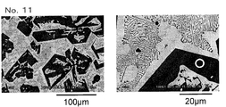
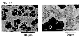
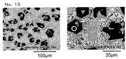
- 1 to 12 are electron micrographs (reflected electron images) obtained by observing a cross section of a coating layer of a wear-resistant component according to an embodiment of the present disclosure at 500 times (left figure) and 2000 times (right figure).
- the place that appears white is the parent phase (also called matrix) of the Cr—Ni alloy, and the place that appears gray or black is Cr carbide.
- Each of the photographs is a cross section of a Cr—Ni alloy that has undergone overlay welding, where the metal structure is a solidified structure and the Cr carbide is crystallized.
- massive, reticulated and vein-like Cr carbides can be seen.
- the composition of the carbide can be confirmed, for example, by quantitative analysis with an energy dispersive X-ray analyzer.
- Cr carbide means what contained the most Cr by mass% in the quantitative analysis results.
- the above-mentioned massive Cr carbide plays an important role in improving wear resistance.
- the size of the massive Cr carbide is preferably large.
- a size such that a circle of 7 ⁇ m or more can be drawn in the carbide is preferable, and a circle of 10 ⁇ m or more is more preferable in the carbide.
- a portion indicated by an arrow in FIG. 3 is a portion that has a color tone different from that of the surrounding area and appears black. This indicates that the black portion and the surrounding (gray) portion have different carbide forms.
- the portion indicated by the arrow is M 7 C 3 type Cr carbide and the surrounding area is M 23 C 6 type Cr carbide.
- the massive Cr carbide needs to be dispersed in a region (surface layer region) within a depth of 0.2 mm from the outermost surface of the coating layer. This is because the surface layer region requires the most wear resistance.
- the visual field area ratio of the massive Cr carbide (the massive carbide capable of attaching a circle having a diameter of 5 ⁇ m in the carbide) found in the surface region is 15 to 45% in 0.25 mm 2 .
- the surface layer region is a region where abrasion resistance is most necessary. If the field area ratio of the massive Cr carbide is less than 15% in this surface layer region, the wear resistance tends to be greatly reduced, and if it exceeds 45%, the wear resistance improving effect tends to be saturated. . Therefore, it is preferable to set the visual field area ratio of the massive Cr carbide found in the surface layer region to be in the range of 15 to 45%.
- the visual field area ratio of the massive Cr carbide seen in the surface layer region is in the range of 20 to 30%.
- the viewing area to be observed is preferred The wider, a large difference in observation be observed in more than 0.25 mm 2 is not, it is sufficient to observe the bulk Cr carbide in the range of 0.25 mm 2 is there.
- the visual field to be observed it is preferable to observe a certain range. For example, it is sufficient to observe one range of 0.25 mm 2 .
- the entire wear-resistant part may be a Cr—Ni alloy, but from the viewpoint of mechanical properties required in addition to corrosion resistance and wear resistance, the entire part is manufactured from another metal material.
- the Cr—Ni alloy coating layer may be formed only on the portions that require corrosion resistance and wear resistance.
- the base metal is steel for hot molds specified by JIS, and the metal material suitable for each application such as alloy tool steel and various stainless steels for screw pumps. Should be selected.
- the base metal and the Cr-Ni alloy are dissimilar alloys, the Cr-Ni alloy and the base metal melt and mix with the heat input during the build-up, and the Cr-Ni alloy is diluted by the base metal.
- the composition of the Cr—Ni based alloy changes between the base material side and the surface side.
- the C component contained in the Cr—Ni alloy decreases, so the size and amount of the above-mentioned massive Cr carbide also decreases, and wear resistance In some cases, it is not possible to sufficiently obtain massive Cr carbides that are effective for the above.
- the composition of the surface layer region of the coating layer is important.
- a method for confirming this is a method of analyzing characteristic X-rays generated by irradiating an object with an electron beam, such as EDX (energy dispersive X-ray analyzer) and WDX (wavelength dispersive X-ray analyzer).
- EDX energy dispersive X-ray analyzer
- WDX wavelength dispersive X-ray analyzer
- an analysis result having a value as described above is obtained for the composition.
- the wear resistance is lowered or the corrosion resistance is lowered.
- the acceleration voltage it is preferable to set the acceleration voltage to 15 keV and to analyze within a certain range from the surface side of the coating layer. For example, about 0.25 mm 2 is sufficient.
- the shape of the outermost layer is not flat where WDX analysis is possible, the outermost layer may be processed flat within a range of 0.2 mm to perform quantitative analysis.
- the surface layer region of the Cr—Ni alloy coating layer formed on the surface of the base material has a metal structure having a massive Cr boride.
- the present disclosure will be described below with reference to the drawings.
- the metal structure of the coating layer of the present disclosure will be described.
- 13 to 16 are electron micrographs (reflection electron images) obtained by observing the cross section of the surface layer region of the coating layer of the wear-resistant component according to the embodiment of the present disclosure at 500 times (upper stage) and 2000 times (lower stage). is there.
- the place that appears white or gray is the parent phase of the Cr—Ni alloy, and the place that appears dark gray or black is Cr boride.
- the metal structure is a solidified structure, and the Cr boride is crystallized.
- Cr borides of different sizes can be seen in the 2000 ⁇ photomicrograph.
- a typical massive Cr boride is a boride in which a circle having a diameter of 3 ⁇ m is attached and has an elongated shape with a substantially linear outer shape.
- the massive Cr boride in the present invention has a size capable of drawing a circle having a diameter of 3 ⁇ m or more on the inner side in cross-sectional observation. According to the investigation by the inventors, this massive Cr boride has been confirmed to be a plate-like structure having a cross section of a straight and long shape in the micrograph.
- the composition of the boride can be confirmed by, for example, quantitative analysis with an energy dispersive X-ray analyzer (EDX).
- EDX energy dispersive X-ray analyzer
- the Cr boride is one in which B is detected in the quantitative analysis result by EDX and the largest amount of Cr is included in the metal elements excluding B.
- the above-described massive Cr boride plays an important role in improving wear resistance.
- the size of the massive Cr boride should be large. For example, a size such that a circle of 5 ⁇ m or more can be drawn in the carbide is preferable, and a circle of 10 ⁇ m or more is more preferable in the carbide. The size that can be drawn is good.
- the massive Cr boride needs to be dispersed in a region (surface layer region) within a depth of 0.2 mm from the outermost surface of the coating layer. This is because the surface layer region requires the most wear resistance.
- the visual field area ratio of the massive Cr boride (the massive Cr boride having a diameter of 3 ⁇ m in the boride) found in the surface region is 5 to 35% in 0.25 mm 2.
- the surface layer region is a region where abrasion resistance is most necessary.
- the visual field area ratio of the massive Cr boride found in the surface layer region is in the range of 5 to 35%.
- the visual field area ratio of the massive Cr boride found in the surface layer region is in the range of 20 to 30%.
- field area to observe preferred The wider, no significant difference on the observation be observed in more than 0.25 mm 2, sufficient to observe the bulk Cr borides in the range of 0.25 mm 2 It is.
- the visual field to be observed it is preferable to observe a certain range. For example, it is sufficient to observe one range of 0.25 mm 2 .
- the entire wear-resistant part may be a Cr—Ni alloy, but from the viewpoint of mechanical properties required in addition to corrosion resistance and wear resistance, the base material of the part is made of another metal material.
- a Cr—Ni alloy coating layer may be formed only on the parts that are manufactured and require corrosion resistance and wear resistance.
- the base metal is steel for hot molds specified by JIS, and the metal material suitable for each application such as alloy tool steel and various stainless steels for screw pumps. Should be selected.
- the base metal and the Cr-Ni alloy are dissimilar alloys, the Cr-Ni alloy and the base metal melt and mix with the heat input during the build-up, and the Cr-Ni alloy is diluted by the base metal.
- the composition of the Cr—Ni based alloy changes between the base material side and the surface side.
- the B component in the base metal is less than that of the Cr—Ni alloy, the B component contained in the Cr—Ni alloy decreases, so the size and amount of the above-mentioned massive Cr boride also decreases, and wear resistance In some cases, it is not possible to sufficiently obtain a massive Cr boride having an effect on properties.
- the thickness of the coating layer varies depending on the application, but it is sufficient if the distance from the boundary between the coating layer and the base material to the outermost surface of the coating layer is approximately 5 to 15 mm.
- the “Cr—Ni-based alloy” refers to an alloy that has the largest amount of Cr among the contained elements and is balanced by Ni.
- the coating layer of the present disclosure may be affected by the components constituting the base material, the composition of the surface layer region of the coating layer is important.
- a method for confirming this there is a method of analyzing characteristic X-rays generated by irradiating an object with an electron beam, such as EDX (energy dispersive X-ray analyzer) and WDX (wavelength dispersive X-ray analyzer).
- EDX energy dispersive X-ray analyzer
- WDX wavelength dispersive X-ray analyzer
- an analysis result having a value as described above is obtained for the composition.
- the balance is Ni and inevitable impurities.
- the wear resistance is lowered or the corrosion resistance is lowered.
- the shape of the outermost surface is not flat where WDX analysis is possible, the outermost surface may be processed flat within a range of 0.2 mm to perform quantitative analysis.
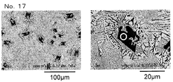
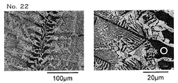
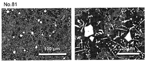
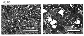
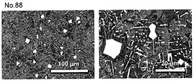
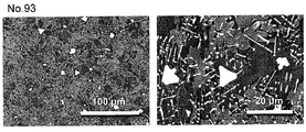
- FIG. 17 to 28 are cross-sectional views of the surface layer region of the coating layer of the wear-resistant component (example of the present invention) according to an embodiment of the present invention, 500 times (left side) and 2000 times (right side) using a scanning electron microscope (SEM). ) Is an image (reflected electron image) when observed in FIG.
- SEM scanning electron microscope
- the dark gray and light gray places are the base (matrix) of the Cr—Ni alloy, dark gray indicates the ferrite phase and light gray indicates the austenite phase.
- the phase that appears white is Nb-based carbide.
- the tree-like or lump-like black portion visible in the light gray austenite phase is Cr-based carbide.
- Each photograph is a cross-section of a Cr—Ni alloy that has undergone overlay welding, the metallographic structure is a solidified structure, and Nb-based carbides and Cr-based carbides are crystallized.
- the Nb-based carbides appear in the matrix as eutectic, such as rods, dots, feathers, dendrites, or lumps, in a 2000 ⁇ micrograph.
- the composition of each carbide can be confirmed, for example, by quantitative analysis with an energy dispersive X-ray analyzer.
- the Nb-based carbide means a substance in which C is detected in the result of the quantitative analysis, and Nb is contained most in mass% among the metal elements excluding C.
- the Cr-based carbide means a substance in which C is detected from the quantitative analysis results and the largest amount of Cr is included among the metal elements excluding C.
- the Nb-based carbide described above plays an important role in improving wear resistance.
- the Nb-based carbide has a lump-like, eutectic structure, or a rod-like, dot-like, feathery, or dendritic structure dispersed in the alloy on the network.
- an increase in the area of carbides in the alloy is also a factor for improving wear resistance.
- the field-of-view area ratio of the Nb-based carbide found in the surface layer region is 5 to 30% in 0.25 mm 2 .
- the surface layer region is a region where abrasion resistance is most necessary. If the field area ratio of the Nb-based carbide is less than 5% in this surface layer region, the wear resistance tends to be greatly reduced, and if it exceeds 30%, the amount of Nb and C in the alloy increases. The amount of Cr is reduced, and the corrosion resistance tends to decrease. For this reason, it is preferable to set the visual field area ratio of Nb-based carbides found in the surface layer region in the range of 5 to 30%.
- the field-of-view area ratio of Nb-based carbides found in the surface layer region is in the range of 5 to 20%.
- the viewing area to be observed is preferred The wider, a large difference in observation be observed in more than 0.25 mm 2 is not, it is sufficient to observe the Nb carbides in the range of 0.25 mm 2 is there.
- the visual field to be observed it is preferable to observe a certain range. For example, it is sufficient to observe one range of 0.25 mm 2 .
- the entire wear-resistant part may be a Cr—Ni alloy, but from the viewpoint of mechanical properties required in addition to corrosion resistance and wear resistance, the entire part is manufactured from another metal material.
- the Cr—Ni alloy coating layer may be formed only on the portions that require corrosion resistance and wear resistance.
- the base metal is steel for hot molds specified by JIS, and the metal material suitable for each application such as alloy tool steel and various stainless steels for screw pumps. Should be selected.
- the base material and the coating layer hereinafter also referred to as “Cr—Ni alloy” are dissimilar alloys, the Cr—Ni alloy and the base material melt and mix with the heat input at the time of overlaying, and Cr -Ni-based alloy is diluted by the base material.
- the composition of a coating layer will change with a base material side and a surface side according to the material of a base material.
- the C component in the base metal is less than that of the Cr—Ni alloy, the C component contained in the Cr—Ni alloy decreases, so the size and amount of the Nb carbide described above also decreases, and wear resistance In some cases, it is not possible to sufficiently obtain Nb-based carbides that are effective in properties.
- the effect of dilution by the base material is reduced as the part is applied later, and the vicinity of the surface
- a Nb-based carbide having a sufficient size and amount can be obtained.
- the area ratio of the Nb-based carbide in the surface layer region is made larger than that of the Nb-based carbide on the base material side so that the Nb-based carbide in the surface layer region secures an area ratio that contributes to improvement in wear resistance. It ’s fine.
- the thickness of the coating layer varies depending on the application, but it is sufficient if the distance from the boundary between the coating layer and the base material to the outermost surface of the coating layer is approximately 5 to 15 mm.
- the “Cr—Ni-based alloy” referred to in the present invention refers to an alloy containing the largest amount of Cr among the contained elements, Ni, Nb and C, and optionally Fe. Further, Si, Mn, Al, Sn, and Cu are also included in the scope of the “Cr—Ni alloy” within the range defined by the present invention.
- the coating layer of the present disclosure may be affected by the components constituting the base material, the composition of the surface layer region of the coating layer is important.
- a method for confirming this is a method of analyzing characteristic X-rays generated by irradiating an object with an electron beam, such as EDX (energy dispersive X-ray analyzer) and WDX (wavelength dispersive X-ray analyzer).
- EDX energy dispersive X-ray analyzer
- WDX wavelength dispersive X-ray analyzer
- an analysis result having a value as described above is obtained for the composition.
- the wear resistance is lowered or the corrosion resistance is lowered.
- the acceleration voltage it is preferable to set the acceleration voltage to 15 kV and to analyze within a certain range from the surface side of the coating layer. For example, about 0.25 mm 2 is sufficient.
- the shape of the outermost layer is not flat where WDX analysis is possible, the outermost layer may be processed flat within a depth of 0.2 mm to perform quantitative analysis.
- a component X contains x mass% in an alloy used for overlaying a coating layer and y mass% in a matrix material, and the ratio of the matrix material mixed in the coating layer after overlaying (dilution rate) ) Is P%, the amount of the component Xn in the outermost layer when n layers of overlaying are repeated in the height direction can be obtained by the following equation 1.
- Xn x ⁇ ⁇ 1 ⁇ (P / 100) n ⁇ + y ⁇ (P / 100) n (Formula 1) Therefore, calculating the amount of each component in the surface layer region of the coating layer after overlaying, assuming in advance such as the composition of the base material that forms the coating layer, the dilution rate at the time of overlaying, the number of overlays, What is necessary is just to make it become the range of the composition prescribed
- the overlaying alloy powder for producing the surface layer region (coating layer) of the present disclosure can be obtained by, for example, a water atomizing method or a gas atomizing method.
- a gas atomization method for obtaining a more clean and homogeneous composition / spherical particles for building-up powder applications.
- PTA Pullasma transfer arc
- a particle size range of 63 ⁇ m or more and 250 ⁇ m or less may be extracted and used.
- the alloy powder for build-up needs to move smoothly because it flows in the pipeline to the construction part at the tip of the welding torch.
- the alloy powder obtained by gas atomization is preferable because it is spherical and has good fluidity.
- the obtained overlay welding material may be used as it is as a wear-resistant part constituting various devices as it is, but the dimensions and shape of the coating layer are flattened in consideration of connection to other members. It is also possible to further implement a shaping process for shaping the wear-resistant part. Examples of the shaping means include cutting with a milling machine and polishing with a grindstone.
- the alloy powder obtained by performing the above-described atomizing process or further through a classification process can obtain a desired compact by performing a powder molding process.
- a powder molding method for example, in the case of a metal powder injection molding method, a material obtained by kneading plastic powder and wax as a binder into alloy powder to give fluidity and moldability to a mold with an injection molding machine A powder molding step of filling and molding and a degreasing step of removing the binder remaining in the obtained molded body can be performed.
- the molded body is immersed in a solvent or heated in a predetermined atmosphere.
- a sintering process is performed in which the compact is subjected to a sintering heat treatment at a temperature lower than the solidus temperature of the alloy to form a powder sintered body.
- the sintering heat treatment method There is no particular limitation on the sintering heat treatment method, and a conventional method can be used.
- the degreasing process and the sintering process are performed collectively by adjusting the temperature and atmosphere at the time before reaching the sintering temperature in this sintering process. You can also.
- a hot isostatic pressing (HIP) treatment under a condition of less than the solidus temperature of the alloy and not less than 500 atmospheres and not more than 3000 atmospheres. If a rod-shaped product is formed as a powder compact, this can be applied as, for example, an electrode rod of an arc welder and used for overlay welding on a desired substrate.
- HIP hot isostatic pressing
- wear-resistant parts of the present disclosure have both corrosion resistance and wear resistance
- automobile members for example, fuel injection device members, roller chain members, turbocharger members, engine exhaust system members, bearing members
- Railway related members for example, bearing members, pantograph members
- rolling bearings and sliding bearing members for example, linear bearing members, windmill bearing members, water wheel bearing members, ventilation fan bearing members, mixing drum bearing members, compressor bearing members, elevators
- Bearing members escalator bearing members, planetary probe bearing members
- construction equipment members for example, endless track members, mixing drum members
- ships and submarine members for example, screw members
- environmental equipment members for example, Garbage incinerator components, crushing machines
- bicycles motorcycles and Water bike members
- Water bike members for example, roller chain members, sprocket members
- machining device members for example, dies, rolling rolls, cutting tool members
- oil well equipment members for example, rotating machines (compressors, pumps)
- Members for example, rotating machines (compressors, pumps)
- Members for example, bearings)
- FIG. 30 (a) is an example of the wear-resistant part of the present invention, and is a schematic cross-sectional view of a screw pump used for transporting fluid such as crude oil including earth and sand.
- a coating layer for improving wear resistance is formed on a screw surface and a casing surface that come into contact with a fluid to be conveyed, or on a pipe inner surface connected to a suction port or a discharge port (not shown). Is done.
- a wear-resistant part having a coating layer defined in the present invention can be suitably used.
- the said coating layer can be manufactured with the form of the overlay welding material.
- FIG. 30 (b) is an example of the wear-resistant part of the present invention, and is a schematic sectional view of an injection mold.
- wear resistance is applied to the mold base surface that comes into contact with molten plastic or a mixture of metal powder and binder, which is filled in the space provided between the upper mold and the lower mold.
- a coating layer for improving the thickness is formed.
- a wear-resistant part having a coating layer defined in the present invention can be suitably used.
- the said coating layer can be manufactured with the form of the overlay welding material.
- FIG. 30 (c) is an example of the wear-resistant component of the present invention, and is a schematic cross-sectional view of a crushing machine called a jaw crusher that crushes rocks, concrete waste materials, and the like between rocking tooth plates.
- a coating layer for improving wear resistance is formed on the surfaces of a fixed tooth plate and a movable tooth plate that are in contact with an object to be crushed such as rocks.
- a wear-resistant part having a coating layer defined in the present invention can be suitably used.
- the said coating layer can be manufactured with the form of the overlay welding material.
- the present disclosure will be described more specifically with reference to examples and comparative examples. Note that the present disclosure is not limited to these examples.
- the corrosion resistance and wear resistance of the alloy powder having the composition shown in Table 1 were evaluated on the assumption that a coating layer was built on a SUS304 base material with a PTA overlay welding apparatus. Therefore, the mixed raw materials were melted by a high-frequency melting method (melting temperature 1500 ° C. or higher, in a reduced pressure Ar atmosphere), and then the molten metal was cast to produce a cast molded body of a Cr—Ni alloy simulating a coating layer.
- the mold to be used is selected to have an elongated cylindrical shape with a diameter of about 20 mm, and the structure of the cast molded body becomes a rapidly cooled structure close to the overlay weld bead. I did it.
- the molten base material is mixed into the built-up Cr—Ni based alloy, and the components of the Cr—Ni based alloy are diluted by the base material.
- the C component in the base material is less than that of the original Cr—Ni alloy, the C component contained in the Cr—Ni alloy after build-up is reduced, and the massive Cr carbide having an effect on wear resistance You may not get enough.
- a cast molded body having a composition that was supposed to finally appear in the vicinity of the outermost surface of the coating layer was prepared and evaluated without using the above-described alloy powder of Table 1 as a starting material.
- Table 2 shows the cylindrical surface of a cylindrical cast molded body that is ground and polished flatly from four sides to produce a square pillar-shaped test piece having a side of about 10 mm that shares the central axis with the cast molded body.
- the result of having analyzed the composition of this using WDX provided in EPMA is shown.
- no. 11, no. 14 and no. 16 is No. 16 respectively.
- the composition is based on the assumption that 1 to 3 overlaying materials are stacked several times, all of which are the same as the original composition. No. 12 and no. No.
- No. 1 is a composition when the overlay material is diluted with SUS304 base material.
- 12 is a composition when it is assumed that approximately 10% of the SUS304 base material is mixed in the Cr—Ni alloy after the build-up.
- No. 13 is No. It is a composition when it is assumed that the amount of heat input at the time of overlaying is greater than 12, and about 20% of the SUS304 base material is mixed.
- No. 15 is No.15. This is a composition when it is assumed that about 10% of the SUS304 base material is mixed in the Cr—Ni-based alloy after the overlaying material No. 2 is built up.
- No. 17 and no. No. 18 is No. This is a composition that is assumed to be increased or decreased by 0.5% in the same composition as in FIG. No.
- 19-No. No. 21 is No. 21.
- the composition is similar to 16, and the C is changed in the range of 1.5 to 2.5%.
- No. 22 is a composition in which C is 2.4% and Fe is increased to 25%.
- the surface of the test piece was observed for the presence and size of massive Cr carbide using a scanning electron microscope and EDX. The ratio of the total area of the massive Cr carbide seen in .25 mm 2 to the area of the observed region was determined as the visual field area ratio.
- the bulk Cr carbide size the longest value was used among the diameters of circles that could be drawn inside the bulk Cr carbide present in the observed region. Each result is shown in Table 3.
- No. The micrographs 11 to 22 are shown in FIGS.
- an abrasion resistance test was performed.
- a square columnar test piece having a side of about 10 mm was prepared from a cylindrical cast body, and the polished surface was used as a test surface in the same manner as the composition analysis.
- an abrasion resistance test it was set as the earth and sand abrasion resistance evaluation which is one of the most severe tests.
- Equipment for crude oil mining is subject to wear due to gravel in the crude oil in contact with it. Therefore, a soil wear test was performed as an abrasion resistance evaluation.
- the test method was compliant with ASTM standard G65. However, the test piece alone produced from the cast molded body did not satisfy the specified width of 25 mm.
- the test was performed with three test pieces arranged in parallel and fixed. After the test specimens of each composition were weighed before the test, the test silica sand was continuously supplied for 10 minutes between the contact surfaces with the rotating rubber disk pressed against the test specimen with a predetermined load. Thereafter, the weight of the test piece was measured to determine the mass change before and after the test, and the wear volume AVL (unit: mm 3 ) was calculated in consideration of the change in diameter due to the wear of the rubber disk accompanying the test. As a result of measuring the wear volume, “AVL ⁇ 180” was evaluated as A grade, “180 ⁇ AVL ⁇ 360” as B grade, and “360 ⁇ AVL” as C grade. The results of the earth and sand abrasion resistance evaluation are shown in Table 5.
- the corrosion resistance was also evaluated.
- the test piece for corrosion resistance evaluation was evaluated by preparing a square columnar test piece having a side of about 10 mm from a cylindrical cast body and polishing the surface in the same manner as the above-mentioned test piece for wear resistance evaluation.
- the equipment for crude oil mining assumed as an application field of the present invention is strong acid corrosion due to the influence of hydrogen sulfide contained in crude oil and hydrochloric acid generated by decomposition of inorganic chloride. Exposed to the environment. Then, the boiling sulfuric acid immersion test was implemented as corrosion resistance evaluation.
- test method conformed to JIS standard G0591: sulfuric acid corrosion test method for stainless steel, and the test solution was diluted with sulfuric acid having a pH of 1 with pure water to a concentration of 5% by mass.
- the test piece of each composition was weighed before the test and then immersed in a boiling test solution for 6 hours. Thereafter, the test piece mass is measured to determine the mass change before and after the test, and the value obtained by dividing the change by the test piece surface area and test time before the test is calculated as the corrosion rate m (unit: g / (m 2 ⁇ h)). did.
- Corrosion rate measurement results were evaluated as “m ⁇ 3 ⁇ 10 0 ” as A grade, “3 ⁇ 10 0 ⁇ m ⁇ 10 2 ” as B grade, and “10 2 ⁇ m” as C grade.
- the results of the corrosion resistance evaluation are shown in Table 5.
- FIG. 31 shows the test results of the corrosion rate m and the wear volume AVL of each test piece simulating the coating layer of the present invention and the overlay material of the comparative example.
- the numbers with circles on the side of each plot indicate the No. of each composition shown in Table 2. It corresponds to.
- FIGS. 11 has the smallest wear volume and, conversely, the highest degree of dilution.
- the wear volume of 13 is the largest.
- No. SEM observation images of Nos. 11 to 13 are shown in FIGS. In No. 11, the outer dimensions are generally larger than 100 ⁇ m, and massive Cr carbides displayed in dark gray are distributed. Next, No. 2 in FIG. 12, Cr carbide having a size exceeding 100 ⁇ m is observed. Less than 11. Further, in FIG. In No. 13, the size of the Cr carbide was about 50 ⁇ m, which was smaller, and many irregular dendritic portions were observed at the periphery of the carbide. Similarly, no. When comparing Nos. 14 and 15, no. The wear volume of 14 is smaller. No. 14 and 15 show SEM observation images of FIGS.
- the metal structure has Cr boride.
- a predetermined raw material is mixed to be a high-frequency melting method (melting temperature 1500 ° C. or higher, in a reduced pressure Ar atmosphere). Then, the molten metal was cast to prepare a cast molded body of a Cr—Ni alloy simulating the surface region of the coating layer.
- the mold to be used is selected to have an elongated cylindrical shape with a diameter of about 20 mm, and the structure of the cast molded body becomes a rapidly cooled structure close to the overlay weld bead. I did it.
- Table 6 shows that a cylindrical surface of a cylindrical cast molded body is ground and polished flatly from four sides, and a square columnar test piece having a side of about 10 mm sharing a central axis with the cast molded body is produced.
- the result of having analyzed the composition of this using WDX provided in EPMA is shown.
- the surface of the test piece was observed for the presence or size of massive Cr boride using a scanning electron microscope and EDX, The ratio of the total area of the massive Cr boride observed in 0.25 mm 2 to the area of the observed region was determined as the visual field area ratio.
- the results are shown in Table 7. Micrographs of the cross-sectional structure of each alloy are shown in FIGS. No. of this example. In Nos. 51 to 61, massive Cr borides were observed in the cross-sectional structure, and the Cr borides were large enough to draw a circle having a diameter of 3 ⁇ m on the inside.
- an abrasion resistance test was performed.
- a square columnar test piece having a side of about 10 mm was prepared from a cylindrical cast body, and the polished surface was used as a test surface in the same manner as the composition analysis.
- an abrasion resistance test it was set as the earth and sand abrasion resistance evaluation which is one of the most severe tests.
- Equipment for crude oil mining is subject to wear due to gravel in the crude oil in contact with it. Therefore, a soil wear test was performed as an abrasion resistance evaluation.
- the test method was compliant with ASTM standard G65. However, the test piece alone produced from the cast molded body did not satisfy the specified width of 25 mm.
- the test was performed with three test pieces arranged in parallel and fixed. After the test specimens of each composition were weighed before the test, the test silica sand was continuously supplied for 10 minutes between the contact surfaces with the rotating rubber disk pressed against the test specimen with a predetermined load. Thereafter, the weight of the test piece was measured to determine the mass change before and after the test, and the wear volume AVL (unit: mm 3 ) was calculated in consideration of the change in diameter due to the wear of the rubber disk accompanying the test. As a result of measuring the wear volume, “AVL ⁇ 180” was evaluated as A grade, “180 ⁇ AVL ⁇ 360” as B grade, and “360 ⁇ AVL” as C grade. The results of the earth and sand abrasion resistance evaluation are shown in Table 8.
- the corrosion resistance was also evaluated.
- the test piece for corrosion resistance evaluation was evaluated by preparing a square columnar test piece having a side of about 10 mm from a cylindrical cast body and polishing the surface in the same manner as the above-mentioned test piece for wear resistance evaluation.
- the equipment for crude oil mining assumed as an application field of the present invention is strong acid corrosion due to the influence of hydrogen sulfide contained in crude oil and hydrochloric acid generated by decomposition of inorganic chloride. Exposed to the environment. Then, the boiling sulfuric acid immersion test was implemented as corrosion resistance evaluation.
- test method conformed to JIS standard G0591: sulfuric acid corrosion test method for stainless steel, and the test solution was diluted with sulfuric acid having a pH of 1 with pure water to a concentration of 5% by mass.
- the test piece of each composition was weighed before the test and then immersed in a boiling test solution for 6 hours. Thereafter, the test piece mass is measured to determine the mass change before and after the test, and the value obtained by dividing the change by the test piece surface area and test time before the test is calculated as the corrosion rate m (unit: g / (m 2 ⁇ h)). did.
- Corrosion rate measurement results were evaluated as “m ⁇ 3 ⁇ 10 0 ” as A grade, “3 ⁇ 10 0 ⁇ m ⁇ 10 2 ” as B grade, and “10 2 ⁇ m” as C grade.
- the results of the corrosion resistance evaluation are shown in Table 8.
- FIG. 32 shows the test results of the corrosion rate m and the wear volume AVL of each test piece simulating the surface layer region of the coating layer of the present invention and the overlay material of the comparative example (shown in Table 4).
- the numbers in parentheses beside each plot indicate the No. of each composition shown in Table 6. It corresponds to.
- the corrosion resistance of the wear-resistant component of the present invention it is considered that the corrosion rate tends to increase as the visual field area ratio of the massive Cr boride increases.
- the overlay material No. In Nos. 31 to 36 there is no material that has achieved A grade in both corrosion resistance and earth and sand wear resistance.
- the alloy of the present invention realizes both corrosion resistance and wear resistance, and is excellent as a wear resistant part. It can be said that
- carbonized_material is demonstrated.
- the corrosion resistance and wear resistance of the alloy powder having the composition shown in Table 9 were evaluated on the assumption that a coating layer was built on a SUS304 base material with a PTA overlay welding apparatus. Therefore, the mixed raw materials were melted by a high-frequency melting method (melting temperature 1500 ° C. or higher, in a reduced pressure Ar atmosphere), and then the molten metal was cast to produce a cast molded body of a Cr—Ni alloy simulating a coating layer.
- the mold to be used is selected to have an elongated cylindrical shape with a diameter of about 20 mm, and the structure of the cast molded body becomes a rapidly cooled structure close to the overlay weld bead. I did it.
- the melted base material is mixed into the overlaying Cr—Ni based alloy, and the components of the Cr—Ni based alloy are diluted by the base material.
- the C component in the base material is less than the Cr—Ni alloy of the coating layer, the phase ratio of the carbide phase contained in the unit area of the Cr—Ni alloy after the build-up decreases, and wear resistance
- the size, distribution, number, or volume of Nb-based carbides that are effective in properties is less than expected.
- the alloy powder of Table 9 described above was not particularly limited as a starting material, and a cast molded body having a composition that was supposed to finally appear near the resurface of the coating layer was also produced and evaluated.
- the cooling rate of the cast body decreases as it goes from the outer surface in contact with the mold to the inside of the alloy.
- the build-up surface has a high cooling rate, so in this test, when taking out a test piece from the cast molded body, it was obtained from the outer surface in contact with the mold having a high cooling rate as much as possible.
- Table 10 shows a cylindrical column-shaped test piece having a side of about 10 mm that shares a central axis with the cast molded body by grinding and polishing the cylindrical surface of a cylindrical cast molded body flatly from four sides.
- Table 10 shows a cylindrical column-shaped test piece having a side of about 10 mm that shares a central axis with the cast molded body by grinding and polishing the cylindrical surface of a cylindrical cast molded body flatly from four sides.
- This is a composition assuming a composition in the vicinity of the outermost surface when the overlaying materials 71 to 76 are stacked several times, and all are the same as the original composition.
- no. No. 87 is No. 87.
- No. 88 is No. 88.
- 71 is a composition when the cladding material is diluted by about 10% with a SUS304 base material.
- No. 89 to 91 are compositions when the Cr amount is fixed to 50% and the amounts of C and Nb are changed.
- No. 92 has a composition of 35.0% Fe.
- No. No. 93 is No. 93.
- 71 is a composition of a comparative example in which the cladding material of 71 was diluted 20% with a SUS304 base material and Cr was below the lower limit.
- the surface of the test piece was observed for the presence or absence of Nb-based carbide using a scanning electron microscope (SEM) and EDX, and the size, The ratio of the total area of Nb-based carbides observed in 0.25 mm 2 to the area of the observed region was determined as the visual field area ratio.
- SEM scanning electron microscope
- EDX a scanning electron microscope
- an abrasion resistance test was performed.
- a square columnar test piece having a side of about 10 mm was prepared from a cylindrical cast body, and the polished surface was used as a test surface in the same manner as the composition analysis.
- the surface of the piping member used in the transport path through which the transported object such as crude oil flows is contained in the transported object that comes into contact with it. Receive. Therefore, an earth and sand abrasion test was carried out assuming that the solid material was quartz sand as an abrasion resistance evaluation.
- the test method conformed to ASTM standard G65.
- the test piece simulating the surface alloy in contact with the object to be transported is measured with the pre-test weight, and then the rotating rubber disk is pressed against the test piece with a predetermined load (64.5 N).
- silica sand simulating a solid was continuously supplied for 10 minutes under the condition of 350 g / min.
- the weight of the test piece was measured to determine the mass change before and after the test, and the wear volume AVL (unit: mm 3 ) of the test piece in consideration of the surface in contact with the conveyed object was calculated.
- AVL ⁇ 180” was evaluated as A grade
- “360 ⁇ AVL” as C grade.
- the results of soil and sand wear resistance evaluation are shown in Table 12.
- the corrosion resistance was also evaluated.
- the surface of piping members used in the transport path through which the transported material such as crude oil flows is hydrogen sulfide contained in the transported material in contact with it, hydrochloric acid generated by decomposition of inorganic chloride, etc. It is exposed to a strong acid corrosion environment due to the influence of corrosive components. Therefore, a boiling sulfuric acid immersion test was conducted assuming that the corrosive component is sulfuric acid as a strong acidity evaluation.
- the test method conformed to JIS standard G0591 a sulfuric acid corrosion test method for stainless steel, and a simulated solution of a corrosion component was prepared by diluting sulfuric acid having a pH of 1 with pure water to a concentration of 5% by mass.
- a test piece obtained by cutting and polishing a molded body having each composition was used. After measuring the pre-test weight of this test piece, it was immersed for 6 hours in a boiling corrosion component simulation solution.
- the mass of each test piece of the alloy corresponding to the surface of the piping member is measured to determine the mass change before and after the test, and the value obtained by dividing this by the test piece surface area and the test time before the test is the corrosion rate m (unit: g / (M 2 ⁇ h)).
- the corrosion rate measurement results were evaluated as “m ⁇ 3 ⁇ 10 0 ” as A grade, “3 ⁇ 10 0 ⁇ m ⁇ 1 ⁇ 10 2 ” as B grade, and “1 ⁇ 10 2 ⁇ m” as C grade. .
- the results of the corrosion resistance evaluation are shown in Table 12.
- FIG. 33 shows the test results of the corrosion rate m and the wear volume AVL of each test piece simulating the coating layer of the present invention and the overlay material of the comparative example (shown in Table 4).
- the numbers in parentheses beside each plot indicate the No. of each composition shown in Table 10 and Table 12. It corresponds to.
- the composition No. 1 of the present invention having the same composition as the alloy powder of Table 9 was used.
- both corrosion resistance and wear resistance were determined to be A grade, and all were good characteristics.
- no. No. 86 assuming a 10% dilution with respect to 86. No.
- no. Nos. 89 to 91 are compositions in which the composition of Cr is 50% and the amounts of Nb and C are changed. No. 89 with Nb and C increased compared to 89. In 90 and 91, the wear volume decreased and the wear resistance improved. This No. In Nos. 90 and 91, large massive No-based carbides are seen compared to others, and in particular, No. 1 with a large ratio of C to Nb. In 90, Cr-based carbides were also crystallized in the matrix, and it seems that these contributed to wear resistance.
- no. No. 92 has eutectic Nb-based carbides in the structure as shown in FIG. Among the 81 to 93 results, the abrasion resistance was the worst.
- the wear resistance of the alloy of the present invention is not limited to the amount of Nb-based carbides, but also Cr, Fe, which influences the crystallization form of Nb-based carbides during the solidification process of the material and the strength of the parent phase itself. It can be said that it is important to set the amount of Ni within an appropriate range.
- no. 92 is Comparative Example No. Compared with 31-36, it is not inferior, but equivalent or better.
Landscapes
- Engineering & Computer Science (AREA)
- Mechanical Engineering (AREA)
- Chemical & Material Sciences (AREA)
- Materials Engineering (AREA)
- Metallurgy (AREA)
- Organic Chemistry (AREA)
- Powder Metallurgy (AREA)
Priority Applications (1)
| Application Number | Priority Date | Filing Date | Title |
|---|---|---|---|
| JP2020509296A JP7459787B2 (ja) | 2018-03-28 | 2019-03-28 | 耐摩耗性部品 |
Applications Claiming Priority (6)
| Application Number | Priority Date | Filing Date | Title |
|---|---|---|---|
| JP2018-061098 | 2018-03-28 | ||
| JP2018061098 | 2018-03-28 | ||
| JP2018125314 | 2018-06-29 | ||
| JP2018-125314 | 2018-06-29 | ||
| JP2018157413 | 2018-08-24 | ||
| JP2018-157413 | 2018-08-24 |
Publications (1)
| Publication Number | Publication Date |
|---|---|
| WO2019189532A1 true WO2019189532A1 (ja) | 2019-10-03 |
Family
ID=68062203
Family Applications (1)
| Application Number | Title | Priority Date | Filing Date |
|---|---|---|---|
| PCT/JP2019/013492 Ceased WO2019189532A1 (ja) | 2018-03-28 | 2019-03-28 | 耐摩耗性部品 |
Country Status (2)
| Country | Link |
|---|---|
| JP (1) | JP7459787B2 (https=) |
| WO (1) | WO2019189532A1 (https=) |
Cited By (3)
| Publication number | Priority date | Publication date | Assignee | Title |
|---|---|---|---|---|
| WO2022064973A1 (ja) * | 2020-09-24 | 2022-03-31 | Jfeスチール株式会社 | 高疲労強度鋼の素材となる鋳片の清浄度評価方法及び高疲労強度鋼の製造方法 |
| CN117836542A (zh) * | 2021-08-05 | 2024-04-05 | 帝伯爱尔株式会社 | 油环 |
| EP4163409A4 (en) * | 2020-06-09 | 2024-07-31 | Hitachi, Ltd. | WEAR-RESISTANT ELEMENT AND MECHANICAL DEVICE |
Citations (5)
| Publication number | Priority date | Publication date | Assignee | Title |
|---|---|---|---|---|
| JPH01294844A (ja) * | 1988-05-24 | 1989-11-28 | Tocalo Co Ltd | 含塩化物環境下で優れた耐食性を示す溶接肉盛材料 |
| JPH04358054A (ja) * | 1991-06-03 | 1992-12-11 | Kobe Steel Ltd | 耐エロージョン性に優れた溶射用粉末材料および表面 被覆部品 |
| JPH0649573A (ja) * | 1990-12-28 | 1994-02-22 | Daido Steel Co Ltd | 高硬度ロール材 |
| JPH10110206A (ja) * | 1996-10-03 | 1998-04-28 | Praxair St Technol Inc | 炭化クロム−ニッケルクロム微粒化粉の製造方法 |
| JP2007277675A (ja) * | 2006-04-11 | 2007-10-25 | Nippon Steel Corp | 電気メッキ用コンダクターロール |
Family Cites Families (2)
| Publication number | Priority date | Publication date | Assignee | Title |
|---|---|---|---|---|
| JPH01230759A (ja) * | 1987-12-29 | 1989-09-14 | Showa Denko Kk | 溶射用複合粉末 |
| DE69509511T2 (de) | 1994-12-02 | 1999-12-23 | Toyota Jidosha K.K., Toyota | Hochchromhaltige Nickellegierung mit hervorragendem Widerstand gegen Verschleiss und Korrosion durch Blei sowie Motorventile |
-
2019
- 2019-03-28 WO PCT/JP2019/013492 patent/WO2019189532A1/ja not_active Ceased
- 2019-03-28 JP JP2020509296A patent/JP7459787B2/ja active Active
Patent Citations (5)
| Publication number | Priority date | Publication date | Assignee | Title |
|---|---|---|---|---|
| JPH01294844A (ja) * | 1988-05-24 | 1989-11-28 | Tocalo Co Ltd | 含塩化物環境下で優れた耐食性を示す溶接肉盛材料 |
| JPH0649573A (ja) * | 1990-12-28 | 1994-02-22 | Daido Steel Co Ltd | 高硬度ロール材 |
| JPH04358054A (ja) * | 1991-06-03 | 1992-12-11 | Kobe Steel Ltd | 耐エロージョン性に優れた溶射用粉末材料および表面 被覆部品 |
| JPH10110206A (ja) * | 1996-10-03 | 1998-04-28 | Praxair St Technol Inc | 炭化クロム−ニッケルクロム微粒化粉の製造方法 |
| JP2007277675A (ja) * | 2006-04-11 | 2007-10-25 | Nippon Steel Corp | 電気メッキ用コンダクターロール |
Cited By (6)
| Publication number | Priority date | Publication date | Assignee | Title |
|---|---|---|---|---|
| EP4163409A4 (en) * | 2020-06-09 | 2024-07-31 | Hitachi, Ltd. | WEAR-RESISTANT ELEMENT AND MECHANICAL DEVICE |
| WO2022064973A1 (ja) * | 2020-09-24 | 2022-03-31 | Jfeスチール株式会社 | 高疲労強度鋼の素材となる鋳片の清浄度評価方法及び高疲労強度鋼の製造方法 |
| JPWO2022064973A1 (https=) * | 2020-09-24 | 2022-03-31 | ||
| JP7201124B2 (ja) | 2020-09-24 | 2023-01-10 | Jfeスチール株式会社 | 高疲労強度鋼の素材となる鋳片の清浄度評価方法及び高疲労強度鋼の製造方法 |
| CN117836542A (zh) * | 2021-08-05 | 2024-04-05 | 帝伯爱尔株式会社 | 油环 |
| CN117836542B (zh) * | 2021-08-05 | 2025-02-21 | 帝伯爱尔株式会社 | 油环 |
Also Published As
| Publication number | Publication date |
|---|---|
| JP7459787B2 (ja) | 2024-04-02 |
| JPWO2019189532A1 (ja) | 2021-04-08 |
Similar Documents
| Publication | Publication Date | Title |
|---|---|---|
| JP7695628B2 (ja) | Cr-Ni系合金、Cr-Ni系合金の製造方法および急冷凝固成形体 | |
| JP7185672B2 (ja) | 靱性及び耐摩耗性を有する多重硬質相含有鉄合金 | |
| EP2639323B1 (en) | Wear-resistant cobalt-based alloy and engine valve coated with same | |
| Ravi et al. | Microstructural evolution and wear behavior of carbon added CoCrFeMnNi multi-component alloy fabricated by mechanical alloying and spark plasma sintering | |
| EP2639324B1 (en) | High-toughness cobalt-based alloy and engine valve coated with same | |
| EP3202934A1 (en) | Two-phase alloy, product obtained using said two-phase alloy, and process for producing said product | |
| EP3488942A1 (en) | Roll outer layer material for rolling, and composite roll for rolling | |
| JP7459787B2 (ja) | 耐摩耗性部品 | |
| Veerappan et al. | Effect of copper on mechanical properties and corrosion behavior of powder metallurgy processed Ni–Co–Cr–Fe–Mn–Cu x high entropy alloy | |
| JP6481802B1 (ja) | Cr−Fe−Ni系合金製造物およびその製造方法 | |
| JP7524547B2 (ja) | Cr-Ni系合金部材およびその製造方法 | |
| US12312659B2 (en) | Wear-resistant member and mechanical device using same | |
| KR20230068340A (ko) | 용융 응고 성형용 Fe기 합금 및 금속 분말 | |
| Rdzawski | Effect of rare-earth metals addition on microstructure and properties of selected copper alloys | |
| JP7772102B2 (ja) | ステンレス鋼粉末、ステンレス鋼部材およびステンレス鋼部材の製造方法 | |
| JP7665324B2 (ja) | 耐摩耗性部材およびそれを用いた機械装置 | |
| JP2021195567A (ja) | 耐摩耗性部材およびそれを用いた機械装置 | |
| JP2020015925A (ja) | Cr基二相合金製造物およびその製造方法 | |
| JP7545820B2 (ja) | 耐摩耗性部材およびそれを用いた機械装置 | |
| JP2007196257A (ja) | 圧延用ロール | |
| JP6804777B2 (ja) | 耐食性評価用金属試験片の作製方法 | |
| Alvi | Effect of molybdenum and nickel on the interface between titanium carbide and high chromium white cast iron | |
| Zhao et al. | Synergistic improvement in wear and high-temperature oxidation resistance of Cr3C2 ceramic particles/heat-resistant stainless-steel composites | |
| Mostert | Cold-pressing and vacuum arc melting of γ-TiAl based alloys | |
| JP2007125565A (ja) | 遠心鋳造製耐摩耗性部材 |
Legal Events
| Date | Code | Title | Description |
|---|---|---|---|
| 121 | Ep: the epo has been informed by wipo that ep was designated in this application |
Ref document number: 19775041 Country of ref document: EP Kind code of ref document: A1 |
|
| ENP | Entry into the national phase |
Ref document number: 2020509296 Country of ref document: JP Kind code of ref document: A |
|
| NENP | Non-entry into the national phase |
Ref country code: DE |
|
| 122 | Ep: pct application non-entry in european phase |
Ref document number: 19775041 Country of ref document: EP Kind code of ref document: A1 |