WO2019187752A1 - 電動モータ - Google Patents
電動モータ Download PDFInfo
- Publication number
- WO2019187752A1 WO2019187752A1 PCT/JP2019/005545 JP2019005545W WO2019187752A1 WO 2019187752 A1 WO2019187752 A1 WO 2019187752A1 JP 2019005545 W JP2019005545 W JP 2019005545W WO 2019187752 A1 WO2019187752 A1 WO 2019187752A1
- Authority
- WO
- WIPO (PCT)
- Prior art keywords
- electric motor
- intermediate portion
- stator core
- straight
- teeth
- Prior art date
- Legal status (The legal status is an assumption and is not a legal conclusion. Google has not performed a legal analysis and makes no representation as to the accuracy of the status listed.)
- Ceased
Links
Images

Classifications
-
- H—ELECTRICITY
- H02—GENERATION; CONVERSION OR DISTRIBUTION OF ELECTRIC POWER
- H02K—DYNAMO-ELECTRIC MACHINES
- H02K1/00—Details of the magnetic circuit
- H02K1/06—Details of the magnetic circuit characterised by the shape, form or construction
- H02K1/12—Stationary parts of the magnetic circuit
- H02K1/14—Stator cores with salient poles
- H02K1/146—Stator cores with salient poles consisting of a generally annular yoke with salient poles
-
- H—ELECTRICITY
- H02—GENERATION; CONVERSION OR DISTRIBUTION OF ELECTRIC POWER
- H02K—DYNAMO-ELECTRIC MACHINES
- H02K2213/00—Specific aspects, not otherwise provided for and not covered by codes H02K2201/00 - H02K2211/00
- H02K2213/03—Machines characterised by numerical values, ranges, mathematical expressions or similar information
Definitions
- the present invention relates to an electric motor, and more particularly to an electric motor including a stator having a polygonal cross-sectional outer shape.
- the electromagnetic excitation force in the radial direction applied to the stator is known as a generation factor of vibration and noise in the electric motor.
- the radiated sound caused by the stator vibration has a larger proportion of the radial component than the rotational component, and the influence thereof is large. Therefore, as a means to suppress vibration and noise generated by the electromagnetic excitation force in the radial direction, a method of increasing the strength by fixing the stator with a resin mold or the like has been conventionally performed, which is effective in reducing vibration and noise. I give you.
- An electric motor of the present invention is an electric motor including a rotor and a stator core that is rotatably disposed outside the rotor and has a polygonal cross-sectional outer shape, and the stator core has an annular outer periphery And a plurality of tooth portions that protrude from the outer peripheral portion toward the rotor and are arranged along the rotation direction of the rotor, and the outer peripheral portion is a straight formed at a base portion of the tooth portion.
- the radial width W1 of the intermediate part is the radial direction of the straight part It is characterized by being set larger than the width W2 (W1> W2).
- an electric motor including a stator core having a cross-sectional outer shape formed in a polygonal shape
- a straight portion is formed at a teeth portion base portion of the stator core, and an intermediate portion having a bent portion is formed as an adjacent straight portion.
- the radial width W1 of the intermediate portion is set larger than the radial width W2 of the straight portion (W1> W2).
- the ratio (W1 / W2) of the radial width W1 of the intermediate portion and the radial width W2 of the straight portion may be set to 1.25 to 1.5.
- the ratio W1 / W2 may preferably be set in the vicinity of 1.25 (for example, about 1.3).
- the electric motor is provided with a winding wound around the teeth portion and accommodated in a slot formed between the teeth portions, thereby increasing the stator core mass and reducing the winding area in the slot.
- the ratio (W1 / W2) of the radial width W1 of the intermediate portion and the radial width W2 of the straight portion (W1 / W2) is 1.25 to 1.5 so that the stress of the intermediate portion can be kept low while suppressing. It may be set to.
- an electric motor including a stator core whose cross-sectional outer shape is formed in a polygonal shape, a straight portion formed at a base portion of a teeth portion and an adjacent straight portion at an outer peripheral portion of the stator core.
- An intermediate portion having a bent portion provided so as to connect the intermediate portion, and the radial width W1 of the intermediate portion is set larger than the radial width W2 of the straight portion (W1> W2).
- Stator core strength can be improved, and vibration and noise can be effectively reduced without the resin molding of the stator.
- An object of the following embodiments is to effectively reduce vibration and noise without using a resin mold for the stator in an electric motor including a stator having a polygonal cross section.
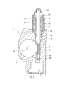
- FIG. 1 is a sectional view showing a configuration of a motor unit 1 using an electric motor according to an embodiment of the present invention.
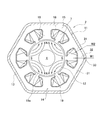
- FIG. 2 is a sectional view showing a configuration of an electric motor used in the motor unit of FIG. It is.
- a motor unit 1 in FIG. 1 includes an electric motor 2 (hereinafter abbreviated as a motor 2) and a speed reduction mechanism (transmission mechanism) 3.
- the rotation of the rotating shaft 4 of the motor 2 is shifted within the speed reduction mechanism unit 3 and is output from the output shaft 5 to the outside of the unit.
- the motor 2 is a brushless motor, and is composed of a stator 11 and a rotor 12 rotatably disposed in the stator 11 as shown in FIGS.
- the stator 11 includes a bottomed cylindrical motor housing 13 and a stator core 14 fixed to the inner surface of the motor housing 13.
- the stator core 14 is formed by laminating a plurality of plates made of a magnetic material, and has an annular outer peripheral portion 15 and teeth protruding from the outer peripheral portion 15 toward the center direction (radially inner side) ( Teeth portion) 16.
- the teeth 16 are formed radially toward the rotor 12.
- a slot 17 is provided between adjacent teeth 16, and the motor 2 has a 6-slot configuration.
- a winding 18 is wound around the outer periphery of the tooth 16. The winding 18 is accommodated in the slot 17.
- the outer periphery 15 of the stator core 14 has a hexagonal shape (polygonal shape).
- the term “annular” in the present invention means not only an annular shape but also a polygonal contour shape.
- the outer peripheral portion 15 includes a straight straight portion 31 and an intermediate portion 32 provided between adjacent straight portions.
- the straight portion 31 is formed integrally with the tooth 16 on the base portion (radially outer peripheral side) of the tooth 16.
- the intermediate part 32 is provided between the teeth 16 so as to connect the adjacent straight parts 31 to each other.
- the straight portion 31 is provided perpendicular to the teeth 16.
- the intermediate portion 32 has a bent portion 33 bent in a “dog leg” shape along the circumferential direction (rotor rotation direction).
- the straight portion 31 and the intermediate portion 32 are connected without a break, and the outer peripheral portion 15 is integrally formed without dividing the entire periphery.
- a rotor 12 is inserted inside the stator 11.
- the rotor 12 includes a rotating shaft 4 and a magnet 19 fixed to the rotating shaft 4.
- One end side of the rotating shaft 4 is rotatably supported by a bearing 21 provided at the end of the motor housing 13.
- the magnet 19 is a rare earth permanent magnet such as neodymium, dysprosium, or samarium.
- the magnet 19 is magnetized to 4 poles, and the motor 2 is a brushless motor having a 4 pole 6 slot configuration.
- the speed reduction mechanism unit 3 includes a worm (driving gear) 5 formed on the rotating shaft 4 and a worm wheel (driven gear) 6 that meshes with the worm 5.
- the speed reduction mechanism unit 3 is accommodated in a gear case 22 formed of synthetic resin or aluminum die casting. As shown in FIG. 1, one end opening side of the motor housing 13 is fixed to the gear case 22.
- the rotating shaft 4 of the motor 2 extends into the gear case 22.
- the rotary shaft 4 is rotatably supported by a bearing 23 and a bearing 24 provided in the gear case 22.
- the worm wheel 7 is fixed to the output shaft 5.
- the output shaft 5 rotates together with the worm wheel 7.
- the cross-sectional outer shape (outer shape of the cross section perpendicular to the rotating shaft 4) of the stator core 14 is a polygonal shape (in this embodiment, a hexagon).
- a polygonal stator when used, stress concentrates on an intermediate portion between adjacent teeth because of its structure. Therefore, the most stress is generated in the intermediate portion (particularly the bent portion) with respect to the electromagnetic excitation force that causes vibration and noise. With respect to the excitation force, the higher the strength of the stator, the more the operation noise can be suppressed. In the case of a polygonal stator, increasing the strength of the intermediate portion is effective as a countermeasure against vibration and noise.
- the thickness dimension W1 of the intermediate portion 32 is set larger than the thickness dimension W2 of the straight portion 31 (W1> W2).
- the greater the thickness dimension W1 of the intermediate portion 32 the greater the strength.
- the size of the stator also increases, and the motor becomes larger and heavier.
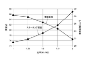
- the inventors changed the dimensional ratio of the straight part and the intermediate part in the polygonal stator core to change the radial electromagnetic excitation force teeth 16. , The stator mass, and the winding area (the area that can accommodate the winding in one slot) were compared.
- the stress is reduced as a whole by increasing the dimension W1 of the intermediate portion 32 and increasing the dimension ratio W1 / W2. Therefore, from the viewpoint of stress, it is desirable that the dimensional ratio W1 / W2 between the straight portion 31 and the intermediate portion 32 is as large as possible. That is, in relation to the stator core mass and the winding area, it is desirable that the dimensional ratio W1 / W2 is small, and in relation to stress, it is desirable that the dimensional ratio W1 / W2 is large, and the two are in a trade-off relationship. is there.
- the dimensional ratio W1 / W2 is preferably in the range of 1.25 to 1.5, and particularly around 1.25. Is preferred.
- the stator core strength is suppressed while suppressing the increase in the stator core mass and the decrease in the winding area. It becomes possible to improve. That is, with this setting, it is possible to satisfactorily satisfy three of the stator core mass, the winding area, and the stator core strength with a good balance. As a result, in an electric motor including a stator having a polygonal cross-sectional outer shape, vibration and noise can be effectively reduced without using a resin mold for the stator.
- the present invention is not limited to the above-described embodiment, and various modifications can be made without departing from the scope of the invention.
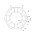
- the stator core 14 having the bent intermediate portion 32 has been described as an example, but the stator core 34 in which a portion of the intermediate portion 32 has a straight shape as shown in FIG.
- the present invention is applicable.
- the bent portions 35 are formed at both ends of the intermediate portion 32 along the circumferential direction (rotor rotation direction), and stress concentrates on the portions.
- stator core mass, winding area, and stator core strength are balanced by setting the dimensional ratio W1 / W2 between the straight portion 31 and the intermediate portion 32 within the range of 1.25 to 1.5 as described above. It can be satisfactorily satisfied.
- the number of slots of the stator 11 is not limited to six, and the present invention can be applied to motors of three slots, four slots, eight slots, and nine slots. With the difference in the number of slots, the outer shape of the stator core 14 also becomes a polygon such as a triangle, a quadrangle, or an octagon. Furthermore, although the brushless motor was shown as embodiment of this invention, this invention is applicable also to a motor with a brush.
- the motor 2 has an SPM (Surface Permanent Magnet) structure in which the magnet 19 is directly opposed to the stator core 14, an IPM (Interior Permanent Magnet) having a steel rotor core on the rotor side and a magnet embedded therein.
- SPM Surface Permanent Magnet
- IPM Interior Permanent Magnet
- the present invention can also be applied to a motor having a configuration.
- the brushless motor according to the present invention can be widely applied not only to an in-vehicle motor of an automobile but also to an electric motor used for home appliances, industrial machines and the like.
Landscapes
- Engineering & Computer Science (AREA)
- Power Engineering (AREA)
- Iron Core Of Rotating Electric Machines (AREA)
Priority Applications (1)
| Application Number | Priority Date | Filing Date | Title |
|---|---|---|---|
| EP19776809.6A EP3780341A4 (en) | 2018-03-27 | 2019-02-15 | Electric motor |
Applications Claiming Priority (2)
| Application Number | Priority Date | Filing Date | Title |
|---|---|---|---|
| JP2018-059289 | 2018-03-27 | ||
| JP2018059289A JP2019176542A (ja) | 2018-03-27 | 2018-03-27 | 電動モータ |
Publications (1)
| Publication Number | Publication Date |
|---|---|
| WO2019187752A1 true WO2019187752A1 (ja) | 2019-10-03 |
Family
ID=68058020
Family Applications (1)
| Application Number | Title | Priority Date | Filing Date |
|---|---|---|---|
| PCT/JP2019/005545 Ceased WO2019187752A1 (ja) | 2018-03-27 | 2019-02-15 | 電動モータ |
Country Status (3)
| Country | Link |
|---|---|
| EP (1) | EP3780341A4 (enExample) |
| JP (1) | JP2019176542A (enExample) |
| WO (1) | WO2019187752A1 (enExample) |
Cited By (1)
| Publication number | Priority date | Publication date | Assignee | Title |
|---|---|---|---|---|
| CN114825681A (zh) * | 2021-01-27 | 2022-07-29 | 莱克电气股份有限公司 | 电机与毛发护理器具 |
Families Citing this family (2)
| Publication number | Priority date | Publication date | Assignee | Title |
|---|---|---|---|---|
| JP7121071B2 (ja) * | 2020-05-22 | 2022-08-17 | 富士電機株式会社 | 回転電機 |
| CN111884367A (zh) * | 2020-08-31 | 2020-11-03 | 广东肇庆爱龙威机电有限公司 | 无刷直流电机 |
Citations (8)
| Publication number | Priority date | Publication date | Assignee | Title |
|---|---|---|---|---|
| JPS6132753U (ja) * | 1984-07-26 | 1986-02-27 | 三菱電機株式会社 | 直流機 |
| JPS6142237A (ja) * | 1984-07-31 | 1986-02-28 | Matsushita Electric Ind Co Ltd | ステツプモ−タ |
| JPS61134650U (enExample) * | 1985-02-05 | 1986-08-22 | ||
| JPH03159531A (ja) * | 1989-08-21 | 1991-07-09 | Switched Reluctance Drives Ltd | レラクタンス回転機 |
| JP2003259572A (ja) * | 2002-02-27 | 2003-09-12 | Minebea Co Ltd | 回転電機 |
| JP2013066313A (ja) * | 2011-09-19 | 2013-04-11 | Nippon Densan Corp | モータおよびモータの製造方法 |
| JP2016021822A (ja) | 2014-07-15 | 2016-02-04 | 株式会社ミツバ | ブラシレスモータ |
| JP2017135861A (ja) * | 2016-01-28 | 2017-08-03 | 日本電産サンキョー株式会社 | ステータおよびステータの製造方法 |
Family Cites Families (2)
| Publication number | Priority date | Publication date | Assignee | Title |
|---|---|---|---|---|
| JP2009106047A (ja) * | 2007-10-23 | 2009-05-14 | Hitachi Ltd | 電動機およびそれを備えた車両駆動装置 |
| DE202016104036U1 (de) * | 2015-08-07 | 2016-10-26 | Johnson Electric S.A. | Kühlgerät |
-
2018
- 2018-03-27 JP JP2018059289A patent/JP2019176542A/ja active Pending
-
2019
- 2019-02-15 EP EP19776809.6A patent/EP3780341A4/en active Pending
- 2019-02-15 WO PCT/JP2019/005545 patent/WO2019187752A1/ja not_active Ceased
Patent Citations (8)
| Publication number | Priority date | Publication date | Assignee | Title |
|---|---|---|---|---|
| JPS6132753U (ja) * | 1984-07-26 | 1986-02-27 | 三菱電機株式会社 | 直流機 |
| JPS6142237A (ja) * | 1984-07-31 | 1986-02-28 | Matsushita Electric Ind Co Ltd | ステツプモ−タ |
| JPS61134650U (enExample) * | 1985-02-05 | 1986-08-22 | ||
| JPH03159531A (ja) * | 1989-08-21 | 1991-07-09 | Switched Reluctance Drives Ltd | レラクタンス回転機 |
| JP2003259572A (ja) * | 2002-02-27 | 2003-09-12 | Minebea Co Ltd | 回転電機 |
| JP2013066313A (ja) * | 2011-09-19 | 2013-04-11 | Nippon Densan Corp | モータおよびモータの製造方法 |
| JP2016021822A (ja) | 2014-07-15 | 2016-02-04 | 株式会社ミツバ | ブラシレスモータ |
| JP2017135861A (ja) * | 2016-01-28 | 2017-08-03 | 日本電産サンキョー株式会社 | ステータおよびステータの製造方法 |
Non-Patent Citations (1)
| Title |
|---|
| See also references of EP3780341A4 |
Cited By (1)
| Publication number | Priority date | Publication date | Assignee | Title |
|---|---|---|---|---|
| CN114825681A (zh) * | 2021-01-27 | 2022-07-29 | 莱克电气股份有限公司 | 电机与毛发护理器具 |
Also Published As
| Publication number | Publication date |
|---|---|
| EP3780341A1 (en) | 2021-02-17 |
| EP3780341A4 (en) | 2021-12-29 |
| JP2019176542A (ja) | 2019-10-10 |
Similar Documents
| Publication | Publication Date | Title |
|---|---|---|
| JP3691345B2 (ja) | 永久磁石型電動機 | |
| JP4670871B2 (ja) | モータ | |
| CN103339829B (zh) | 无刷电动机以及搭载该无刷电动机的电气设备 | |
| US8796896B2 (en) | Electric motor | |
| EP2527098B1 (en) | Electric power tool | |
| US10693330B2 (en) | Electric motor | |
| KR20150078467A (ko) | 매입형 영구자석 모터의 회전자 | |
| WO2017119431A1 (ja) | 回転電動機 | |
| JP2008099418A (ja) | 永久磁石埋込型電動機 | |
| JP2015104180A (ja) | 回転電機の回転子 | |
| WO2019187752A1 (ja) | 電動モータ | |
| JP5634338B2 (ja) | 磁石モータ及び磁石モータを備えたドラム式洗濯機 | |
| JP4569632B2 (ja) | モータ | |
| KR101103363B1 (ko) | 스테이터 및 이를 구비한 모터 | |
| KR20170092882A (ko) | 코깅토크를 저감한 전동기 | |
| WO2019198464A1 (ja) | モータ及びブラシレスワイパーモータ | |
| KR101757542B1 (ko) | 차량용 전기 모터 | |
| WO2019235096A1 (ja) | ブラシレスモータ | |
| WO2023276680A1 (ja) | 回転電機 | |
| JP6916133B2 (ja) | ブラシレスモータ | |
| JP2019161782A (ja) | 電動モータ | |
| JP6914150B2 (ja) | ブラシレスモータ | |
| WO2017042886A1 (ja) | 永久磁石式回転電動機およびこれを用いた圧縮機 | |
| KR20200014040A (ko) | 토크리플 감소를 위한 노치구조의 전동기 | |
| JP2012039714A (ja) | ハウジングリング、及びモータ、並びに電動パワーステアリング装置 |
Legal Events
| Date | Code | Title | Description |
|---|---|---|---|
| 121 | Ep: the epo has been informed by wipo that ep was designated in this application |
Ref document number: 19776809 Country of ref document: EP Kind code of ref document: A1 |
|
| NENP | Non-entry into the national phase |
Ref country code: DE |
|
| ENP | Entry into the national phase |
Ref document number: 2019776809 Country of ref document: EP Effective date: 20201027 |