WO2019187705A1 - トルクセンサ - Google Patents
トルクセンサ Download PDFInfo
- Publication number
- WO2019187705A1 WO2019187705A1 PCT/JP2019/004751 JP2019004751W WO2019187705A1 WO 2019187705 A1 WO2019187705 A1 WO 2019187705A1 JP 2019004751 W JP2019004751 W JP 2019004751W WO 2019187705 A1 WO2019187705 A1 WO 2019187705A1
- Authority
- WO
- WIPO (PCT)
- Prior art keywords
- torque
- strain
- sensor
- connection portion
- strain sensor
- Prior art date
Links
- 230000005484 gravity Effects 0.000 claims description 5
- 230000035945 sensitivity Effects 0.000 description 19
- 230000000052 comparative effect Effects 0.000 description 17
- 238000001514 detection method Methods 0.000 description 17
- 230000004048 modification Effects 0.000 description 11
- 238000012986 modification Methods 0.000 description 11
- 230000000694 effects Effects 0.000 description 8
- 238000010586 diagram Methods 0.000 description 6
- 230000007423 decrease Effects 0.000 description 5
- 230000014509 gene expression Effects 0.000 description 5
- 239000000470 constituent Substances 0.000 description 3
- 230000005489 elastic deformation Effects 0.000 description 3
- 238000005259 measurement Methods 0.000 description 3
- 229910052751 metal Inorganic materials 0.000 description 3
- 239000002184 metal Substances 0.000 description 3
- 239000010935 stainless steel Substances 0.000 description 3
- 229910001220 stainless steel Inorganic materials 0.000 description 3
- 239000000758 substrate Substances 0.000 description 3
- 229910019590 Cr-N Inorganic materials 0.000 description 2
- 229910019588 Cr—N Inorganic materials 0.000 description 2
- XEEYBQQBJWHFJM-UHFFFAOYSA-N Iron Chemical compound [Fe] XEEYBQQBJWHFJM-UHFFFAOYSA-N 0.000 description 2
- 238000005452 bending Methods 0.000 description 2
- 238000006073 displacement reaction Methods 0.000 description 2
- 239000000463 material Substances 0.000 description 2
- 238000000034 method Methods 0.000 description 2
- 239000010409 thin film Substances 0.000 description 2
- 239000000853 adhesive Substances 0.000 description 1
- 230000001070 adhesive effect Effects 0.000 description 1
- 229910045601 alloy Inorganic materials 0.000 description 1
- 239000000956 alloy Substances 0.000 description 1
- 239000012141 concentrate Substances 0.000 description 1
- -1 for example Substances 0.000 description 1
- 229910052742 iron Inorganic materials 0.000 description 1
- 150000002739 metals Chemical class 0.000 description 1
- 230000007935 neutral effect Effects 0.000 description 1
- 238000003466 welding Methods 0.000 description 1
Images


Classifications
-
- G—PHYSICS
- G01—MEASURING; TESTING
- G01L—MEASURING FORCE, STRESS, TORQUE, WORK, MECHANICAL POWER, MECHANICAL EFFICIENCY, OR FLUID PRESSURE
- G01L3/00—Measuring torque, work, mechanical power, or mechanical efficiency, in general
- G01L3/02—Rotary-transmission dynamometers
- G01L3/04—Rotary-transmission dynamometers wherein the torque-transmitting element comprises a torsionally-flexible shaft
- G01L3/10—Rotary-transmission dynamometers wherein the torque-transmitting element comprises a torsionally-flexible shaft involving electric or magnetic means for indicating
- G01L3/108—Rotary-transmission dynamometers wherein the torque-transmitting element comprises a torsionally-flexible shaft involving electric or magnetic means for indicating involving resistance strain gauges
-
- B—PERFORMING OPERATIONS; TRANSPORTING
- B25—HAND TOOLS; PORTABLE POWER-DRIVEN TOOLS; MANIPULATORS
- B25J—MANIPULATORS; CHAMBERS PROVIDED WITH MANIPULATION DEVICES
- B25J19/00—Accessories fitted to manipulators, e.g. for monitoring, for viewing; Safety devices combined with or specially adapted for use in connection with manipulators
- B25J19/02—Sensing devices
-
- G—PHYSICS
- G01—MEASURING; TESTING
- G01L—MEASURING FORCE, STRESS, TORQUE, WORK, MECHANICAL POWER, MECHANICAL EFFICIENCY, OR FLUID PRESSURE
- G01L5/00—Apparatus for, or methods of, measuring force, work, mechanical power, or torque, specially adapted for specific purposes
- G01L5/16—Apparatus for, or methods of, measuring force, work, mechanical power, or torque, specially adapted for specific purposes for measuring several components of force
- G01L5/161—Apparatus for, or methods of, measuring force, work, mechanical power, or torque, specially adapted for specific purposes for measuring several components of force using variations in ohmic resistance
- G01L5/1627—Apparatus for, or methods of, measuring force, work, mechanical power, or torque, specially adapted for specific purposes for measuring several components of force using variations in ohmic resistance of strain gauges
-
- H—ELECTRICITY
- H01—ELECTRIC ELEMENTS
- H01L—SEMICONDUCTOR DEVICES NOT COVERED BY CLASS H10
- H01L29/00—Semiconductor devices specially adapted for rectifying, amplifying, oscillating or switching and having potential barriers; Capacitors or resistors having potential barriers, e.g. a PN-junction depletion layer or carrier concentration layer; Details of semiconductor bodies or of electrodes thereof ; Multistep manufacturing processes therefor
- H01L29/66—Types of semiconductor device ; Multistep manufacturing processes therefor
- H01L29/84—Types of semiconductor device ; Multistep manufacturing processes therefor controllable by variation of applied mechanical force, e.g. of pressure
Definitions
- the bridge circuit outputs a voltage against a force in a direction other than the torque. Detection accuracy decreases.
- the structure of the torque sensor may be designed to be easily deformed in the torque direction and not easily deformed in directions other than the torque, but in this case, the shape of the torque sensor increases.
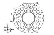
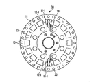
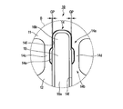
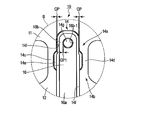
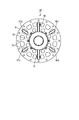
- FIG. 1 shows an example of a torque sensor 10 to which the present embodiment is applied.
- first strain sensor 19 and the second strain sensor 20 are disposed at positions symmetrical with respect to the centers of the first structure 11 and the second structure 12 (the center of torque action). In other words, the first strain sensor 19 and the second strain sensor 20 are arranged on the diameters of the annular first structure body 11 and second structure body 12.
- the stoppers 16 and 17 protect the mechanical deformation of the first strain sensor 19 and the second strain sensor 20 and have a function as a cover for the first strain sensor 19 and the second strain sensor 20. Details of the stoppers 16 and 17 will be described later.
- the strain generating bodies of the first strain sensor 19 and the second strain sensor 20 are used.
- strain is not concentrated on a plurality of strain gauges as sensor elements.
- the number of strain sensors may be three or more. In this case, the number of structures may be increased according to the number of strain sensors.
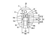
- the fourth structure 14 includes a first connection part 14 a and a second connection part 14 b as joint parts for joining the first strain sensor 19, and a third connection part 14 c and a fourth part as beams. It has the connection part 14d and the opening part 14e enclosed by the 1st connection part 14a, the 2nd connection part 14b, the 3rd connection part 14c, and the 4th connection part 14d.
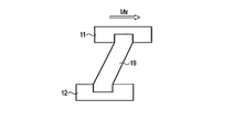
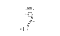
- FIG. 6A and 6B are diagrams schematically showing FIG. 5, FIG. 6A shows a case where a force in the torque (Mz) direction is applied to the torque sensor 10, and FIG. 6B shows a case other than torque on the torque sensor 10. The case where the force of the direction of (Fz, Mx) is applied is shown.
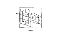
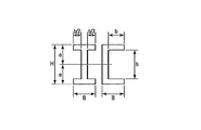
- FIG. 8A is a cross-sectional view along the line VIIIA-VIIIA shown in FIG. 7, and shows an example of the dimension of the high-rigidity portion HS1.
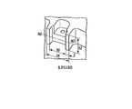
- FIG. 8B is a cross-sectional view taken along the line VIIIB-VIIIB shown in FIG. 7, and shows an example of dimensions of the low-rigidity portions LS1 and LS2.
- one end of the first strain sensor 19 and the second strain sensor 20 is connected to the protrusion 11-1 provided on the first structure 11, and the other end is connected to the second structure 12.
- Each is connected to the provided protrusion 12-1.
- the protrusions 11-1 and 12-1 have a thickness equivalent to, for example, the first structure 11 and the second structure 12.
- the distance between the protrusion 11-1 and the protrusion 12-1 is equal to the length L1 of the third connection portion 14c and the fourth connection portion 14d shown in FIG.
- the torque sensor 30 as a comparative example, only the third structure 13 acts as a high-rigidity part with respect to forces in the torque direction and directions other than torque, and the first strain sensor 19 and the second strain sensor 20 are the first Only the strain body is provided between the structure 11 and the second structure 12. For this reason, the first strain sensor 19 and the second strain are applied to the torque sensor 30 in either direction when a force in the torque (Mz) direction is applied or when a force in a direction other than the torque (Fz, Mx) is applied. The strain is concentrated on the strain gauge provided on the strain body of the strain sensor 20.
- the distortion with respect to the force in the torque (Mz) direction is larger than in the comparative example, and other than the torque (Fx, Fy, Fz, Mx, My ) Is less strained than the comparative example.
- the strain with respect to forces in the Fz and Mx directions can be significantly reduced compared to the comparative example. Therefore, according to the first embodiment, the first strain sensor 19 and the second strain sensor 20 can be reduced in distortion due to a force in a direction other than the torque, and the detection accuracy of the first strain sensor 19 and the second strain sensor 20 can be reduced. It is possible to prevent the decrease.
- FIG. 12 shows a second embodiment.
- the first strain sensor 19 is provided in the fourth structure 14, and the second strain sensor 20 is provided in the fifth structure 15. Since the first strain sensor 19 and the second strain sensor 20 have the same configuration, only the configuration of the first strain sensor 19 will be described.
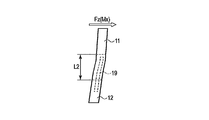
- the strain body 41 is made of a rectangular metal plate, for example, stainless steel (SUS).
- the thickness of the strain body 41 is thinner than the thickness of the third structure 13.
- the strain gauges 51, 52, 53, 54 are constituted by, for example, Cr—N thin film resistors provided on the strain generating body 41.
- the material of the thin film resistor is not limited to Cr—N.
- the effective length of the strain body 41 corresponds to the length between the location connected to the first connection portion 14a and the location connected to the second connection portion 14b.
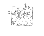
- the plurality of strain gauges 51, 52, 53, 54 are arranged in the region AR 1 on the second structure 12 side from the central portion CT of the effective length of the strain body 41 in the strain body 41.
- This region AR1 is a region where a large strain is generated in the strain generating body 41 within the range of the opening 14e.
- this area AR1 is an area where the sensitivity of the first strain sensor 19 with respect to forces in directions other than torque, for example, Fx and My directions, and the sensitivity of the first strain sensor 19 in the torque (Mz) direction are the same. It is.
- the strain gauges 51, 52, 53, 54 are arranged along the two diagonal lines DG1, DG2 of the strain body 41 in the longitudinal direction of the strain gauges 51, 52, 53, 54 in the area AR1. That is, the strain gauges 51 and 52 are arranged along one diagonal line DG1 whose longitudinal direction is indicated by a broken line, and the strain gauges 53 and 54 are arranged along the other diagonal line DG2 whose longitudinal direction is indicated by a broken line. .
- the diagonal lines DG1 and DG2 correspond to rectangular regions located in the opening 14e of the strain generating body 41.
- the strain gauges 51, 52, 53, and 54 of the first strain sensor 19 constitute one bridge circuit, and the strain gauges 51, 52, 53, and 54 of the second strain sensor 20 also constitute one bridge circuit. For this reason, the torque sensor 10 includes two bridge circuits.
- FIG. 13 shows an example of the bridge circuit 50 of the first strain sensor 19.
- the second strain sensor 20 also includes a bridge circuit having the same configuration as the bridge circuit 50.
- Each of the output voltage of the bridge circuit 50 of the first strain sensor 19 and the output voltage of the bridge circuit 50 of the second strain sensor 19 is compensated for offset, temperature, and the like using software (not shown), for example. Thereafter, the output voltage of the bridge circuit 50 of the first strain sensor 19 and the output voltage of the bridge circuit 50 of the second strain sensor 19 are integrated and output as a detection voltage of the torque sensor 10. Compensation for offset, temperature, etc. is not limited to software, but can also be performed by hardware.
- a series circuit of a strain gauge 52 and a strain gauge 53 and a series circuit of a strain gauge 54 and a strain gauge 51 are arranged between the power supply Vo and the ground GND.
- the output voltage Vout + is output from the connection node between the strain gauge 52 and the strain gauge 53
- the output voltage Vout ⁇ is output from the connection node between the strain gauge 54 and the strain gauge 51.
- the output voltage Vout + and the output voltage Vout ⁇ are supplied to the operational amplifier OP, and the output voltage Vout is output from the output terminal of the operational amplifier OP.
- the difference between the detection sensitivity of torque (Mz) and the detection sensitivity of other than torque (Fx, My) is as small as less than 1%.
- the difference between the detection sensitivity of torque and the detection sensitivity other than torque is several percent. Therefore, it is preferable to arrange a plurality of strain gauges 51, 52, 53, 54 in the area AR1 on the second structure 12 side.
- the bridge circuit 50 arranged in the region AR1 of the strain generating body 41 has a small difference in detection sensitivity with respect to the force in the torque direction and the force in the direction other than the torque, the first strain sensor 19 and the second strain sensor 20 The output voltage error is also small. For this reason, when the voltages output from the two bridge circuits 50 are calibrated, the detection errors other than the torque can be calibrated only by calibrating the detection error with respect to the torque. Therefore, since it is not necessary to provide another strain sensor to detect a force in a direction other than torque (Fx, My), the calibration time can be shortened and a high-speed response can be realized.
- the second embodiment is not limited to the structure of the torque sensor 10, and the strain gauges 51, 52, 53, and 54 may be disposed in the area AR1. For this reason, even if the arrangement according to the second embodiment is applied to a torque sensor 30 having a structure as shown in FIG. 9, for example, the same effect as that of the second embodiment can be obtained.
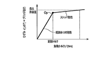
- FIG. 18 is a diagram for explaining the relationship between the torque as a load applied to the torque sensor 10 and the operation of the stopper 16.
- the output voltage is schematically shown.
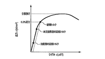
- the strain gauge is designed with a safety factor against impact and fatigue set to about 3 to 5.
- the safety factor is 3, the strain gauge stress is set to 1/3 of the 0.2% proof stress.
- the rated torque is also set to 1/3 of the breaking torque.
- the same effect as that of the third embodiment can be obtained by the first modification. Moreover, according to the first modification, it is possible to further protect the first strain sensor 19 (second strain sensor 20) by the protrusion 14g contacting the opening 16b-1 of the stopper 16. .
- the present invention is not limited to the above-described embodiments as they are, and can be embodied by modifying constituent elements without departing from the scope of the invention in the implementation stage.
- various inventions can be formed by appropriately combining a plurality of constituent elements disclosed in the above embodiments. For example, some components may be deleted from all the components shown in the embodiment. Furthermore, constituent elements over different embodiments may be appropriately combined.
- SYMBOLS 10 Torque sensor, 11 ... 1st structure, 12 ... 2nd structure, 13 ... 3rd structure, 14 ... 4th structure, 14a ... 1st connection part, 14b ... 2nd connection part, 14c ... 1st 3 connection part, 14d ... 4th connection part, 14e ... opening part, 14f ... recessed part (engagement part), 14g ... projection, 15 ... 5th structure, 16, 16-1, 16-2 ... stopper, 16b- DESCRIPTION OF SYMBOLS 1 ... Opening part, 17, 17-1, 17-2 ... Stopper, 19 ... 1st strain sensor, 20 ... 2nd strain sensor, 41 ... Strain body, GP, GP1 ... Gap, 51, 52, 53, 54 ... Strain gauge as a sensor element.
Landscapes
- Physics & Mathematics (AREA)
- General Physics & Mathematics (AREA)
- Engineering & Computer Science (AREA)
- Microelectronics & Electronic Packaging (AREA)
- Power Engineering (AREA)
- Mechanical Engineering (AREA)
- Robotics (AREA)
- Condensed Matter Physics & Semiconductors (AREA)
- Computer Hardware Design (AREA)
- Ceramic Engineering (AREA)
- Force Measurement Appropriate To Specific Purposes (AREA)
- Manipulator (AREA)
- Pressure Sensors (AREA)
- Power Steering Mechanism (AREA)
Priority Applications (3)
| Application Number | Priority Date | Filing Date | Title |
|---|---|---|---|
| CN201980011559.5A CN111684251B (zh) | 2018-03-29 | 2019-02-08 | 扭矩传感器 |
| EP19777981.2A EP3779389A4 (en) | 2018-03-29 | 2019-02-08 | TORQUE SENSOR |
| US16/934,476 US11499879B2 (en) | 2018-03-29 | 2020-07-21 | Torque sensor having a strain sensor |
Applications Claiming Priority (2)
| Application Number | Priority Date | Filing Date | Title |
|---|---|---|---|
| JP2018063827A JP6976892B2 (ja) | 2018-03-29 | 2018-03-29 | トルクセンサ |
| JP2018-063827 | 2018-03-29 |
Related Child Applications (1)
| Application Number | Title | Priority Date | Filing Date |
|---|---|---|---|
| US16/934,476 Continuation US11499879B2 (en) | 2018-03-29 | 2020-07-21 | Torque sensor having a strain sensor |
Publications (1)
| Publication Number | Publication Date |
|---|---|
| WO2019187705A1 true WO2019187705A1 (ja) | 2019-10-03 |
Family
ID=68058903
Family Applications (1)
| Application Number | Title | Priority Date | Filing Date |
|---|---|---|---|
| PCT/JP2019/004751 WO2019187705A1 (ja) | 2018-03-29 | 2019-02-08 | トルクセンサ |
Country Status (6)
| Country | Link |
|---|---|
| US (1) | US11499879B2 (zh) |
| EP (1) | EP3779389A4 (zh) |
| JP (1) | JP6976892B2 (zh) |
| CN (1) | CN111684251B (zh) |
| TW (2) | TWI787457B (zh) |
| WO (1) | WO2019187705A1 (zh) |
Families Citing this family (4)
| Publication number | Priority date | Publication date | Assignee | Title |
|---|---|---|---|---|
| JP6808469B2 (ja) * | 2016-12-07 | 2021-01-06 | 日本電産コパル電子株式会社 | トルクセンサ |
| JP1667823S (zh) * | 2019-11-29 | 2020-09-07 | ||
| JP1667822S (zh) * | 2019-11-29 | 2020-09-07 | ||
| CN112611489A (zh) * | 2020-12-21 | 2021-04-06 | 陕西电器研究所 | 一种基于薄膜溅射的抗过载扭矩传感器 |
Citations (6)
| Publication number | Priority date | Publication date | Assignee | Title |
|---|---|---|---|---|
| JP2007040774A (ja) * | 2005-08-02 | 2007-02-15 | Ono Sokki Co Ltd | トルク計 |
| EP2322905A1 (de) * | 2009-11-16 | 2011-05-18 | Baumer Innotec AG | Kraftmesszelle zur Messung der Einspritzkraft beim Spritzgiessen |
| JP2013096735A (ja) | 2011-10-28 | 2013-05-20 | Toyota Motor Corp | 起歪体及びトルクセンサ |
| JP2015028430A (ja) * | 2013-07-30 | 2015-02-12 | 日産自動車株式会社 | トルク検出装置 |
| JP2015049209A (ja) | 2013-09-04 | 2015-03-16 | トヨタ自動車株式会社 | トルクセンサ |
| JP2017172983A (ja) | 2016-03-18 | 2017-09-28 | 株式会社安川電機 | ロボット及びトルクセンサ |
Family Cites Families (58)
| Publication number | Priority date | Publication date | Assignee | Title |
|---|---|---|---|---|
| US4640138A (en) * | 1985-03-06 | 1987-02-03 | Mts Systems Corporation | Multiple axis load sensitive transducer |
| DE4133418C2 (de) * | 1991-10-09 | 1993-11-04 | Daimler Benz Ag | Mehrkomponenten-messscheibenrad |
| DE4208522C2 (de) * | 1992-03-18 | 2000-08-10 | Hottinger Messtechnik Baldwin | Drehmomentsensor |
| CN2165435Y (zh) * | 1993-09-08 | 1994-05-18 | 中国科学院合肥智能机械研究所 | 六自由度力和力矩传感器 |
| CN2221208Y (zh) * | 1993-12-20 | 1996-02-28 | 合肥东华机电自动化研究所 | 多分量力和力矩传感器 |
| US5672834A (en) * | 1994-01-29 | 1997-09-30 | British Autogard Limited | Torgue indicating device |
| DE19627385A1 (de) * | 1996-07-06 | 1998-01-08 | Bayerische Motoren Werke Ag | Radmeßnabe |
| US6038933A (en) * | 1997-07-15 | 2000-03-21 | Mts Systems Corporation | Multi-axis load cell |
| US6418797B1 (en) * | 1998-03-04 | 2002-07-16 | Graber Products, Inc. | Apparatus and method for sensing power in a bicycle |
| WO2000026625A1 (en) * | 1998-10-30 | 2000-05-11 | Lambson Vernon A | Method and apparatus for measuring torque |
| JP2002202212A (ja) * | 2000-11-16 | 2002-07-19 | Alpha Technologies | 低トルクトランスデューサ及びそれを用いたトルク測定装置 |
| DE10144143C1 (de) * | 2001-09-10 | 2002-08-14 | Kostal Leopold Gmbh & Co Kg | Torsionsmodul für eine Drehmomenterfassungseinrichtung |
| DE50302070D1 (de) * | 2002-04-12 | 2006-02-02 | Deutsch Zentr Luft & Raumfahrt | Verfahren und Einrichtung zum Messen des Abtriebsdrehmoments eines Elektromotors mit einem diesem nachgeordneten Getriebe |
| US6871552B2 (en) * | 2002-04-12 | 2005-03-29 | Deutsches Zentrum für Luft- und Raumfahrt e.V. | Force moment sensor |
| DE20209850U1 (de) * | 2002-06-25 | 2002-09-19 | Wille Gmbh & Co | Drehmomentsensor mit Stegen |
| JP4303091B2 (ja) * | 2003-11-10 | 2009-07-29 | ニッタ株式会社 | 歪みゲージ型センサおよびこれを利用した歪みゲージ型センサユニット |
| US20080204266A1 (en) * | 2004-02-03 | 2008-08-28 | Jussi Malmberg | Method and Device For Implementing Vibration Output Commands in Mobile Terminal Devices |
| WO2005075950A1 (ja) * | 2004-02-04 | 2005-08-18 | Ono Sokki Co.,Ltd. | トルク計 |
| JP4764619B2 (ja) * | 2004-08-23 | 2011-09-07 | 株式会社エー・アンド・デイ | 回転型分力計測装置 |
| JP2011149696A (ja) * | 2008-05-09 | 2011-08-04 | Kokusai Keisokki Kk | 衝撃試験装置 |
| US7743672B2 (en) * | 2008-06-06 | 2010-06-29 | Kulite Semiconductor Products, Inc. | Multiple axis load cell controller |
| KR101135426B1 (ko) * | 2009-11-26 | 2012-04-20 | 한국생산기술연구원 | 사다리꼴 형상의 스포크를 구비한 1축 토크센서 |
| DE202010005613U1 (de) | 2010-06-10 | 2010-09-02 | Eduard Wille Gmbh & Co. Kg | Drehmoment-Aufnehmer mit U-Profil-Steg |
| JP4948630B2 (ja) * | 2010-08-05 | 2012-06-06 | 株式会社トライフォース・マネジメント | トルクセンサ |
| EP2420803A1 (de) * | 2010-08-13 | 2012-02-22 | BALLUFF GmbH | Vorrichtung zum Erfassen des Verdrehwinkels einer Welle und /oder eines an der Welle auftretenden Drehmoments und Verfahren zum Betreiben der Vorrichtung |
| JP5963453B2 (ja) * | 2011-03-15 | 2016-08-03 | 株式会社荏原製作所 | 検査装置 |
| JP5640905B2 (ja) * | 2011-06-14 | 2014-12-17 | トヨタ自動車株式会社 | 起歪体及びこれを含む装置 |
| JP2013044684A (ja) * | 2011-08-25 | 2013-03-04 | Seiko Epson Corp | ハンドラー、及び部品検査装置 |
| CN102494819A (zh) * | 2011-11-29 | 2012-06-13 | 北京邮电大学 | 一种基于弹性梁的关节扭矩传感器 |
| EP2631624A3 (de) * | 2012-02-27 | 2014-06-18 | Deutsches Zentrum für Luft- und Raumfahrt e.V. | Kraft-Momenten-Sensor zum Messen von Kräften und Momenten |
| US8776615B2 (en) * | 2012-05-01 | 2014-07-15 | Honeywell International Inc. | Three-axis low profile load cell and sensing beam |
| KR101335432B1 (ko) * | 2012-05-10 | 2013-11-29 | 전자부품연구원 | 힘토크 센서, 힘토크 센서 프레임 및 힘토크 측정 방법 |
| CN102840944B (zh) * | 2012-08-08 | 2015-01-07 | 燕山大学 | 一种近奇异构型的大量程并联六维力传感器 |
| CN202928733U (zh) * | 2012-09-24 | 2013-05-08 | 江苏大学 | 一种分体式倾斜辐条轮辐扭矩传感器 |
| WO2014110682A1 (en) * | 2013-01-18 | 2014-07-24 | Robotiq Inc. | Force/torque sensor, apparatus and method for robot teaching and operation |
| GB2511101B (en) * | 2013-02-22 | 2017-05-10 | Transense Tech Plc | Torque measurement flexplates |
| US8984963B2 (en) * | 2013-03-15 | 2015-03-24 | H. Aaron Christmann | Rotatable torque-measuring apparatus and method |
| DE102014210379B4 (de) * | 2014-06-02 | 2016-03-24 | Kuka Roboter Gmbh | Drehmomentsensor und Verfahren zum Erfassen von an oder in einem Gelenk eines Gelenkarmroboters auftretenden Drehmomenten |
| DE102015110353A1 (de) * | 2015-06-26 | 2016-12-29 | Dr. Fritz Faulhaber Gmbh & Co. Kg | Getriebe für Klein- und Kleinstantrieb mit Drehmomentmessglied |
| DE102015214170A1 (de) * | 2015-07-27 | 2017-02-02 | Kuka Roboter Gmbh | Roboter mit einer Kraftmesseinrichtung |
| CN105784219B (zh) * | 2015-12-17 | 2018-08-28 | 北京希卓信息技术有限公司 | 一种扭矩传感器及其测试系统 |
| JP6752576B2 (ja) * | 2016-01-13 | 2020-09-09 | キヤノン株式会社 | 駆動機構、ロボット装置、駆動機構の制御方法、ロボット装置の制御方法、物品の製造方法、制御プログラム、記録媒体、及び支持部材 |
| CN106153237A (zh) * | 2016-06-14 | 2016-11-23 | 南京神源生智能科技有限公司 | 一种小型六维力和力矩传感器 |
| DE102016010552B3 (de) * | 2016-08-31 | 2017-11-09 | Sensodrive Gmbh | Drehmomentsensor mit Dichtungsmembran |
| DE102016010549A1 (de) * | 2016-08-31 | 2018-03-01 | Sensodrive Gmbh | Drehmomentsensor mit Nebenschlussspeiche |
| DE102016010551B3 (de) * | 2016-08-31 | 2018-02-08 | Sensodrive Gmbh | Drehmomentsensor mit radialelastischer Momentübertragung |
| DE102016012324A1 (de) * | 2016-10-17 | 2018-04-19 | Franka Emika Gmbh | Drehmomentsensorvorrichtung und Verfahren zum Erfassen von Drehmomenten |
| JP6808469B2 (ja) * | 2016-12-07 | 2021-01-06 | 日本電産コパル電子株式会社 | トルクセンサ |
| CN106706188A (zh) * | 2016-12-08 | 2017-05-24 | 陕西电器研究所 | 一种高刚度扭矩传感器 |
| US11187600B2 (en) * | 2016-12-27 | 2021-11-30 | Dai-Ichi Seiko Co., Ltd. | Torque sensor |
| JP6692762B2 (ja) * | 2017-02-13 | 2020-05-13 | 日本電産コパル電子株式会社 | トルクセンサ |
| CN206756350U (zh) * | 2017-03-15 | 2017-12-15 | 北京中航兴盛测控技术有限公司 | 薄膜应变式扭矩传感器 |
| CN206618526U (zh) * | 2017-03-15 | 2017-11-07 | 北京中航兴盛测控技术有限公司 | 高性能应变合金薄膜扭矩传感器 |
| CN113899480A (zh) * | 2017-08-25 | 2022-01-07 | 非夕机器人有限公司 | 用于测试扭矩的传感器 |
| CN107782482A (zh) * | 2017-11-17 | 2018-03-09 | 中国科学院宁波材料技术与工程研究所 | 多维力/力矩传感器 |
| TWI716789B (zh) * | 2018-12-20 | 2021-01-21 | 財團法人工業技術研究院 | 多軸力感測裝置 |
| JP1667823S (zh) * | 2019-11-29 | 2020-09-07 | ||
| JP1667822S (zh) * | 2019-11-29 | 2020-09-07 |
-
2018
- 2018-03-29 JP JP2018063827A patent/JP6976892B2/ja active Active
-
2019
- 2019-02-08 WO PCT/JP2019/004751 patent/WO2019187705A1/ja active Application Filing
- 2019-02-08 CN CN201980011559.5A patent/CN111684251B/zh active Active
- 2019-02-08 EP EP19777981.2A patent/EP3779389A4/en active Pending
- 2019-02-12 TW TW108104623A patent/TWI787457B/zh active
- 2019-02-12 TW TW112101291A patent/TWI829502B/zh active
-
2020
- 2020-07-21 US US16/934,476 patent/US11499879B2/en active Active
Patent Citations (6)
| Publication number | Priority date | Publication date | Assignee | Title |
|---|---|---|---|---|
| JP2007040774A (ja) * | 2005-08-02 | 2007-02-15 | Ono Sokki Co Ltd | トルク計 |
| EP2322905A1 (de) * | 2009-11-16 | 2011-05-18 | Baumer Innotec AG | Kraftmesszelle zur Messung der Einspritzkraft beim Spritzgiessen |
| JP2013096735A (ja) | 2011-10-28 | 2013-05-20 | Toyota Motor Corp | 起歪体及びトルクセンサ |
| JP2015028430A (ja) * | 2013-07-30 | 2015-02-12 | 日産自動車株式会社 | トルク検出装置 |
| JP2015049209A (ja) | 2013-09-04 | 2015-03-16 | トヨタ自動車株式会社 | トルクセンサ |
| JP2017172983A (ja) | 2016-03-18 | 2017-09-28 | 株式会社安川電機 | ロボット及びトルクセンサ |
Also Published As
| Publication number | Publication date |
|---|---|
| EP3779389A1 (en) | 2021-02-17 |
| TW202321664A (zh) | 2023-06-01 |
| TW201942549A (zh) | 2019-11-01 |
| CN111684251A (zh) | 2020-09-18 |
| TWI829502B (zh) | 2024-01-11 |
| JP6976892B2 (ja) | 2021-12-08 |
| US20200348194A1 (en) | 2020-11-05 |
| JP2019174325A (ja) | 2019-10-10 |
| EP3779389A4 (en) | 2021-12-22 |
| CN111684251B (zh) | 2021-12-24 |
| TWI787457B (zh) | 2022-12-21 |
| US11499879B2 (en) | 2022-11-15 |
Similar Documents
| Publication | Publication Date | Title |
|---|---|---|
| WO2019187705A1 (ja) | トルクセンサ | |
| US20190250051A1 (en) | Torque sensor | |
| WO2019187706A1 (ja) | トルクセンサ | |
| JP5243988B2 (ja) | 多軸力覚センサおよび加速度センサ | |
| JP6999586B2 (ja) | 弾性体とそれを用いた力覚センサ | |
| JP7034811B2 (ja) | 歪センサの固定装置とそれを用いたトルクセンサ | |
| WO2018105210A1 (ja) | トルクセンサ | |
| JP2019015591A (ja) | ひずみゲージ及び多軸力センサ | |
| WO2019187707A1 (ja) | トルクセンサ | |
| US11781928B2 (en) | Torque sensor attachment structure | |
| JP7062827B2 (ja) | トルクセンサ | |
| TWI818989B (zh) | 轉矩感測器 | |
| JP2019158419A (ja) | トルクセンサ | |
| JP2021063844A (ja) | トルクセンサ | |
| JP7091545B2 (ja) | トルクセンサ | |
| JP2023055670A (ja) | トルクセンサデバイス用感応膜およびトルクセンサデバイス |
Legal Events
| Date | Code | Title | Description |
|---|---|---|---|
| 121 | Ep: the epo has been informed by wipo that ep was designated in this application |
Ref document number: 19777981 Country of ref document: EP Kind code of ref document: A1 |
|
| NENP | Non-entry into the national phase |
Ref country code: DE |
|
| WWE | Wipo information: entry into national phase |
Ref document number: 2019777981 Country of ref document: EP |
|
| ENP | Entry into the national phase |
Ref document number: 2019777981 Country of ref document: EP Effective date: 20201029 |