WO2019187210A1 - Outil d'insertion - Google Patents
Outil d'insertion Download PDFInfo
- Publication number
- WO2019187210A1 WO2019187210A1 PCT/JP2018/033078 JP2018033078W WO2019187210A1 WO 2019187210 A1 WO2019187210 A1 WO 2019187210A1 JP 2018033078 W JP2018033078 W JP 2018033078W WO 2019187210 A1 WO2019187210 A1 WO 2019187210A1
- Authority
- WO
- WIPO (PCT)
- Prior art keywords
- longitudinal axis
- adhesive layer
- proximal end
- end side
- cylindrical member
- Prior art date
Links
Images


Classifications
-
- A—HUMAN NECESSITIES
- A61—MEDICAL OR VETERINARY SCIENCE; HYGIENE
- A61B—DIAGNOSIS; SURGERY; IDENTIFICATION
- A61B1/00—Instruments for performing medical examinations of the interior of cavities or tubes of the body by visual or photographical inspection, e.g. endoscopes; Illuminating arrangements therefor
- A61B1/00147—Holding or positioning arrangements
- A61B1/00154—Holding or positioning arrangements using guiding arrangements for insertion
-
- A—HUMAN NECESSITIES
- A61—MEDICAL OR VETERINARY SCIENCE; HYGIENE
- A61B—DIAGNOSIS; SURGERY; IDENTIFICATION
- A61B1/00—Instruments for performing medical examinations of the interior of cavities or tubes of the body by visual or photographical inspection, e.g. endoscopes; Illuminating arrangements therefor
- A61B1/00112—Connection or coupling means
- A61B1/00121—Connectors, fasteners and adapters, e.g. on the endoscope handle
- A61B1/00128—Connectors, fasteners and adapters, e.g. on the endoscope handle mechanical, e.g. for tubes or pipes
-
- A—HUMAN NECESSITIES
- A61—MEDICAL OR VETERINARY SCIENCE; HYGIENE
- A61B—DIAGNOSIS; SURGERY; IDENTIFICATION
- A61B1/00—Instruments for performing medical examinations of the interior of cavities or tubes of the body by visual or photographical inspection, e.g. endoscopes; Illuminating arrangements therefor
- A61B1/00147—Holding or positioning arrangements
- A61B1/0016—Holding or positioning arrangements using motor drive units
-
- G—PHYSICS
- G02—OPTICS
- G02B—OPTICAL ELEMENTS, SYSTEMS OR APPARATUS
- G02B23/00—Telescopes, e.g. binoculars; Periscopes; Instruments for viewing the inside of hollow bodies; Viewfinders; Optical aiming or sighting devices
- G02B23/24—Instruments or systems for viewing the inside of hollow bodies, e.g. fibrescopes
-
- A—HUMAN NECESSITIES
- A61—MEDICAL OR VETERINARY SCIENCE; HYGIENE
- A61M—DEVICES FOR INTRODUCING MEDIA INTO, OR ONTO, THE BODY; DEVICES FOR TRANSDUCING BODY MEDIA OR FOR TAKING MEDIA FROM THE BODY; DEVICES FOR PRODUCING OR ENDING SLEEP OR STUPOR
- A61M25/00—Catheters; Hollow probes
- A61M25/01—Introducing, guiding, advancing, emplacing or holding catheters
- A61M25/0105—Steering means as part of the catheter or advancing means; Markers for positioning
- A61M25/0113—Mechanical advancing means, e.g. catheter dispensers
Definitions
- This invention relates to the insertion tool provided with the cylindrical member arrange
- an insertion tool including an insertion portion that is inserted into the subject is used in, for example, the medical field or the industrial field.
- the insertion tool includes, for example, an endoscope as disclosed in International Publication No. WO2017 / 006598.
- An endoscope disclosed in International Publication No. WO2017 / 006598 has a configuration in which a cylindrical member that rotates on the outer periphery of an insertion portion is rotated.
- the endoscope disclosed in International Publication No. WO2017 / 006598 has a flange portion protruding from the insertion portion for maintaining the position of the cylindrical member with respect to the insertion portion.
- a taper surface is provided on the flange portion to prevent a radial step from occurring in the insertion portion.
- An object of the present invention is to solve the above-described points, and in an insertion tool including a cylindrical member disposed on the outer periphery of an insertion portion, it is possible to smoothly move the insertion portion in a subject. To do.
- An insertion tool includes an insertion portion that extends along a longitudinal axis, and a cylindrical shape that extends along the longitudinal axis in the insertion portion, and a driving force is transmitted around the longitudinal axis.
- a cylindrical member that rotates in the longitudinal direction a flange portion that holds the position of the cylindrical member on the outer periphery of the insertion portion in the longitudinal axis direction, and a proximal end side along the longitudinal axis direction of the flange portion,
- a taper portion having an outer diameter that decreases toward the base end side, and an adhesive layer formed so as to smoothly connect the base end portion of the taper portion and the outer periphery of the insertion portion.
- the insertion portion 2 has an elongated insertion portion 2 that can be introduced into a subject such as a human body, and the insertion portion 2 has a configuration for observing the inside of the subject.
- the subject into which the insertion portion 2 of the endoscope 1 is introduced is not limited to a human body, and may be another living body or an artificial object such as a machine or a building.
- the insertion tool is not limited to an endoscope, and may be a treatment tool that performs excision or suction in a subject.
- the endoscope 1 is a medical endoscope.
- the endoscope 1 includes an insertion portion 2 that extends along the longitudinal axis, an operation portion 3 that is located at a proximal end that is one end of the insertion portion 2, and a universal cord 4 that extends from the operation portion 3.
- positioned on the outer periphery of the insertion part 2 is included.
- the insertion portion 2 is configured by sequentially connecting a distal end portion 2a, a bending portion 2b, a first flexible tube portion 2c, a power transmission portion 10, and a second flexible tube portion 2d from the distal end to the proximal end. Yes.
- the configuration for observing the inside of the subject is disposed at the tip 2a.
- the distal end portion 2a is provided with an imaging device that includes an objective lens and an imaging device for optically observing the inside of the subject.
- the tip portion 2a is also provided with an illumination light emitting unit that emits light that illuminates the subject of the imaging apparatus.
- an ultrasonic transducer for observing the inside of the subject acoustically using ultrasonic waves may be disposed at the distal end portion 2a.
- the bending portion 2 b is bent according to the rotation of the operation knob 6 provided in the operation portion 3. Since the configuration of the distal end portion 2a and the bending portion 2b is the same as that of a known endoscope, detailed description thereof is omitted.
- the first flexible tube portion 2c and the second flexible tube portion 2d have flexibility and bend according to the applied external force.
- the power transmission unit 10 connecting the first flexible tube portion 2c and the second flexible tube portion 2d is rigid and does not bend.
- the power transmission unit 10 is coupled to a cylindrical member 50 disposed on the outer periphery of the first flexible tube 2c.
- the power transmission unit 10 transmits the power generated by the actuator 8 such as an electric motor included in the endoscope 1 to the cylindrical member 50.
- the actuator 8 can switch the presence or absence of power generation according to the operation of a switch (not shown).
- the drive shaft 8a is inserted through the operation unit 3 and the second flexible tube unit 2c.
- the drive shaft 8a has flexibility, and rotates around the longitudinal axis by the power generated by the actuator 8.
- the drive shaft 8 a transmits the power generated by the actuator 8 to the power transmission unit 10.
- the cylindrical member 50 rotates around the longitudinal axis of the insertion portion 2 with respect to the first flexible tube portion 2c by the power generated by the actuator 8.
- the configuration of the power transmission unit 10 will be described later.
- An endoscope connector 5 configured to be connectable to an external device (not shown) is provided at the base end of the universal cord 4.
- the external device to which the endoscope connector 5 is connected includes a camera control unit for controlling the imaging device provided at the distal end portion 2a.
- FIG. 2 is an external view of the tubular member 50 and the power transmission unit 10 with the tubular member 50 removed.
- a dashed line in FIG. 2 is the longitudinal axis L of the insertion portion 2.
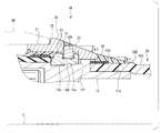
- FIG. 3 is a partial cross-sectional view of the power transmission unit 10.
- FIG. 3 shows a cross section of a portion surrounded by a broken-line square in FIG. 2 by a plane parallel to the longitudinal axis L. 2 and 3, the left side in the drawing along the longitudinal axis L is the distal end side, and the right side is the proximal end side.
- the power transmission unit 10 includes a main body frame 11, a rotating ring 12, a covering member 13, a stationary ring 20, and an adhesive layer 30.
- the main body frame 11 is a cylindrical member that connects the proximal end of the first flexible tube portion 2c and the distal end of the second flexible tube portion 2d. That is, the main body frame 11 is fixed to the insertion portion 2.
- the rotating ring 12, the covering member 13, the stationary ring 20, and the adhesive layer 30 are disposed.
- the main body frame 11 is a hard member made of a material having a predetermined rigidity such as metal, resin, or ceramic. Although the main body frame 11 is shown as a single member in FIG. 3, the main body frame 11 may be divided into a plurality of members.
- the main body frame 11 is formed with an opening 11a that opens toward the radially outer side of the insertion portion 2.
- the radially outer side of the insertion portion 2 is a direction from the inner side to the outer side of the insertion portion 2 along an axis orthogonal to the longitudinal axis L.
- a drive gear 11b is disposed in the opening 11a.
- the drive gear 11b is an external gear.
- the drive gear 11b is supported by the main body frame 11 so as to be rotatable around an axis parallel to the longitudinal axis L. A part of the tooth surface of the drive gear 11b is exposed to the outside of the main body frame 11 through the opening 11a.
- the rotation shaft of the drive gear 11b is connected to the tip of the drive shaft 8a inserted through the second flexible tube portion 2d.
- the base end of the drive shaft 8 a is connected to the actuator 8.
- the drive shaft 8a transmits the power generated by the actuator 8 to the drive gear 11b. That is, when the actuator 8 generates power, the drive gear 11b rotates.
- the base end of the main body frame 11 is provided with a cylindrical coupling portion 11c.
- the coupling portion 11c is a portion where the outer skin 2d1 of the second flexible tube portion 2d is fitted.
- the outer skin 2d1 is a tubular member mainly made of resin and having flexibility.
- the outer skin 2d1 constitutes the outer surface of the second flexible tube portion 2d.
- the outer skin 2d1 is shown as a single member, but the outer skin 2d1 may be configured by stacking a plurality of members in the thickness direction. Further, the outer peripheral surface of the outer skin 2d1 may be subjected to a surface treatment such as a coating containing fluorine.
- the coupling portion 11c is press-fitted from the opening at the tip of the outer skin 2d1 so as to push the opening.
- the adhesive agent which improves the coupling strength and watertightness between both may be arrange
- a bobbin winding portion 11d is provided on the outer peripheral surface of the portion where the coupling portion 11c of the outer skin 2d1 is press-fitted.
- the thread winding portion 11d is a portion where the yarn is wound a plurality of times so as to tighten the portion where the joint portion 11c of the outer skin 2d1 is press-fitted.
- the bobbin winding part 11d improves the joint strength and water tightness between the joint part 11c and the outer skin 2d1.
- the rotary ring 12 is an annular member that is disposed on the outer periphery of the main body frame 11 and rotates around the longitudinal axis L with respect to the main body frame 11.
- a driven gear 12a that meshes with the drive gear 11b is provided on the inner periphery of the rotary ring 12.
- the driven gear 12a is an internal gear. That is, the rotating ring 12 rotates around the longitudinal axis L according to the rotation of the drive gear 11b.
- the rotating ring 12 is provided with a plurality of rollers 12b.
- Each roller 12 b is supported so as to be rotatable about an axis parallel to the longitudinal axis L with respect to the rotating ring 12.
- the rotation axes of the plurality of rollers 12b are arranged at a predetermined interval on the same circle around the longitudinal axis L in a plane orthogonal to the longitudinal axis L. As shown in FIG. 3, the roller 12 b protrudes radially outward from the outer periphery of the main body frame 11.
- the covering member 13 is a tubular film that covers the outer periphery of the main body frame 11 and the rotating ring 12.
- the covering member 13 is made of an elastically deformable material such as rubber.
- the covering member 13 constitutes a part of the outer surface of the power transmission unit 10.
- the covering member 13 prevents liquid, foreign matter, and the like from entering the insertion portion 2 through the opening 11a of the main body frame 11.
- the covering member 13 is fixed to the main body frame 11. Therefore, the rotating ring 12 rotates while being in contact with the inner peripheral surface of the covering member 13 inside the covering member 13.
- the covering member 13 Since the covering member 13 is a film that is elastically deformed, as shown in FIG. 2, it protrudes radially outward on the outer surface of the power transmission unit 10 at a location where the roller 12 b is in contact with the inner side of the covering member 13.
- An engaging projection 10a is formed. The position of the engaging protrusion 10 a moves around the longitudinal axis L along with the rotating ring 12.
- the fixed ring 20 is an annular member fixed to the outer periphery of the main body frame 11.
- the stationary ring 20 is disposed on the proximal end side with respect to the engagement protrusion 10a. As shown in FIG. 5, the stationary ring 20 has a through-hole 20 a that can be inserted through a portion on the base end side of the main body frame 11.
- the stationary ring 20 is a hard member made of a material having a predetermined rigidity such as metal, resin, ceramic, or the like.
- the stationary ring 20 is configured such that a sliding portion 21, a flange portion 22, and a tapered portion 23 are sequentially connected from the distal end side toward the proximal end side.
- the stationary ring 20 is composed of a single member.
- the sliding portion 21 is a cylindrical portion with the longitudinal axis L as the center.
- the outer diameter of the sliding portion 21 is substantially the same as or larger than the circle circumscribing the plurality of engaging protrusions 10a.
- a connector portion 52 (described later) of the tubular member 50 is in sliding contact with the outer periphery of the sliding portion 21.
- the flange portion 22 is a portion protruding outward from the sliding portion 21.
- the outer peripheral shape of the flange portion 22 is a cylindrical shape with the longitudinal axis L as the center. That is, the outer diameter of the flange portion 22 is larger than that of the sliding portion 21. Further, the outer diameter of the flange portion 22 is larger than the outer diameter of the second flexible tube portion 2d.
- the flange portion 22 holds the position in the direction along the longitudinal axis L with respect to the insertion portion 2 of the tubular member 50 by contacting the proximal end of the tubular member 50.
- the taper portion 23 is a conical portion with the longitudinal axis L as the center.
- the outer diameter of the taper portion 23 decreases toward the proximal end side along the longitudinal axis L.
- the outer diameter of the tip of the taper portion 23 is the same as that of the flange portion 22.
- the outer diameter of the proximal end of the tapered portion 23 is smaller than the outer diameter of the distal end, but larger than the outer diameter of the second flexible tube portion 2d.
- the flange portion 22 is a portion having the largest outer diameter in the insertion portion 2 with the tubular member 50 removed.
- the taper portion 23 eliminates a step caused by a difference in outer diameter between the flange portion 22 and the second flexible tube portion 2d located on the proximal end side of the flange portion 22.
- the step refers to a sudden change in the outer diameter of the insertion portion 2 in the direction along the longitudinal axis L.
- a part of the base end side of the taper portion 23 overlaps the outside of the coupling portion 11c. That is, the distal end of the outer skin 2 d 1 that covers the outer periphery of the coupling portion 11 c is located on the distal end side with respect to the proximal end portion of the tapered portion 23. Therefore, in this embodiment, the base end part of the taper part 23 is located in the radial direction outer side with respect to the outer peripheral surface of the outer skin 2d1, and between the base end part of the taper part 23 and the outer peripheral surface of the outer skin 2d1. There is still a step.
- the adhesive layer 30 is formed so as to smoothly connect the proximal end portion of the tapered portion 23 and the outer peripheral surface of the outer skin 2d1.
- the adhesive layer 30 fills a step between the proximal end portion of the tapered portion 23 and the outer peripheral surface of the outer skin 2d1, and has a conical outer shape whose outer diameter decreases toward the proximal end side.
- the adhesive layer 30 is formed so as to cover the bobbin 11d in addition to the outer periphery of the outer skin 2d1.
- the adhesion strength of the adhesive layer 30 to the bobbin winding portion 11d is lower than the adhesion strength of the adhesive layer 30 to the outer periphery of the outer skin 2d1. For this reason, when the power transmission unit 10 is disassembled during maintenance of the endoscope 1 or the like, the work of peeling the adhesive layer 30 is facilitated.
- FIG. 4 is an enlarged view showing the tapered portion 23 and the adhesive layer 30 in FIG.
- the angle ⁇ 1 with respect to the longitudinal axis L of the outer surface of the adhesive layer 30 is smaller than the angle ⁇ 2 with respect to the longitudinal axis L of the conical surface of the tapered portion 23. That is, the amount of change in the outer diameter per predetermined distance in the direction along the longitudinal axis L in the adhesive layer 30 is smaller than the amount of change in the outer diameter per predetermined distance in the direction along the longitudinal axis L in the tapered portion 23. .
- the power transmission portion 10 is moved when the insertion portion 2 is moved in the proximal direction within the subject. It is possible to make it difficult to get caught in a narrowed portion or a convex portion in the specimen.
- the convex portion 2d2 serving as an index for applying the adhesive layer 30 so as to have the aforementioned conical shape when the endoscope 1 is assembled is formed on the outer periphery of the outer skin 2d1.
- the convex portion 2d2 is provided at a predetermined distance along the longitudinal axis L from the tip of the outer skin 2d1.
- the convex part 2d2 is formed in the whole circumferential direction of the outer periphery of the outer skin 2d1.
- the convex portion 2 d 2 indicates the position of the proximal end of the adhesive layer 30.
- the formation method of the convex part 2d2 is not specifically limited.
- the convex portion 2d2 can be formed by cutting a coating formed on the outer periphery of the outer skin 2d1.
- the base end of the adhesive layer 30 is arranged on the front end side with respect to the base end of the coupling portion 11c press-fitted into the outer skin 2d1. That is, the hard coupling portion 11c is press-fitted inside the portion covered with the adhesive layer 30 of the outer skin 2d1.
- the adhesive layer 30 is disposed so as to cover only the non-curved region of the outer skin 2d1. According to this embodiment, since the contact surface between the adhesive layer 30 and the outer skin 2d1 is not deformed when the endoscope 1 is used, a gap is generated between the adhesive layer 30 and the outer skin 2d1. Can be prevented.
- the base end of the tapered portion 23 has a rounded R shape.
- the cylindrical member 50 has a cylindrical shape in which a through hole 50 a through which the first flexible tube portion 2 c can be inserted is formed.
- the cylindrical member 50 is configured such that a deformable portion 51 that is provided on the distal end side and has flexibility, and a rigid connector portion 52 that is provided on the proximal end side are connected in a direction along the longitudinal axis L.
- the deformable portion 51 Since the deformable portion 51 has flexibility, it bends together with the first flexible tube portion 2c inserted through the through hole 50a. Fins 51 a are provided on the outer periphery of the deformable portion 51.
- the fin 51a has a spiral shape with the longitudinal axis L as the central axis. That is, the fin 13b has a shape corresponding to the threaded portion of the male screw.
- the connector part 52 is a cylindrical part that is in sliding contact with the outer periphery of the sliding part 21 of the power transmission part 10.
- the inner diameter of the connector part 52 is larger than the outer diameter of the sliding part 21 and smaller than the outer diameter of the flange part 22. Therefore, by positioning the connector portion 52 against the flange portion 22, the cylindrical member 50 is positioned in the direction along the longitudinal axis L with respect to the insertion portion 2. Further, the connector part 52 can rotate around the insertion axis L around the sliding part 21.
- a plurality of engaging claws 52 a projecting inward in the radial direction are formed on the inner peripheral surface of the connector portion 52.
- the engaging claw 52a is disposed at a position where the engaging claw 52a engages with the engaging protrusion 10a in a state where the connector portion 52 is abutted against the flange portion 22.
- the engagement protrusion 10a moves around the longitudinal axis L on the outer surface of the power transmission unit 10 by the power generated by the actuator 8.
- the power of the actuator 8 is transmitted to the cylindrical member 50 by the engagement of the engagement protrusion 10a and the engagement claw 52a. Therefore, in the endoscope 1 of the present embodiment, the cylindrical member 50 can be rotated around the longitudinal axis L by the power generated by the actuator 8.
- the insertion portion 2 with the cylindrical member 50 arranged on the outer periphery is inserted into the subject, and the cylindrical member 50 is rotated around the longitudinal axis L by the actuator 8, so that the fin 51 a having a spiral shape becomes the subject. It rotates around the longitudinal axis L.
- the cylindrical member 50 imparts a propelling force in the distal direction or the proximal direction to the insertion portion 2 by rotating the fins 51a in contact with the inner wall of the subject. By applying this propulsive force, the mobility of the insertion portion 2 in the longitudinal axis direction within the subject is improved.
- the endoscope 1 which is the insertion tool of the present embodiment is formed in an insertion portion 2 extending along the longitudinal axis L and a cylindrical shape along the longitudinal axis L in the insertion portion 2.
- the cylindrical member 50 that rotates around the longitudinal axis L when the driving force is transmitted, the flange portion 22 that holds the position of the cylindrical member 50 in the longitudinal axis L direction on the outer periphery of the insertion portion 2, and the flange portion 22 Is provided on the base end side along the longitudinal axis L direction, and the taper portion 23 whose outer diameter decreases toward the base end side, and the base end portion of the taper portion 23 and the outer periphery of the insertion portion 2 are smoothly connected.
- an adhesive layer 30 formed as described above.
- the outer peripheral surface of the flange portion 22 that protrudes radially outward from the insertion portion 2 and the outer peripheral surface of the insertion portion 2 (second flexible tube portion 2d) can be connected to each other in a smoothly continuous surface by the tapered portion 23 and the adhesive layer 30 having a conical shape.
- the end of the adhesive layer 30 can be formed thinly along the outer surface of the insertion portion 2, a slight radial step in the insertion portion 2 can be eliminated. Therefore, the endoscope 1 according to the present embodiment can smoothly move the insertion portion 2 in the subject.
- FIG. 5 is an exploded view showing a configuration for fixing the stationary ring 20 to the main body frame 11.
- the left side in the drawing along the longitudinal axis L is the distal end side, and the right side is the proximal end side.
- a stopper 14 is interposed between the main body frame 11 and the stationary ring 20.
- the stopper 14 is a member that can be separated from both the main body frame 11 and the fixed ring 20.
- the fixed ring 20 is fixed to the main body frame 11 via the stopper 14.
- the stopper 14 is an annular member that fits into a groove 11e carved in the circumferential direction on the outer peripheral surface of the main body frame 11. When the stopper 14 is fitted into the groove 11e, the stopper 14 is positioned in the direction along the longitudinal axis L with respect to the main body portion 11.
- a flat portion 14 d is formed on a part of the inner peripheral surface of the stopper 14. As shown in FIG. 4, a flat portion 11 f that contacts the flat portion 14 d is formed in the groove 11 e. By positioning the flat surface portion 14d and the flat surface portion 11f in contact with each other, the stopper 14 is positioned in the rotational direction around the longitudinal axis L with respect to the main body portion 11.
- the stopper 14 is a hard member made of a material having a predetermined rigidity such as metal, resin, ceramic, or the like.
- the main body frame 11 has portions projecting radially outward from the outer diameter of the bottom of the groove 11e on the distal end side and the proximal end side of the groove 11e.
- the stopper 14 is divided into two members, a first member 14a and a second member 14b.
- the first member 14a and the second member 14b have a shape obtained by equally dividing the annular stopper 14. That is, each of the first member 14a and the second member 14b has an arc shape of 180 degrees.
- Securing claws 14c are formed on both ends of the arc-shaped first member 14a and second member 14b.
- the locking claw 14c protrudes in the direction along the longitudinal axis L from both ends of the first member 14a and the second member 14b.
- An engaging recess 11g with which the locking claw 14c is engaged is formed on the side surface of the groove 11e. As shown in FIG. 6, when the first member 14a and the second member 14b are fitted into the groove 11e, the locking claw 14c engages with the engaging recess 11g. The engagement between the locking claw 14c and the engaging recess 11g prevents the first member 14a and the second member 14b from falling out of the groove 11e. With this configuration, the stopper 14 that is divided into two members is held by the main body frame 11, so that it is easy to assemble the endoscope 1.
- the stopper 14 is formed with a hole 14e into which the pin 15 is fitted from the outside in the radial direction.
- the hole 14e is formed in both the first member 14a and the second member 14b.
- the fixed ring 20 has a pin insertion hole 20b through which the pin 15 is inserted.
- the stopper 14 has an outer diameter that can be inserted into the through hole 20a of the stationary ring 20 from the tip side. And in the through-hole 20a of the fixed ring 20, the abutting surface 20c with which the base end of the stopper 14 abuts is formed.
- the base end of the stopper 14 is brought into contact with the abutting surface 20c of the stationary ring 20, and the pin 15 is inserted into the pin insertion hole 20b and the hole 14e so that the stationary ring 20 is positioned with respect to the stopper 14. Fixed. As described above, the stopper 14 is fixed in a state of being positioned with respect to the main body frame 11 in the groove 11e.
- the fixed ring 20 is fixed in a state of being positioned with respect to the main body frame 11.
- the stationary ring 20 can be fitted and fixed to the outer periphery of the main body frame 11 from the base end side of the main body frame 11.
- the present invention is not limited to the above-described embodiment, and can be appropriately changed without departing from the gist or concept of the invention that can be read from the claims and the entire specification.
- An insertion tool with such a change can also be used. It is included in the technical scope of the present invention.
Abstract
L'invention concerne un outil d'insertion comprenant : une partie insertion qui s'étend le long d'un axe longitudinal ; un élément cylindrique qui est formé de manière cylindrique le long de l'axe longitudinal sur la partie insertion, et tourne autour de l'axe longitudinal en raison de la transmission d'une force d'entraînement ; une partie bride qui maintient la position dans la direction longitudinale de l'élément cylindrique sur la circonférence extérieure de la partie insertion ; une partie conique qui est disposée sur le côté extrémité proximale dans la direction longitudinale de la partie bride, le diamètre extérieur de la partie conique diminuant davantage et plus vers le côté extrémité proximale ; et une couche adhésive formée de telle sorte que la partie extrémité proximale de la partie conique et la circonférence externe de la partie insertion se connectent sans à-coups.
Priority Applications (3)
| Application Number | Priority Date | Filing Date | Title |
|---|---|---|---|
| JP2020508952A JP6883706B2 (ja) | 2018-03-29 | 2018-09-06 | 挿入具、内視鏡 |
| CN201880091822.1A CN111918595A (zh) | 2018-03-29 | 2018-09-06 | 插入器具 |
| US17/030,861 US20210068618A1 (en) | 2018-03-29 | 2020-09-24 | Insertion instrument, endoscope |
Applications Claiming Priority (2)
| Application Number | Priority Date | Filing Date | Title |
|---|---|---|---|
| JP2018064864 | 2018-03-29 | ||
| JP2018-064864 | 2018-03-29 |
Related Child Applications (1)
| Application Number | Title | Priority Date | Filing Date |
|---|---|---|---|
| US17/030,861 Continuation US20210068618A1 (en) | 2018-03-29 | 2020-09-24 | Insertion instrument, endoscope |
Publications (1)
| Publication Number | Publication Date |
|---|---|
| WO2019187210A1 true WO2019187210A1 (fr) | 2019-10-03 |
Family
ID=68060995
Family Applications (1)
| Application Number | Title | Priority Date | Filing Date |
|---|---|---|---|
| PCT/JP2018/033078 WO2019187210A1 (fr) | 2018-03-29 | 2018-09-06 | Outil d'insertion |
Country Status (4)
| Country | Link |
|---|---|
| US (1) | US20210068618A1 (fr) |
| JP (1) | JP6883706B2 (fr) |
| CN (1) | CN111918595A (fr) |
| WO (1) | WO2019187210A1 (fr) |
Citations (4)
| Publication number | Priority date | Publication date | Assignee | Title |
|---|---|---|---|---|
| JP2008068025A (ja) * | 2006-09-15 | 2008-03-27 | Olympus Medical Systems Corp | 内視鏡及び内視鏡システム |
| JP2013158542A (ja) * | 2012-02-07 | 2013-08-19 | Terumo Corp | ガイドワイヤ |
| JP2015117283A (ja) * | 2013-12-17 | 2015-06-25 | オリンパス株式会社 | 医療機器用接着剤組成物及び医療機器 |
| WO2017006598A1 (fr) * | 2015-07-09 | 2017-01-12 | オリンパス株式会社 | Dispositif d'insertion |
Family Cites Families (6)
| Publication number | Priority date | Publication date | Assignee | Title |
|---|---|---|---|---|
| JPH07184848A (ja) * | 1993-12-27 | 1995-07-25 | Olympus Optical Co Ltd | 内視鏡 |
| US20050245894A1 (en) * | 1996-05-20 | 2005-11-03 | Medtronic Vascular, Inc. | Methods and apparatuses for drug delivery to an intravascular occlusion |
| US6475222B1 (en) * | 1998-11-06 | 2002-11-05 | St. Jude Medical Atg, Inc. | Minimally invasive revascularization apparatus and methods |
| JP4847475B2 (ja) * | 2005-01-26 | 2011-12-28 | ▲蘇▼州天臣国▲際▼医▲療▼科技有限公司 | 外科手術用ステープラーの回転刃付ステープリングヘッド |
| EP2901912B1 (fr) * | 2012-09-27 | 2019-02-20 | Olympus Corporation | Unité de rotation, dispositif d'introduction, corps d'introduction, dispositif d'introduction dans lequel un corps d'introduction est positionné, et système d'introduction ayant un corps d'introduction et un dispositif d'introduction |
| JP6116779B1 (ja) * | 2015-06-05 | 2017-04-19 | オリンパス株式会社 | 補助具および挿入装置 |
-
2018
- 2018-09-06 WO PCT/JP2018/033078 patent/WO2019187210A1/fr active Application Filing
- 2018-09-06 JP JP2020508952A patent/JP6883706B2/ja active Active
- 2018-09-06 CN CN201880091822.1A patent/CN111918595A/zh active Pending
-
2020
- 2020-09-24 US US17/030,861 patent/US20210068618A1/en active Pending
Patent Citations (4)
| Publication number | Priority date | Publication date | Assignee | Title |
|---|---|---|---|---|
| JP2008068025A (ja) * | 2006-09-15 | 2008-03-27 | Olympus Medical Systems Corp | 内視鏡及び内視鏡システム |
| JP2013158542A (ja) * | 2012-02-07 | 2013-08-19 | Terumo Corp | ガイドワイヤ |
| JP2015117283A (ja) * | 2013-12-17 | 2015-06-25 | オリンパス株式会社 | 医療機器用接着剤組成物及び医療機器 |
| WO2017006598A1 (fr) * | 2015-07-09 | 2017-01-12 | オリンパス株式会社 | Dispositif d'insertion |
Also Published As
| Publication number | Publication date |
|---|---|
| JPWO2019187210A1 (ja) | 2021-01-07 |
| JP6883706B2 (ja) | 2021-06-09 |
| CN111918595A (zh) | 2020-11-10 |
| US20210068618A1 (en) | 2021-03-11 |
Similar Documents
| Publication | Publication Date | Title |
|---|---|---|
| JP5617056B2 (ja) | 挿入本体、挿入装置、回転ユニット、回転力伝達ユニット | |
| US11925316B2 (en) | Endoscope | |
| JPH07275243A (ja) | 体内挿入型超音波診断装置 | |
| WO2014050575A1 (fr) | Unité de rotation, dispositif d'introduction, corps d'introduction, dispositif d'introduction dans lequel un corps d'introduction est positionné, et système d'introduction ayant un corps d'introduction et un dispositif d'introduction | |
| JP5395315B1 (ja) | 挿入装置、回転筒状部材及び駆動ユニット | |
| WO2019187210A1 (fr) | Outil d'insertion | |
| US20200146536A1 (en) | Endoscope | |
| JP6564719B2 (ja) | 挿入機器及び挿入装置 | |
| JPH027532Y2 (fr) | ||
| US20180042455A1 (en) | Attachment unit | |
| US20200345213A1 (en) | Tube body and endoscope | |
| US20180042456A1 (en) | Attachment unit | |
| JP7470131B2 (ja) | 内視鏡の挿入部からスパイラルチューブに回転力を伝達するためのローラレスチューブ状コネクタ | |
| JP3918604B2 (ja) | 体内挿入型超音波診断装置 | |
| WO2017006598A1 (fr) | Dispositif d'insertion | |
| JP3918607B2 (ja) | 体内挿入型超音波診断装置 | |
| US20210361150A1 (en) | Medical instrument | |
| US11910996B2 (en) | Endoscope | |
| JPH07222749A (ja) | 超音波診断装置 | |
| WO2019150603A1 (fr) | Dispositif d'insertion | |
| WO2019220735A1 (fr) | Mécanisme de transmission de force d'entraînement d'endoscope | |
| JPH0767878A (ja) | 超音波検査装置 |
Legal Events
| Date | Code | Title | Description |
|---|---|---|---|
| 121 | Ep: the epo has been informed by wipo that ep was designated in this application |
Ref document number: 18913007 Country of ref document: EP Kind code of ref document: A1 |
|
| ENP | Entry into the national phase |
Ref document number: 2020508952 Country of ref document: JP Kind code of ref document: A |
|
| NENP | Non-entry into the national phase |
Ref country code: DE |
|
| 122 | Ep: pct application non-entry in european phase |
Ref document number: 18913007 Country of ref document: EP Kind code of ref document: A1 |