WO2019186758A1 - 駆動装置、駆動方法、駆動プログラムおよび電動車両 - Google Patents
駆動装置、駆動方法、駆動プログラムおよび電動車両 Download PDFInfo
- Publication number
- WO2019186758A1 WO2019186758A1 PCT/JP2018/012746 JP2018012746W WO2019186758A1 WO 2019186758 A1 WO2019186758 A1 WO 2019186758A1 JP 2018012746 W JP2018012746 W JP 2018012746W WO 2019186758 A1 WO2019186758 A1 WO 2019186758A1
- Authority
- WO
- WIPO (PCT)
- Prior art keywords
- signal
- motor
- output
- rotational position
- error
- Prior art date
- Legal status (The legal status is an assumption and is not a legal conclusion. Google has not performed a legal analysis and makes no representation as to the accuracy of the status listed.)
- Ceased
Links
Images


Classifications
-
- G—PHYSICS
- G01—MEASURING; TESTING
- G01D—MEASURING NOT SPECIALLY ADAPTED FOR A SPECIFIC VARIABLE; ARRANGEMENTS FOR MEASURING TWO OR MORE VARIABLES NOT COVERED IN A SINGLE OTHER SUBCLASS; TARIFF METERING APPARATUS; MEASURING OR TESTING NOT OTHERWISE PROVIDED FOR
- G01D5/00—Mechanical means for transferring the output of a sensing member; Means for converting the output of a sensing member to another variable where the form or nature of the sensing member does not constrain the means for converting; Transducers not specially adapted for a specific variable
- G01D5/12—Mechanical means for transferring the output of a sensing member; Means for converting the output of a sensing member to another variable where the form or nature of the sensing member does not constrain the means for converting; Transducers not specially adapted for a specific variable using electric or magnetic means
-
- G—PHYSICS
- G01—MEASURING; TESTING
- G01D—MEASURING NOT SPECIALLY ADAPTED FOR A SPECIFIC VARIABLE; ARRANGEMENTS FOR MEASURING TWO OR MORE VARIABLES NOT COVERED IN A SINGLE OTHER SUBCLASS; TARIFF METERING APPARATUS; MEASURING OR TESTING NOT OTHERWISE PROVIDED FOR
- G01D5/00—Mechanical means for transferring the output of a sensing member; Means for converting the output of a sensing member to another variable where the form or nature of the sensing member does not constrain the means for converting; Transducers not specially adapted for a specific variable
- G01D5/12—Mechanical means for transferring the output of a sensing member; Means for converting the output of a sensing member to another variable where the form or nature of the sensing member does not constrain the means for converting; Transducers not specially adapted for a specific variable using electric or magnetic means
- G01D5/244—Mechanical means for transferring the output of a sensing member; Means for converting the output of a sensing member to another variable where the form or nature of the sensing member does not constrain the means for converting; Transducers not specially adapted for a specific variable using electric or magnetic means influencing characteristics of pulses or pulse trains; generating pulses or pulse trains
-
- G—PHYSICS
- G01—MEASURING; TESTING
- G01P—MEASURING LINEAR OR ANGULAR SPEED, ACCELERATION, DECELERATION, OR SHOCK; INDICATING PRESENCE, ABSENCE, OR DIRECTION, OF MOVEMENT
- G01P21/00—Testing or calibrating of apparatus or devices covered by the preceding groups
- G01P21/02—Testing or calibrating of apparatus or devices covered by the preceding groups of speedometers
-
- H—ELECTRICITY
- H02—GENERATION; CONVERSION OR DISTRIBUTION OF ELECTRIC POWER
- H02P—CONTROL OR REGULATION OF ELECTRIC MOTORS, ELECTRIC GENERATORS OR DYNAMO-ELECTRIC CONVERTERS; CONTROLLING TRANSFORMERS, REACTORS OR CHOKE COILS
- H02P27/00—Arrangements or methods for the control of AC motors characterised by the kind of supply voltage
- H02P27/04—Arrangements or methods for the control of AC motors characterised by the kind of supply voltage using variable-frequency supply voltage, e.g. inverter or converter supply voltage
- H02P27/06—Arrangements or methods for the control of AC motors characterised by the kind of supply voltage using variable-frequency supply voltage, e.g. inverter or converter supply voltage using DC to AC converters or inverters
- H02P27/08—Arrangements or methods for the control of AC motors characterised by the kind of supply voltage using variable-frequency supply voltage, e.g. inverter or converter supply voltage using DC to AC converters or inverters with pulse width modulation
-
- H—ELECTRICITY
- H02—GENERATION; CONVERSION OR DISTRIBUTION OF ELECTRIC POWER
- H02P—CONTROL OR REGULATION OF ELECTRIC MOTORS, ELECTRIC GENERATORS OR DYNAMO-ELECTRIC CONVERTERS; CONTROLLING TRANSFORMERS, REACTORS OR CHOKE COILS
- H02P6/00—Arrangements for controlling synchronous motors or other dynamo-electric motors using electronic commutation dependent on the rotor position; Electronic commutators therefor
- H02P6/14—Electronic commutators
- H02P6/16—Circuit arrangements for detecting position
- H02P6/17—Circuit arrangements for detecting position and for generating speed information
-
- Y—GENERAL TAGGING OF NEW TECHNOLOGICAL DEVELOPMENTS; GENERAL TAGGING OF CROSS-SECTIONAL TECHNOLOGIES SPANNING OVER SEVERAL SECTIONS OF THE IPC; TECHNICAL SUBJECTS COVERED BY FORMER USPC CROSS-REFERENCE ART COLLECTIONS [XRACs] AND DIGESTS
- Y02—TECHNOLOGIES OR APPLICATIONS FOR MITIGATION OR ADAPTATION AGAINST CLIMATE CHANGE
- Y02T—CLIMATE CHANGE MITIGATION TECHNOLOGIES RELATED TO TRANSPORTATION
- Y02T10/00—Road transport of goods or passengers
- Y02T10/60—Other road transportation technologies with climate change mitigation effect
- Y02T10/64—Electric machine technologies in electromobility
Definitions
- the present invention relates to a drive device, a drive method, a drive program, and an electric vehicle.
- An electric vehicle such as a two-wheel EV includes a motor for driving wheels and a driving device having a control unit for controlling the motor.
- the control unit controls the motor by outputting a PWM signal having a duty ratio corresponding to a target torque or the like to an inverter that supplies AC power to the motor.
- Patent Document 1 discloses a motor control device for suppressing the behavior of a motor from becoming unstable when shifting from detection of a rotor angle using a sensor to detection of a rotor angle without a sensor. Is described.
- the controller of the drive device calculates an output angle (advance angle, retard angle) using the rotation speed of the motor, and outputs a PWM signal to the inverter at a timing based on the calculated output angle.
- the control unit calculates the rotational speed of the motor using signals output from a plurality of rotational position sensors provided in association with each phase of the motor. From the rotational position sensor, a rising edge signal or a falling edge signal (hereinafter, collectively referred to as “sensor signal”) is output for each predetermined electrical angle.
- the present invention provides an electric vehicle control device, an electric vehicle control method, an electric vehicle control program, and an electric vehicle capable of performing appropriate motor control even when there is an error in the mounting position of the rotational position sensor. With the goal.
- the drive device is A signal receiver that receives signals that are output from a plurality of rotational position sensors provided in a motor that drives a load and that arrives at intervals according to the rotational speed of the motor; A signal interval for calculating a signal interval between the reception time of the first signal and the reception time of the second signal when the signal reception unit receives the second signal after receiving the first signal.
- a calculation unit An output angle calculation unit that calculates an output angle of a PWM signal for controlling an inverter that supplies AC power to the motor based on the rotation speed and target torque of the motor;
- An attachment error acquisition unit for acquiring an error in the attachment position of each rotational position sensor; Before the signal receiving unit receives the third signal that arrives next to the second signal, the PWM signal based on the signal interval, the output angle, and the error associated with each rotational position sensor.
- a timing determination unit for determining an output timing time;
- a motor control unit that outputs a PWM signal to the inverter when the output timing time has elapsed since the reception of the third signal; It is characterized by providing.
- the motor has a first phase, a second phase, and a third phase;
- the plurality of rotational position sensors include a first rotational position sensor corresponding to the first phase, a second rotational position sensor corresponding to the second phase, and a third corresponding to the third phase.
- Rotational position sensor The first signal is output from the first rotational position sensor, The second signal is output from the second rotational position sensor, The third signal is output from the third rotational position sensor,
- the mounting error acquisition unit calculates a first error related to the first rotational position sensor, a second error related to the second rotational position sensor, and a third error related to the third rotational position sensor. Acquired,
- the timing determination unit Correcting the signal interval based on the first error and the second error; Correcting the output angle based on the third error;
- the output timing time may be calculated by multiplying the corrected signal interval by a time corresponding to the corrected output angle.
- the motor has a first phase, a second phase, and a third phase;
- the plurality of rotational position sensors include a first rotational position sensor corresponding to the first phase, a second rotational position sensor corresponding to the second phase, and a third corresponding to the third phase.
- Rotational position sensor The first signal is output from the first rotational position sensor, The second signal is output from the second rotational position sensor, The third signal is output from the third rotational position sensor,
- the mounting error acquisition unit calculates a first error related to the first rotational position sensor, a second error related to the second rotational position sensor, and a third error related to the third rotational position sensor. Acquired, The driving apparatus according to claim 1, wherein the timing determination unit calculates the output timing time according to the following equation.
- ⁇ T is the signal interval
- AS1 is the first error
- AS2 is the second error
- AS3 is the third error
- ⁇ is the electrical angle of the motor
- DEG is the output angle
- the signal interval calculating unit multiplies the count number counted for each monitor time interval from the reception of the first signal to the reception of the second signal by multiplying the signal interval by the monitor time interval. May be calculated.
- the signal interval calculation unit may reset the count number after calculating the signal interval.
- the output angle calculation unit searches for an output angle map indicating a relationship among the target torque of the motor, the rotational speed of the motor, and the output angle of the PWM signal, using the target torque and the rotational speed of the motor. By doing so, the output angle may be acquired.
- the signal interval calculation unit may calculate the output angle using an instantaneous rotation speed obtained by the following equation as a rotation speed of the motor.
- n 60000 / ( ⁇ T ⁇ Np)
- n is the instantaneous rotational speed [rpm] of the motor
- ⁇ T is the signal interval [mSec]
- Np is a sensor signal received by the signal receiving unit while the motor makes one rotation at an electrical angle. Is the number of
- the output angle calculation unit searches a duty ratio map indicating a relationship among the target torque of the motor, the rotational speed of the motor, and the duty ratio of the PWM signal, using the target torque and the rotational speed of the motor. By doing so, the duty ratio of the PWM signal may be acquired.
- the signal received by the signal receiving unit may be a rising edge signal and a falling edge signal of pulse signals output from the plurality of rotational position sensors.
- the error may be a value obtained based on the rotational position of the motor at the timing when the signal is output from the rotational position sensor.
- the error may be an average value of values obtained by rotating the motor a plurality of times.
- the electric vehicle according to the present invention is It is the said drive device, Comprising:
- the said load is a drive device which is a wheel of an electric vehicle, It is characterized by the above-mentioned.
- the wheel and the motor may be mechanically connected without a clutch.
- the driving method includes: A step of receiving a signal that is output from a plurality of rotational position sensors provided in a motor that drives a load and that arrives at intervals according to the rotational speed of the motor; When the signal interval calculation unit receives the second signal after the signal reception unit receives the first signal, the signal interval calculation unit receives a signal between the reception time of the first signal and the reception time of the second signal.
- An output angle calculation unit Calculating an interval;
- An output angle calculation unit calculating an output angle of a PWM signal for controlling an inverter that supplies AC power to the motor based on a rotation speed and a target torque of the motor;
- An attachment error obtaining unit obtaining an error of the attachment position of each rotational position sensor;
- a timing determination unit based on the signal interval, the output angle, and the error associated with each rotational position sensor until the signal reception unit receives a third signal that arrives next to the second signal; Determining the output timing time of the PWM signal;
- the drive program is: A step of receiving a signal that is output from a plurality of rotational position sensors provided in a motor that drives a load and that arrives at intervals according to the rotational speed of the motor;
- the signal interval calculation unit receives the second signal after the signal reception unit receives the first signal, the signal interval calculation unit receives a signal between the reception time of the first signal and the reception time of the second signal.
- An output angle calculation unit Calculating an interval; An output angle calculation unit calculating an output angle of a PWM signal for controlling an inverter that supplies AC power to the motor based on a rotation speed and a target torque of the motor; An attachment error obtaining unit obtaining an error of the attachment position of each rotational position sensor; A timing determination unit based on the signal interval, the output angle, and the error associated with each rotational position sensor until the signal reception unit receives a third signal that arrives next to the second signal; Determining the output timing time of the PWM signal; A step of outputting a PWM signal to the inverter when the output timing time has elapsed since the motor control unit received the third signal; Is executed on the computer.
- the rotational position sensor mounting position of each phase is determined. Even if there is an error, appropriate motor control can be performed.
- FIG. 1 is a diagram showing a schematic configuration of an electric vehicle 100 according to an embodiment of the present invention.
- FIG. 3 is a diagram illustrating a schematic configuration of a power conversion unit 30 and a motor 3.
- 3 is a diagram showing a magnet provided on a rotor 3r of a motor 3 and an angle sensor 4.
- FIG. It is a figure which shows the relationship between a rotor angle and the output of an angle sensor. It is a timing chart for demonstrating the PWM control which concerns on embodiment.
- 2 is a functional block diagram of a control unit 10 of the electric vehicle control device 1.
- FIG. It is a figure for demonstrating the relationship between a sensor signal, and a count number. It is a figure for demonstrating the calculation process of the duty ratio of a PWM signal, or an output angle.
- (A) shows the configuration of the torque map
- (b) shows the configuration of the duty ratio map
- (c) shows the configuration of the output angle map. It is a figure for demonstrating the error of the attachment position of an angle sensor. It is a flowchart for demonstrating an example of the electric vehicle control method which concerns on embodiment.
- an electric vehicle control device that drives and controls an electric vehicle will be described as an embodiment of the drive device according to the present invention.
- the drive device according to the present invention may drive a load other than the wheels of the electric vehicle.
- the electric vehicle 100 is a vehicle that travels by driving a motor using electric power supplied from a battery.
- the electric vehicle 100 is an electric motorcycle such as an electric motorcycle. More specifically, as shown in FIG. 1, the electric motorcycle 100 in which the motor 3 and the wheels 8 are mechanically directly connected without using a clutch. It is.
- the electric vehicle according to the present invention may be a vehicle in which the motor 3 and the wheels 8 are connected via a clutch. Moreover, it is not limited to a two-wheeled vehicle, For example, a three-wheeled or four-wheeled electric vehicle may be sufficient.
- the electric vehicle 100 includes an electric vehicle control device 1, a battery 2, a motor 3, an angle sensor (rotational position sensor) 4, an accelerator position sensor 5, an assist switch 6, a meter ( Display portion) 7, wheels 8, and charger 9.
- the electric vehicle control device 1 is a device that controls the electric vehicle 100, and includes a control unit 10, a storage unit 20, and a power conversion unit (driver) 30.
- the electric vehicle control apparatus 1 may be configured as an ECU (Electronic Control Unit) that controls the entire electric vehicle 100.
- the control unit 10 inputs information from various devices connected to the electric vehicle control device 1. Specifically, the control unit 10 receives various signals output from the battery 2, the angle sensor (rotational position sensor) 4, the accelerator position sensor 5, the assist switch 6, and the charger 9. The control unit 10 outputs a signal to be displayed on the meter 7. In addition, the control unit 10 controls the motor 3 through the power conversion unit 30. Details of the control unit 10 will be described later.
- the storage unit 20 stores information used by the control unit 10 and a program for operating the control unit 10.
- the storage unit 20 stores various maps such as a torque map, and information such as an error in the mounting position of the angle sensor.
- the storage unit 20 is, for example, a nonvolatile semiconductor memory, but is not limited to this.
- the storage unit 20 may be incorporated as a part of the control unit 10.
- the power converter 30 converts the DC power output from the battery 2 into AC power and supplies it to the motor 3.
- the power conversion unit 30 includes an inverter configured by a three-phase full bridge circuit as shown in FIG.
- Semiconductor switches Q1, Q3, and Q5 are high-side switches, and semiconductor switches Q2, Q4, and Q6 are low-side switches.
- the control terminals of the semiconductor switches Q1 to Q6 are electrically connected to the control unit 10.
- the semiconductor switches Q1 to Q6 are, for example, MOSFETs or IGBTs.
- a smoothing capacitor C is provided between the power supply terminal 30a and the power supply terminal 30b.
- the input terminal 3 a is a U-phase input terminal of the motor 3
- the input terminal 3 b is a V-phase input terminal of the motor 3
- the input terminal 3 c is a W-phase input terminal of the motor 3.
- the semiconductor switch Q ⁇ b> 1 is connected between a power supply terminal 30 a to which the positive electrode of the battery 2 is connected and an input terminal 3 a of the motor 3.
- the semiconductor switch Q3 is connected between the power supply terminal 30a and the input terminal 3b of the motor 3.
- the semiconductor switch Q5 is connected between the power supply terminal 30a and the input terminal 3c of the motor 3.
- the semiconductor switch Q2 is connected between the input terminal 3a of the motor 3 and the power supply terminal 30b to which the negative electrode of the battery 2 is connected.
- the semiconductor switch Q4 is connected between the input terminal 3b of the motor 3 and the power supply terminal 30b.
- the semiconductor switch Q6 is connected between the input terminal 3c of the motor 3 and the power supply terminal 30b.
- the battery 2 supplies power to the motor 3 that rotates the wheels 8 of the electric vehicle 100.
- the battery 2 supplies DC power to the power conversion unit 30.
- the battery 2 is, for example, a lithium ion battery, but may be another type of battery. Note that the number of the batteries 2 is not limited to one and may be plural. That is, the electric vehicle 100 may be provided with a plurality of batteries 2 connected in parallel or in series with each other. Further, the battery 2 may include a lead battery for supplying an operating voltage to the control unit 10.
- Battery 2 includes a battery management unit (BMU).
- BMU battery management unit
- the battery management unit transmits battery information regarding the voltage of the battery 2 and the state of the battery 2 (charge rate, etc.) to the control unit 10.
- the motor 3 is a motor that drives a load such as the wheel 8 by AC power supplied from the power conversion unit 30.
- the motor 3 is mechanically connected to the wheel 8 and rotates the wheel 8 in a desired direction.
- the motor 3 is a three-phase AC motor having a U phase, a V phase, and a W phase. As described above, the motor 3 is mechanically directly connected to the wheel 8 without using a clutch.
- a three-phase brushless motor is used as the three-phase AC motor, but the type of the motor 3 is not limited to this.
- the angle sensor 4 is a sensor that detects the rotational position of the rotor 3r of the motor 3. As shown in FIG. 3, N-pole and S-pole magnets (sensor magnets) are alternately attached to the circumferential surface of the rotor 3r.
- the angle sensor 4 is constituted by a Hall element, for example, and detects a change in the magnetic field accompanying the rotation of the motor 3.
- the number of the magnets shown in FIG. 3 is an example, and is not limited to this. Further, the magnet may be provided inside a flywheel (not shown).
- the angle sensor 4 includes a U-phase angle sensor 4u provided in association with the U-phase of the motor 3, a V-phase angle sensor 4v provided in association with the V-phase of the motor 3, And a W-phase angle sensor 4w provided in association with the W-phase of the motor 3.
- the angle sensors 4u, 4v, 4w for each phase are provided in the motor 3.
- the U-phase angle sensor 4u and the V-phase angle sensor 4v are arranged so as to form an angle of 30 ° with respect to the rotor 3r.
- the V-phase angle sensor 4v and the W-phase angle sensor 4w are arranged to form an angle of 30 ° with respect to the rotor 3r of the motor 3.
- angle sensors 4u, 4v, 4w are not limited to the example shown in FIG.
- the angle sensors 4u, 4v, 4w may be arranged in the vicinity of the motor coils of each phase (U, V, W), or may be arranged between the motor coils.
- the U-phase angle sensor 4u, the V-phase angle sensor 4v, and the W-phase angle sensor 4w output a pulse signal having a phase corresponding to the rotational position of the rotor 3r.
- the width of this pulse signal (or the time interval of the sensor signal) becomes narrower as the rotational speed of the motor 3 (ie, the wheel 8) is higher.
- FIG. 4 shows a case where there is no error in the mounting position of the angle sensors 4u, 4v, 4w.
- a number (motor stage number) indicating a motor stage is assigned to each predetermined rotational position.
- the motor stage indicates the rotational position of the rotor 3r.
- motor stage numbers 1, 2, 3, 4, 5, and 6 are assigned for each electrical angle of 60 °.
- the output stage is also called an energization stage, and is obtained by adding a time based on the output angle to the motor stage detected by the angle sensor 4.
- the output angle changes according to the rotational speed of the motor 3 and the target torque as will be described later.
- the control unit 10 performs on / off control of the semiconductor switches Q1 to Q6 of the power conversion unit 30 using the PWM signal. Thereby, the DC power supplied from the battery 2 is converted into AC power.
- the U-phase low-side switch (semiconductor switch Q2) is PWM-controlled at the output stages 6, 1, 2, and 3.
- the V-phase low-side switch (semiconductor switch Q4) is PWM-controlled at the output stages 2, 3, 4, and 5, and the W-phase low-side switch (semiconductor switch Q6) is PWM-controlled at the output stages 4, 5, 6, and 1. .
- the stage on which PWM control is performed is determined by the energization method or the like, and is not limited to this example.
- the on / off control of the low-side switch instead of the high-side switch can prevent the current generated by the regenerative operation of the motor 3 from flowing into the battery 2.
- the high-side switch may be controlled on and off.
- the semiconductor switch Q1 which is a U-phase high-side switch, is turned on at predetermined time intervals in the output stages 1 and 2.
- heat generation of the power conversion unit 30 can be suppressed by turning on the high-side switch.
- the corresponding low-side switch ie, in the same arm is controlled to be off.
- the accelerator position sensor 5 detects an operation amount (hereinafter referred to as “accelerator operation amount”) with respect to the accelerator of the electric vehicle 100 and transmits it to the control unit 10 as an electric signal.
- the accelerator operation amount corresponds to the throttle opening of the engine vehicle.
- the accelerator operation amount increases when the user wants to accelerate, and the accelerator operation amount decreases when the user wants to decelerate.
- the assist switch 6 is a switch that is operated when the user requests assistance from the electric vehicle 100.
- the assist switch 6 transmits an assist request signal to the control unit 10 when operated by the user. Then, the control unit 10 controls the motor 3 to generate assist torque.
- the meter (display unit) 7 is a display (for example, a liquid crystal panel) provided in the electric vehicle 100 and displays various information.
- the meter 7 is provided, for example, on a handle (not shown) of the electric vehicle 100.
- the meter 7 displays information such as the traveling speed of the electric vehicle 100, the remaining amount of the battery 2, the current time, the total traveling distance, and the remaining traveling distance.
- the remaining travel distance indicates how far the electric vehicle 100 can travel.
- the charger 9 has a power plug (not shown) and a converter circuit (not shown) for converting an AC power supplied via the power plug into a DC power.
- the battery 2 is charged by the DC power converted by the converter circuit.
- the charger 9 is connected to the electric vehicle control device 1 through a communication network (CAN or the like) in the electric vehicle 100 so as to be communicable.
- control unit 10 of the electric vehicle control device 1 will be described in detail.
- control unit 10 includes a signal reception unit 11, a signal interval calculation unit 12, an output angle calculation unit 13, an attachment error acquisition unit 14, a timing determination unit 15, and a motor control unit 16. have.
- the processing in each unit of the control unit 10 can be realized by software (program).
- the signal receiving unit 11 receives signals that are output from angle sensors 4 u, 4 v, 4 w provided in association with each phase of the motor 3 and arrive at intervals corresponding to the rotational speed of the motor 3. .
- the signal received by the signal receiving unit 11 is a sensor signal (that is, a rising edge signal or a falling edge signal of a pulse signal) output from the U-phase angle sensor 4u, the V-phase angle sensor 4v, and the W-phase angle sensor 4w.
- the signal receiving unit 11 receives a sensor signal every time the rotor 3r of the motor 3 rotates 60 degrees in electrical angle. As the rotational speed of the motor 3 increases, the time interval at which the sensor signal arrives decreases.
- the signal receiving unit 11 checks whether or not a sensor signal is received from the angle sensor 4 at every monitoring time interval ⁇ tm.
- the monitor time interval ⁇ tm is a control time interval of the motor 3, for example.
- the arrow indicating the monitoring time interval ⁇ tm is not shown after time t2.
- the sensor signal may be received by an interrupt process from the angle sensor 4.
- the monitoring time interval ⁇ tm is shorter than the time interval of the sensor signal received by the signal receiving unit 11 when the electric vehicle 100 travels at the maximum speed, for example, 50 microseconds. More generally speaking, the monitoring time interval ⁇ tm is shorter than the time interval of the sensor signal received by the signal receiving unit 11 when the rotation speed of the motor 3 is maximum.
- the signal interval calculation unit 12 receives a signal interval between the reception time of the first signal and the reception time of the second signal. (Also called time between sensors) is calculated.
- the signal interval calculation unit 12 receives the next sensor signal S2 after the signal reception unit 11 receives the sensor signal S1, the interval between the sensor signal S1 and the sensor signal S2 is received.
- a signal interval ⁇ T is calculated.
- the signal interval ⁇ T is a time interval between the reception time t1 of the sensor signal S1 and the reception time t2 of the sensor signal S2.
- the sensor signal S1 is a signal output from the V-phase angle sensor 4v (first rotational position sensor), and the sensor signal S2 is output from the U-phase angle sensor 4u (second rotational position sensor).
- a sensor signal S3 to be described later is a signal output from the W-phase angle sensor 4w (third rotational position sensor).
- the signal interval calculation unit 12 uses a count number counted for each monitor time interval ⁇ tm as the signal interval ⁇ T.
- the signal receiving unit 11 or the signal interval calculation unit 12 increases the number of counts every monitoring time interval ⁇ tm. This count number indicates the time that has elapsed since the most recent sensor signal was received. The initial value of the count number is zero.
- the count number N is reset (that is, returns to the initial value).
- the signal interval calculation unit 12 calculates the signal interval ⁇ T by multiplying the count number N counted every monitoring time interval ⁇ tm from the reception of the sensor signal S1 to the reception of the sensor signal S2 by the monitoring time interval ⁇ tm. To do.
- the signal interval calculation unit 12 calculates the instantaneous rotation speed of the motor 3 based on the signal interval ⁇ T. Specifically, the signal interval calculation unit 12 calculates the instantaneous rotation speed of the motor 3 using the equation (1).
- n 60000 / ( ⁇ T ⁇ Np) (1)
- n is the instantaneous rotational speed [rpm] of the motor 3
- ⁇ T is the signal interval [mSec]
- Np is the sensor signal received by the signal receiving unit 11 while the motor 3 makes one electrical rotation. Is a number.
- the signal interval calculation unit 12 calculates the instantaneous rotation speed of the motor 3 by Expression (2).
- n 60000 / (N ⁇ tm ⁇ Np) (2)
- n is an instantaneous rotation speed [rpm] of the motor 3
- N is a count number counted from the reception of the sensor signal S1 to the reception of the sensor signal S2
- ⁇ tm is a monitoring time interval [mSec].
- Np is the number of sensor signals received by the signal receiver 11 while the motor 3 makes one rotation at an electrical angle.
- the signal interval calculation unit 12 may calculate an average rotation speed as the rotation speed of the motor 3.
- the output angle calculation unit 13 calculates an output angle indicating the output timing of the PWM signal for controlling the power conversion unit 30. More specifically, the output angle calculation unit 13 calculates the output angle of the PWM signal based on the instantaneous rotation speed of the motor 3 and the target torque. Note that the output angle calculation unit 13 may calculate the output angle using the average rotation speed as the rotation speed of the motor 3 instead of the instantaneous rotation speed. In the present embodiment, the output angle calculation unit 13 also calculates the duty ratio of the PWM signal as described below.
- the output angle calculation unit 13 acquires the target torque by searching the torque map M1 using the accelerator operation amount received from the accelerator position sensor 5 and the instantaneous rotation speed calculated by the signal interval calculation unit 12.
- the torque map M1 is a map showing the relationship among the accelerator operation amount, the rotational speed of the motor 3, and the target torque of the motor 3, as shown in FIG.
- the output angle calculation unit 13 acquires the duty ratio by searching the duty ratio map M2 using the target torque acquired from the torque map M1 and the instantaneous rotation speed calculated by the signal interval calculation unit 12.
- the duty ratio map M2 is a map showing the relationship among the target torque of the motor 3, the rotational speed of the motor 3, and the duty ratio of the PWM signal, as shown in FIG. 9B.
- the output angle calculation unit 13 acquires the output angle by searching the output angle map M3 using the target torque acquired from the torque map M1 and the instantaneous rotation speed calculated by the signal interval calculation unit 12.
- the output angle map M3 is a map showing the relationship among the target torque of the motor 3, the rotational speed of the motor 3, and the output angle of the PWM signal, as shown in FIG. 9C.
- the duty ratio map M2 and the output angle map M3 correspond to each energization method. Used. That is, when the 120 ° energization method is used, the duty ratio and the output angle are obtained using the duty ratio map and the output angle map for the 120 ° energization method, and when the 180 ° energization method is used, the 180 ° energization method is used. The duty ratio and the output angle are acquired using the duty ratio map and the output angle map.
- the mounting error acquisition unit 14 acquires errors in the mounting positions of the angle sensors 4u, 4v, 4w of each phase. More specifically, the attachment error acquisition unit 14 reads out and acquires the error AS_u related to the U-phase angle sensor 4u, the error AS_v related to the V-phase angle sensor 4v, and the error AS_w related to the W-phase angle sensor 4w from the storage unit 20. As shown in FIG. 10, the errors AS_u, AS_v, and AS_w are angular deviation amounts [°] from the normal mounting positions (positions indicated by broken lines) of the angle sensors 4u, 4v, and 4w. Note that the error of the mounting position is not limited to the amount of angular deviation as long as it indicates the amount of positional deviation from the correct mounting position of the angle sensors 4u, 4v, 4w.
- the errors AS_u, AS_v, AS_w are values measured in advance (for example, when the motor 3 is assembled), and are obtained based on the rotational position of the motor 3 at the timing when the sensor signals are output from the angle sensors 4u, 4v, 4w. Value.
- sensor signals are output from the angle sensors 4u, 4v, 4w by manually rotating the motor 3.
- an error is obtained by measuring the amount of angular deviation between the rotational position of the rotor 3r and the correct mounting position at the timing when the sensor signal is output.
- the error is preferably an average value of values obtained by rotating the motor 3 a plurality of times.
- the timing determination unit 15 determines the timing for outputting the PWM signal to the power conversion unit 30. More specifically, the timing determination unit 15 determines the signal interval ⁇ T, the output angle, and the error AS_u, AS_v, until the signal reception unit 11 receives the sensor signal S3 (third signal) that comes after the sensor signal S2. Based on AS_w, the output timing time to of the PWM signal is determined.
- an actual sensor-to-sensor time can be obtained in consideration of an error in the mounting position of the angle sensors 4u and 4v.
- the timing determination unit 15 corrects the output angle calculated by the output angle calculation unit 13 based on the error AS_w (third error) related to the W-phase angle sensor 4w. Specifically, the timing determination unit 15 corrects the output angle using Expression (4).
- DEGa AS_w + DEG (4)
- DEGa is the corrected output angle
- DEG is the output angle calculated by the output angle calculator 13.
- the timing determination unit 15 obtains a time ta corresponding to the corrected output angle DEGa by the equation (5).
- Formula (5) is a case where an electrical angle is 60 degrees.
- ta DEGa / 60 (5)
- the output timing time to is a time obtained by correcting the actual inter-sensor time ⁇ Ta based on the error in the mounting position of the angle sensor related to the stage that will output the PWM signal to the inverter.
- AS1 is an error in the mounting position of the rotational position sensor that output the first signal (AS_v in the above example)
- AS2 is an error in the mounting position of the rotational position sensor that output the second signal (above In the example, AS_u)
- AS3 is the error (AS_w in the above example) of the mounting position of the rotational position sensor that has output the third signal
- ⁇ is the electrical angle of the motor 3
- DEG is the output angle calculation unit 13 is an output angle calculated by 13.
- the motor control unit 16 controls the motor 3 by outputting a PWM signal having the calculated duty ratio to the power conversion unit 30. More specifically, when the signal receiving unit 11 receives the sensor signal S3 that arrives next to the sensor signal S2 from the W-phase angle sensor 4w, the motor control unit 16 passes the output timing time to after the sensor signal S3 is received. When this happens, a PWM signal is output to the power converter 30. That is, as shown in FIG. 7, the motor control unit 16 outputs the PWM signal to the power conversion unit 30 at time t4 when the output timing time to has elapsed since the sensor signal S3 was received.
- the motor control unit 16 when receiving the sensor signal S3, the motor control unit 16 sets a timer value corresponding to the output timing time in a timer (not shown) included in the control unit 10. When the timer times out, the PWM signal is transmitted to the power conversion unit 30.
- the duty ratio of the output PWM signal may be a value acquired by the output angle calculation unit 13 after receiving the sensor signal S3.
- the PWM signal having the duty ratio acquired from the duty ratio map M2 as described above is output to the power conversion unit 30 at an output timing that takes into account errors in the mounting positions of the angle sensors 4u, 4v, 4w. Thereby, the motor 3 can be controlled to generate a desired torque without reducing the efficiency of the motor 3.
- the timing determination unit 15 receives the sensor signal from the W-phase angle sensor 4w or the V-phase angle sensor 4v. In the case of reception, the same processing may be performed to calculate the output timing time. For example, when the sensor signal S3 is received from the W-phase angle sensor 4w, the timing determination unit 15 calculates a signal interval between the sensor signal S2 and the sensor signal S3, and uses an error related to the U-phase angle sensor 4u as the error AS1.
- the output timing time is calculated by the equation (7).
- the motor control unit 16 receives the sensor signal from the V-phase angle sensor 4v, the motor control unit 16 outputs the PWM signal to the power conversion unit 30 after the output timing time has elapsed since the reception of the sensor signal.
- the above-described output timing time calculation process is performed in a stage before the stage where transmission of the PWM signal is started.
- the application of the above method is not limited to the PWM signal, and the timing at which the ON control signal for turning on the semiconductor switches Q1 to Q6 is output to the inverter may be calculated and determined by the above method.
- the signal interval calculation unit 12 calculates the signal interval that is the time interval between the sensor signal S1 and the sensor signal S2, and the output angle calculation unit 13
- the output angle of the PWM signal for controlling the power conversion unit 30 is calculated, and the attachment error acquisition unit 14 acquires the error of the attachment position of the angle sensors 4u, 4v, 4w.
- the timing determination unit 15 determines the output timing time of the PWM signal based on the signal interval, the output angle, and the error relating to each angle sensor 4u, 4v, 4w, and the motor control unit 16 receives the sensor signal S3.
- the PWM signal is output to the power conversion unit 30 after the output timing time has elapsed.
- the PWM signal is output at the output timing determined in consideration of the error in the mounting position of the angle sensors 4u, 4v, 4w provided in association with each phase of the motor 3. For this reason, even when there is an error in the mounting positions of the angle sensors 4u, 4v, 4w, accurate PWM control according to the rotational position of the rotor 3r can be performed. Therefore, according to the present embodiment, the motor 3 can be appropriately controlled, and the efficiency of the motor can be improved. Further, since the efficiency of the motor 3 is improved, the load of the battery 2 is reduced, so that the deterioration of the battery 2 can be suppressed.
- the signal receiving unit 11 determines whether or not the monitor time interval ⁇ tm has elapsed (step S11). When the monitoring time interval ⁇ tm has elapsed (S11: Yes), it is determined whether a sensor signal has been received from the angle sensor 4 (step S12). When the sensor signal is not received (S12: No), the count number is increased by 1 (step S13), and the process returns to step S11.
- the signal interval calculation unit 12 calculates the count number counted between the sensor signal S1 and the sensor signal S2 as the signal interval ⁇ T, and calculates the count number. Reset to the initial value (step S14). In this step, the signal interval calculation unit 12 calculates the instantaneous rotation speed of the motor 3 according to Equation (2). The count number may be reset at any timing of steps S15 to S19.
- the output angle calculation unit 13 obtains the duty ratio and output angle of the PWM signal based on the instantaneous rotation speed calculated in step S14 and the accelerator operation amount received from the accelerator position sensor 5 (step S15). Specifically, as described with reference to FIG. 8, the duty ratio and output angle of the PWM signal are obtained by using the torque map M1, the duty ratio map M2, and the output angle map M3.
- the attachment error acquisition unit 14 acquires errors in the attachment positions of the angle sensors 4u, 4v, 4w of each phase (step S16).
- the timing determination unit 15 determines the timing for outputting the PWM signal to the power conversion unit 30 (step S17). Specifically, before the signal receiving unit 11 receives the sensor signal S3, the output timing time to of the PWM signal is determined based on the signal interval ⁇ T, the output angle, and the errors AS_u, AS_v, AS_w.
- the motor control unit 16 determines whether it is the output timing (step S18). Specifically, it is determined whether or not the output timing time determined in step S17 has elapsed since the sensor signal S3 was received. When it is determined that the output timing is reached (S18: Yes), the motor control unit 16 transmits a PWM signal to the power conversion unit 30 (inverter) (step S19).
- the output timing of the PWM signal is determined in consideration of the error in the mounting position of the angle sensors 4u, 4v, 4w, so even if there is an error in the mounting position of the angle sensors 4u, 4v, 4w.
- Appropriate motor control can be performed.
- the count number is used, but the signal interval may be calculated using the reception time of the sensor signal to calculate the instantaneous rotation speed. Further, when the sensor signal is not received (S12: No), the duty ratio may be acquired from the duty ratio map M2 using the latest accelerator operation amount and the instantaneous rotation speed calculated last time. Then, the PWM signal transmitted to the power conversion unit 30 may be updated using the acquired duty ratio.
- At least a part of the electric vehicle control device 1 (control unit 10) described in the above-described embodiment may be configured by hardware or software.
- a program for realizing at least a part of the functions of the control unit 10 may be stored in a recording medium such as a flexible disk or a CD-ROM, and read and executed by a computer.
- the recording medium is not limited to a removable medium such as a magnetic disk or an optical disk, but may be a fixed recording medium such as a hard disk device or a memory.
- a program that realizes at least a part of functions of the control unit 10 may be distributed via a communication line (including wireless communication) such as the Internet. Further, the program may be distributed in a state where the program is encrypted, modulated or compressed, and stored in a recording medium via a wired line such as the Internet or a wireless line.
- a communication line including wireless communication
- the program may be distributed in a state where the program is encrypted, modulated or compressed, and stored in a recording medium via a wired line such as the Internet or a wireless line.
Landscapes
- Physics & Mathematics (AREA)
- General Physics & Mathematics (AREA)
- Engineering & Computer Science (AREA)
- Power Engineering (AREA)
- Electric Propulsion And Braking For Vehicles (AREA)
- Control Of Ac Motors In General (AREA)
- Control Of Motors That Do Not Use Commutators (AREA)
Abstract
実施形態の駆動装置は、アングルセンサ4u,4v,4wから出力されるセンサ信号を受信する信号受信部11と、センサ信号S1とセンサ信号S2間の信号間隔ΔTを算出する信号間隔算出部12と、モータ3の回転速度および目標トルクに基づいてPWM信号の出力角度を算出する出力角度算出部13と、各アングルセンサの取付位置の誤差AS_u、AS_v、AS_wを取得する取付誤差取得部14と、信号間隔ΔT、出力角度および誤差AS_u,AS_v,AS_wに基づいてPWM信号の出力タイミング時間toを決定するタイミング決定部15と、センサ信号S3が受信されてから出力タイミング時間toが経過したときにPWM信号を出力するモータ制御部16とを備える。
Description
本発明は、駆動装置、駆動方法、駆動プログラムおよび電動車両に関する。
二輪EV等の電動車両は、車輪を駆動するためのモータと、モータを制御する制御部を有する駆動装置とを備えている。制御部は、モータに交流電力を供給するインバータに、目標トルク等に応じたデューティ比を有するPWM信号を出力することでモータの制御を行う。
なお、特許文献1には、センサを用いたロータ角度の検知から、センサレスによるロータ角度の検知に移行する際に、モータの挙動が不安定となることを抑制することを目的としたモータ制御装置が記載されている。
駆動装置の制御部は、モータの回転速度を用いて出力角度(進角、遅角)を算出し、算出された出力角度に基づくタイミングでPWM信号をインバータに出力する。制御部は、モータの各相に対応付けて設けられた複数の回転位置センサから出力される信号を用いてモータの回転速度を算出する。回転位置センサからは、所定の電気角ごとに立ち上がりエッジ信号または立ち下がりエッジ信号(以下、まとめて「センサ信号」ともいう。)が出力される。
ところで、回転位置センサの取付位置には誤差(ずれ)がある場合がある。このため、回転位置センサから受信したセンサ信号を用いて算出された出力角度でモータ制御を行うと、モータの効率が低下するおそれがある。また、モータの効率が低下した状態で所要のトルクをモータに出力させようとして、モータに電力を供給するバッテリの負荷が大きくなるおそれもある。
そこで、本発明は、回転位置センサの取付位置に誤差がある場合でも、適切なモータ制御を行うことが可能な電動車両制御装置、電動車両制御方法、電動車両制御プログラムおよび電動車両を提供することを目的とする。
本発明に係る駆動装置は、
負荷を駆動するモータに設けられた複数の回転位置センサから出力され、前記モータの回転速度に応じた間隔で到来する信号を受信する信号受信部と、
前記信号受信部が第1の信号を受信した後、第2の信号を受信すると、前記第1の信号の受信時刻と前記第2の信号の受信時刻との間の信号間隔を算出する信号間隔算出部と、
前記モータの回転速度および目標トルクに基づいて、前記モータに交流電力を供給するインバータを制御するためのPWM信号の出力角度を算出する出力角度算出部と、
前記各回転位置センサの取付位置の誤差を取得する取付誤差取得部と、
前記信号受信部が前記第2の信号の次に到来する第3の信号を受信するまでに、前記信号間隔、前記出力角度、および前記各回転位置センサに係る前記誤差に基づいて前記PWM信号の出力タイミング時間を決定するタイミング決定部と、
前記第3の信号が受信されてから前記出力タイミング時間が経過したときに前記インバータにPWM信号を出力するモータ制御部と、
を備えることを特徴とする。
負荷を駆動するモータに設けられた複数の回転位置センサから出力され、前記モータの回転速度に応じた間隔で到来する信号を受信する信号受信部と、
前記信号受信部が第1の信号を受信した後、第2の信号を受信すると、前記第1の信号の受信時刻と前記第2の信号の受信時刻との間の信号間隔を算出する信号間隔算出部と、
前記モータの回転速度および目標トルクに基づいて、前記モータに交流電力を供給するインバータを制御するためのPWM信号の出力角度を算出する出力角度算出部と、
前記各回転位置センサの取付位置の誤差を取得する取付誤差取得部と、
前記信号受信部が前記第2の信号の次に到来する第3の信号を受信するまでに、前記信号間隔、前記出力角度、および前記各回転位置センサに係る前記誤差に基づいて前記PWM信号の出力タイミング時間を決定するタイミング決定部と、
前記第3の信号が受信されてから前記出力タイミング時間が経過したときに前記インバータにPWM信号を出力するモータ制御部と、
を備えることを特徴とする。
また、前記駆動装置において、
前記モータは、第1の相、第2の相および第3の相を有し、
前記複数の回転位置センサは、前記第1の相に対応する第1の回転位置センサと、前記第2の相に対応する第2の回転位置センサと、前記第3の相に対応する第3の回転位置センサであり、
前記第1の信号は、前記第1の回転位置センサから出力されたものであり、
前記第2の信号は、前記第2の回転位置センサから出力されたものであり、
前記第3の信号は、前記第3の回転位置センサから出力されたものであり、
前記取付誤差取得部は、前記第1の回転位置センサに係る第1の誤差、前記第2の回転位置センサに係る第2の誤差、および前記第3の回転位置センサに係る第3の誤差を取得し、
前記タイミング決定部は、
前記第1の誤差および前記第2の誤差に基づいて前記信号間隔を補正し、
前記第3の誤差に基づいて前記出力角度を補正し、
前記補正された信号間隔に、前記補正された出力角度に対応する時間を乗じることにより、前記出力タイミング時間を算出するようにしてもよい。
前記モータは、第1の相、第2の相および第3の相を有し、
前記複数の回転位置センサは、前記第1の相に対応する第1の回転位置センサと、前記第2の相に対応する第2の回転位置センサと、前記第3の相に対応する第3の回転位置センサであり、
前記第1の信号は、前記第1の回転位置センサから出力されたものであり、
前記第2の信号は、前記第2の回転位置センサから出力されたものであり、
前記第3の信号は、前記第3の回転位置センサから出力されたものであり、
前記取付誤差取得部は、前記第1の回転位置センサに係る第1の誤差、前記第2の回転位置センサに係る第2の誤差、および前記第3の回転位置センサに係る第3の誤差を取得し、
前記タイミング決定部は、
前記第1の誤差および前記第2の誤差に基づいて前記信号間隔を補正し、
前記第3の誤差に基づいて前記出力角度を補正し、
前記補正された信号間隔に、前記補正された出力角度に対応する時間を乗じることにより、前記出力タイミング時間を算出するようにしてもよい。
また、前記駆動装置において、
前記モータは、第1の相、第2の相および第3の相を有し、
前記複数の回転位置センサは、前記第1の相に対応する第1の回転位置センサと、前記第2の相に対応する第2の回転位置センサと、前記第3の相に対応する第3の回転位置センサであり、
前記第1の信号は、前記第1の回転位置センサから出力されたものであり、
前記第2の信号は、前記第2の回転位置センサから出力されたものであり、
前記第3の信号は、前記第3の回転位置センサから出力されたものであり、
前記取付誤差取得部は、前記第1の回転位置センサに係る第1の誤差、前記第2の回転位置センサに係る第2の誤差、および前記第3の回転位置センサに係る第3の誤差を取得し、
前記タイミング決定部は、下式により前記出力タイミング時間を算出することを特徴とする請求項1に記載の駆動装置。

前記モータは、第1の相、第2の相および第3の相を有し、
前記複数の回転位置センサは、前記第1の相に対応する第1の回転位置センサと、前記第2の相に対応する第2の回転位置センサと、前記第3の相に対応する第3の回転位置センサであり、
前記第1の信号は、前記第1の回転位置センサから出力されたものであり、
前記第2の信号は、前記第2の回転位置センサから出力されたものであり、
前記第3の信号は、前記第3の回転位置センサから出力されたものであり、
前記取付誤差取得部は、前記第1の回転位置センサに係る第1の誤差、前記第2の回転位置センサに係る第2の誤差、および前記第3の回転位置センサに係る第3の誤差を取得し、
前記タイミング決定部は、下式により前記出力タイミング時間を算出することを特徴とする請求項1に記載の駆動装置。
ここで、toは前記出力タイミング時間であり、ΔTは前記信号間隔であり、AS1は前記第1の誤差であり、AS2は前記第2の誤差であり、AS3は前記第3の誤差であり、θは前記モータの電気角であり、DEGは前記出力角度である。
また、前記駆動装置において、
前記信号間隔算出部は、前記第1の信号を受信してから前記第2の信号を受信するまでにモニタ時間間隔ごとにカウントされたカウント数に、前記モニタ時間間隔を乗じることにより前記信号間隔を算出するようにしてもよい。
前記信号間隔算出部は、前記第1の信号を受信してから前記第2の信号を受信するまでにモニタ時間間隔ごとにカウントされたカウント数に、前記モニタ時間間隔を乗じることにより前記信号間隔を算出するようにしてもよい。
また、前記駆動装置において、
前記信号間隔算出部は、前記信号間隔を算出した後、前記カウント数をリセットするようにしてもよい。
前記信号間隔算出部は、前記信号間隔を算出した後、前記カウント数をリセットするようにしてもよい。
また、前記駆動装置において、
前記出力角度算出部は、前記モータの目標トルクと、前記モータの回転速度と、前記PWM信号の出力角度との関係を示す出力角度マップを、前記モータの目標トルクおよび前記回転速度を用いて検索することにより、前記出力角度を取得するようにしてもよい。
前記出力角度算出部は、前記モータの目標トルクと、前記モータの回転速度と、前記PWM信号の出力角度との関係を示す出力角度マップを、前記モータの目標トルクおよび前記回転速度を用いて検索することにより、前記出力角度を取得するようにしてもよい。
また、前記駆動装置において、
前記信号間隔算出部は、下式により得られる瞬時回転速度を前記モータの回転速度として用いて前記出力角度を算出するようにしてもよい。
n = 60000/(ΔT×Np)
ここで、nは前記モータの瞬時回転速度[rpm]であり、ΔTは前記信号間隔[mSec]であり、Npは前記モータが電気角で一回転する間に前記信号受信部が受信するセンサ信号の数である。
前記信号間隔算出部は、下式により得られる瞬時回転速度を前記モータの回転速度として用いて前記出力角度を算出するようにしてもよい。
n = 60000/(ΔT×Np)
ここで、nは前記モータの瞬時回転速度[rpm]であり、ΔTは前記信号間隔[mSec]であり、Npは前記モータが電気角で一回転する間に前記信号受信部が受信するセンサ信号の数である。
また、前記駆動装置において、
前記出力角度算出部は、前記モータの目標トルクと、前記モータの回転速度と、前記PWM信号のデューティ比との関係を示すデューティ比マップを、前記モータの目標トルクおよび前記回転速度を用いて検索することにより前記PWM信号のデューティ比を取得するようにしてもよい。
前記出力角度算出部は、前記モータの目標トルクと、前記モータの回転速度と、前記PWM信号のデューティ比との関係を示すデューティ比マップを、前記モータの目標トルクおよび前記回転速度を用いて検索することにより前記PWM信号のデューティ比を取得するようにしてもよい。
また、前記駆動装置において、
前記信号受信部が受信する前記信号は、前記複数の回転位置センサから出力されたパルス信号の立ち上がりエッジ信号および立ち下がりエッジ信号であるようにしてもよい。
前記信号受信部が受信する前記信号は、前記複数の回転位置センサから出力されたパルス信号の立ち上がりエッジ信号および立ち下がりエッジ信号であるようにしてもよい。
また、前記駆動装置において、
前記誤差は、前記回転位置センサから前記信号が出力されたタイミングにおける前記モータの回転位置に基づいて得られる値であるようにしてもよい。
前記誤差は、前記回転位置センサから前記信号が出力されたタイミングにおける前記モータの回転位置に基づいて得られる値であるようにしてもよい。
また、前記駆動装置において、
前記誤差は、前記モータを複数回回転させて得られた値の平均値であるようにしてもよい。
前記誤差は、前記モータを複数回回転させて得られた値の平均値であるようにしてもよい。
本発明に係る電動車両は、
前記駆動装置であって、前記負荷が電動車両の車輪である、駆動装置を備えることを特徴とする。
前記駆動装置であって、前記負荷が電動車両の車輪である、駆動装置を備えることを特徴とする。
また、前記電動車両において、
前記車輪と前記モータがクラッチを介さずに機械的に接続されていてもよい。
前記車輪と前記モータがクラッチを介さずに機械的に接続されていてもよい。
本発明に係る駆動方法は、
信号受信部が、負荷を駆動するモータに設けられた複数の回転位置センサから出力され、前記モータの回転速度に応じた間隔で到来する信号を受信するステップと、
信号間隔算出部が、前記信号受信部が第1の信号を受信した後、第2の信号を受信すると、前記第1の信号の受信時刻と前記第2の信号の受信時刻との間の信号間隔を算出するステップと、
出力角度算出部が、前記モータの回転速度および目標トルクに基づいて、前記モータに交流電力を供給するインバータを制御するためのPWM信号の出力角度を算出するステップと、
取付誤差取得部が、前記各回転位置センサの取付位置の誤差を取得するステップと、
タイミング決定部が、前記信号受信部が前記第2の信号の次に到来する第3の信号を受信するまでに、前記信号間隔、前記出力角度、および前記各回転位置センサに係る前記誤差に基づいて前記PWM信号の出力タイミング時間を決定するステップと、
モータ制御部が、前記第3の信号が受信されてから前記出力タイミング時間が経過したときに前記インバータにPWM信号を出力するステップと、
を備えることを特徴とする。
信号受信部が、負荷を駆動するモータに設けられた複数の回転位置センサから出力され、前記モータの回転速度に応じた間隔で到来する信号を受信するステップと、
信号間隔算出部が、前記信号受信部が第1の信号を受信した後、第2の信号を受信すると、前記第1の信号の受信時刻と前記第2の信号の受信時刻との間の信号間隔を算出するステップと、
出力角度算出部が、前記モータの回転速度および目標トルクに基づいて、前記モータに交流電力を供給するインバータを制御するためのPWM信号の出力角度を算出するステップと、
取付誤差取得部が、前記各回転位置センサの取付位置の誤差を取得するステップと、
タイミング決定部が、前記信号受信部が前記第2の信号の次に到来する第3の信号を受信するまでに、前記信号間隔、前記出力角度、および前記各回転位置センサに係る前記誤差に基づいて前記PWM信号の出力タイミング時間を決定するステップと、
モータ制御部が、前記第3の信号が受信されてから前記出力タイミング時間が経過したときに前記インバータにPWM信号を出力するステップと、
を備えることを特徴とする。
本発明に係る駆動プログラムは、
信号受信部が、負荷を駆動するモータに設けられた複数の回転位置センサから出力され、前記モータの回転速度に応じた間隔で到来する信号を受信するステップと、
信号間隔算出部が、前記信号受信部が第1の信号を受信した後、第2の信号を受信すると、前記第1の信号の受信時刻と前記第2の信号の受信時刻との間の信号間隔を算出するステップと、
出力角度算出部が、前記モータの回転速度および目標トルクに基づいて、前記モータに交流電力を供給するインバータを制御するためのPWM信号の出力角度を算出するステップと、
取付誤差取得部が、前記各回転位置センサの取付位置の誤差を取得するステップと、
タイミング決定部が、前記信号受信部が前記第2の信号の次に到来する第3の信号を受信するまでに、前記信号間隔、前記出力角度、および前記各回転位置センサに係る前記誤差に基づいて前記PWM信号の出力タイミング時間を決定するステップと、
モータ制御部が、前記第3の信号が受信されてから前記出力タイミング時間が経過したときに前記インバータにPWM信号を出力するステップと、
をコンピュータに実行させる。
信号受信部が、負荷を駆動するモータに設けられた複数の回転位置センサから出力され、前記モータの回転速度に応じた間隔で到来する信号を受信するステップと、
信号間隔算出部が、前記信号受信部が第1の信号を受信した後、第2の信号を受信すると、前記第1の信号の受信時刻と前記第2の信号の受信時刻との間の信号間隔を算出するステップと、
出力角度算出部が、前記モータの回転速度および目標トルクに基づいて、前記モータに交流電力を供給するインバータを制御するためのPWM信号の出力角度を算出するステップと、
取付誤差取得部が、前記各回転位置センサの取付位置の誤差を取得するステップと、
タイミング決定部が、前記信号受信部が前記第2の信号の次に到来する第3の信号を受信するまでに、前記信号間隔、前記出力角度、および前記各回転位置センサに係る前記誤差に基づいて前記PWM信号の出力タイミング時間を決定するステップと、
モータ制御部が、前記第3の信号が受信されてから前記出力タイミング時間が経過したときに前記インバータにPWM信号を出力するステップと、
をコンピュータに実行させる。
本発明では、モータの各相に対応付けて設けられた複数の回転位置センサの取付位置の誤差を考慮してPWM信号の出力タイミング時間を決定するため、各相の回転位置センサの取付位置に誤差がある場合でも、適切なモータ制御を行うことができる。
以下、図面を参照しつつ本発明の実施形態について説明する。以下の実施形態では、本発明に係る駆動装置の一実施形態として、電動車両を駆動制御する電動車両制御装置について説明する。なお、本発明に係る駆動装置は、電動車両の車輪以外の負荷を駆動するものであってもよい。
まず、図1を参照して、実施形態に係る電動車両100について説明する。
電動車両100は、バッテリから供給される電力を用いてモータを駆動することで走行する車両である。本実施形態では、電動車両100は、電動バイク等の電動二輪車であり、より詳しくは、図1に示すように、モータ3と車輪8がクラッチを介さずに機械的に直接接続された電動二輪車である。なお、本発明に係る電動車両は、モータ3と車輪8がクラッチを介して接続された車両であってもよい。また、二輪車に限定されるものではなく、例えば三輪または四輪の電動車両であってもよい。
電動車両100は、図1に示すように、電動車両制御装置1と、バッテリ2と、モータ3と、アングルセンサ(回転位置センサ)4と、アクセルポジションセンサ5と、アシストスイッチ6と、メータ(表示部)7と、車輪8と、充電器9と、を備えている。
以下、電動車両100の各構成要素について詳しく説明する。
電動車両制御装置1は、電動車両100を制御する装置であり、制御部10と、記憶部20と、電力変換部(ドライバ)30とを有している。なお、電動車両制御装置1は、電動車両100全体を統御するECU(Electronic Control Unit)として構成されてもよい。
次に、電動車両制御装置1の各構成要素について詳しく説明する。
制御部10は、電動車両制御装置1に接続された各種装置から情報を入力する。具体的には、制御部10は、バッテリ2、アングルセンサ(回転位置センサ)4、アクセルポジションセンサ5、アシストスイッチ6、充電器9から出力される各種信号を受信する。制御部10は、メータ7に表示する信号を出力する。また、制御部10は、電力変換部30を介してモータ3を制御する。制御部10の詳細については後述する。
記憶部20は、制御部10が用いる情報や、制御部10が動作するためのプログラムを記憶する。この記憶部20には、トルクマップ等の各種マップや、アングルセンサの取付位置の誤差等の情報が記憶される。なお、記憶部20は、例えば不揮発性の半導体メモリであるが、これに限定されない。また、記憶部20は制御部10の一部として組み込まれていてもよい。
電力変換部30は、バッテリ2から出力される直流電力を交流電力に変換してモータ3に供給する。本実施形態では、電力変換部30は、図2に示すように、3相のフルブリッジ回路で構成されたインバータを有する。半導体スイッチQ1,Q3,Q5はハイサイドスイッチであり、半導体スイッチQ2,Q4,Q6はローサイドスイッチである。半導体スイッチQ1~Q6の制御端子は、制御部10に電気的に接続されている。半導体スイッチQ1~Q6は、例えばMOSFETまたはIGBT等である。
図2に示すように、電源端子30aと電源端子30bとの間には平滑コンデンサCが設けられている。
入力端子3aはモータ3のU相の入力端子であり、入力端子3bはモータ3のV相の入力端子であり、入力端子3cはモータ3のW相の入力端子である。
半導体スイッチQ1は、図2に示すように、バッテリ2の正極が接続された電源端子30aと、モータ3の入力端子3aとの間に接続されている。同様に、半導体スイッチQ3は、電源端子30aと、モータ3の入力端子3bとの間に接続されている。半導体スイッチQ5は、電源端子30aと、モータ3の入力端子3cとの間に接続されている。
半導体スイッチQ2は、モータ3の入力端子3aと、バッテリ2の負極が接続された電源端子30bとの間に接続されている。同様に、半導体スイッチQ4は、モータ3の入力端子3bと、電源端子30bとの間に接続されている。半導体スイッチQ6は、モータ3の入力端子3cと、電源端子30bとの間に接続されている。
バッテリ2は、電動車両100の車輪8を回転させるモータ3に電力を供給する。このバッテリ2は電力変換部30に直流電力を供給する。バッテリ2は、例えばリチウムイオン電池であるが、他の種類のバッテリであってもよい。なお、バッテリ2の数は一つに限らず、複数であってもよい。すなわち、電動車両100には、互いに並列または直列に接続された複数のバッテリ2が設けられてもよい。また、バッテリ2には、制御部10に動作電圧を供給するための鉛電池が含まれてもよい。
バッテリ2は、バッテリ管理ユニット(BMU)を含む。バッテリ管理ユニットは、バッテリ2の電圧やバッテリ2の状態(充電率等)に関するバッテリ情報を制御部10に送信する。
モータ3は、電力変換部30から供給される交流電力により、車輪8等の負荷を駆動するモータである。本実施形態では、モータ3は、車輪8に機械的に接続されており、所望の方向に車輪8を回転させる。モータ3は、U相、V相およびW相を有する三相交流モータである。前述のように、モータ3は、クラッチを介さずに車輪8に機械的に直接接続されている。なお、本実施形態では三相交流モータとして三相ブラシレスモータを使用するが、モータ3の種類はこれに限定されない。
アングルセンサ4は、モータ3のロータ3rの回転位置を検出するセンサである。図3に示すように、ロータ3rの周面には、N極とS極の磁石(センサマグネット)が交互に取り付けられている。アングルセンサ4は、例えばホール素子により構成されており、モータ3の回転に伴う磁場の変化を検出する。なお、図3に示す磁石の数は一例であってこれに限られない。また、磁石はフライホイール(図示せず)の内側に設けられてもよい。
図3に示すように、アングルセンサ4は、モータ3のU相に対応付けて設けられたU相アングルセンサ4uと、モータ3のV相に対応付けて設けられたV相アングルセンサ4vと、モータ3のW相に対応付けて設けられたW相アングルセンサ4wとを有している。各相のアングルセンサ4u,4v,4wは、モータ3に設けられている。本実施形態では、U相アングルセンサ4uとV相アングルセンサ4vとはロータ3rに対して30°の角度をなすように配置されている。同様に、V相アングルセンサ4vとW相アングルセンサ4wとはモータ3のロータ3rに対して30°の角度をなすように配置されている。
なお、アングルセンサ4u,4v,4wの配置は、図3に示す例に限られない。例えば、アングルセンサ4u,4v,4wは、各相(U,V,W)のモータコイルの近傍に配置されてもよいし、あるいは、モータコイル間に配置されてもよい。
図4に示すように、U相アングルセンサ4u、V相アングルセンサ4vおよびW相アングルセンサ4wは、ロータ3rの回転位置に応じた位相のパルス信号を出力する。このパルス信号の幅(あるいは、センサ信号の時間間隔)は、モータ3(すなわち、車輪8)の回転速度が高いほど狭くなる。なお、図4は、アングルセンサ4u,4v,4wの取付位置の誤差が無い場合を示している。
図4に示すように、所定の回転位置ごとに、モータステージを示す番号(モータステージ番号)が割り振られている。モータステージはロータ3rの回転位置を示しており、本実施形態では、電気角60°ごとにモータステージ番号1,2,3,4,5,6が割り振られている。
出力ステージは、通電ステージとも呼ばれ、アングルセンサ4により検出されたモータステージに、出力角度に基づく時間を加えたものである。出力角度は、後述のようにモータ3の回転速度や目標トルクに応じて変化する。
制御部10は、PWM信号を用いて、電力変換部30の半導体スイッチQ1~Q6をオンオフ制御する。これにより、バッテリ2から供給される直流電力が交流電力に変換される。例えば、図5に示すように、U相ローサイドスイッチ(半導体スイッチQ2)は、出力ステージ6,1,2,3においてPWM制御される。V相ローサイドスイッチ(半導体スイッチQ4)は、出力ステージ2,3,4,5においてPWM制御され、W相ローサイドスイッチ(半導体スイッチQ6)は、出力ステージ4,5,6,1においてPWM制御される。なお、PWM制御が行われるステージは、通電方式等により決まるもので、この例に限られない。
上記のようにハイサイドスイッチではなく、ローサイドスイッチをオンオフ制御することにより、モータ3の回生動作により発生した電流がバッテリ2に流入することが回避できる。なお、バッテリ2への回生電流の流入が許容される場合には、ハイサイドスイッチをオンオフ制御してもよい。
図5に示す例では、ハイサイドスイッチもオンになるタイミングがある。例えば、U相ハイサイドスイッチである半導体スイッチQ1は出力ステージ1,2において所定の時間間隔でオン制御される。このようにハイサイドスイッチをオン制御することによって電力変換部30の発熱を抑制することができる。なお、電流ショートを防止するため、ハイサイドスイッチがオンに制御されるとき、対応する(すなわち、同じアームの)ローサイドスイッチはオフに制御される。
アクセルポジションセンサ5は、電動車両100のアクセルに対する操作量(以下、「アクセル操作量」という。)を検知し、電気信号として制御部10に送信する。アクセル操作量は、エンジン車のスロットル開度に相当する。ユーザが加速したい場合にアクセル操作量は大きくなり、ユーザが減速したい場合にアクセル操作量は小さくなる。
アシストスイッチ6は、ユーザが電動車両100のアシストを要求する際に操作されるスイッチである。アシストスイッチ6は、ユーザにより操作されると、アシスト要求信号を制御部10に送信する。そして、制御部10は、モータ3を制御して、アシストトルクを発生させる。
メータ(表示部)7は、電動車両100に設けられたディスプレイ(例えば液晶パネル)であり、各種情報を表示する。メータ7は、例えば、電動車両100のハンドル(図示せず)に設けられる。メータ7には、電動車両100の走行速度、バッテリ2の残量、現在時刻、総走行距離、および残走行距離などの情報が表示される。残走行距離は、電動車両100があとどれくらいの距離を走行できるのかを示す。
充電器9は、電源プラグ(図示せず)と、この電源プラグを介して供給される交流電源を直流電源に変換するコンバータ回路(図示せず)とを有する。コンバータ回路で変換された直流電力によりバッテリ2は充電される。充電器9は、例えば、電動車両100内の通信ネットワーク(CAN等)を介して電動車両制御装置1に通信可能に接続されている。
次に、電動車両制御装置1の制御部10について詳しく説明する。
図6に示すように、制御部10は、信号受信部11と、信号間隔算出部12と、出力角度算出部13と、取付誤差取得部14と、タイミング決定部15と、モータ制御部16とを有している。なお、制御部10の各部における処理は、ソフトウェア(プログラム)により実現することが可能である。
信号受信部11は、モータ3の各相に対応付けて設けられたアングルセンサ4u,4v,4wから出力された信号であって、モータ3の回転速度に応じた間隔で到来する信号を受信する。信号受信部11が受信する信号は、U相アングルセンサ4u、V相アングルセンサ4vおよびW相アングルセンサ4wから出力されたセンサ信号(すなわち、パルス信号の立ち上がりエッジ信号または立ち下がりエッジ信号)である。本実施形態では、信号受信部11は、モータ3のロータ3rが電気角で60°回転するごとにセンサ信号を受信する。モータ3の回転速度が高くなるにつれて、センサ信号が到来する時間間隔は短くなる。
図7に示すように、信号受信部11は、アングルセンサ4からセンサ信号を受信したか否かをモニタ時間間隔Δtmごとに確認する。モニタ時間間隔Δtmは、例えばモータ3の制御時間間隔である。なお、図7において、時刻t2以降についてはモニタ時間間隔Δtmを示す矢印は図示していない。センサ信号の受信は、アングルセンサ4からの割り込み処理により行われてもよい。
モニタ時間間隔Δtmは、電動車両100が最高速度で走行したときに信号受信部11が受信するセンサ信号の時間間隔よりも短く、例えば50マイクロ秒である。より一般的に言えば、モニタ時間間隔Δtmは、モータ3の回転速度が最大のときに信号受信部11が受信するセンサ信号の時間間隔よりも短い。
信号間隔算出部12は、信号受信部11が第1の信号を受信した後、第2の信号を受信すると、第1の信号の受信時刻と第2の信号の受信時刻との間の信号間隔(センサ間時間とも呼ばれる。)を算出する。本実施形態では、図7に示すように、信号間隔算出部12は、信号受信部11がセンサ信号S1を受信した後、次のセンサ信号S2を受信すると、センサ信号S1とセンサ信号S2間の信号間隔ΔTを算出する。信号間隔ΔTは、センサ信号S1の受信時刻t1とセンサ信号S2の受信時刻t2との間の時間間隔である。図7の例では、センサ信号S1はV相アングルセンサ4v(第1の回転位置センサ)から出力された信号であり、センサ信号S2はU相アングルセンサ4u(第2の回転位置センサ)から出力された信号である。後述のセンサ信号S3は、W相アングルセンサ4w(第3の回転位置センサ)から出力された信号である。
本実施形態では、信号間隔算出部12は、信号間隔ΔTとして、モニタ時間間隔Δtmごとにカウントされるカウント数を用いる。信号受信部11がセンサ信号を受信していない場合、信号受信部11または信号間隔算出部12は、モニタ時間間隔Δtmごとにカウント数を増やす。このカウント数は、直近のセンサ信号を受信してから経過した時間を示す。カウント数の初期値は0である。信号受信部11がセンサ信号を受信すると、カウント数Nはリセットされる(すなわち、初期値に戻る)。信号間隔算出部12は、センサ信号S1を受信してからセンサ信号S2を受信するまでにモニタ時間間隔Δtmごとにカウントされたカウント数Nに、モニタ時間間隔Δtmを乗じることにより信号間隔ΔTを算出する。
また、信号間隔算出部12は、信号間隔ΔTに基づいて、モータ3の瞬時回転速度を算出する。具体的には、信号間隔算出部12は、式(1)によりモータ3の瞬時回転速度を算出する。
n = 60000/(ΔT×Np) ・・・(1)
ここで、nはモータ3の瞬時回転速度[rpm]であり、ΔTは信号間隔[mSec]であり、Npはモータ3が電気角で一回転する間に信号受信部11が受信するセンサ信号の数である。
n = 60000/(ΔT×Np) ・・・(1)
ここで、nはモータ3の瞬時回転速度[rpm]であり、ΔTは信号間隔[mSec]であり、Npはモータ3が電気角で一回転する間に信号受信部11が受信するセンサ信号の数である。
カウント数で信号間隔を測る場合、信号間隔算出部12は、式(2)によりモータ3の瞬時回転速度を算出する。
n = 60000/(NΔtm×Np) ・・・(2)
ここで、nはモータ3の瞬時回転速度[rpm]であり、Nはセンサ信号S1を受信してからセンサ信号S2を受信するまでにカウントされたカウント数であり、Δtmはモニタ時間間隔[mSec]であり、Npはモータ3が電気角で一回転する間に信号受信部11が受信するセンサ信号の数である。
n = 60000/(NΔtm×Np) ・・・(2)
ここで、nはモータ3の瞬時回転速度[rpm]であり、Nはセンサ信号S1を受信してからセンサ信号S2を受信するまでにカウントされたカウント数であり、Δtmはモニタ時間間隔[mSec]であり、Npはモータ3が電気角で一回転する間に信号受信部11が受信するセンサ信号の数である。
なお、信号間隔算出部12は、モータ3の回転速度として、平均回転速度を算出してもよい。
出力角度算出部13は、電力変換部30を制御するためのPWM信号の出力タイミングを示す出力角度を算出する。より詳しくは、出力角度算出部13は、モータ3の瞬時回転速度および目標トルクに基づいてPWM信号の出力角度を算出する。なお、出力角度算出部13は、モータ3の回転速度として、瞬時回転速度に代えて、平均回転速度を用いて出力角度を算出してもよい。また、本実施形態では下記のように、出力角度算出部13はPWM信号のデューティ比の算出も行う。
図8および図9を参照して、デューティ比および出力角度の算出について詳しく説明する。出力角度算出部13は、アクセルポジションセンサ5から受信したアクセル操作量と、信号間隔算出部12により算出された瞬時回転速度とを用いてトルクマップM1を検索することにより、目標トルクを取得する。ここで、トルクマップM1は、図9(a)に示すように、アクセル操作量と、モータ3の回転速度と、モータ3の目標トルクとの間の関係を示すマップである。
次に、出力角度算出部13は、トルクマップM1から取得された目標トルクと、信号間隔算出部12により算出された瞬時回転速度を用いてデューティ比マップM2を検索することにより、デューティ比を取得する。ここで、デューティ比マップM2は、図9(b)に示すように、モータ3の目標トルクと、モータ3の回転速度と、PWM信号のデューティ比との間の関係を示すマップである。
さらに、出力角度算出部13は、トルクマップM1から取得された目標トルクと、信号間隔算出部12により算出された瞬時回転速度を用いて出力角度マップM3を検索することにより、出力角度を取得する。ここで、出力角度マップM3は、図9(c)に示すように、モータ3の目標トルクと、モータ3の回転速度と、PWM信号の出力角度との間の関係を示すマップである。
なお、制御部10が複数の通電方式(例えば、120°通電方式と180°通電方式)を用いて電力変換部30を制御する場合、デューティ比マップM2と出力角度マップM3は各通電方式に対応したものが用いられる。すなわち、120°通電方式を用いる場合は、120°通電方式用のデューティ比マップと出力角度マップを用いてデューティ比と出力角度が取得され、180°通電方式を用いる場合は、180°通電方式用のデューティ比マップと出力角度マップを用いてデューティ比と出力角度が取得される。
取付誤差取得部14は、各相のアングルセンサ4u,4v,4wの取付位置の誤差を取得する。より詳しくは、取付誤差取得部14は、U相アングルセンサ4uに係る誤差AS_u、V相アングルセンサ4vに係る誤差AS_vおよびW相アングルセンサ4wに係る誤差AS_wを記憶部20から読み出して取得する。誤差AS_u,AS_v,AS_wは、図10に示すように、アングルセンサ4u,4v,4wの正常な取付位置(破線で示される位置)からの角度ずれ量[°]である。なお、取付位置の誤差は、アングルセンサ4u,4v,4wの正しい取付位置から位置ずれ量を示すものであれば、角度ずれ量に限られない。
誤差AS_u,AS_v,AS_wは、事前に(例えばモータ3の組み立て時に)測定された値であり、アングルセンサ4u,4v,4wからセンサ信号が出力されたタイミングにおけるモータ3の回転位置に基づいて得られる値である。例えば、モータ3を手動で回転させることによりアングルセンサ4u,4v,4wからセンサ信号を出力させる。そして、センサ信号が出力されるタイミングにおけるロータ3rの回転位置の、正しい取付位置との間の角度ずれ量を測定することにより誤差が求められる。なお、誤差の測定精度を上げるために、誤差はモータ3を複数回回転させて得られた値の平均値であることが好ましい。
タイミング決定部15は、電力変換部30にPWM信号を出力するタイミングを決定する。より詳しくは、タイミング決定部15は、信号受信部11がセンサ信号S2の次に到来するセンサ信号S3(第3の信号)を受信するまでに、信号間隔ΔT、出力角度および誤差AS_u,AS_v,AS_wに基づいて、PWM信号の出力タイミング時間toを決定する。
ここで、V相アングルセンサ4vからセンサ信号S1を受信した後、U相アングルセンサ4uからセンサ信号S2を受信した状況における、タイミング決定部15による出力タイミング時間toの算出方法について、図7を参照しつつ説明する。
タイミング決定部15は、V相アングルセンサ4vに係る誤差AS_v(第1の誤差)およびU相アングルセンサ4uに係る誤差AS_u(第2の誤差)に基づいて信号間隔ΔTを補正する。具体的には、タイミング決定部15は、式(3)により信号間隔ΔTを補正する。
ΔTa = ΔT×(AS_v/60+AS_u/60+1)
・・・(3)
ここで、ΔTaは補正された信号間隔である。なお、式(3)は、モータ3の電気角が60°の場合である。
ΔTa = ΔT×(AS_v/60+AS_u/60+1)
・・・(3)
ここで、ΔTaは補正された信号間隔である。なお、式(3)は、モータ3の電気角が60°の場合である。
このような信号間隔の補正を行うことにより、アングルセンサ4u,4vの取付位置の誤差を考慮した、実際のセンサ間時間が得られる。
次に、タイミング決定部15は、出力角度算出部13により算出された出力角度を、W相アングルセンサ4wに係る誤差AS_w(第3の誤差)に基づいて補正する。具体的には、タイミング決定部15は、式(4)により出力角度を補正する。
DEGa = AS_w+DEG ・・・(4)
ここで、DEGaは補正された出力角度であり、DEGは出力角度算出部13により算出された出力角度である。
DEGa = AS_w+DEG ・・・(4)
ここで、DEGaは補正された出力角度であり、DEGは出力角度算出部13により算出された出力角度である。
次に、タイミング決定部15は、式(5)により、補正された出力角度DEGaに対応する時間taを求める。なお、式(5)は、電気角が60°の場合である。
ta = DEGa/60 ・・・(5)
ta = DEGa/60 ・・・(5)
次に、タイミング決定部15は、補正された信号間隔ΔTaに、補正された出力角度DEGaに基づく時間taを乗じることにより、出力タイミング時間toを算出する。すなわち、出力タイミング時間toは、式(6)により算出される。
to = ΔTa×ta ・・・(6)
to = ΔTa×ta ・・・(6)
出力タイミング時間toは、これからインバータにPWM信号を出力するステージに係るアングルセンサの取付位置の誤差に基づいて、実際のセンサ間時間ΔTaを補正した時間である。
出力タイミング時間toの算出処理を一般的な形にまとめると、式(7)となる。
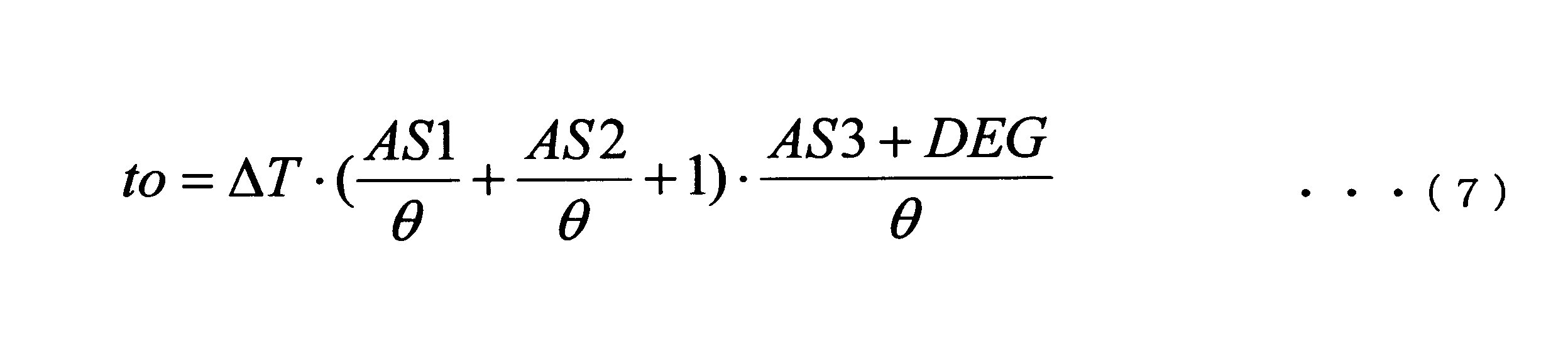
ここで、AS1は第1の信号を出力した回転位置センサの取付位置の誤差(上の例ではAS_v)であり、AS2は第2の信号を出力した回転位置センサの取付位置の誤差(上の例ではAS_u)であり、AS3は第3の信号を出力した回転位置センサの取付位置の誤差(上の例ではAS_w)であり、θはモータ3の電気角であり、DEGは出力角度算出部13により算出された出力角度である。
モータ制御部16は、算出されたデューティ比のPWM信号を電力変換部30に出力することによりモータ3を制御する。より詳しくは、モータ制御部16は、信号受信部11がセンサ信号S2の次に到来するセンサ信号S3をW相アングルセンサ4wから受信すると、センサ信号S3が受信されてから出力タイミング時間toが経過したときに電力変換部30にPWM信号を出力する。すなわち、図7に示すように、モータ制御部16は、センサ信号S3が受信されてから出力タイミング時間toが経過した時刻t4で電力変換部30にPWM信号を出力する。
本実施形態では、モータ制御部16は、センサ信号S3を受信すると、出力タイミング時間に相当するタイマー値を、制御部10が有するタイマー(図示せず)に設定する。そして、タイマーがタイムアウトすると、PWM信号を電力変換部30に送信する。なお、出力されるPWM信号のデューティ比は、センサ信号S3の受信後に出力角度算出部13により取得された値であってもよい。
上記のようにデューティ比マップM2から取得されたデューティ比を有するPWM信号が、アングルセンサ4u,4v,4wの取付位置の誤差を考慮した出力タイミングで電力変換部30に出力される。これにより、モータ3の効率を低下させることなく、所望のトルクを発生するようにモータ3を制御することができる。
上記の例では、U相アングルセンサ4uからセンサ信号を受信した場合の出力タイミング時間の算出処理について説明したが、タイミング決定部15は、W相アングルセンサ4wまたはV相アングルセンサ4vからセンサ信号を受信した場合も同様の処理を行って出力タイミング時間を算出してもよい。例えば、W相アングルセンサ4wからセンサ信号S3を受信した場合、タイミング決定部15は、センサ信号S2とセンサ信号S3間の信号間隔を算出し、誤差AS1としてU相アングルセンサ4uに係る誤差を用い、誤差AS2としてW相アングルセンサ4wに係る誤差を用い、誤差AS3としてV相アングルセンサ4vに係る誤差を用い、式(7)により出力タイミング時間を算出する。そして、モータ制御部16は、V相アングルセンサ4vからセンサ信号を受信すると、当該センサ信号を受信してから出力タイミング時間が経過した後にPWM信号を電力変換部30に出力する。このように、PWM信号の送信を開始するステージの前のステージにおいて、上述の出力タイミング時間の算出処理を行う。なお、上記方法に適用はPWM信号に限られず、半導体スイッチQ1~Q6をオン状態にするためのオン制御信号をインバータに出力するタイミングを上記方法により算出、決定してもよい。
以上説明したように、本実施形態に係る電動車両制御装置1では、信号間隔算出部12が、センサ信号S1とセンサ信号S2間の時間間隔である信号間隔を算出し、出力角度算出部13が、電力変換部30を制御するためのPWM信号の出力角度を算出し、取付誤差取得部14が、アングルセンサ4u,4v,4wの取付位置の誤差を取得する。そして、タイミング決定部15が、信号間隔、出力角度および各アングルセンサ4u,4v,4wに係る誤差に基づいてPWM信号の出力タイミング時間を決定し、モータ制御部16が、センサ信号S3を受信してから出力タイミング時間が経過した後にPWM信号を電力変換部30に出力する。
上記のように本実施形態では、モータ3の各相に対応付けて設けられたアングルセンサ4u,4v,4wの取付位置の誤差を考慮して決定された出力タイミングでPWM信号を出力する。このため、アングルセンサ4u,4v,4wの取付位置に誤差がある場合であっても、ロータ3rの回転位置に応じた正確なPWM制御を行うことができる。よって、本実施形態によれば、モータ3を適切に制御することができるようになり、モータの効率を向上させることができる。また、モータ3の効率が向上することで、バッテリ2の負荷が低減するため、バッテリ2の劣化を抑制することもできる。
<電動車両制御方法>
次に、図11のフローチャートを参照して、本実施形態に係る電動車両制御方法の一例について説明する。なお、カウント数は事前に初期化されているものとする。
次に、図11のフローチャートを参照して、本実施形態に係る電動車両制御方法の一例について説明する。なお、カウント数は事前に初期化されているものとする。
信号受信部11は、モニタ時間間隔Δtmが経過したかどうかを判定する(ステップS11)。モニタ時間間隔Δtmが経過した場合(S11:Yes)、アングルセンサ4からセンサ信号を受信したかどうかを判定する(ステップS12)。センサ信号を受信してない場合(S12:No)、カウント数を1つ増やして(ステップS13)、ステップS11に戻る。
一方、センサ信号を受信している場合(S12:Yes)、信号間隔算出部12は、センサ信号S1とセンサ信号S2との間にカウントされたカウント数を信号間隔ΔTとして算出し、カウント数を初期値にリセットする(ステップS14)。本ステップにおいて、信号間隔算出部12は、式(2)によりモータ3の瞬時回転速度を算出する。なお、カウント数のリセットはステップS15~S19のいずれのタイミングで行ってもよい。
次に、出力角度算出部13は、ステップS14で算出された瞬時回転速度と、アクセルポジションセンサ5から受信したアクセル操作量に基づいて、PWM信号のデューティ比と出力角度を求める(ステップS15)。具体的には、図8を参照して説明したように、トルクマップM1、デューティ比マップM2および出力角度マップM3を用いることでPWM信号のデューティ比と出力角度を求める。
次に、取付誤差取得部14は、各相のアングルセンサ4u,4v,4wの取付位置の誤差を取得する(ステップS16)。
次に、タイミング決定部15は、電力変換部30にPWM信号を出力するタイミングを決定する(ステップS17)。具体的には、信号受信部11がセンサ信号S3を受信するまでに、信号間隔ΔT、出力角度および誤差AS_u,AS_v,AS_wに基づいて、PWM信号の出力タイミング時間toを決定する。
次に、モータ制御部16は、出力タイミングであるか否かを判定する(ステップS18)。具体的には、センサ信号S3を受信してから、ステップS17で決定された出力タイミング時間が経過したか否かを判定する。出力タイミングであると判定された場合(S18:Yes)、モータ制御部16は、電力変換部30(インバータ)にPWM信号を送信する(ステップS19)。
上記の駆動方法によれば、アングルセンサ4u,4v,4wの取付位置の誤差を考慮してPWM信号の出力タイミングを決定するため、アングルセンサ4u,4v,4wの取付位置に誤差がある場合でも、適切なモータ制御を行うことができる。
なお、上記の処理フローではカウント数を用いたが、センサ信号の受信時刻を用いて信号間隔を算出し、瞬時回転速度を算出してもよい。また、センサ信号を受信していない場合(S12:No)に、直近のアクセル操作量と、前回算出された瞬時回転速度とを用いてデューティ比マップM2からデューティ比を取得してもよい。そして、取得されたデューティ比を用いて、電力変換部30に送信するPWM信号を更新してもよい。
上述した実施形態で説明した電動車両制御装置1(制御部10)の少なくとも一部は、ハードウェアで構成してもよいし、ソフトウェアで構成してもよい。ソフトウェアで構成する場合には、制御部10の少なくとも一部の機能を実現するプログラムをフレキシブルディスクやCD-ROM等の記録媒体に収納し、コンピュータに読み込ませて実行させてもよい。記録媒体は、磁気ディスクや光ディスク等の着脱可能なものに限定されず、ハードディスク装置やメモリなどの固定型の記録媒体でもよい。
また、制御部10の少なくとも一部の機能を実現するプログラムを、インターネット等の通信回線(無線通信も含む)を介して頒布してもよい。さらに、同プログラムを暗号化したり、変調をかけたり、圧縮した状態で、インターネット等の有線回線や無線回線を介して、あるいは記録媒体に収納して頒布してもよい。
上記の記載に基づいて、当業者であれば、本発明の追加の効果や種々の変形を想到できるかもしれないが、本発明の態様は、上述した個々の実施形態に限定されるものではない。異なる実施形態にわたる構成要素を適宜組み合わせてもよい。特許請求の範囲に規定された内容及びその均等物から導き出される本発明の概念的な思想と趣旨を逸脱しない範囲で種々の追加、変更及び部分的削除が可能である。
1 電動車両制御装置
2 バッテリ
3 モータ
3r ロータ
4 アングルセンサ
4u U相アングルセンサ
4v V相アングルセンサ
4w W相アングルセンサ
5 アクセルポジションセンサ
6 アシストスイッチ
7 メータ
8 車輪
9 充電器
10 制御部
11 信号受信部
12 信号間隔算出部
13 出力角度算出部
14 取付誤差取得部
15 タイミング決定部
16 モータ制御部
20 記憶部
30 電力変換部
100 電動車両
M1 トルクマップ
M2 デューティ比マップ
M3 出力角度マップ
Q1,Q2,Q3,Q4,Q5,Q6 半導体スイッチ
S1,S2,S3 センサ信号
2 バッテリ
3 モータ
3r ロータ
4 アングルセンサ
4u U相アングルセンサ
4v V相アングルセンサ
4w W相アングルセンサ
5 アクセルポジションセンサ
6 アシストスイッチ
7 メータ
8 車輪
9 充電器
10 制御部
11 信号受信部
12 信号間隔算出部
13 出力角度算出部
14 取付誤差取得部
15 タイミング決定部
16 モータ制御部
20 記憶部
30 電力変換部
100 電動車両
M1 トルクマップ
M2 デューティ比マップ
M3 出力角度マップ
Q1,Q2,Q3,Q4,Q5,Q6 半導体スイッチ
S1,S2,S3 センサ信号
Claims (15)
- 負荷を駆動するモータの各相に対応付けて設けられた複数の回転位置センサから出力され、前記モータの回転速度に応じた間隔で到来する信号を受信する信号受信部と、
前記信号受信部が第1の信号を受信した後、第2の信号を受信すると、前記第1の信号の受信時刻と前記第2の信号の受信時刻との間の信号間隔を算出する信号間隔算出部と、
前記モータの回転速度および目標トルクに基づいて、前記モータに交流電力を供給するインバータを制御するためのPWM信号の出力角度を算出する出力角度算出部と、
前記各回転位置センサの取付位置の誤差を取得する取付誤差取得部と、
前記信号受信部が前記第2の信号の次に到来する第3の信号を受信するまでに、前記信号間隔、前記出力角度、および前記各回転位置センサに係る前記誤差に基づいて前記PWM信号の出力タイミング時間を決定するタイミング決定部と、
前記第3の信号が受信されてから前記出力タイミング時間が経過したときに前記インバータにPWM信号を出力するモータ制御部と、
を備えることを特徴とする駆動装置。 - 前記モータは、第1の相、第2の相および第3の相を有し、
前記複数の回転位置センサは、前記第1の相に対応する第1の回転位置センサと、前記第2の相に対応する第2の回転位置センサと、前記第3の相に対応する第3の回転位置センサであり、
前記第1の信号は、前記第1の回転位置センサから出力されたものであり、
前記第2の信号は、前記第2の回転位置センサから出力されたものであり、
前記第3の信号は、前記第3の回転位置センサから出力されたものであり、
前記取付誤差取得部は、前記第1の回転位置センサに係る第1の誤差、前記第2の回転位置センサに係る第2の誤差、および前記第3の回転位置センサに係る第3の誤差を取得し、
前記タイミング決定部は、
前記第1の誤差および前記第2の誤差に基づいて前記信号間隔を補正し、
前記第3の誤差に基づいて前記出力角度を補正し、
前記補正された信号間隔に、前記補正された出力角度に対応する時間を乗じることにより、前記出力タイミング時間を算出することを特徴とする請求項1に記載の駆動装置。 - 前記モータは、第1の相、第2の相および第3の相を有し、
前記複数の回転位置センサは、前記第1の相に対応する第1の回転位置センサと、前記第2の相に対応する第2の回転位置センサと、前記第3の相に対応する第3の回転位置センサであり、
前記第1の信号は、前記第1の回転位置センサから出力されたものであり、
前記第2の信号は、前記第2の回転位置センサから出力されたものであり、
前記第3の信号は、前記第3の回転位置センサから出力されたものであり、
前記取付誤差取得部は、前記第1の回転位置センサに係る第1の誤差、前記第2の回転位置センサに係る第2の誤差、および前記第3の回転位置センサに係る第3の誤差を取得し、
前記タイミング決定部は、下式により前記出力タイミング時間を算出することを特徴とする請求項1に記載の駆動装置。

- 前記信号間隔算出部は、前記第1の信号を受信してから前記第2の信号を受信するまでにモニタ時間間隔ごとにカウントされたカウント数に、前記モニタ時間間隔を乗じることにより前記信号間隔を算出することを特徴とする請求項1に記載の駆動装置。
- 前記信号間隔算出部は、前記信号間隔を算出した後、前記カウント数をリセットすることを特徴とする請求項4に記載の駆動装置。
- 前記出力角度算出部は、前記モータの目標トルクと、前記モータの回転速度と、前記PWM信号の出力角度との関係を示す出力角度マップを、前記モータの目標トルクおよび前記回転速度を用いて検索することにより、前記出力角度を取得することを特徴とする請求項1に記載の駆動装置。
- 前記信号間隔算出部は、下式により得られる瞬時回転速度を前記モータの回転速度として用いて前記出力角度を算出することを特徴とする請求項1に記載の駆動装置。
n = 60000/(ΔT×Np)
ここで、nは前記モータの瞬時回転速度[rpm]であり、ΔTは前記信号間隔[mSec]であり、Npは前記モータが電気角で一回転する間に前記信号受信部が受信するセンサ信号の数である。 - 前記出力角度算出部は、前記モータの目標トルクと、前記モータの回転速度と、前記PWM信号のデューティ比との関係を示すデューティ比マップを、前記モータの目標トルクおよび前記回転速度を用いて検索することにより前記PWM信号のデューティ比を取得することを特徴とする請求項1に記載の駆動装置。
- 前記信号受信部が受信する前記信号は、前記複数の回転位置センサから出力されたパルス信号の立ち上がりエッジ信号および立ち下がりエッジ信号であることを特徴とする請求項1に記載の駆動装置。
- 前記誤差は、前記回転位置センサから前記信号が出力されたタイミングにおける前記モータの回転位置に基づいて得られる値であることを特徴とする請求項1に記載の駆動装置。
- 前記誤差は、前記モータを複数回回転させて得られた値の平均値であることを特徴とする請求項10に記載の駆動装置。
- 請求項1に記載の駆動装置であって、前記負荷が電動車両の車輪である、駆動装置を備えることを特徴とする電動車両。
- 前記車輪と前記モータがクラッチを介さずに機械的に接続されていることを特徴とする請求項12に記載の電動車両。
- 信号受信部が、負荷を駆動するモータに設けられた複数の回転位置センサから出力され、前記モータの回転速度に応じた間隔で到来する信号を受信するステップと、
信号間隔算出部が、前記信号受信部が第1の信号を受信した後、第2の信号を受信すると、前記第1の信号の受信時刻と前記第2の信号の受信時刻との間の信号間隔を算出するステップと、
出力角度算出部が、前記モータの回転速度および目標トルクに基づいて、前記モータに交流電力を供給するインバータを制御するためのPWM信号の出力角度を算出するステップと、
取付誤差取得部が、前記各回転位置センサの取付位置の誤差を取得するステップと、
タイミング決定部が、前記信号受信部が前記第2の信号の次に到来する第3の信号を受信するまでに、前記信号間隔、前記出力角度、および前記各回転位置センサに係る前記誤差に基づいて前記PWM信号の出力タイミング時間を決定するステップと、
モータ制御部が、前記第3の信号が受信されてから前記出力タイミング時間が経過したときに前記インバータにPWM信号を出力するステップと、
を備えることを特徴とする駆動方法。 - 信号受信部が、負荷を駆動するモータに設けられた複数の回転位置センサから出力され、前記モータの回転速度に応じた間隔で到来する信号を受信するステップと、
信号間隔算出部が、前記信号受信部が第1の信号を受信した後、第2の信号を受信すると、前記第1の信号の受信時刻と前記第2の信号の受信時刻との間の信号間隔を算出するステップと、
出力角度算出部が、前記モータの回転速度および目標トルクに基づいて、前記モータに交流電力を供給するインバータを制御するためのPWM信号の出力角度を算出するステップと、
取付誤差取得部が、前記各回転位置センサの取付位置の誤差を取得するステップと、
タイミング決定部が、前記信号受信部が前記第2の信号の次に到来する第3の信号を受信するまでに、前記信号間隔、前記出力角度、および前記各回転位置センサに係る前記誤差に基づいて前記PWM信号の出力タイミング時間を決定するステップと、
モータ制御部が、前記第3の信号が受信されてから前記出力タイミング時間が経過したときに前記インバータにPWM信号を出力するステップと、
をコンピュータに実行させる駆動プログラム。
Priority Applications (4)
| Application Number | Priority Date | Filing Date | Title |
|---|---|---|---|
| CN201880091333.6A CN111954978B (zh) | 2018-03-28 | 2018-03-28 | 驱动装置、驱动方法以及电动车辆 |
| PCT/JP2018/012746 WO2019186758A1 (ja) | 2018-03-28 | 2018-03-28 | 駆動装置、駆動方法、駆動プログラムおよび電動車両 |
| JP2020510291A JP6953622B2 (ja) | 2018-03-28 | 2018-03-28 | 駆動装置、駆動方法、駆動プログラムおよび電動車両 |
| TW108110616A TWI689426B (zh) | 2018-03-28 | 2019-03-27 | 驅動裝置、驅動方法、驅動程式以及電動車輛 |
Applications Claiming Priority (1)
| Application Number | Priority Date | Filing Date | Title |
|---|---|---|---|
| PCT/JP2018/012746 WO2019186758A1 (ja) | 2018-03-28 | 2018-03-28 | 駆動装置、駆動方法、駆動プログラムおよび電動車両 |
Publications (1)
| Publication Number | Publication Date |
|---|---|
| WO2019186758A1 true WO2019186758A1 (ja) | 2019-10-03 |
Family
ID=68059553
Family Applications (1)
| Application Number | Title | Priority Date | Filing Date |
|---|---|---|---|
| PCT/JP2018/012746 Ceased WO2019186758A1 (ja) | 2018-03-28 | 2018-03-28 | 駆動装置、駆動方法、駆動プログラムおよび電動車両 |
Country Status (4)
| Country | Link |
|---|---|
| JP (1) | JP6953622B2 (ja) |
| CN (1) | CN111954978B (ja) |
| TW (1) | TWI689426B (ja) |
| WO (1) | WO2019186758A1 (ja) |
Families Citing this family (1)
| Publication number | Priority date | Publication date | Assignee | Title |
|---|---|---|---|---|
| KR102724118B1 (ko) * | 2021-12-29 | 2024-10-30 | 현대오토에버 주식회사 | 모터 구동 회로의 pwm 신호 오차 보상 장치 및 방법 |
Citations (6)
| Publication number | Priority date | Publication date | Assignee | Title |
|---|---|---|---|---|
| JPS63163281A (ja) * | 1986-12-26 | 1988-07-06 | Koyo Denshi Kogyo Kk | デジタル回転計 |
| JPH09243668A (ja) * | 1996-03-12 | 1997-09-19 | Toshiba Corp | パルス信号の瞬時値測定方法およびその測定装置 |
| JP2003348876A (ja) * | 2002-05-22 | 2003-12-05 | Toshiba Corp | インバータ装置,半導体集積回路装置及び乗算装置 |
| JP2007330037A (ja) * | 2006-06-07 | 2007-12-20 | Sharp Corp | 制御装置および制御方法 |
| JP2013165575A (ja) * | 2012-02-10 | 2013-08-22 | Panasonic Corp | モータ駆動装置およびブラシレスモータ |
| US20160320205A1 (en) * | 2015-04-29 | 2016-11-03 | Freescale Semiconductor, Inc. | Counter based circuit for measuring movement of an object |
Family Cites Families (7)
| Publication number | Priority date | Publication date | Assignee | Title |
|---|---|---|---|---|
| TWI259648B (en) * | 2003-12-02 | 2006-08-01 | Ind Tech Res Inst | Method to control the DC brushless motor of electromotive car |
| KR100905022B1 (ko) * | 2007-09-14 | 2009-06-30 | 엘에스산전 주식회사 | 속도센서를 갖는 영구자석 동기 전동기용 인버터 및 그의고장 검출 방법 |
| JP5413424B2 (ja) * | 2011-08-24 | 2014-02-12 | パナソニック株式会社 | モータ駆動装置およびブラシレスモータ |
| CN103378800A (zh) * | 2012-04-18 | 2013-10-30 | 应广科技股份有限公司 | 可提高马达驱动运转效率的控制器与方法 |
| JP6026812B2 (ja) * | 2012-08-10 | 2016-11-16 | 日立オートモティブシステムズ株式会社 | モータ部およびインバータ部を備えたモータ制御装置 |
| JP6207458B2 (ja) * | 2014-05-13 | 2017-10-04 | 三菱電機株式会社 | 電動機の制御装置 |
| CN106464175B (zh) * | 2014-05-28 | 2018-03-13 | 松下知识产权经营株式会社 | 无刷电动机驱动装置 |
-
2018
- 2018-03-28 WO PCT/JP2018/012746 patent/WO2019186758A1/ja not_active Ceased
- 2018-03-28 CN CN201880091333.6A patent/CN111954978B/zh active Active
- 2018-03-28 JP JP2020510291A patent/JP6953622B2/ja active Active
-
2019
- 2019-03-27 TW TW108110616A patent/TWI689426B/zh not_active IP Right Cessation
Patent Citations (6)
| Publication number | Priority date | Publication date | Assignee | Title |
|---|---|---|---|---|
| JPS63163281A (ja) * | 1986-12-26 | 1988-07-06 | Koyo Denshi Kogyo Kk | デジタル回転計 |
| JPH09243668A (ja) * | 1996-03-12 | 1997-09-19 | Toshiba Corp | パルス信号の瞬時値測定方法およびその測定装置 |
| JP2003348876A (ja) * | 2002-05-22 | 2003-12-05 | Toshiba Corp | インバータ装置,半導体集積回路装置及び乗算装置 |
| JP2007330037A (ja) * | 2006-06-07 | 2007-12-20 | Sharp Corp | 制御装置および制御方法 |
| JP2013165575A (ja) * | 2012-02-10 | 2013-08-22 | Panasonic Corp | モータ駆動装置およびブラシレスモータ |
| US20160320205A1 (en) * | 2015-04-29 | 2016-11-03 | Freescale Semiconductor, Inc. | Counter based circuit for measuring movement of an object |
Also Published As
| Publication number | Publication date |
|---|---|
| JPWO2019186758A1 (ja) | 2021-02-25 |
| JP6953622B2 (ja) | 2021-10-27 |
| CN111954978B (zh) | 2024-01-05 |
| TWI689426B (zh) | 2020-04-01 |
| CN111954978A (zh) | 2020-11-17 |
| TW201945219A (zh) | 2019-12-01 |
Similar Documents
| Publication | Publication Date | Title |
|---|---|---|
| JP6953622B2 (ja) | 駆動装置、駆動方法、駆動プログラムおよび電動車両 | |
| CN111954977B (zh) | 驱动装置、驱动方法、计算机可读介质以及电动车辆 | |
| JP7162654B2 (ja) | 駆動装置、電動車両および駆動装置の制御方法 | |
| JP6862562B2 (ja) | 電動車両制御装置、電動車両制御方法、電動車両制御プログラムおよび電動車両 | |
| JP6972305B2 (ja) | 駆動装置、駆動方法、駆動プログラムおよび電動車両 | |
| JP6816296B2 (ja) | 電動車両制御装置、電動車両制御方法、電動車両制御プログラムおよび電動車両 | |
| JP7625383B2 (ja) | 駆動装置及び制御方法 | |
| JP7740868B2 (ja) | 制御装置及び制御方法 | |
| JP7451260B2 (ja) | 駆動装置、および、駆動装置の制御方法 | |
| JP7127115B2 (ja) | 駆動装置、電動車両および駆動装置の制御方法 | |
| JP7135069B2 (ja) | 駆動装置、電動車両および駆動装置の制御方法 | |
| CN111225818A (zh) | 电动车辆、电动车辆控制装置以及电动车辆控制方法 |
Legal Events
| Date | Code | Title | Description |
|---|---|---|---|
| 121 | Ep: the epo has been informed by wipo that ep was designated in this application |
Ref document number: 18911525 Country of ref document: EP Kind code of ref document: A1 |
|
| ENP | Entry into the national phase |
Ref document number: 2020510291 Country of ref document: JP Kind code of ref document: A |
|
| NENP | Non-entry into the national phase |
Ref country code: DE |
|
| 122 | Ep: pct application non-entry in european phase |
Ref document number: 18911525 Country of ref document: EP Kind code of ref document: A1 |