WO2019181775A1 - クランプ機構及び当該クランプ機構を備える基板保持装置 - Google Patents
クランプ機構及び当該クランプ機構を備える基板保持装置 Download PDFInfo
- Publication number
- WO2019181775A1 WO2019181775A1 PCT/JP2019/010800 JP2019010800W WO2019181775A1 WO 2019181775 A1 WO2019181775 A1 WO 2019181775A1 JP 2019010800 W JP2019010800 W JP 2019010800W WO 2019181775 A1 WO2019181775 A1 WO 2019181775A1
- Authority
- WO
- WIPO (PCT)
- Prior art keywords
- clamp
- substrate
- mounting table
- pin
- push
- Prior art date
- Legal status (The legal status is an assumption and is not a legal conclusion. Google has not performed a legal analysis and makes no representation as to the accuracy of the status listed.)
- Ceased
Links
Images




Classifications
-
- H—ELECTRICITY
- H10—SEMICONDUCTOR DEVICES; ELECTRIC SOLID-STATE DEVICES NOT OTHERWISE PROVIDED FOR
- H10P—GENERIC PROCESSES OR APPARATUS FOR THE MANUFACTURE OR TREATMENT OF DEVICES COVERED BY CLASS H10
- H10P72/00—Handling or holding of wafers, substrates or devices during manufacture or treatment thereof
- H10P72/70—Handling or holding of wafers, substrates or devices during manufacture or treatment thereof for supporting or gripping
Definitions
- the present invention relates to a clamp mechanism and a substrate holding device including the clamp mechanism.
- Patent Document 1 discloses a device in which a plurality of clamp mechanisms including a pair of clamp pieces that hold a substrate in between are installed. ing.
- the clamp mechanism used in the conventional substrate holding apparatus has a structure in which an elastic body is used to apply a force to hold the substrate between the pair of clamp pieces. For this reason, since it is necessary to incorporate an elastic body into the clamping mechanism, there is a problem that the structure becomes complicated and the productivity is poor. In addition, when trying to adjust the force to hold the substrate between the pair of clamp pieces, it is necessary to disassemble and assemble the clamp mechanism in order to replace the elastic body, which is very troublesome. .
- the main object of the present invention is to provide a clamping mechanism that can apply a force to hold the substrate with a simple structure.
- the clamping mechanism according to the present invention is a clamping mechanism that holds a substrate between the mounting table on which the substrate is mounted and the substrate mounted on the mounting table between the mounting table.
- a magnet provided and a magnetic body provided on the other are provided.
- the magnetic force of the magnet provided in the clamp holding mechanism may be weakened due to aging, the magnet and the magnetic body in the state where the clamp piece is closed with respect to the mounting table with respect to the clamp holding mechanism. It is desirable to further include a distance adjusting mechanism that adjusts the distance between them.
- the distance adjusting mechanism is specifically provided in at least one of the mounting table or the clamp piece, and has an insertion hole that is inserted so that one of the magnet or the magnetic body can move forward and backward with respect to the other. More specifically, the distance adjustment mechanism includes a male screw portion provided on the outer surface of the magnet or the magnetic body, and a female screw portion provided on the inner surface of the insertion hole. May be provided.
- At least one of the mounting table or the clamp piece includes a contact surface that comes into contact with one surface of the substrate, and a facing surface that rises from the contact surface and faces the end surface of the substrate.
- substrate with respect to a mounting base can be controlled with an opposing surface.
- the clamp piece may be configured to have an inclined surface inclined toward the tip on the surface opposite to the surface in contact with the substrate.
- the clamp mechanism may further include a clamp release mechanism that releases the closed state of the clamp piece with respect to the mounting table.
- the mounting table is provided with a through hole.
- the clamp release mechanism may be configured to include a push-up pin that is inserted into the through hole and pushes up the clamp piece with respect to the mounting table to open it.
- the insertion hole provided in order to insert a magnetic body or a magnet with respect to a mounting base can also be utilized now as a through-hole for inserting a push-up pin with respect to a mounting base.
- the clamp release mechanism further includes a push-up pin moving mechanism that moves the push-up pin relative to the clamp piece, and the push-up pin moving mechanism pushes the clamp piece up by inserting the push-up pin into the through hole.
- a clamp release position raised like this, a push-up pin standby position lowered so as to be pulled out from the through hole, and a push-up pin retracting position that does not hinder the movement of the substrate held by the clamp piece and the mounting table You may make it move between.
- the substrate held by the clamp mechanism is then transported to the processing chamber for processing, but the substrate held by the clamp mechanism is placed vertically so that dust or the like is less likely to adhere to the substrate during this processing.
- the push-up pin does not interfere with the substrate by moving the push-up pin to the push-up pin retracting position.
- the substrate holding device includes any one of the clamp mechanisms and a substrate delivery mechanism that delivers the substrate conveyed by the conveyance device to the clamp mechanism.
- the mounting table has a frame shape
- the substrate delivery mechanism passes the substrate transported above the mounting table by the transport device from below into the frame of the mounting table.
- a support pin moving mechanism for moving the support pin with respect to the mounting table. The support pin moving mechanism passes the support pin into the frame of the mounting table from below.
- the substrate support position raised to support the substrate, the support pin standby position lowered to the lower side of the mounting table, and the support that does not hinder the movement of the substrate sandwiched between the clamp piece and the mounting table What is necessary is just to comprise so that it may move between pin retraction positions, and more specifically, after the said push-up pin is moved to the said clamp release position and the said support pin is moved to the said board
- the substrate delivery mechanism is arranged in multiple stages in the substrate holding device and the substrate delivery mechanism is installed so as to correspond to the clamping mechanism of each stage, the substrate delivery After the substrate is transferred from the mechanism to the clamp mechanism, when the substrate is erected vertically, the push-up pin is moved to the push-up pin retracted position and the support pin is moved to the support pin retracted position.
- the push-up pin and the support pin do not interfere with the substrate.
- a plurality of substrates transferred by the transfer device can be transferred to the substrate holding device at a time, and the efficiency of the substrate transfer operation is improved.
- the substrate holding device according to the present invention is used, for example, to transport a substrate into a processing chamber when processing is performed on the substrate used in a display.
- the substrate holding device M includes a clamp mechanism 100 that holds the substrate S, and a substrate delivery mechanism 200 that transfers the substrate S transported by the transport device to the clamp mechanism 100. I have.
- the clamp mechanism 100 opens and closes so as to sandwich the mounting table 10 on which the substrate S is mounted and the substrate S mounted on the mounting table 10.
- Four clamping mechanisms 100 of the present embodiment are provided so as to hold each side of the substrate S.
- the mounting table 10 has an abutment surface 11a with which an upper surface 11 (a surface facing the clamp piece 20 side) abuts one surface S1 of the substrate S, and an abutment surface 11a. And a facing surface 11b facing the end surface S2 of the substrate S placed on the contact surface 11a and extending from the facing surface 11b to the opposite side of the contact surface 11a. Note that the facing surface 11b plays a role of regulating the positional deviation of the substrate S placed on the contact surface 11a. Further, the extending surface 11c is a surface on which the substrate S is not abutted, and a hinge portion 12 that rotatably supports the clamp piece 20 is provided on the end side thereof.
- the mounting table 10 is provided with through holes 14a penetrating from the surface facing the clamp piece 12 to the opposite surface on both ends thereof, and from the surface facing the clamp piece 12 closer to the center thereof.
- An insertion hole 14b penetrating to the opposite surface is provided. Specifically, both the through hole 14a and the insertion hole 14b penetrate from the extending surface 11c to the opposite surface.
- a plurality of insertion holes 14 b are provided intermittently along the longitudinal direction of the mounting table 10.
- the mounting table 10 in the present embodiment has a frame shape and has a rectangular shape in accordance with the substrate S. That is, the mounting tables 10 constituting each clamp mechanism 100 are connected to each other to form a frame shape. Therefore, the mounting table 11 has a structure in which the contact surface 11a is provided on the inner side and the extended surface 11c is provided on the outer side, and the extended surface 11c is more than the inner side in which the contact surface 11a is provided. The outer side provided with is thicker by the height of the opposing surface 11b.
- the clamp piece 20 is pivotally supported by the hinge portion 12 of the mounting table 10 and opens and closes with respect to the mounting table 10 with the shaft 13 as a fulcrum.
- the clamp piece 20 has a lower surface 21 (a surface facing the mounting table 10) extending to a position facing the contact surface 11 a of the mounting table 10, and the tip side facing the contact surface 11 a is the substrate S.
- the contact surface 21a is in contact with the other surface S3.
- the clamp piece 20 is provided with an inclined surface 22 which is inclined toward the tip on the surface opposite to the contact surface 21a.
- the clamp piece 20 since the clamp piece 20 will be in the state on the board
- the clamp holding mechanism 30 holds the mounting table 10 and the clamp piece 20 in a closed state with respect to the mounting table 10 by attracting the mounting table 10 and the clamp piece 20 to each other.
- the clamp holding mechanism 30 includes a magnet 31 provided on the mounting table 20 and a magnetic body 32 provided on the clamp piece 20.
- the magnet 31 is inserted and held in the insertion hole 14b provided on the extended surface 11c side that does not contact the substrate S while avoiding the contact surface 11a of the mounting table 10, and the magnetic body 32 is clamped.
- the lower surface 21 of the piece 20 is provided so as to face the magnet 31.
- the clamp holding mechanism 30 includes a distance adjusting mechanism 50 that adjusts the distance between the magnet 31 and the magnetic body 32 in a state where the clamp piece 20 is closed with respect to the mounting table 10.
- the distance adjusting mechanism 50 has an insertion hole 14b provided in the mounting table 10 as a part of the configuration, and the magnet 31 is inserted into the insertion hole 14b so that the magnet 31 can move forward and backward.
- the distance adjusting mechanism 50 includes a male screw portion 31a provided on the outer surface of the magnet 31 and a female screw portion 51a provided on the inner surface of the insertion hole 14b. By rotating with respect to the hole 14b, the magnet 31 can move in the insertion hole 14b.
- the clamp releasing mechanism 40 opens the clamp piece 20 in a closed state with respect to the mounting table 10. Specifically, a push-up pin 41 inserted through a through hole 14 a formed in the mounting table 10 and a push-up pin moving mechanism 42 that moves the push-up pin 41 are provided.
- the push-up pin moving mechanism 42 is provided outside the frame of the mounting table 10 (outside), and includes a shaft body 42a extending along the through direction of the through hole 14a, and a support piece 42b extending from the shaft body 42a in the orthogonal direction.
- a push-up pin 41 is provided on the distal end side of the support piece 42b.
- the push-up pin moving mechanism 42 moves the shaft body 42a up and down to move the push-up pin 41 so as to be inserted into and removed from the through hole 14a. Further, the push-up pin moving mechanism 42 moves the push-up pin 41 into and out of the frame of the mounting table 10 by turning (rotating) the shaft body 42a (see FIG. 5).
- two support pieces 42b extend from a shaft body 42a, and a push-up pin 41 is provided on each support piece 42b.
- Each push-up pin 41 is inserted into and removed from a through-hole 14 a provided in two adjacent mounting tables 10.
- the substrate delivery mechanism 200 delivers the substrate S transported from the transport device to the clamp mechanism 100.
- the substrate delivery device 200 includes a support pin 210 that supports the substrate S, and a support pin moving mechanism 220 that moves the support pin 210.
- the support pin moving mechanism 220 includes a shaft body 220a that is installed outside the frame of the mounting table 10 and extends parallel to the shaft body 42a of the push-up pin moving mechanism 42, and a support piece 220b that extends from the shaft body 220a in the orthogonal direction.
- a support pin 210 is provided on the front end side of the support piece 220b.
- the substrate delivery mechanism 200 moves the shaft body 220a up and down to pass the support pins 210 from the lower side of the mounting table 10 into the frame thereof and move so as to contact the substrate S conveyed by the conveyance device. Let Further, the substrate delivery mechanism 200 moves the support pin 210 into and out of the frame of the mounting table 10 by turning (rotating) the shaft body 220a (see FIG. 5).
- the substrate holding device M further includes a control unit (not shown).
- the control unit has a so-called computer including a CPU, a memory, an A / D / D / A converter, etc., and a program stored in the memory is executed, and various functions cooperate with each other. Is to be realized. Specifically, the control unit delivers the substrate S transported by the transport device to the clamp mechanism 100 by cooperating the clamp release mechanism 40 and the substrate delivery mechanism 200, and sandwiches the substrate S by the clamp mechanism 100. Demonstrate the function to hold.
- the mounting operation of the substrate S in the substrate holding apparatus M according to the present invention will be described with reference to FIGS. 6 and 7, the operation of the substrate delivery mechanism 200 is illustrated on the left side with respect to the substrate S, and the operation of the clamp release mechanism 40 is illustrated on the right side, in order to simplify the drawings.
- the control unit lifts the push-up pin 41 below the through hole 14 a of the mounting table 10. While moving to the pin standby position xp1, the support pin 210 is moved to the support pin standby position xp2, which is the lower side in the frame of the mounting table 10. In this state, the clamp piece 20 is closed with respect to the mounting table 10 by its own weight.
- the control unit moves the push-up pin 41 into the through hole 14a to the clamp release position yp1 that is lifted so as to push up the clamp piece 20, and mount the support pin 210.
- the substrate is moved to the substrate support position yp ⁇ b> 2 that has been lifted so as to support the substrate S through the frame of the table 10 from below.
- the clamp piece 40 is pushed up by the push-up pins 41 and opened with respect to the mounting table 10, and the substrate S is supported from below by the support pins 210.
- the substrate S is delivered from the transfer device T to the substrate delivery mechanism 200.
- the control unit lowers the support pin 210 to the lower side in the frame of the mounting table 10 with the push-up pin 41 held at the clamp release position yp1, and waits for the support pin. Move to position xp2. Thereby, the substrate S is delivered from the substrate delivery mechanism 200 to the clamp mechanism 100 while the support pins 210 are lowered.
- the control unit lowers the push-up pin 41 so as to be pulled out from the through hole 14a, and moves it to the push-up pin standby position xp1.
- the clamp piece 20 will be in the state closed with respect to the mounting base 10 by dead weight again.
- the substrate S is sandwiched and held by each clamp mechanism 100 with an appropriate force.
- the controller turns the push-up pin 41 and moves to the push-up pin retracting position zp 1 that does not hinder the subsequent movement of the substrate S sandwiched between the mounting table 10 and the clamp piece 20.
- the support pin 210 is turned and moved to the support pin retracting position zp2 that does not hinder the subsequent movement of the substrate S sandwiched between the mounting table 10 and the clamp piece 20 (see FIG. 5).
- the push-up pin retracting position zp1 and the support pin retracting position zp2 are outside the frame of the mounting table 10. Accordingly, in consideration of subsequent processing on the substrate S, the clamp release mechanism 40 and the substrate delivery mechanism 200 do not interfere with the substrate S even when the substrate S is vertically set up on the spot.
- the clamp release mechanism 40 may be configured to further move down with respect to the mounting table 10 after the push-up pin 41 is moved to the push-up pin retracting position zp1, and the substrate delivery mechanism 200 includes the support pin 210. You may comprise so that it may descend
- the magnet for the magnetic body 32 when adjusting the force for clamping the substrate S by the clamp mechanism 100, as shown in FIG. 3, the magnet for the magnetic body 32 in a state where the clamp piece 20 is closed with respect to the mounting table 10 by the distance adjustment mechanism 50. Change the distance of 31.
- the distance of the magnet 31 with respect to the magnetic body 32 may be lengthened, since the attractive force by magnetic force will fall, the force which pinches
- the distance of the magnet 31 with respect to the body 32 is adjusted to be short, the attracting force due to the magnetic force is increased, so that the force for sandwiching the substrate S by the clamp mechanism 100 can be increased.
- the magnet 31 was provided in the mounting base 10 side as the clamp holding mechanism 30, it is good also as a structure which provides the magnet 31 in the clamp piece 20 side, without being limited to this. Moreover, it is good also as a structure which provides a magnet in both the mounting base 10 and the clamp piece 20.
- FIG. it is necessary to arrange the magnets 31 provided on the mounting table 10 and the magnets 31 provided on the clamp piece 20 so that different polarities face each other so as to attract each other. Further, the entire mounting table 10 or the clamp piece 20 may be formed by the magnet 31 or the magnetic body 32.
- the insertion hole 14b was provided in the mounting base 10 side as the distance adjustment mechanism 50, it is not limited to this, You may provide the insertion hole 14b in the clamp piece 20 side, The insertion hole 14 b may be provided in both the mounting table 10 and the clamp piece 20.
- the hole which penetrates the mounting base 10 is employ
- the distance adjusting mechanism 50 is configured such that the magnet 31 can be moved with respect to the insertion hole 14b by screwing the male screw part 31a of the magnet 31 and the female screw part 51a of the insertion hole 14b.
- the mounting base 10 was made into the frame shape, it is not limited to this, What is necessary is just a structure which can mount the board
- FIG. For example, a configuration may be adopted in which the four corners of the substrate are supported by a separate clamping mechanism 100.
- the substrate S is processed while being held by the substrate holding device M. At this time, dust or the like is not attached to the processing surface of the substrate S (the other surface S3 in the embodiment). Processing may be performed with the substrate S standing vertically. Therefore, the substrate holding device M may be connected to a movable base (not shown) that is in a horizontal state or a vertical state. Incidentally, according to the substrate holding device M according to the above embodiment, the clamp piece 20 is held in a closed state with respect to the mounting table 10 by the clamp holding mechanism 30 even in the vertical state, so that the substrate S is mounted on the mounting table. 10 can be prevented from falling off.
- the clamp release mechanism 40 is moved to the push-up pin retracted position and the substrate delivery mechanism 200 is moved to the support pin retracted position, so that these mechanisms do not interfere with the substrate S.
- maintenance apparatus M is shown, the aspect which installed two or more stages of the clamp mechanisms 100 may be sufficient.
- the clamp mechanism 100 may be arranged in two or more stages in the vertical direction.
- the substrate delivery mechanism 200 is also installed corresponding to each clamp mechanism 100.
- a configuration in which the push-up pin 41 is turned into and out of the frame of the mounting table 10 by the clamp release mechanism 40 as in the above embodiment, and the support pin 210 is mounted by the substrate delivery mechanism 200 is used. By adopting the configuration of turning into and out of the frame 10, these mechanisms do not hinder the subsequent movement of the substrate S.
- the structure which rotates the push-up pin 41 in and out of the frame of the mounting base 10 as the clamp release mechanism 40 is employ adopted, the structure which moves the push-up pin 41 in and out of the frame of the mounting base 10 is adopted.
- the substrate delivery mechanism 200 a configuration in which the support pins 210 are translated in and out of the frame of the mounting table 10 may be employed.
- M substrate holding device 100 clamping mechanism 10 mounting table 11a contact surface 11b facing surface 11c extending surface 14a through hole 14b insertion hole 20 clamp piece 21a contact surface 22 inclined surface 30 clamp holding mechanism 31 magnet 31a male screw part 32 magnetic body 40 Clamp release mechanism 41 Push-up pin 42 Push-up pin moving mechanism xp1 Push-up pin standby position yp1 Clamp release position zp1 Push-up pin retracting position 50 Distance adjustment mechanism 51a Female screw part 200 Substrate delivery mechanism 210 Support pin 220 Support pin movement mechanism xp2 Support pin standby Position yp2 Substrate support position zp2 Support pin retract position
Landscapes
- Container, Conveyance, Adherence, Positioning, Of Wafer (AREA)
Abstract
簡単な構造で基板を挟んで保持する力を付与することができるクランプ機構を提供する。基板を挟んで保持するクランプ機構であって、前記基板が載置される載置台と、前記載置台に載置された前記基板を当該載置台との間で挟むように開閉するクランプ片と、前記載置台に対して前記クランプ片を閉じた状態に保持するクランプ保持機構とを備え、前記クランプ保持機構が、前記載置台又は前記クランプ片のいずれか一方に設けられた磁石と他方に設けられた磁性体とを備える。
Description
本発明は、クランプ機構及び当該クランプ機構を備える基板保持装置に関するものである。
従来からディスプレイに用いられる基板を保持して搬送する基板保持装置としては、例えば、特許文献1には、基板を挟んで保持する一対のクランプ片を備えたクランプ機構を複数設置したものが開示されている。
ところで、前記従来の基板保持装置に用いられるクランプ機構は、弾性体を利用して一対のクランプ片に対し、基板を挟んで保持する力を付与する構造になっている。このため、クランプ機構に対し、弾性体を組み込む必要があることから構造が複雑になり、生産性が悪いという問題点があった。また、一対のクランプ片の基板を挟んで保持する力を調節しようとすると、弾性体を交換するために、クランプ機構を分解・組立する必要が生じ、非常に手間が掛るという問題点があった。
そこで、本発明は、簡単な構造で基板を挟んで保持する力を付与することができるクランプ機構を提供することを主な課題とするものである。
すなわち、本発明に係るクランプ機構は、基板を挟んで保持するクランプ機構であって、前記基板が載置される載置台と、前記載置台に載置された前記基板を当該載置台との間で挟むように開閉するクランプ片と、前記載置台に対して前記クランプ片を閉じた状態に保持するクランプ保持機構とを備え前記クランプ保持機構が、前記載置台又は前記クランプ片のいずれか一方に設けられた磁石と他方に設けられた磁性体とを備えるものである。
このようなものであれば、載置台に対してクランプ片を閉じた状態に保持する力を磁力による吸着によって付与する構造にしたので、その構造を簡素化でき、クランプ機構の組立てが容易となって生産性が向上する。
また、前記クランプ保持機構が備える磁石は、経年劣化によって磁力が弱まることがあることから、クランプ保持機構に対し、前記載置台に対して前記クランプ片が閉じた状態における前記磁石及び前記磁性体の間の距離を調節する距離調節機構をさらに備えることが望ましい。
このようなものであれば、磁力が弱まった磁石及び磁性体の間の距離を短く調節することができるようになり、載置台に対してクランプ片を閉じた状態に保持する力を元に戻すことができるようになる。これにより、磁石の磁力が極端に弱まるような事態が生じない限り、磁石を交換する必要がなくなる。
なお、前記距離調節機構は、具体的には、前記載置台又は前記クランプ片の少なくとも一方に設けられ、前記磁石又は前記磁性体の一方が他方に対して進退できるように挿入される挿入孔を有するように構成すればよく、より具体的には、前記距離調節機構が、前記磁石又は前記磁性体の外面に設けられた雄ネジ部と、前記挿入孔の内面に設けられた雌ネジ部とを備えるように構成すればよい。
このようなものであれば、挿入孔に対して磁石又は磁性体を移動させるだけで、載置台に対してクランプ片を閉じた状態に保持する力を調節することができるようになる。また、挿入孔に対して磁石又は磁性体を螺合させる構造にすることにより、磁石又は磁性体を回転させるだけで、磁石又は磁性体を挿入孔に対して移動させることができるようになる。
また、前記クランプ機構として、前記載置台又は前記クランプ片の少なくとも一方が、前記基板の片面と当接する当接面と、当該当接面から立ち上がって当該基板の端面と対向する対向面とを有するように構成してもよい。
このようなものであれば、対向面によって載置台に対する基板の位置ズレを規制することができるようになる。
また、前記クランプ機構として、前記クランプ片が、前記基板と当接する面と反対面に先端に向かって傾斜する傾斜面を有するように構成してもよい。
このようなものであれば、クランプ片が当接する基板の面に対して処理が施される場合に、当該面にクランプ片による影が形成され難くなり、当該面のクランプ機構周辺に処理ムラができ難くなる。
また、前記クランプ機構として、前記載置台に対して前記クランプ片が閉じた状態を解除するクランプ解除機構をさらに備えるものであってもよく、この場合、前記載置台に貫通孔が設けられており、前記クランプ解除機構が、前記貫通孔に差し込まれ、前記載置台に対して前記クランプ片を押し上げて開いた状態にする押上ピンを備えているように構成すればよい。
このようなものであれば、載置台に対して磁性体又は磁石を挿入するために設けた挿入孔を、載置台に対して押上ピンを挿通するための貫通孔としても利用できるようになる。これにより、載置台に対して押上ピンを挿通するための貫通孔を挿通孔とは別に設ける必要がなくなり、載置台の強度を高く保つことができる。また、載置台の加工作業を簡略化することができる。
また、前記クランプ解除機構が、前記押上ピンを前記クランプ片に対して移動させる押上ピン移動機構をさらに備え、前記押上ピン移動機構が、前記押上ピンを、前記貫通孔に差し込み前記クランプ片を押し上げるように上昇させたクランプ解除位置と、前記貫通孔から引き抜くように下降させた押上ピン待機位置と、前記クランプ片及び前記載置台によって保持された前記基板の動きを妨げない押上ピン退避位置との間で移動させるようにしてもよい。
クランプ機構によって保持された基板は、その後処理室へと搬送されて処理されるが、この処理中に基板に対して埃等が付着し難いように、このクランプ機構によって保持された基板を垂直に立てる場合があるが、このような構成であれば、クランプ機構によって保持された基板を垂直に立てる際に、押上ピンを押上ピン退避位置へ移動させることにより、押上ピンが基板と干渉しなくなる。
また、本発明に係る基板保持装置は、前記いずれかのクランプ機構と、搬送装置によって搬送される前記基板を前記クランプ機構へ受け渡す基板受渡機構とを備えるものである。
この場合、前記載置台が、枠状のものであり、前記基板受渡機構が、前記搬送装置によって前記載置台の上方へ搬送された前記基板を、前記載置台の枠内に下側から通されて支持する支持ピンと、前記載置台に対して前記支持ピンを移動させる支持ピン移動機構とを備え、前記支持ピン移動機構が、前記支持ピンを、前記載置台の枠内に下側から通して前記基板を支持するように上昇させた基板支持位置と、前記載置台の下側へ下降させた支持ピン待機位置と、前記クランプ片及び前記載置台によって挟まれた前記基板の動きを妨げない支持ピン退避位置との間で移動させるように構成すればよく、より具体的には、前記押上ピンを前記クランプ解除位置へ移動させ、前記支持ピンを前記基板支持位置へ移動させた後、前記支持ピンを前記支持ピン待機位置へ移動させる途中で、前記支持ピンによって支持された前記基板を前記クランプ機構に受け渡すと共に、前記押上ピンを前記押上ピン待機位置へ移動させ、その後、前記押上ピンを前記押上ピン退避位置へ移動させると共に、前記支持ピンを前記支持ピン退避位置へ移動させるように構成すればよい。
このような構成であれば、基板保持装置において、クランプ機構が多段状に配置され、当該各段のクランプ機構に対応するように基板受渡機構が設置されるような場合であっても、基板受渡機構からクランプ機構に対して基板が受け渡された後、その基板を垂直に立てる際に、押上ピンを押上ピン退避位置へ移動させると共に、支持ピンを支持ピン退避位置へ移動させれば、当該押上ピン及び当該支持ピンが基板と干渉しなくなる。これにより、搬送装置によって搬送される基板を複数枚一度に基板保持装置へ受け渡すことができるようになり、基板搬送作業の効率が向上する。
このような構成のクランプ機構によれば、簡単な構造で基板を挟んで保持する力を付与することができるようになる。
以下に、本発明に係るクランプ機構及び当該クランプ機構を備えた基板保持装置を図面に基づいて説明する。
本発明に係る基板保持装置は、例えば、ディスプレイに用いられる基板に対して処理を施す場合に、その基板を処理室内へ搬送するために使用されるものである。
<実施形態>
本実施形態に係る基板保持装置Mは、図1に示すように、基板Sの保持するクランプ機構100と、搬送装置によって搬送される基板Sをクランプ機構100へ受け渡す基板受渡機構200と、を備えている。
本実施形態に係る基板保持装置Mは、図1に示すように、基板Sの保持するクランプ機構100と、搬送装置によって搬送される基板Sをクランプ機構100へ受け渡す基板受渡機構200と、を備えている。
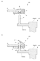
前記クランプ機構100は、図2(a)及び図2(b)に示すように、基板Sが載置される載置台10と、載置台10に載置された基板Sを挟むように開閉するクランプ片20と、載置台10に対してクランプ片20を閉じた状態に保持するクランプ保持機構30と、載置台10に対してクランプ片20が閉じた状態を解除するクランプ解除機構40と、を備えている。本実施形態のクランプ機構100は、基板Sの各辺を保持するように四つ設けられている。
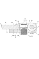
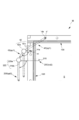
前記載置台10には、図3及び図4に示すように、その上面11(クランプ片20側を向く面)に、基板Sの一方面S1が当接する当接面11aと、当接面11aから立ち上がって当接面11aに載置された基板Sの端面S2と対向する対向面11bと、対向面11bから当接面11aと反対側へ延びる延設面11cと、が設けられている。なお、対向面11bは、当接面11aに載置された基板Sの位置ズレを規制する役割を果たしている。また、延設面11cは、基板Sが当接されない面であり、その端側にクランプ片20を回転可能に軸支するヒンジ部12が設けられている。
また、前記載置台10には、その両端側にクランプ片12と対向する面からその反対面へ貫通する貫通孔14aが設けられていると共に、その中央寄りにクランプ片12と対向する面からその反対面へ貫通する挿入孔14bが設けられている。具体的には、貫通孔14a及び挿入孔14bは、いずれも延設面11cからその反対面へ貫通している。挿入孔14bは、載置台10の長手方向に沿って間欠的に複数設けられている。
なお、本実施形態における載置台10は、図1に示すように、枠状のものであり、基板Sに合わせて矩形状になっている。すなわち、各クランプ機構100を構成する載置台10は、互いに繋がって枠状をなしている。よって、載置台11は、その内側に当接面11aが設けられ、その外側に延設面11cが設けられた構造になっており、当接面11aが設けられた内側よりも延設面11cが設けられた外側の方が対向面11bの高さの分だけ分厚くなっている。
前記クランプ片20は、載置台10のヒンジ部12に軸支され、その軸13を支点として当該載置台10に対して開閉するものである。なお、クランプ片20は、その下面21(載置台10側を向く面)が、載置台10の当接面11aと対向する位置まで延びており、その当接面11aと対向する先端側が基板Sの他方面S3と当接する当接面21aとなっている。また、クランプ片20には、当接面21aと反対面に先端に向かって傾斜する傾斜面22が設けられている。なお、クランプ片20は、基板S上に乗った状態になるため、比較的軽い材料によって形成されており、例えば、アルミニウムによって形成されている。
前記クランプ保持機構30は、図4に示すように、載置台10及びクランプ片20を磁力によって互いに吸着させることにより、載置台10に対してクランプ片20を閉じた状態に保持するものである。具体的には、クランプ保持機構30は、載置台20に設けられた磁石31と、クランプ片20に設けられた磁性体32と、を備えている。なお、磁石31は、載置台10の当接面11aを避けて基板Sと当接しない延設面11c側に設けられた挿入孔14bに挿入して保持されており、磁性体32は、クランプ片20の下面21に磁石31と対向するように設けられている。
また、前記クランプ保持機構30は、載置台10に対してクランプ片20が閉じた状態における磁石31及び磁性体32の間の距離を調節する距離調節機構50を備えている。具体的には、距離調節機構50は、載置台10に設けられた挿入孔14bを構成の一部としており、その挿入孔14bに磁石31が磁性体32に対して進退できるように挿入される。より具体的には、距離調節機構50は、磁石31の外面に設けられた雄ネジ部31aと、挿入孔14bの内面に設けられた雌ネジ部51aと、を備えており、磁石31を挿入孔14bに対して回転させることにより、磁石31が挿入孔14b内を移動できるようになっている。
前記クランプ解除機構40は、図2に示すように、載置台10に対して閉じた状態のクランプ片20を開いた状態にするものである。具体的には、載置台10に形成された貫通孔14aに挿通される押上ピン41と、押上ピン41を移動させる押上ピン移動機構42と、を備えている。
前記押上ピン移動機構42は、載置台10の枠外(外側)に設置され、貫通孔14aの貫通方向に沿って延びる軸体42aと、軸体42aから直交方向へ延びる支持片42bと、を備えており、支持片42bの先端側に、押上ピン41が設けられている。そして、押上ピン移動機構42は、軸体42aを上下に移動させることにより、押上ピン41を貫通孔14aに抜き差しするように移動させる。また、押上ピン移動機構42は、軸体42aを旋回(回転)させることにより、押上ピン41を載置台10の枠内外へ移動させる(図5参照)。
なお、本実施形態のクランプ解除機構40は、軸体42aから二つの支持片42bが延びており、それぞれの支持片42bに押上ピン41が設けられている。そして、各押上ピン41は、隣接する二つの載置台10に設けられた貫通孔14aにそれぞれ抜き差しされるようになっている。
前記基板受渡機構200は、搬送装置から搬送される基板Sをクランプ機構100に受け渡すものである。具体的には、基板受渡装置200は、基板Sを支持する支持ピン210と、支持ピン210を移動させる支持ピン移動機構220と、を備えている。
前記支持ピン移動機構220は、載置台10の枠外に設置され、押上ピン移動機構42の軸体42aと平行に延びる軸体220aと、軸体220aから直交方向へ延びる支持片220bと、を備えており、支持片220bの先端側に、支持ピン210が設けられている。そして、基板受渡機構200は、軸体220aを上下に移動させることにより、支持ピン210を載置台10の下側からその枠内に通し、搬送装置によって搬送される基板Sに当接するように移動させる。また、基板受渡機構200は、軸体220aを旋回(回転)させることにより、支持ピン210を載置台10の枠内外へ移動させる(図5参照)。
また、前記基板保持装置Mは、図示しない制御部をさらに有している。なお、制御部は、CPU、メモリ、A/D・D/Aコンバータ等を備えた所謂コンピュータを有し、前記メモリに格納されているプログラムが実行され、各種機器が協働することによって各機能が実現されるようにしてある。具体的には、制御部は、クランプ解除機構40及び基板受渡機構200を協働させることにより、搬送装置によって搬送される基板Sをクランプ機構100へ受け渡し、そのクランプ機構100によって基板Sを挟んで保持する機能を発揮させる。
次に、本発明に係る基板保持装置Mにおける基板Sの載置動作を図6及び図7に基づいて説明する。なお、図6及び図7においては、図面を簡略化するため、基板Sに対し、左側に基板受渡機構200の動作を図示し、右側にクランプ解除機構40の動作を図示している。
先ず、図6(a)に示すように、搬送装置Tによって載置台20の上方に基板Sが搬送されると、制御部は、押上ピン41を載置台10の貫通孔14a下側である押上ピン待機位置xp1へ移動させると共に、支持ピン210を載置台10の枠内下側である支持ピン待機位置xp2へ移動させる。なお、この状態で、クランプ片20は、自重によって載置台10に対して閉じた状態になっている。
次に、制御部は、図6(b)に示すように、押上ピン41を貫通孔14aに差し込みクランプ片20を押し上げるように上昇させたクランプ解除位置yp1へ移動させると共に、支持ピン210を載置台10の枠内に下側から通して基板Sを支持するように上昇させた基板支持位置yp2へ移動させる。これにより、クランプ片40は、押上ピン41によって押し上げられて載置台10に対して開いた状態となり、また、基板Sは、支持ピン210によって下側から支持された状態となる。そして、基板Sが、搬送装置Tから基板受渡機構200へ受け渡される。
次に、制御部は、図6(c)に示すように、押上ピン41をクランプ解除位置yp1に留めた状態で、支持ピン210を載置台10の枠内下側へ下降させて支持ピン待機位置xp2へ移動させる。これにより、支持ピン210が下降する途中で、基板Sが、基板受渡機構200からクランプ機構100へ受け渡される。
次に、制御部は、図7(d)に示すように、押上ピン41を貫通孔14aから引き抜くように下降させて押上ピン待機位置xp1へ移動させる。これにより、クランプ片20は、再び自重によって載置台10に対して閉じた状態となる。なお、この状態で、載置台10及びクランプ片20は、クランプ保持機構30によって互いに磁力によって吸着されるため、各クランプ機構100によって基板Sが適切な力で挟まれ保持された状態となる。
そして、制御部は、図7(e)に示すように、押上ピン41を旋回し、載置台10及びクランプ片20によって挟まれた基板Sのその後の動きを妨げない押上ピン退避位置zp1へ移動させると共に、支持ピン210を旋回し、載置台10及びクランプ片20によって挟まれた基板Sのその後の動きを妨げない支持ピン退避位置zp2へ移動させる(図5参照)。なお、本実施形態の押上ピン退避位置zp1及び支持ピン退避位置zp2は、載置台10の枠外である。これにより、基板Sに対するその後の処理を考慮し、その基板Sをその場で垂直に立てる場合であっても、クランプ解除機構40及び基板受渡機構200が基板Sに干渉しなくなる。
なお、クランプ解除機構40は、押上ピン41を押上ピン退避位置zp1へ移動させた後、載置台10に対してさらに下降するように構成してもよく、基板受渡機構200は、支持ピン210を支持ピン退避位置zp2へ移動させた後、載置台10に対してさらに下降するように構成してもよい。このようにすれば、その場で基板Sを垂直に立てる場合に、基板Sの可動スペースをより広く取ることができる。
また、クランプ機構100による基板Sを挟む力を調節する場合には、図3に示すように、距離調節機構50によって、載置台10に対してクランプ片20を閉じた状態における磁性体32に対する磁石31の距離を変更する。なお、磁性体32に対する磁石31の距離を長くするように調節した場合には、磁力による吸着力が低下するため、クランプ機構100による基板Sを挟む力を低下させることができ、逆に、磁性体32に対する磁石31の距離を短くするように調節した場合には、磁力による吸着力が上昇するため、クランプ機構100による基板Sを挟む力を増加させることができる。
<その他の実施形態>
前記実施形態においては、クランプ保持機構30として、載置台10側に磁石31を設ける構成としたが、これに限定されることなく、クランプ片20側に磁石31を設ける構成としてもよい。また、載置台10及びクランプ片20の両方に磁石を設ける構成としてもよい。この場合、載置台10に設けられた磁石31とクランプ片20に設けられた磁石31とが互いに吸着するように異なる極性が向かい合うように配置する必要がある。また、載置台10又はクランプ片20の全体を、磁石31又は磁性体32によって形成してもよい。
前記実施形態においては、クランプ保持機構30として、載置台10側に磁石31を設ける構成としたが、これに限定されることなく、クランプ片20側に磁石31を設ける構成としてもよい。また、載置台10及びクランプ片20の両方に磁石を設ける構成としてもよい。この場合、載置台10に設けられた磁石31とクランプ片20に設けられた磁石31とが互いに吸着するように異なる極性が向かい合うように配置する必要がある。また、載置台10又はクランプ片20の全体を、磁石31又は磁性体32によって形成してもよい。
また、前記実施形態においては、距離調節機構50として、載置台10側に挿入孔14bを設けたが、これに限定されることなく、クランプ片20側に挿入孔14bを設けてもよく、また、載置台10及びクランプ片20の両方に挿入孔14bを設けてもよい。なお、前記実施形態においては、挿入孔14bとして載置台10を貫通する孔を採用しているが、載置台10を貫通しない孔であってもよい。
また、前記実施形態においては、距離調節機構50として、磁石31の雄ネジ部31aと挿入孔14bの雌ネジ部51aとの螺合によって、挿入孔14bに対して磁石31を移動できるように構成したが、挿入孔14bに対して磁石31を摺動によって移動できるように構成してもよい。
また、前記実施形態においては、載置台10を枠状にしたが、これに限定されず、基板Sを載置できるような構成であればよい。例えば、別体からなるクランプ機構100で基板の四隅を支持するような構成にしてもよい。
また、基板Sは、基板保持装置Mに保持された状態で処理が施されるが、この時、基板Sの処理面(前記実施形態では他方面S3)に対して埃等が付着しないように基板Sを垂直に立てた状態で処理が実施されることがある。そこで、基板保持装置Mを水平状態又は垂直状態にする可動台(図示せず)に接続してもよい。因みに、前記実施形態に係る基板保持装置Mによれば、垂直状態にしても、クランプ保持機構30によって載置台10に対してクランプ片20が閉じた状態に保持されるため、基板Sが載置台10から脱落することを防止できる。また、基板保持装置Mを垂直状態にした場合に、載置台10の対向面11bに基板Sの端面S2が引っ掛かり、載置台10に対する基板Sの位置ズレが規制される。さらに、クランプ解除機構40を押上ピン退避位置へ移動させると共に、基板受渡機構200を支持ピン退避位置へ移動させることにより、これらの機構が基板Sへ干渉しなくなる。
また、前記実施形態においては、基板保持装置Mとしてクランプ機構100を一段だけ設置した態様を示しているが、クランプ機構100を二段以上設置した態様であってもよい。具体的には、クランプ機構100を上下方向に二段以上配置した態様であってもよい。なお、この場合、各クランプ機構100に対応させて基板受渡機構200も設置する。このような態様であっても、前記実施形態のようにクランプ解除機構40によって押上ピン41を載置台10の枠内外へ旋回する構成を採用すると共に、基板受渡機構200によって支持ピン210を載置台10の枠内外へ旋回する構成を採用することにより、これらの機構が、基板Sのその後の動きの妨げにならなくなる。
また、前記実施形態においては、クランプ解除機構40として押上ピン41を載置台10の枠内外へ旋回させる構成を採用しているが、押上ピン41を載置台10の枠内外へ平行移動させる構成を採用してもよく、同様に基板受渡機構200として支持ピン210を載置台10の枠内外へ平行移動させる構成を採用してもよい。
その他、本発明は前記各実施形態に限られず、その趣旨を逸脱しない範囲で種々の変形が可能であるのは言うまでもない。
M 基板保持装置
100 クランプ機構
10 載置台
11a 当接面
11b 対向面
11c 延設面
14a 貫通孔
14b 挿入孔
20 クランプ片
21a 当接面
22 傾斜面
30 クランプ保持機構
31 磁石
31a 雄ネジ部
32 磁性体
40 クランプ解除機構
41 押上ピン
42 押上ピン移動機構
xp1 押上ピン待機位置
yp1 クランプ解除位置
zp1 押上ピン退避位置
50 距離調節機構
51a 雌ネジ部
200 基板受渡機構
210 支持ピン
220 支持ピン移動機構
xp2 支持ピン待機位置
yp2 基板支持位置
zp2 支持ピン退避位置
100 クランプ機構
10 載置台
11a 当接面
11b 対向面
11c 延設面
14a 貫通孔
14b 挿入孔
20 クランプ片
21a 当接面
22 傾斜面
30 クランプ保持機構
31 磁石
31a 雄ネジ部
32 磁性体
40 クランプ解除機構
41 押上ピン
42 押上ピン移動機構
xp1 押上ピン待機位置
yp1 クランプ解除位置
zp1 押上ピン退避位置
50 距離調節機構
51a 雌ネジ部
200 基板受渡機構
210 支持ピン
220 支持ピン移動機構
xp2 支持ピン待機位置
yp2 基板支持位置
zp2 支持ピン退避位置
Claims (13)
- 基板を挟んで保持するクランプ機構であって、前記基板が載置される載置台と、前記載置台に載置された前記基板を当該載置台との間で挟むように開閉するクランプ片と、前記載置台に対して前記クランプ片を閉じた状態に保持するクランプ保持機構とを備え、前記クランプ保持機構が、前記載置台又は前記クランプ片のいずれか一方に設けられた磁石と他方に設けられた磁性体とを備えるクランプ機構。
- 前記クランプ保持機構が、前記載置台に対して前記クランプ片が閉じた状態における前記磁石及び前記磁性体の間の距離を調節する距離調節機構を備える請求項1記載のクランプ機構。
- 前記距離調節機構が、前記載置台又は前記クランプ片の少なくとも一方に設けられ、前記磁石又は前記磁性体の一方が他方に対して進退できるように挿入される挿入孔を有している請求項2記載のクランプ機構。
- 前記距離調節機構が、前記磁石又は前記磁性体の外面に設けられた雄ネジ部と、前記挿入孔の内面に設けられた雌ネジ部とを備える請求項3記載のクランプ機構。
- 前記載置台又は前記クランプ片の少なくとも一方が、前記基板の片面と当接する当接面と、当該当接面から立ち上がって当該基板の端面と対向する対向面とを有している請求項1乃至4のいずれかに記載のクランプ機構。
- 前記クランプ片が、前記基板と当接する面と反対面に先端に向かって傾斜する傾斜面を有している請求項1乃至5のいずれかに記載のクランプ機構。
- 前記載置台に対して前記クランプ片が閉じた状態を解除するクランプ解除機構をさらに備える請求項1乃至6のいずれかに記載のクランプ機構。
- 前記載置台に貫通孔が設けられており、前記クランプ解除機構が、前記貫通孔に差し込まれ、前記載置台に対して前記クランプ片を押し上げて開いた状態にする押上ピンを備えている請求項7記載のクランプ機構。
- 前記クランプ解除機構が、前記クランプ片に対して前記押上ピンを移動させる押上ピン移動機構をさらに備え、前記押上ピン移動機構が、前記押上ピンを、前記貫通孔に差し込み前記クランプ片を押し上げるように上昇させたクランプ解除位置と、前記貫通孔から引き抜くように下降させた押上ピン待機位置と、前記クランプ片及び前記載置台によって保持された前記基板の動きを妨げない押上ピン退避位置との間で移動させる請求項8記載のクランプ機構。
- 前記請求項1乃至9のいずれかに記載のクランプ機構と、搬送装置によって搬送される前記基板を前記クランプ機構へ受け渡す基板受渡機構とを備える基板保持装置。
- 前記載置台が、枠状のものであり、前記基板受渡機構が、前記搬送装置によって前記載置台の上方へ搬送された前記基板を、前記載置台の枠内に下側から通されて支持する支持ピンと、前記載置台に対して前記支持ピンを移動させる支持ピン移動機構とを備え、前記支持ピン移動機構が、前記支持ピンを、前記載置台の枠内に下側から通して前記基板を支持するように上昇させた基板支持位置と、前記載置台の下側へ下降させた支持ピン待機位置と、前記クランプ片及び前記載置台によって挟まれた前記基板の動きを妨げない支持ピン退避位置との間で移動させる請求項10記載の基板保持装置。
- 前記押上ピンを前記クランプ解除位置へ移動させ、前記支持ピンを前記基板支持位置へ移動させた後、前記支持ピンを前記支持ピン待機位置へ移動させる途中で、前記支持ピンによって支持された前記基板を前記クランプ機構に受け渡すと共に、前記押上ピンを前記押上ピン待機位置へ移動させ、その後、前記押上ピンを前記押上ピン退避位置へ移動させると共に、前記支持ピンを前記支持ピン退避位置へ移動させる請求項11記載の基板保持装置。
- 前記クランプ機構が多段状に配置されており、前記各段のクランプ機構に対応するように前記基板受渡機構が設置されている請求項10乃至12のいずれかに記載の基板保持装置。
Applications Claiming Priority (2)
| Application Number | Priority Date | Filing Date | Title |
|---|---|---|---|
| JP2018052633A JP7255078B2 (ja) | 2018-03-20 | 2018-03-20 | クランプ機構及び当該クランプ機構を備える基板保持装置 |
| JP2018-052633 | 2018-03-20 |
Publications (1)
| Publication Number | Publication Date |
|---|---|
| WO2019181775A1 true WO2019181775A1 (ja) | 2019-09-26 |
Family
ID=67987828
Family Applications (1)
| Application Number | Title | Priority Date | Filing Date |
|---|---|---|---|
| PCT/JP2019/010800 Ceased WO2019181775A1 (ja) | 2018-03-20 | 2019-03-15 | クランプ機構及び当該クランプ機構を備える基板保持装置 |
Country Status (3)
| Country | Link |
|---|---|
| JP (1) | JP7255078B2 (ja) |
| TW (1) | TWI702684B (ja) |
| WO (1) | WO2019181775A1 (ja) |
Families Citing this family (4)
| Publication number | Priority date | Publication date | Assignee | Title |
|---|---|---|---|---|
| JP5590278B2 (ja) * | 2008-03-31 | 2014-09-17 | 株式会社三洋物産 | 遊技機 |
| JP5590279B2 (ja) * | 2008-03-31 | 2014-09-17 | 株式会社三洋物産 | 遊技機 |
| JP5590280B2 (ja) * | 2008-04-11 | 2014-09-17 | 株式会社三洋物産 | 遊技機 |
| KR102854209B1 (ko) * | 2021-03-24 | 2025-09-03 | 한국알박(주) | 마그넷 클램프 및 이를 포함하는 기판 이송 장치 |
Citations (6)
| Publication number | Priority date | Publication date | Assignee | Title |
|---|---|---|---|---|
| JPS58126978A (ja) * | 1982-01-22 | 1983-07-28 | Hitachi Ltd | 基板の保持装置 |
| JPH0378058U (ja) * | 1989-12-01 | 1991-08-07 | ||
| JPH04108855U (ja) * | 1991-03-06 | 1992-09-21 | 日新電機株式会社 | 基板保持装置 |
| JP2011026624A (ja) * | 2007-10-10 | 2011-02-10 | Canon Anelva Corp | プラズマ処理装置 |
| JP2012222222A (ja) * | 2011-04-12 | 2012-11-12 | Toppan Printing Co Ltd | 基板クランプ装置 |
| JP2013093279A (ja) * | 2011-10-27 | 2013-05-16 | Hitachi High-Technologies Corp | 有機elデバイス製造装置 |
Family Cites Families (2)
| Publication number | Priority date | Publication date | Assignee | Title |
|---|---|---|---|---|
| TWI362086B (en) * | 2008-02-22 | 2012-04-11 | Au Optronics Corp | Clamp for reducing film deposition |
| JP6777985B2 (ja) * | 2015-11-19 | 2020-10-28 | 株式会社荏原製作所 | 基板保持装置 |
-
2018
- 2018-03-20 JP JP2018052633A patent/JP7255078B2/ja active Active
-
2019
- 2019-03-15 WO PCT/JP2019/010800 patent/WO2019181775A1/ja not_active Ceased
- 2019-03-18 TW TW108109092A patent/TWI702684B/zh active
Patent Citations (6)
| Publication number | Priority date | Publication date | Assignee | Title |
|---|---|---|---|---|
| JPS58126978A (ja) * | 1982-01-22 | 1983-07-28 | Hitachi Ltd | 基板の保持装置 |
| JPH0378058U (ja) * | 1989-12-01 | 1991-08-07 | ||
| JPH04108855U (ja) * | 1991-03-06 | 1992-09-21 | 日新電機株式会社 | 基板保持装置 |
| JP2011026624A (ja) * | 2007-10-10 | 2011-02-10 | Canon Anelva Corp | プラズマ処理装置 |
| JP2012222222A (ja) * | 2011-04-12 | 2012-11-12 | Toppan Printing Co Ltd | 基板クランプ装置 |
| JP2013093279A (ja) * | 2011-10-27 | 2013-05-16 | Hitachi High-Technologies Corp | 有機elデバイス製造装置 |
Also Published As
| Publication number | Publication date |
|---|---|
| TW201941359A (zh) | 2019-10-16 |
| JP2019165140A (ja) | 2019-09-26 |
| JP7255078B2 (ja) | 2023-04-11 |
| TWI702684B (zh) | 2020-08-21 |
Similar Documents
| Publication | Publication Date | Title |
|---|---|---|
| JP2019165140A (ja) | クランプ機構及び当該クランプ機構を備える基板保持装置 | |
| CN105637115B (zh) | Xy工作台、对准装置及蒸镀装置 | |
| JP2003243481A (ja) | 半導体製造装置及びメンテナンス方法 | |
| TW201119913A (en) | Position-deviation prevention device, substrate holder including this, substrate conveying device, and substrate conveying method | |
| JP7172163B2 (ja) | 基板保持装置 | |
| KR20150049645A (ko) | 박막 증착 장치 | |
| TW201025483A (en) | Die ejector | |
| JP4573692B2 (ja) | 基板支持装置および基板支持方法 | |
| JPH06170674A (ja) | ワーク位置決めピン | |
| JP3904429B2 (ja) | バックアップピン位置決め装置 | |
| JP5308253B2 (ja) | 電子部品装着装置、及び電子部品装着用バックアップピン | |
| JP2008186993A (ja) | プリント基板支持装置 | |
| KR101889738B1 (ko) | 기판 처리 장치 및 방법 | |
| KR101503041B1 (ko) | 도금랙 장치 | |
| CN114007864B (zh) | 工件保持装置以及丝网印刷机 | |
| US11884497B2 (en) | Component reel picking | |
| JPH11274800A (ja) | 基板保持固定装置 | |
| JP2014204010A (ja) | 基板受け渡し装置および基板搬送装置 | |
| CN120201706B (zh) | 一种封装传感led生产用输送装置及使用方法 | |
| CN213084408U (zh) | 运输装置 | |
| JP5364179B2 (ja) | ワークの装着装置 | |
| TWI853116B (zh) | 熱處理裝置 | |
| JPH0569943A (ja) | 電子部品の整列方法並びにその装置 | |
| KR102133776B1 (ko) | 얼라인장치 | |
| KR101443843B1 (ko) | 수직형 플라즈마 처리장치 |
Legal Events
| Date | Code | Title | Description |
|---|---|---|---|
| 121 | Ep: the epo has been informed by wipo that ep was designated in this application |
Ref document number: 19771654 Country of ref document: EP Kind code of ref document: A1 |
|
| NENP | Non-entry into the national phase |
Ref country code: DE |
|
| 122 | Ep: pct application non-entry in european phase |
Ref document number: 19771654 Country of ref document: EP Kind code of ref document: A1 |