WO2019181709A1 - 車両及び自動運転制御装置 - Google Patents
車両及び自動運転制御装置 Download PDFInfo
- Publication number
- WO2019181709A1 WO2019181709A1 PCT/JP2019/010428 JP2019010428W WO2019181709A1 WO 2019181709 A1 WO2019181709 A1 WO 2019181709A1 JP 2019010428 W JP2019010428 W JP 2019010428W WO 2019181709 A1 WO2019181709 A1 WO 2019181709A1
- Authority
- WO
- WIPO (PCT)
- Prior art keywords
- vehicle
- lane
- obstacle
- predetermined
- travel route
- Prior art date
- Legal status (The legal status is an assumption and is not a legal conclusion. Google has not performed a legal analysis and makes no representation as to the accuracy of the status listed.)
- Ceased
Links
Images






Classifications
-
- B—PERFORMING OPERATIONS; TRANSPORTING
- B60—VEHICLES IN GENERAL
- B60W—CONJOINT CONTROL OF VEHICLE SUB-UNITS OF DIFFERENT TYPE OR DIFFERENT FUNCTION; CONTROL SYSTEMS SPECIALLY ADAPTED FOR HYBRID VEHICLES; ROAD VEHICLE DRIVE CONTROL SYSTEMS FOR PURPOSES NOT RELATED TO THE CONTROL OF A PARTICULAR SUB-UNIT
- B60W30/00—Purposes of road vehicle drive control systems not related to the control of a particular sub-unit, e.g. of systems using conjoint control of vehicle sub-units
- B60W30/10—Path keeping
- B60W30/12—Lane keeping
-
- G—PHYSICS
- G08—SIGNALLING
- G08G—TRAFFIC CONTROL SYSTEMS
- G08G1/00—Traffic control systems for road vehicles
- G08G1/16—Anti-collision systems
- G08G1/167—Driving aids for lane monitoring, lane changing, e.g. blind spot detection
-
- B—PERFORMING OPERATIONS; TRANSPORTING
- B60—VEHICLES IN GENERAL
- B60W—CONJOINT CONTROL OF VEHICLE SUB-UNITS OF DIFFERENT TYPE OR DIFFERENT FUNCTION; CONTROL SYSTEMS SPECIALLY ADAPTED FOR HYBRID VEHICLES; ROAD VEHICLE DRIVE CONTROL SYSTEMS FOR PURPOSES NOT RELATED TO THE CONTROL OF A PARTICULAR SUB-UNIT
- B60W10/00—Conjoint control of vehicle sub-units of different type or different function
- B60W10/18—Conjoint control of vehicle sub-units of different type or different function including control of braking systems
-
- B—PERFORMING OPERATIONS; TRANSPORTING
- B60—VEHICLES IN GENERAL
- B60W—CONJOINT CONTROL OF VEHICLE SUB-UNITS OF DIFFERENT TYPE OR DIFFERENT FUNCTION; CONTROL SYSTEMS SPECIALLY ADAPTED FOR HYBRID VEHICLES; ROAD VEHICLE DRIVE CONTROL SYSTEMS FOR PURPOSES NOT RELATED TO THE CONTROL OF A PARTICULAR SUB-UNIT
- B60W10/00—Conjoint control of vehicle sub-units of different type or different function
- B60W10/20—Conjoint control of vehicle sub-units of different type or different function including control of steering systems
-
- B—PERFORMING OPERATIONS; TRANSPORTING
- B60—VEHICLES IN GENERAL
- B60W—CONJOINT CONTROL OF VEHICLE SUB-UNITS OF DIFFERENT TYPE OR DIFFERENT FUNCTION; CONTROL SYSTEMS SPECIALLY ADAPTED FOR HYBRID VEHICLES; ROAD VEHICLE DRIVE CONTROL SYSTEMS FOR PURPOSES NOT RELATED TO THE CONTROL OF A PARTICULAR SUB-UNIT
- B60W30/00—Purposes of road vehicle drive control systems not related to the control of a particular sub-unit, e.g. of systems using conjoint control of vehicle sub-units
- B60W30/08—Active safety systems predicting or avoiding probable or impending collision or attempting to minimise its consequences
- B60W30/09—Taking automatic action to avoid collision, e.g. braking and steering
-
- B—PERFORMING OPERATIONS; TRANSPORTING
- B60—VEHICLES IN GENERAL
- B60W—CONJOINT CONTROL OF VEHICLE SUB-UNITS OF DIFFERENT TYPE OR DIFFERENT FUNCTION; CONTROL SYSTEMS SPECIALLY ADAPTED FOR HYBRID VEHICLES; ROAD VEHICLE DRIVE CONTROL SYSTEMS FOR PURPOSES NOT RELATED TO THE CONTROL OF A PARTICULAR SUB-UNIT
- B60W30/00—Purposes of road vehicle drive control systems not related to the control of a particular sub-unit, e.g. of systems using conjoint control of vehicle sub-units
- B60W30/18—Propelling the vehicle
- B60W30/18009—Propelling the vehicle related to particular drive situations
- B60W30/18163—Lane change; Overtaking manoeuvres
-
- B—PERFORMING OPERATIONS; TRANSPORTING
- B60—VEHICLES IN GENERAL
- B60W—CONJOINT CONTROL OF VEHICLE SUB-UNITS OF DIFFERENT TYPE OR DIFFERENT FUNCTION; CONTROL SYSTEMS SPECIALLY ADAPTED FOR HYBRID VEHICLES; ROAD VEHICLE DRIVE CONTROL SYSTEMS FOR PURPOSES NOT RELATED TO THE CONTROL OF A PARTICULAR SUB-UNIT
- B60W60/00—Drive control systems specially adapted for autonomous road vehicles
- B60W60/001—Planning or execution of driving tasks
-
- G—PHYSICS
- G08—SIGNALLING
- G08G—TRAFFIC CONTROL SYSTEMS
- G08G1/00—Traffic control systems for road vehicles
- G08G1/16—Anti-collision systems
- G08G1/166—Anti-collision systems for active traffic, e.g. moving vehicles, pedestrians, bikes
-
- B—PERFORMING OPERATIONS; TRANSPORTING
- B60—VEHICLES IN GENERAL
- B60W—CONJOINT CONTROL OF VEHICLE SUB-UNITS OF DIFFERENT TYPE OR DIFFERENT FUNCTION; CONTROL SYSTEMS SPECIALLY ADAPTED FOR HYBRID VEHICLES; ROAD VEHICLE DRIVE CONTROL SYSTEMS FOR PURPOSES NOT RELATED TO THE CONTROL OF A PARTICULAR SUB-UNIT
- B60W2554/00—Input parameters relating to objects
- B60W2554/80—Spatial relation or speed relative to objects
-
- B—PERFORMING OPERATIONS; TRANSPORTING
- B60—VEHICLES IN GENERAL
- B60W—CONJOINT CONTROL OF VEHICLE SUB-UNITS OF DIFFERENT TYPE OR DIFFERENT FUNCTION; CONTROL SYSTEMS SPECIALLY ADAPTED FOR HYBRID VEHICLES; ROAD VEHICLE DRIVE CONTROL SYSTEMS FOR PURPOSES NOT RELATED TO THE CONTROL OF A PARTICULAR SUB-UNIT
- B60W2554/00—Input parameters relating to objects
- B60W2554/80—Spatial relation or speed relative to objects
- B60W2554/804—Relative longitudinal speed
Definitions
- the present disclosure relates to a vehicle that can autonomously travel on a predetermined travel route and an automatic driving control device used for the vehicle.
- the overtaking target vehicle and the overtaking lane parallel vehicle are monitored, and at least one of the case where the own vehicle starts overtaking control of the overtaking target vehicle and the lane change for overtaking control is performed.
- This disclosure is intended to provide a vehicle and an automatic driving control device that can ensure safety during overtaking.
- a vehicle includes an electrically controllable power unit, an electrically controllable steering unit, an electrically controllable braking unit, and a sensor circuit capable of detecting an external obstacle.
- a vehicle capable of autonomously traveling on a predetermined traveling route by electrically controlling at least one of the power unit, the steering unit, and the braking unit, and at least a first lane And a road having the first lane and the second lane adjacent to the first lane, while traveling on the predetermined lane of the first lane, is related to the predetermined lane and smaller than a predetermined speed.
- the sensor circuit travels closer to the boundary line between the first lane and the second lane than the predetermined travel route, and after approaching the boundary line, the sensor circuit Try to detect a second obstacle in the direction of travel.
- the sensor circuit tries to detect the second obstacle in the traveling direction after approaching the boundary line between the first lane and the second lane to overtake. Therefore, since it is possible to confirm whether or not there is a return space to the host vehicle route at the overtaking destination, it is possible to ensure safety during overtaking.
- An automatic operation control device includes an electrically controllable power unit, an electrically controllable steering unit, an electrically controllable brake unit, and a sensor circuit capable of detecting an external obstacle.
- An automatic control unit that can be mounted on a vehicle that can autonomously travel a predetermined travel route by electrically controlling at least one of the power unit, the steering unit, and the braking unit.
- An operation control device, wherein the predetermined travel is performed while traveling on the predetermined travel route of the first lane on a road having at least a first lane and a second lane adjacent to the first lane.
- the vehicle travels closer to the boundary line between the first lane and the second lane than the predetermined traveling route.
- the sensor Road is controlled to try to detect the second obstacle in the traveling direction.
- control is performed so as to approach the boundary line between the first lane and the second lane in order to pass, and the sensor circuit detects the second obstacle in the traveling direction after approaching the boundary line. Control to Therefore, since it is possible to confirm whether or not there is a return space to the host vehicle route at the overtaking destination, it is possible to ensure safety during overtaking.
- operation of the vehicle of 1st Embodiment. (A), (b) The top view and side view of the vehicle of 1st Embodiment Rear view of the vehicle of the first embodiment (A), (b) The figure which shows an example of the dangerous situation in driving
- the figure which shows the details of the road of one lane on one side The flowchart which shows the basic operation
- the present embodiment specifically discloses the vehicle and the automatic driving control device according to the present disclosure will be described in detail with reference to the drawings as appropriate.
- more detailed description than necessary may be omitted.
- detailed descriptions of already well-known matters and repeated descriptions for substantially the same configuration may be omitted. This is to avoid the following description from becoming unnecessarily redundant and to facilitate understanding by those skilled in the art.
- the accompanying drawings and the following description are provided to enable those skilled in the art to fully understand the present disclosure, and are not intended to limit the subject matter described in the claims.
- FIG. 1 is a block diagram illustrating a configuration of a portion related to automatic driving of the vehicle 1 of the first embodiment.
- a vehicle 1 includes a detection circuit 2 that detects the position and speed of the vehicle 1, a map information storage circuit 3 that stores map information, and a sensor circuit 4 that detects an obstacle existing outside the vehicle 1.
- a wireless communication circuit 5 capable of wireless communication with the outside, an electrically controllable power unit 6, an electrically controllable steering unit 7, an electrically controllable brake unit 8, a power unit 6,
- an automatic driving control device 9 that electrically controls the steering unit 7 and the braking unit 8 to autonomously travel the vehicle 1 along a predetermined travel route.
- FIG. 2 (a) is a plan view of the vehicle 1
- FIG. 2 (b) is a side view of the vehicle 1.
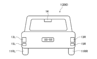
- FIG. FIG. 3 is a rear view of the vehicle 1.
- the vehicle 1 includes left and right front wheels 11FR and 11FL and left and right rear wheels 11RR and 11RL, left and right headlights 12R and 12L disposed on the front side, left and right brake lamps 13R and 13L disposed on the rear side, and a rear side.
- the brake lamp 14 is arranged at the upper center of the left side, and the left and right turn signal lamps 15R, 15L are arranged on the rear side.
- the sensor circuit 4 is arranged at the upper center inside the vehicle windshield 16 of the vehicle 1.
- the detection circuit 2 includes a position information acquisition circuit 21 and a speed information acquisition circuit 22.
- the position information acquisition circuit 21 acquires the position information of the vehicle 1, and the speed information acquisition circuit 22 acquires the position of the vehicle 1. Get speed information.
- the detection circuit 2 outputs the acquired position information and speed information of the vehicle 1 to the automatic driving control device 9.
- the map information storage circuit 3 has a read-only flash ROM that can electrically erase and rewrite data, and stores map information.
- the map information storage circuit 3 outputs corresponding map information to the automatic driving control device 9 in accordance with a request for map information from the automatic driving control device 9.
- the map information stored in the map information storage circuit 3 can be rewritten to other map information input via the wireless communication circuit 5.
- the sensor circuit 4 includes a camera, millimeter wave radar, LIDAR (Light Detection and Ranging, Laser Imaging Detection and Ranging), sonar, temperature sensor, atmospheric pressure sensor, humidity sensor, illuminance sensor, etc. Various detection results are output to the automatic operation control device 9.
- LIDAR Light Detection and Ranging, Laser Imaging Detection and Ranging
- sonar temperature sensor
- atmospheric pressure sensor atmospheric pressure sensor
- humidity sensor humidity sensor
- illuminance sensor etc.
- the wireless communication circuit 5 performs road-to-vehicle communication and receives a signal transmitted from a roadside machine (not shown). A well-known technique can be used for road-to-vehicle communication.
- the wireless communication circuit 5 outputs the received signal to the automatic operation control device 9.
- the wireless communication circuit 5 may correspond to a cellular phone communication system, WMAN (Wireless Metropolitan Area Network), etc., and may perform wireless communication with a data server, infrastructure, other vehicles, pedestrians, and the like.
- the power unit 6 includes an engine (not shown) of the vehicle 1 and a control unit that electrically controls the output of the engine, and moves the vehicle 1. During automatic operation, the output of the power unit 6 changes under the control of the automatic operation control device 9.
- the power unit 6 includes a motor (not shown) and a power unit 6 that includes both an engine and a motor. The output of the power unit 6 is also controlled by the automatic operation control device 9.
- the steering unit 7 is a steering device for arbitrarily changing the traveling direction of the vehicle 1. During automatic driving, the steering angle of the steering unit 7 changes under the control of the automatic driving control device 9.
- the braking unit 8 is a device that decelerates or stops the traveling vehicle 1. During automatic operation, the braking force of the braking unit 8 changes under the control of the automatic operation control device 9.
- the automatic operation control device 9 includes an input / output circuit 91, an output circuit 92, a memory 93, and a CPU 94.
- the input / output circuit 91 functions as an interface that electrically connects the detection circuit 2, the map information storage circuit 3, the sensor circuit 4, the wireless communication circuit 5, and the CPU 94.
- the output circuit 92 functions as an interface that electrically connects the power unit 6, the steering unit 7, the braking unit 8, and the CPU 94.
- the memory 93 includes a read-only ROM (not shown), a rewritable RAM (not shown), and a read-only flash ROM (not shown) that can electrically erase and rewrite data.
- the ROM stores a basic program for starting up the CPU 94 when the power is turned on, the RAM is used in the operation of the CPU 94, and the flash ROM stores a program for supporting the automatic driving control of the vehicle 1.
- the CPU 94 performs control related to automatic driving in cooperation with the memory 93. That is, the CPU 94 acquires position information and speed information from the detection circuit 2, acquires map information from the map information storage circuit 3, acquires various detection results detected by the sensor circuit 4, and wireless communication circuit 5. And the power unit 6, the steering unit 7 and the brake via the output circuit 92 based on the acquired position information, speed information, map information, sensor information and roadside machine (not shown) information.
- Each unit 8 is controlled to autonomously travel along a predetermined travel route.
- the vehicle 1 according to the first embodiment has a feature that can safely travel in dangerous areas such as intersections, sidewalks, and pedestrian crossings. For example, in the case where the area past the intersection is blocked, if the vehicle travels as it is, the vehicle will get stuck in the intersection, which is dangerous. However, the vehicle 1 of the first embodiment has such a danger. Control is performed so as to avoid the situation.
- a dangerous area such as an intersection, a sidewalk, and a pedestrian crossing
- a dangerous area such as an intersection, a sidewalk, and a pedestrian crossing
- an area that has passed through the dangerous area is referred to as an “exit area”.
- the exit area is an area that does not correspond to at least an intersection, a pedestrian crossing, or a sidewalk, and is an area on the roadway in the present disclosure.
- the length of the exit region is longer than the entire length of the vehicle 1 in the direction along the traveling route of the roadway and shorter than twice the entire length of the vehicle 1.
- the dangerous area corresponds to the first area
- the exit area corresponds to the second area.
- the first area and the second area correspond to the map information stored in the map information storage circuit 3.
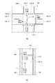
- FIGS. 5 (a), 5 (b) are diagrams showing an example of a dangerous situation when the vehicle 1 is traveling.
- FIG. 4A is a diagram illustrating a situation where the vehicle 1 is about to pass through the intersection 100.
- an intersection 100 is a dangerous area 130-1.
- the area on the roadway 120-1 adjacent to the previous pedestrian crossing 110-2 that has gone straight on the pedestrian crossing 110-1 is the exit area 140-1, and the pedestrian crossing 110-1 immediately after turning left on the pedestrian crossing 110-1
- the area on the adjacent roadway 120-2 is the exit area 140-2
- the area on the roadway 120-2 adjacent to the pedestrian crossing 110-3 that has turned right on the pedestrian crossing 110-1 is the exit area 140-3.
- the exit area 140-1 In the situation where the exit area 140-1 is blocked, if you try to proceed as it is, you will get stuck on the pedestrian crossing 110-2. In addition, in a situation where the exit area 140-2 is blocked, if you try to turn left, you will get stuck on the pedestrian crossing 110-1. In addition, if the exit area 140-3 is blocked and an attempt is made to turn right, the exit area 140-3 is stuck on the pedestrian crossing 110-3. If you get stuck on the pedestrian crossing 110-2 or on the pedestrian crossing 110-3, you may interfere with the crossing of pedestrians, or after the signal changes, you may interfere with the progress of other vehicles.
- FIG. 4 is a diagram showing a situation in which the vehicle 1 is going through the pedestrian crossing 110 on a general road.
- a pedestrian crossing 110 is a dangerous area 130-2
- an area on the roadway 120 adjacent to the pedestrian crossing 110 and far from the pedestrian crossing 110 is an exit area 140.
- the exit area 140 is blocked and the vehicle proceeds as it is, the vehicle will get stuck on the pedestrian crossing 110 as in the case of the straight traveling in FIG.
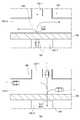
- FIG. 5 is a diagram showing a situation in which the vehicle 1 is about to exit the road 120 at the intersection 160 through the sidewalk 150 from the road 120-3.
- a sidewalk 150 is a dangerous area
- an area on the roadway 120 adjacent to the sidewalk 150 and far from the sidewalk 150 is an exit area 140.
- the exit area 140 on the roadway 120-2 is blocked, the vehicle will get stuck on the sidewalk 150, which is a dangerous area, as it proceeds.
- FIG. 5 is a diagram showing a situation in which the vehicle 1 is about to enter the roadway 120-3 from the intersection 160 through the sidewalk 150.
- a sidewalk 150 is a dangerous area
- an area on the road 120-3 adjacent to the sidewalk 150 and far from the sidewalk 150 is an exit area 140.
- the exit area 140 adjacent to the sidewalk 150 is blocked, and if it proceeds as it is, it will get stuck on the sidewalk 150.
- the automatic operation control device 9 Based on the sensor information from the sensor circuit 4, the automatic operation control device 9 sets a region corresponding to at least one of an intersection, a pedestrian crossing, and a sidewalk on the route that the vehicle 1 is scheduled to travel as a dangerous region, Further, an area adjacent to the dangerous area and far from the dangerous area is set as the exit area. Note that the route scheduled to travel ahead is a route scheduled to travel in the future, not a route traveled in the past.
- the sensor circuit 4 detects obstacles outside the vehicle such as a vehicle, a motorcycle, a person, a bicycle, and a wheelchair in both the dangerous region and the exit region. In addition, the sensor circuit 4 can detect an obstacle other than the danger area that is the first area and the exit area that is the second area.
- the automatic operation control device 9 Based on the sensor information from the sensor circuit 4, the automatic operation control device 9 performs control so as to enter the dangerous area when it is determined that there are no obstacles in both the dangerous area and the exit area. Further, when it is determined that there is no obstacle in the dangerous area and there is an obstacle in the exit area, control is performed so as not to enter the dangerous area and to stop before the dangerous area. For example, as shown in FIG. 4A, when making a right turn, the automatic operation control device 9 determines that there are no obstacles in both the dangerous area 130-1 and the outlet area 140-3. Control to enter -1.
- the control is performed so as not to enter the dangerous area 130-1 and to stop before the dangerous area 130-1. To do. As described above, even if the vehicle 1 tries to pass through the dangerous area 130-1, if the vehicle 1 cannot enter the exit area 140-3 ahead, the vehicle 1 stops before the dangerous area 130-1.
- the automatic operation control device 9 has an obstacle in the dangerous area when the sensor circuit 4 can detect an obstacle in the third area that is not on the travel route of the vehicle 1 and is adjacent to the dangerous area. If it is determined that there is no obstacle in the exit area, and that there is no obstacle toward the exit area in the third area, control is performed to enter the danger area. Also, if it is determined that there are no obstacles in the dangerous area, no obstacles in the exit area, and there are obstacles facing the exit area in the third area, the danger area is not entered before the dangerous area. Control to stop.
- the third area corresponds to the map information stored in the map information storage circuit 3 as in the first area and the second area described above.
- FIG. 6 is a diagram for explaining the automatic driving control at the intersection 160 when the sensor circuit 4 can detect an obstacle in the third region that is not on the travel route of the vehicle 1 and is adjacent to the dangerous region. is there.
- the sidewalk 150 Control to enter. If it is determined that there is no obstacle on the sidewalk 150, no obstacle in the exit area 140, and there is a vehicle 180 that is heading toward the exit area 140 in the third area 170, the sidewalk 150 does not enter the sidewalk 150. Control to stop before.
- the automatic operation control device 9 has a function of estimating the movement of the obstacle, and control using this function is also possible. For example, when the sensor circuit 4 can detect an obstacle in the third region other than the travel route of the vehicle 1 and adjacent to the dangerous region, the automatic driving control device 9 has no obstacle on the sidewalk 150, In addition, there is a vehicle 180 that has no obstacle in the exit area 140 and that faces the exit area 140 in the third area 170, and the vehicle 180 that faces the exit area 140 is in the exit area 140 from the own vehicle (vehicle 1). If it is estimated that the vehicle will arrive as soon as possible, control is performed so that the vehicle stops before the sidewalk 150 without entering the sidewalk 150.
- the automatic operation control device 9 includes the vehicle 180 that has no obstacle on the sidewalk 150, no obstacle in the exit area 140, and that faces the exit area 140 in the third area 170, and the exit.
- the vehicle 180 is controlled to enter the sidewalk 150.
- the automatic operation control device 9 has no obstacle on the sidewalk 150, the vehicle 180 in the exit area 140, and the vehicle 180 in the exit area 140 is in the exit area 140. If it is estimated that the user exits the exit area 140 before arriving at, the control is performed so as to enter the sidewalk 150.
- the sensor circuit 4 cannot detect an obstacle in the exit area 140, the sensor circuit 4 detects another vehicle 180 on the roadway 120, and the roadway 120 of the vehicle 180 is detected. If the speed along the road is larger than the predetermined speed, control is performed to enter the sidewalk 150. For example, control is performed so as to enter the sidewalk 150 at the first speed.
- control in (6) for example, in FIG. 5B, both the vehicle 1 and the vehicle 180 (not shown) travel on the roadway 120-1 (predetermined route) toward the exit area 140. It is control when it is. If the other vehicle 180 is faster than the vehicle 1, the vehicle 180 will follow the vehicle and can enter the sidewalk 150.
- the sensor circuit 4 cannot detect an obstacle in the exit area 140, the sensor circuit 4 detects another vehicle 180 on the roadway 120, and the roadway 120 of the vehicle 180 is detected. If the speed along the road is smaller than the predetermined speed, the vehicle is controlled to enter at a second speed smaller than the first speed on the sidewalk 150.
- the control in (7) is similar to the case of (6) described above.
- both the vehicle 1 and the vehicle 180 (not shown) Is traveling toward the exit area 140. If the speed of the other vehicle 180 is lower than the first speed (predetermined speed), the vehicle enters the sidewalk 150 at a second speed smaller than the first speed so as to follow.
- the automatic driving control device 9 sets the intersection, the sidewalk, and the pedestrian crossing as dangerous areas, sets the area immediately after passing through the dangerous area as the exit area, and sets the vehicle (vehicle 1) in the set exit area. ) Will not be able to enter, or when such a situation is predicted to occur soon, it will be controlled so as not to enter an intersection, sidewalk, or pedestrian crossing, so it will be stuck in a dangerous area.
- the safety of automated driving can be improved.
- the operation of the automatic driving control device 9 mounted on the vehicle 1 of the first embodiment will be described. Since the subject of the operation is the CPU 94, the subject should be the CPU 94. However, the subject is the automatic operation control device 9 because it will be described as the operation of the device itself.
- FIG. 7 is a flowchart showing basic operation steps of the automatic driving control device 9 mounted on the vehicle 1 of the first embodiment.
- the automatic operation control device 9 determines whether or not it is “stopped or traveling just before the dangerous area?” (Step S10). If the automatic operation control device 9 determines “NO” in step S10, it repeats this process until it can be determined “YES”. On the other hand, if “YES” is determined in the step S10, it is determined whether or not “a dangerous area (intersection, sidewalk or pedestrian crossing) is vacant?” (Step S11). If the automatic operation control device 9 determines “YES” in step S11, it determines whether or not “exit area is empty?” (Step S12).
- step S12 determines “YES” in step S12, it is “whether there is an obstacle (an obstacle outside the vehicle such as a vehicle, a motorcycle, a person, a bicycle, a wheelchair, etc.) heading toward the exit area?” Determination is made (step S13).
- Step S13 When the automatic operation control device 9 determines “NO” in Step S13, it recognizes that “there is an obstacle toward the exit area” (Step S14). Then, it is determined whether or not “the obstacle arrives ahead of the host vehicle” (step S15). If “NO” is determined, the vehicle enters the dangerous area, enters the exit area after passing through the dangerous area, and passes. (Step S16). After passing through the exit area, the process ends. On the other hand, if it determines with "YES” at step S15, the automatic driving
- step S13 If the automatic operation control device 9 determines “YES” in step S13, the process proceeds to step S16 as it is without performing the processing of step S15 and step S15, enters the danger area, and enters the exit area after passing the danger area. ,pass. After passing through the exit area, the process ends.
- step S11 If the automatic operation control device 9 determines “NO” in step S11, the automatic operation control device 9 does not enter the dangerous area, stops in front (step S20), and returns to step S10.
- Step S17 determines whether or not “exit area is not empty?” If it determines with “YES” at step S17, the automatic driving
- step S18 determines “NO” in step S18, it recognizes that “the vehicle is unlikely to be vacant by the time it reaches the exit area” (step S19), and enters the danger area. Without stopping (step S20), the process returns to step S10.
- step S17 If the automatic operation control device 9 determines “NO” in step S17, it recognizes that “the exit area is unknown (dead angle)” (step S21). Next, it is determined whether or not “the vehicle is traveling in a traffic flow and the exit area is expected to be vacant due to the speed of the preceding vehicle” (step S22). ”, The process proceeds to step S16, enters the dangerous area, enters the exit area after passing through the dangerous area, and passes. After passing through the exit area, the process ends. On the other hand, if the automatic operation control device 9 determines “NO” in step S22, it recognizes that “the exit area is unknown and it cannot be determined whether the vehicle is free from the position of the own vehicle” (step S23). The vehicle enters the dangerous area at a slow speed (step S24) and returns to step S10.
- the vehicle 1 has a vehicle, a motorcycle, in the danger area of the intersection, the sidewalk, and the pedestrian crossing on the route that is scheduled to travel ahead, and the exit area that is adjacent to the danger area and far from the danger area. Detects obstacles outside the vehicle such as people, bicycles, wheelchairs, etc., and if there are no obstacles in both the dangerous area and the exit area, it enters the dangerous area, there are no obstacles in the dangerous area, and the exit area When there is an obstacle, the vehicle does not enter the dangerous area and stops before the dangerous area, so that it is possible to avoid a dangerous situation where the vehicle is stuck at an intersection, a sidewalk, or a pedestrian crossing.
- obstacles outside the vehicle such as people, bicycles, wheelchairs, etc.
- the vehicle 1 when the vehicle 1 according to the first embodiment can detect an obstacle in the third area that is not on the travel route and is adjacent to the dangerous area, the dangerous area has no obstacle and the obstacle in the exit area. If there is no obstacle toward the exit area in the third area, it enters the danger area, there is no obstacle in the danger area, there is no obstacle in the exit area, and the exit area in the third area If there is an obstacle heading toward the vehicle and it is estimated that the obstacle will arrive at the exit area earlier than the own vehicle (vehicle 1), the vehicle stops before the dangerous area without entering the dangerous area. Therefore, it is possible to avoid reaching a dangerous situation with respect to obstacles in the third region other than on the travel route. On the other hand, when it is estimated that the obstacle arrives at the exit area later than the own vehicle (vehicle 1), the vehicle enters the danger area.
- the vehicle 1 of the first embodiment has no obstacle in the danger area, and the obstacle in the exit area leaves the exit area before the own vehicle (vehicle 1) arrives at the exit area.
- the vehicle since the vehicle enters the dangerous area, it does not get stuck in the dangerous area, and smooth traffic is possible.
- the sensor circuit 4 cannot detect an obstacle in the exit area, the sensor circuit 4 detects another vehicle 180 on the same roadway, and the other vehicle 180 has the same roadway. If the speed along the road is larger than the predetermined speed, the vehicle enters the danger area at the first speed. If the speed along the same roadway of the other vehicle 180 is smaller than the predetermined speed, the first speed is entered in the danger area. Since the vehicle enters at a second speed smaller than that of the vehicle, in any case, the vehicle follows the other vehicle 180, so that the vehicle does not enter into a dangerous situation such as colliding with the other vehicle 180. Traffic is possible.
- the vehicle 200 according to the second embodiment can autonomously travel along a predetermined travel route in the same manner as the vehicle 1 according to the first embodiment described above.
- the vehicle 200 according to the second embodiment can ensure safety during overtaking. Since the structure of the part which concerns on the automatic driving
- the memory 202 includes a read-only ROM (not shown), a rewritable RAM (not shown), and a read-only flash ROM (not shown) that can electrically erase and rewrite data.
- the ROM stores a basic program for starting the CPU 94 when the power is turned on, the RAM is used in the operation of the CPU 94, and the flash ROM stores a program for supporting the automatic driving control of the vehicle 200.
- the automatic driving control device 201 mounted on the vehicle 200 of the second embodiment is configured to check the oncoming lane and the presence of a temporarily stopped vehicle such as a traffic jam or a return space in order to pass the vehicle.
- the travel control function of the automatic driving control apparatus 201 includes the following four functions.
- the automatic operation control device 201 can perform overtaking traveling more safely by having the above four functions.
- FIG. 8 is a diagram for explaining overtaking control in the automatic driving control device 201 when overtaking is performed in the same lane on a one-lane road.
- FIG. 9 is a diagram for explaining the overtaking control in the automatic operation control device 201 when performing overtaking on an adjacent lane (opposite lane) on a one-lane road.
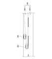
- FIG. 10 is a figure which shows the detail of the road of one side 1 lane. There are various roads such as one lane on one side, two lanes on one side, three lanes on one side, and four lanes on one side. In the present disclosure, one lane on one side is given as an example.
- the road 300 has a first lane 300-1 and a second lane 300-2 adjacent to the first lane 300-1.
- the second lane 300-2 is the opposite lane of the first lane 300-1, and has the same width.
- the boundary between the first lane 300-1 and the second lane 300-2 is a first boundary line (boundary line) 300-3.
- the first lane 300-1 has a second boundary line 300-4 opposite to the first boundary line 300-3 and indicating the boundary between the first lane 300-1 and other areas.
- the center line 300-5 of the first lane 300-1 is virtual and is usually not visible.
- the vehicle 200 travels in the first lane 300-1 along a travel route (predetermined travel route) 310, and an obstacle (for example, “another vehicle”) 400 approaches the left side in front of the vehicle 200. It has stopped.
- an obstacle for example, “another vehicle”
- the automatic driving control device 201 mounted on the vehicle 200 passes the obstacle 400 in the first lane 300-1, first, the obstacle ahead of the vehicle is obstructed by the above (Function 1) and (Function 2).
- the prediction that the vehicle is a parked vehicle is based on the fact that the speed is “0”, the brake lamps 13R, 13L and 14 are not lit, and the blinker lamps 15R and 15L are not lit. In this case, it is not necessary that all the conditions are met.
- the brake lamps 13R, 13L, and 14 may be unlit, the brake lamps 13R, 13L, and 14 are unlit, and the blinker lamps 15R, 15L are It may be the case where both non-
- the automatic driving control device 201 predicts that the obstacle 400 is a parked vehicle
- the automatic driving control device 201 moves the vehicle 200 (the own vehicle) to the right so that the vehicle 200 can pass by the obstacle 400.
- the overtaking driving is started.
- the overtaking starts and the return space is detected by the above (Function 4) and the return space can be detected, the vehicle returns to the original travel route after overtaking.
- the automatic operation control device 201 uses the above (Function 1) and (Function 2) to make the front obstacle 400 a parked vehicle. If this is predicted, the vehicle 200 (own vehicle) is brought to the right. When it is confirmed by the above (Function 3) that there is no congested vehicle line or the like beyond the obstacle 400, the vehicle exits the second lane 300-2 and starts overtaking. When the overtaking starts and the return space is detected by (Function 4) and the return space can be detected, the vehicle returns to the original lane, that is, the first lane 300-1 after overtaking.
- the above is the basic operation of the automatic operation control apparatus 201.
- the automatic operation control device 201 can also perform the following control.
- the automatic driving control apparatus 201 relates to the travel route 310 and is smaller than a predetermined speed (the speed of the vehicle 200) while the vehicle 200 travels on the travel route 310 of the first lane 300-1.
- a predetermined speed the speed of the vehicle 200
- the vehicle travels closer to the first boundary line 300-3 between the first lane 300-1 and the second lane 300-2 from the travel route 310.
- the sensor circuit 4 is controlled to detect the second obstacle (not shown) in the traveling direction.
- the speed smaller than the predetermined speed (the speed of the vehicle 200) includes stopping.
- the automatic operation control device 201 is a first vehicle that travels at a speed that is related to the travel path 310 and that is smaller than a predetermined speed while the vehicle 200 travels on the travel path 310 of the first lane 300-1.
- control is performed so as to approach the first boundary line 300-3 from the travel route 310 and travel without exceeding the first boundary line 300-3.
- the automatic driving control device 201 is a first vehicle that travels at a speed that is related to the travel path 310 and that is smaller than a predetermined speed while the vehicle 200 travels on the travel path 310 of the first lane 300-1.
- a predetermined speed that is related to the travel path 310 and that is smaller than a predetermined speed while the vehicle 200 travels on the travel path 310 of the first lane 300-1.
- the automatic operation control apparatus 201 is a first unit that moves in relation to the travel route 310 and travels at a speed smaller than a predetermined speed while the vehicle 200 travels on the travel route 310 of the first lane 300-1.
- the vehicle travels Control is performed so that the vehicle travels closer to the first boundary line 300-3 from the route 310.
- the automatic operation control apparatus 201 is a first unit that moves in relation to the travel route 310 and travels at a speed smaller than a predetermined speed while the vehicle 200 travels on the travel route 310 of the first lane 300-1.
- the first boundary line 300-3 and the second boundary line When there is an obstacle (not shown) and the first obstacle moving on the first boundary line 300-3 side at a speed smaller than a predetermined speed is the first boundary line 300-3 and the second boundary line.
- control is performed so that the vehicle travels closer to the first boundary line 300-3 than the travel route 310.
- the automatic driving control device 201 is a first vehicle that travels at a speed that is related to the travel route 310 and that is smaller than a predetermined speed while the vehicle 200 travels on the travel route 310 of the first lane 300-1.
- a predetermined speed When there is an obstacle (not shown) and there is no predetermined facility within a predetermined distance ahead, the first boundary line between the first lane 300-1 and the second lane 300-2 from the travel route 310 The vehicle travels close to 300-3, and the vehicle 200 travels along the travel route (predetermined travel route) 310 of the first lane 300-1, and is associated with the travel route 310 and smaller than the predetermined speed.
- the vehicle travels on the travel route 310 and stops before the first obstacle.
- the predetermined facility is at least one of an intersection, a pedestrian crossing, and an entrance / exit of a commercial facility.
- the automatic driving control device 201 After the vehicle 200 is brought to the first boundary line 300-3, the automatic driving control device 201 tries to detect the second obstacle (not shown) in the traveling direction by the sensor circuit 4, and the first obstacle ( When at least the second obstacle is detected in front of (not shown), control is performed so as to stop before the first obstacle.
- the automatic driving control device 201 does not detect at least the second obstacle (not shown) in front of the first obstacle (not shown), the automatic driving control device 201 at least part of the vehicle 200 is the first boundary line 300- Control is performed so that the vehicle travels beside the first obstacle while exceeding 3.
- the automatic driving control device 201 When the automatic driving control device 201 does not detect at least the second obstacle (not shown) in front of the first obstacle (not shown), at least a part of the vehicle 200 is the first boundary line 300- When the sensor circuit 4 detects that a predetermined space is vacant on the first lane 300-1 while traveling beside the first obstacle in a state exceeding 3, the travel route (predetermined The travel route is controlled to return to 310.
- the operation of the automatic driving control device 201 mounted on the vehicle 200 of the second embodiment will be described. Since the subject of the operation is the CPU 94, the subject should be the CPU 94. However, the subject is the automatic operation control device 201 because it will be described as the operation of the device itself.
- FIG. 11 is a flowchart showing the basic operation steps of the automatic driving control apparatus 201 mounted on the vehicle 200 of the second embodiment.
- the automatic driving control apparatus 201 determines whether or not “Confirm safety of oncoming lane?” (Step S30). If the automatic operation control apparatus 201 determines “NO” in step S30, it recognizes that “no overtaking” (step S40), and returns to step S30. On the other hand, if “YES” is determined in step S30, it is determined whether or not “the parked vehicle is“ stopped, speed “0”, brake light not lit, blinker lamp not lit? ”(Step S31). ).
- step S31 If the automatic operation control device 201 determines “NO” in step S31, it recognizes that “no overtaking” (step S40), and returns to step S30. On the other hand, if “YES” is determined in the step S31, it is determined whether or not "a parked vehicle is parked on the left side of the road” (step S32).
- step S32 determines “NO” in step S32, it recognizes that “no overtaking” (step S40), and returns to step S30.
- step S33 it is determined whether or not “no intersection, pedestrian crossing, and entrance / exit of the commercial facility exist within the forward ⁇ m” (step S33).
- the forward ⁇ m is, for example, 50 m. Alternatively, it may be 100 m, or 40 m, 30 m, 20 m, or 10 m. If the automatic operation control apparatus 201 determines “NO” in step S33, it recognizes that “no overtaking” (step S40), and returns to step S30.
- step S34 “the vehicle (the vehicle 200) is brought to the right of the road” is controlled (step S34).
- the automatic driving control apparatus 201 determines whether or not it is possible to confirm that there is no traffic jam line or the like beyond the parked vehicle (step S35). If the automatic operation control apparatus 201 determines “NO” in step S35, it recognizes that “no overtaking” (step S40), and returns to step S30. On the other hand, if “YES” is determined in the step S35, a control “going to the opposite lane” is performed (step S36).
- step S37 determines whether “return space has been detected” (step S37). If the automatic operation control device 201 determines “NO” in step S37, it performs control of “straight running” (step S39), and returns to step S37. On the other hand, if “YES” is determined in the step S37, a control of “returning to the own lane” is performed (step S38). Then, when the vehicle returns to the own lane, this processing is finished. Note that step S33 described above is not essential and may be omitted.
- the vehicle 200 approaches the sensor circuit after approaching the first boundary line 300-3 between the first lane 300-1 and the second lane 300-2 of the road 300 in order to pass. Since 4 tries to detect the second obstacle in the traveling direction, it is possible to confirm the presence or absence of a return space to the host vehicle route at the overtaking destination, so that safety during overtaking can be ensured.
- the vehicle and the automatic driving control device of the present disclosure are useful for vehicles such as automobiles and trucks.
Landscapes
- Engineering & Computer Science (AREA)
- Transportation (AREA)
- Mechanical Engineering (AREA)
- Automation & Control Theory (AREA)
- Chemical & Material Sciences (AREA)
- Combustion & Propulsion (AREA)
- Physics & Mathematics (AREA)
- General Physics & Mathematics (AREA)
- Human Computer Interaction (AREA)
- Traffic Control Systems (AREA)
- Control Of Driving Devices And Active Controlling Of Vehicle (AREA)
Abstract
外部の障害物を検出可能なセンサー回路(4)を備え、車両(1)は、少なくとも第1車線と、第1車線と隣接する第2車線とを有する道路において第1車線の所定の走行経路を走行している間に、センサー回路(4)からのセンサー情報により、所定の走行経路に関連し、かつ所定の速度より小さい速度で移動する第1障害物がある場合、所定の走行経路より、第1車線と第2車線との境界線に寄って走行し、境界線に寄った後に、センサー回路(4)が進行方向の第2障害物の検出を行う。
Description
本開示は、所定の走行経路を自律的に走行可能な車両及び該車両に用いられる自動運転制御装置に関する。
近年、所定の走行経路を自律的に走行可能な車両の開発が進められている。自動運転に関する技術として、例えば特許文献1に記載されたような、追い越しにおける安全性を向上させたものがある。
特許文献1には、追い越し対象車両と追い越し車線並走車両とを監視し、自車両が追い越し対象車両の追い越し制御を開始した場合と追い越し制御のための車線変更を行った場合の少なくとも一方の場合に、自車両の前方を走行する追い越し車線並走車両の位置が、自車両が追い越し対象車両を追い越すための車線変更先の近傍、または、所定距離内の前方となると判定できる領域(追い越し車線上の現在の自車両位置の前方から後方にかけての予め設定する領域)内に存在することが予想される場合、追い越し走行を中止する方向に制御し、追い越し対象車両を追い越すために自車両が車線変更を行って自車両の前方に追い越し車線並走車両が存在し、かつ、追い越し車線並走車両が元存在した車線に予め設定するスペースを検出した場合には、車線変更制御を実施する技術が開示されている。
本開示は、追い越し走行時における安全性を確保することができる車両及び自動運転制御装置を提供することを目的とする。
本開示の車両は、電気的に制御可能な動力部と、電気的に制御可能な操舵部と、電気的に制御可能な制動部と、外部の障害物を検出可能なセンサー回路と、を備え、前記動力部、前記操舵部、及び前記制動部の内、少なくとも1つに対して電気的に制御を加えて、所定の走行経路を自律的に走行可能な車両であって、少なくとも第1車線と、前記第1車線と隣接する第2車線とを有する道路において前記第1車線の前記所定の走行経路を走行している間に、前記所定の走行経路に関連し、かつ所定の速度より小さい速度で移動する第1障害物がある場合、前記所定の走行経路より、前記第1車線と前記第2車線との境界線に寄って走行し、前記境界線に寄った後に、前記センサー回路は進行方向の第2障害物を検出しようとする。
本開示によれば、追い越しを行うため第1車線と第2車線との境界線に寄った後に、センサー回路が進行方向の第2障害物を検出しようとする。
したがって、追い越した先で自車経路への復帰スペースの有無を確認することができるので、追い越し走行時における安全性を確保することができる。
したがって、追い越した先で自車経路への復帰スペースの有無を確認することができるので、追い越し走行時における安全性を確保することができる。
本開示の自動運転制御装置は、電気的に制御可能な動力部と、電気的に制御可能な操舵部と、電気的に制御可能な制動部と、外部の障害物を検出可能なセンサー回路と、を備え、前記動力部、前記操舵部、及び前記制動部の内、少なくとも1つに対して電気的に制御を加えて、所定の走行経路を自律的に走行可能な車両に搭載可能な自動運転制御装置であって、少なくとも第1車線と、前記第1車線と隣接する第2車線とを有する道路において前記第1車線の前記所定の走行経路を走行している間に、前記所定の走行経路に関連し、かつ所定の速度より小さい速度で移動する第1障害物がある場合、前記所定の走行経路より、前記第1車線と前記第2車線との境界線に寄って走行するように制御し、前記境界線に寄った後に、前記センサー回路は進行方向の第2障害物を検出しようとするように制御する。
本開示によれば、追い越しを行うため第1車線と第2車線との境界線に寄るように制御して、該境界線に寄った後に、センサー回路が進行方向の第2障害物を検出しようとするように制御する。
したがって、追い越した先で自車経路への復帰スペースの有無を確認することができるので、追い越し走行時における安全性を確保することができる。
したがって、追い越した先で自車経路への復帰スペースの有無を確認することができるので、追い越し走行時における安全性を確保することができる。
以下、適宜図面を参照しながら、本開示に係る車両及び自動運転制御装置を具体的に開示した実施形態(以下、「本実施形態」という)を詳細に説明する。但し、必要以上に詳細な説明は省略する場合がある。例えば、既によく知られた事項の詳細説明や実質的に同一の構成に対する重複説明を省略する場合がある。これは、以下の説明が不必要に冗長になるのを避け、当業者の理解を容易にするためである。なお、添付図面および以下の説明は、当業者が本開示を十分に理解するために提供されるのであって、これらにより特許請求の範囲に記載の主題を限定することは意図されていない。
以下、本開示を実施するための好適な本実施形態について、図面を参照して詳細に説明する。
(第1実施形態)
以下、図1を参照して、第1実施形態の車両1について説明する。図1は、第1実施形態の車両1の自動運転に係る部分の構成を示すブロック図である。同図において、車両1は、車両1の位置と速度を検出する検出回路2と、地図情報を記憶した地図情報記憶回路3と、車両1の外部に存在する障害物を検出するセンサー回路4と、外部と無線通信可能な無線通信回路5と、電気的に制御可能な動力部6と、電気的に制御可能な操舵部7と、電気的に制御可能な制動部8と、動力部6、操舵部7及び制動部8に対して電気的に制御を加えて、車両1を所定の走行経路を自律的に走行させる自動運転制御装置9と、を備える。
以下、図1を参照して、第1実施形態の車両1について説明する。図1は、第1実施形態の車両1の自動運転に係る部分の構成を示すブロック図である。同図において、車両1は、車両1の位置と速度を検出する検出回路2と、地図情報を記憶した地図情報記憶回路3と、車両1の外部に存在する障害物を検出するセンサー回路4と、外部と無線通信可能な無線通信回路5と、電気的に制御可能な動力部6と、電気的に制御可能な操舵部7と、電気的に制御可能な制動部8と、動力部6、操舵部7及び制動部8に対して電気的に制御を加えて、車両1を所定の走行経路を自律的に走行させる自動運転制御装置9と、を備える。
図2の(a)は、車両1の平面図、図2の(b)は車両1の側面図である。また、図3は、車両1の背面図である。車両1は、左右前輪11FR,11FL及び左右後輪11RR,11RLと、フロント側に配置された左右のヘッドライト12R,12Lと、リア側に配置された左右のブレーキランプ13R,13Lと、リア側の中央上部に配置されたブレーキランプ14と、リア側に配置された左右のウインカーランプ15R,15Lと、を有している。センサー回路4は、車両1のフロントガラス16の車内側の上部中央に配置される。
図1に戻り、検出回路2は、位置情報取得回路21と、速度情報取得回路22とを備え、位置情報取得回路21で車両1の位置情報を取得し、速度情報取得回路22で車両1の速度情報を取得する。検出回路2は、取得した車両1の位置情報と速度情報を自動運転制御装置9に出力する。地図情報記憶回路3は、電気的にデータの消去や書き換えが可能な読み出し専用のフラッシュROMを有し、地図情報を記憶する。地図情報記憶回路3は、自動運転制御装置9からの地図情報の要求に従い、該当する地図情報を自動運転制御装置9に出力する。地図情報記憶回路3に記憶された地図情報は、無線通信回路5を介して入力される他の地図情報に書き換え可能である。センサー回路4は、カメラ、ミリ波レーダ、LIDAR(Light Detection and Ranging、Laser Imaging Detection and Ranging)、ソナー、気温センサー、気圧センサー、湿度センサー、照度センサー等を有しており、
各種検出結果を自動運転制御装置9に出力する。
各種検出結果を自動運転制御装置9に出力する。
無線通信回路5は、路車間通信を行い、路側機(図示略)から送信される信号を受信する。路車間通信については公知の技術を使用することができる。無線通信回路5は、受信した信号を自動運転制御装置9に出力する。なお、無線通信回路5は、携帯電話通信システム、WMAN(Wireless Metropolitan Area Network)等に対応してもよく、データサーバ、インフラ、他車両、歩行者等と無線通信を行うようにしてもよい。
動力部6は、車両1のエンジン(図示略)と、該エンジンの出力を電気的に制御する制御ユニットを含み、車両1を動かす。自動運転時には、動力部6の出力が自動運転制御装置9の制御により変化する。なお、動力部6にはモータ(図示略)を有するものや、エンジンとモータの両方を有するものもあり、これらにおいても自動運転制御装置9によって出力が制御される。操舵部7は、車両1の進行方向を任意に変えるための舵取り装置である。自動運転時には、操舵部7の操舵角が自動運転制御装置9の制御により変化する。制動部8は、走行中の車両1を減速させたり、停止させたりする装置である。自動運転時には、制動部8の制動力が自動運転制御装置9の制御により変化する。
自動運転制御装置9は、入出力回路91と、出力回路92と、メモリ93と、CPU94と、を備える。入出力回路91は、検出回路2、地図情報記憶回路3、センサー回路4及び無線通信回路5とCPU94とを電気的に接続するインタフェースとして機能する。出力回路92は、動力部6、操舵部7及び制動部8とCPU94とを電気的に接続するインタフェースとして機能する。メモリ93は、データ読み出し専用のROM(図示略)と、データの書き換えが可能なRAM(図示略)と、電気的にデータの消去や書き換えが可能な読み出し専用のフラッシュROM(図示略)とを有し、ROMは電源投入時にCPU94を起動させるための基本プログラムを記憶し、RAMはCPU94の動作において使用され、フラッシュROMは車両1の自動運転制御を支援するプログラムを記憶する。
CPU94は、メモリ93と協働して自動運転に係る制御を行う。即ち、CPU94は、検出回路2から位置情報及び速度情報を取得し、また地図情報記憶回路3から地図情報を取得し、さらにセンサー回路4で検出された各種検出結果を取得するとともに無線通信回路5で受信された信号を取得し、取得した位置情報、速度情報、地図情報、センサー情報及び路側機(図示略)の情報を基に、出力回路92を介して動力部6、操舵部7及び制動部8それぞれを制御して、所定の走行経路を自律的に走行させる。特に、第1実施形態の車両1においては、交差点、歩道及び横断歩道のような危険を伴う領域を安全に走行できる特徴を有している。例えば、交差点を通過した先の領域が塞がっているような場合、そのまま走行してしまうと交差点内で立ち往生することになり危険な状況になるが、第1実施形態の車両1ではそのような危険な状況に至らないように回避する制御が行われる。
本開示では、交差点、歩道及び横断歩道のような危険を伴う領域を“危険領域”と呼び、危険領域を通過した先の領域を“出口領域”と呼ぶ。出口領域は、少なくとも交差点、横断歩道、歩道のいずれにも対応しない領域であり、本開示では、車道上にある領域としている。また、本開示では、出口領域の長さを、車道の走行経路に沿った方向について車両1の全長よりも長く、車両1の全長の2倍より短い長さとしている。なお、危険領域は、第1領域に対応し、出口領域は、第2領域に対応する。また、第1領域及び第2領域は、地図情報記憶回路3に記憶された地図情報に対応している。
図4(a),(b)及び図5(a),(b)は、車両1の走行における危険な状況の一例を示す図である。図4の(a)は、車両1が交差点100を通過しようとする状況を示す図である。同図において、交差点100が危険領域130-1である。また、横断歩道110-1を直進した先の横断歩道110-2に隣接する車道120-1上の領域が出口領域140-1、横断歩道110-1を左折した直後の横断歩道110-1に隣接する車道120-2上の領域が出口領域140-2、横断歩道110-1を右折した先の横断歩道110-3に隣接する車道120-2上の領域が出口領域140-3である。
出口領域140-1が塞がってしまった状況で、そのまま進行しようとすると横断歩道110-2上で立ち往生することになる。また、出口領域140-2が塞がってしまった状況で、左折しようとすると横断歩道110-1上で立ち往生することになる。また、出口領域140-3が塞がってしまった状況で、右折しようとすると横断歩道110-3上で立ち往生することになる。横断歩道110-2上や横断歩道110-3上で立ち往生してしまうと、歩行者の横断を妨害したり、信号が変わった後に他の車両の進行を妨害したりしてしまう。
図4の(b)は、車両1が一般道で横断歩道110を通過しようとしている状況を示す図である。同図において、横断歩道110が危険領域130-2であり、横断歩道110に隣接し、横断歩道110より遠い車道120上の領域が出口領域140となる。この例の場合、出口領域140が塞がってしまった状況で、そのまま進行すると、図4の(a)の直進の場合と同様に横断歩道110上で立ち往生してしまうことになる。なお、図4の(b)に示す例では、車道120の両側に歩道150がある。
図5の(a)は、車両1が車道120-3から歩道150を通過して交差点160の車道120に出ようとしている状況を示す図である。同図において、歩道150が危険領域であり、歩道150に隣接し、歩道150より遠い車道120上の領域が出口領域140となる。この例の場合、車道120-2上の出口領域140が塞がってしまった状況で、そのまま進行すると危険領域である歩道150上で立ち往生してしまうことになる。
図5の(b)は、車両1が交差点160から歩道150を通過して車道120-3に入ろうとしている状況を示す図である。同図において、歩道150が危険領域であり、歩道150に隣接し、歩道150より遠い車道120-3上の領域が出口領域140となる。この例の場合、歩道150に隣接する出口領域140が塞がってしまった状況で、そのまま進行すると歩道150上で立ち往生してしまうことになる。
次に、自動運転制御装置9の制御の詳細について説明する。
自動運転制御装置9は、センサー回路4からのセンサー情報を基に、車両1が、この先走行予定の経路上における交差点、横断歩道及び歩道の少なくとも1つに対応する領域を危険領域として設定し、また危険領域に隣接し、該危険領域より遠い領域を出口領域として設定する。なお、この先走行予定の経路とは、未来に走行予定の経路であり、過去に走行した経路ではない。センサー回路4は、危険領域と出口領域の両方の領域において、車両、バイク、人、自転車、車椅子等の車外の障害物を検出する。なお、センサー回路4は、第1領域である危険領域と第2領域である出口領域以外でも障害物の検出が可能である。
自動運転制御装置9は、センサー回路4からのセンサー情報を基に、車両1が、この先走行予定の経路上における交差点、横断歩道及び歩道の少なくとも1つに対応する領域を危険領域として設定し、また危険領域に隣接し、該危険領域より遠い領域を出口領域として設定する。なお、この先走行予定の経路とは、未来に走行予定の経路であり、過去に走行した経路ではない。センサー回路4は、危険領域と出口領域の両方の領域において、車両、バイク、人、自転車、車椅子等の車外の障害物を検出する。なお、センサー回路4は、第1領域である危険領域と第2領域である出口領域以外でも障害物の検出が可能である。
(1)自動運転制御装置9は、センサー回路4からのセンサー情報を基に、危険領域と出口領域の両方の領域に障害物が無いと判断すると、危険領域に進入するように制御する。また、危険領域に障害物が無く、出口領域に障害物が有ると判断すると、危険領域に進入せず、危険領域の手前で停止するように制御する。例えば図4の(a)に示すように、右折する場合、自動運転制御装置9は、危険領域130-1と出口領域140-3の両方の領域に障害物が無いと判断すると、危険領域130-1に進入するように制御する。また、危険領域130-1に障害物が無く、出口領域140-3に障害物が有ると判断すると、危険領域130-1に進入せず、危険領域130-1の手前で停止するように制御する。このように、車両1が危険領域130-1を通過しようとしても、その先の出口領域140-3に進入不可な状況であれば、危険領域130-1の手前で停止する。
(2)また、自動運転制御装置9は、センサー回路4が、車両1の走行経路上以外であって危険領域に隣接する第3領域の障害物を検出可能である場合、危険領域に障害物が無く、かつ出口領域に障害物が無く、かつ第3領域において出口領域に向かっている障害物が無いと判断すると、危険領域に進入するように制御する。また、危険領域に障害物が無く、かつ出口領域に障害物が無く、かつ第3領域において出口領域に向かっている障害物が有ると判断すると、危険領域に進入せずに危険領域の手前で停止するように制御する。なお、第3領域は、上述した第1領域及び第2領域と同様に地図情報記憶回路3に記憶された地図情報に対応している。
図6は、センサー回路4が、車両1の走行経路上以外であって危険領域に隣接する第3領域の障害物を検出可能である場合の交差点160における自動運転制御を説明するための図である。同図において、危険領域である歩道150に障害物が無く、かつ出口領域140に障害物が無く、かつ第3領域170において出口領域140に向かっている車両180が無いと判断すると、歩道150に進入するように制御する。また、歩道150に障害物が無く、かつ出口領域140に障害物が無く、かつ第3領域170において出口領域140に向かっている車両180が有ると判断すると、歩道150に進入せずに歩道150の手前で停止するように制御する。
(3)また、自動運転制御装置9は、障害物の動きを推定する機能を有しており、この機能を用いた制御も可能である。例えば、センサー回路4が、車両1の走行経路上以外であって危険領域に隣接する第3領域の障害物を検出可能である場合、自動運転制御装置9は、歩道150に障害物が無く、かつ出口領域140に障害物が無く、かつ第3領域170において出口領域140に向かっている車両180が有り、かつ出口領域140に向かっている車両180が出口領域140に自車(車両1)よりも早く到着することを推定すると、歩道150に進入せずに歩道150の手前で停止するように制御する。
(4)また、自動運転制御装置9は、歩道150に障害物が無く、かつ出口領域140に障害物が無く、かつ第3領域170において出口領域140に向かっている車両180が有り、かつ出口領域140に向かっている車両180が出口領域140に自車(車両1)よりも遅く到着することを推定すると、歩道150に進入するように制御する。
(5)また、自動運転制御装置9は、歩道150に障害物が無く、かつ出口領域140に車両180が有り、かつ出口領域140に有る車両180が、自車(車両1)が出口領域140に到着する前に出口領域140から出て行くことを推定すると、歩道150に進入するように制御する。
(6)また、自動運転制御装置9は、センサー回路4が出口領域140の障害物を検出できず、かつセンサー回路4が車道120上に他の車両180を検出し、該車両180の車道120に沿った速度が、所定の速度より大きい場合、歩道150に進入するように制御する。例えば第1の速度で歩道150に進入するように制御する。この(6)における制御は、例えば、図5の(b)において、車両1と車両180(図示していない)が共に車道120-1(所定の経路)上を出口領域140に向かって走行している場合の制御である。他の車両180が車両1より速度が速ければ、その後をついて行くことになるので、歩道150に進入することができる。
(7)また、自動運転制御装置9は、センサー回路4が出口領域140の障害物を検出できず、かつセンサー回路4が車道120上に他の車両180を検出し、該車両180の車道120に沿った速度が、所定の速度より小さい場合、歩道150における第1の速度より小さい第2の速度で進入するように制御する。この(7)における制御は、上述した(6)の場合と同様に、図5の(b)において、車両1と車両180(図示していない)が共に車道120-1(所定の経路)上を出口領域140に向かって走行している場合である。他の車両180の速度が、第1の速度(所定の速度)より小さければ、その後をついて行くように、第1の速度より小さい第2の速度で歩道150に進入する。
このように、自動運転制御装置9は、交差点、歩道及び横断歩道を危険領域として設定し、更に危険領域を通過した直後の領域を出口領域として設定し、設定した出口領域に自車(車両1)が進入不可な状況や、そのような状況が直ぐに発生することが予測される場合に、交差点、歩道、横断歩道への進入を行わないように制御するので、危険領域で立ち往生してしまうことがなく、自動運転の安全性向上が図れる。
次に、第1実施形態の車両1に搭載された自動運転制御装置9の動作について説明する。なお、動作の主体はCPU94であるので、主語をCPU94とすべきであるが、装置そのものの動作として説明することにするので、主語を自動運転制御装置9とする。
図7は、第1実施形態の車両1に搭載された自動運転制御装置9の基本的な動作ステップを示すフローチャートである。同図において、自動運転制御装置9は、「危険領域の直前で停止又は走行している?」かどうか判定する(ステップS10)。自動運転制御装置9は、ステップS10で「NO」と判定すると、「YES」と判定できるまで本処理を繰り返す。これに対し、ステップS10で「YES」と判定すると、「危険領域(交差点、歩道又は横断歩道)が空いている?」かどうか判定する(ステップS11)。自動運転制御装置9は、ステップS11で「YES」と判定すると、「出口領域が空いている?」かどうか判定する(ステップS12)。自動運転制御装置9は、ステップS12で「YES」と判定すると、「出口領域に向かっている障害物(車両、バイク、人、自転車、車椅子等の車外の障害物)が存在しない?」かどうか判定する(ステップS13)。
自動運転制御装置9は、ステップS13で「NO」と判定すると、「出口領域に向かっている障害物が存在する」ことを認識する(ステップS14)。そして、「障害物が自車より先に到着する?」かどうか判定し(ステップS15)、「NO」と判定すると、危険領域へ進入し、危険領域通過後、出口領域へ進入し、通過する(ステップS16)。出口領域を通過した後、本処理を終える。これに対し、自動運転制御装置9は、ステップS15で「YES」と判定すると、危険領域へ進入せず、手前で停止し(ステップS20)、ステップS10に戻る。
自動運転制御装置9は、ステップS13で「YES」と判定すると、ステップS15及びステップS15の処理を行わず、そのままステップS16に進み、危険領域へ進入し、危険領域通過後、出口領域へ進入し、通過する。出口領域を通過した後、本処理を終える。
自動運転制御装置9は、ステップS11で「NO」と判定すると、危険領域へ進入せず、手前で停止し(ステップS20)、ステップS10に戻る。
自動運転制御装置9は、ステップS12で「NO」と判定すると、「出口領域が空いていない?」かどうか判定する(ステップS17)。自動運転制御装置9は、ステップS17で「YES」と判定すると、「自車が出口領域に到着するまでに空きそう?」かどうか判定する(ステップS18)。自動運転制御装置9は、ステップS18で「YES」と判定すると、ステップS16に進み、危険領域へ進入し、危険領域通過後、出口領域へ進入し、通過する。出口領域を通過した後、本処理を終える。これに対し、自動運転制御装置9は、ステップS18で「NO」と判定すると、「自車が出口領域に到着するまでに空きそうにない」ことを認識し(ステップS19)、危険領域へ進入せず手前で停止し(ステップS20)、ステップS10に戻る。
自動運転制御装置9は、ステップS17で「NO」と判定すると、「出口領域が不明(死角)」であることを認識する(ステップS21)。次いで、「自車が交通流に乗って走行しており、前走車の速度により出口領域が空らかに空いていることが予想される?」かどうか判定し(ステップS22)、「YES」と判定すると、ステップS16に進み、危険領域へ進入し、危険領域通過後、出口領域へ進入し、通過する。出口領域を通過した後、本処理を終える。これに対し、自動運転制御装置9は、ステップS22で「NO」と判定すると、「出口領域が不明で、自車の位置から空いているか判断することができない」ことを認識し(ステップS23)、危険領域へ徐行速度で進入し(ステップS24)、ステップS10に戻る。
以上のように、第1実施形態の車両1は、この先走行予定の経路上における交差点、歩道及び横断歩道の危険領域と、危険領域に隣接し、危険領域より遠い出口領域とにおいて、車両、バイク、人、自転車、車椅子等の車外の障害物の検出を行い、危険領域と出口領域の両方の領域に障害物が無い場合、危険領域に進入し、危険領域に障害物が無く、出口領域に障害物が有る場合、危険領域に進入せず、危険領域の手前で停止するので、交差点、歩道及び横断歩道で立ち往生してしまうような危険な状況に至るのを回避することができる。
また、第1実施形態の車両1は、走行経路上以外であって危険領域に隣接する第3領域の障害物を検出可能である場合、危険領域に障害物が無く、かつ出口領域に障害物が無く、かつ第3領域において出口領域に向かっている障害物が無い場合、危険領域に進入し、危険領域に障害物が無く、かつ出口領域に障害物が無く、かつ第3領域において出口領域に向かっている障害物が有って、該障害物が自車(車両1)よりも早く出口領域に到着することが推定される場合、危険領域に進入せずに危険領域の手前で停止するので、走行経路上以外の第3領域の障害物に対し、危険な状況に至るのを回避することができる。一方、障害物が自車(車両1)よりも遅く出口領域に到着することが推定される場合は、危険領域に進入する。
また、第1実施形態の車両1は、危険領域に障害物が無く、かつ出口領域に有る障害物が、自車(車両1)が出口領域に到着する前に出口領域から出て行くことを推定した場合、危険領域に進入するので、危険領域で立ち往生してしまうことがなく、スムーズな通行が可能となる。
また、第1実施形態の車両1は、センサー回路4が出口領域の障害物を検出できず、かつセンサー回路4が同一車道上に他の車両180を検出し、他の車両180の同一車道に沿った速度が、所定の速度より大きい場合、危険領域に第1の速度で進入し、他の車両180の同一車道に沿った速度が、所定の速度より小さい場合、危険領域に第1の速度よりも小さい第2の速度で進入するので、いずれの場合においても他の車両180の後をついて行くことになるため、他の車両180と衝突してしまうような危険な状況になることなく、スムーズな通行が可能となる。
(第2実施形態)
第2実施形態の車両200は、前述した第1実施形態の車両1と同様に、所定の走行経路を自律的に走行できるものである。特に、第2実施形態の車両200は、追い越し走行時における安全性を確保できるものである。第2実施形態の車両200の自動運転に係る部分の構成は、前述した第1実施形態の車両1と同様であるので、図1を援用する。但し、自動運転制御装置の機能の一部に違いがあるので、自動運転制御装置と、該自動運転制御装置を構成するメモリには異なる符号を付ける。この場合、自動運転制御装置に「201」を付け、自動運転制御装置201を構成するメモリに「202」を付ける。
第2実施形態の車両200は、前述した第1実施形態の車両1と同様に、所定の走行経路を自律的に走行できるものである。特に、第2実施形態の車両200は、追い越し走行時における安全性を確保できるものである。第2実施形態の車両200の自動運転に係る部分の構成は、前述した第1実施形態の車両1と同様であるので、図1を援用する。但し、自動運転制御装置の機能の一部に違いがあるので、自動運転制御装置と、該自動運転制御装置を構成するメモリには異なる符号を付ける。この場合、自動運転制御装置に「201」を付け、自動運転制御装置201を構成するメモリに「202」を付ける。
メモリ202は、データ読み出し専用のROM(図示略)と、データの書き換えが可能なRAM(図示略)と、電気的にデータの消去や書き換えが可能な読み出し専用のフラッシュROM(図示略)とを有し、ROMは電源投入時にCPU94を起動させるための基本プログラムを記憶し、RAMはCPU94の動作において使用され、フラッシュROMは車両200の自動運転制御を支援するプログラムを記憶する。
例えば、片側1車線の車道で前方の車両(走行中、停止中に関わらず前方に存在する車両)を追い越す場合、車両200の一部分が隣接する車線からはみ出す可能性があるものの、同一車線内で行える場合もあれば、隣接する車線(対向車線)に出て行う場合もある。後者の場合は特に対向車線に出ることから、対向車に対して十分注意を払う必要がある。第2実施形態の車両200に搭載された自動運転制御装置201は、追い越し走行するために、対向車線の確認と、渋滞等の一時停止車や復帰スペースの有無を確認するようにしている。これらの確認を行うために、自動運転制御装置201の走行制御機能には以下に示す4つの機能が含まれる。
(機能1)センサー回路4のカメラ(図示略)からの撮像データを基に、他の車両のブレーキランプ13R,13L及び14(図3参照)の点灯の有無確認(ブレーキランプ13R,13L及び14の点灯は一時停止車である)及び他の車両のウインカーランプ15R,15Lの点灯の有無確認
(機能2)道路左側に停車していることによる右側スペースの大きさによる駐車車両の予測
(機能3)交差点や横断歩道付近、信号機付近等の地図から渋滞車予測
(機能4)追い越し対象車両の手前で右寄せ走行して追い越し対象車両の向こう側の復帰スペースの検知
(機能2)道路左側に停車していることによる右側スペースの大きさによる駐車車両の予測
(機能3)交差点や横断歩道付近、信号機付近等の地図から渋滞車予測
(機能4)追い越し対象車両の手前で右寄せ走行して追い越し対象車両の向こう側の復帰スペースの検知
自動運転制御装置201は、上記4つの機能を有することで、より安全に追い越し走行を行うことができる。図8は、片側1車線の道路において同一車線内で追い越しを行うときの自動運転制御装置201における追い越し制御を説明するための図である。また、図9は、片側1車線の道路において、隣接する車線(対向車線)に出て追い越しを行うときの自動運転制御装置201における追い越し制御を説明するための図である。また、図10は、片側1車線の道路の詳細を示す図である。なお、道路は、片側1車線のみならず、片側2車線、片側3車線、片側4車線など様々であるが、本開示では片側1車線を例に挙げている。
図10に示すように、道路300は、第1車線300-1と、第1車線300-1と隣接する第2車線300-2とを有する。第2車線300-2は、第1車線300-1の対向車線であり、同じ幅である。また、第1車線300-1と第2車線300-2との境が第1境界線(境界線)300-3である。また、第1車線300-1は、第1境界線300-3と反対にあって、第1車線300-1とその他の領域の境界を示す第2境界線300-4を有している。また、第1車線300-1の中央線300-5は、仮想的なものであり、通常は見えない。
車両200は、第1車線300-1内を走行経路(所定の走行経路)310で走行しており、車両200の前方には障害物(例えば、“他の車両”)400が左側に寄って停止している。このような状況において、車両200に搭載された自動運転制御装置201は、第1車線300-1内で障害物400を追い越す場合、まず上記(機能1),(機能2)により前方の障害物400が駐車車両であることを予測する。駐車車両であることの予測は、速度が“0”、ブレーキランプ13R,13L及び14が無点灯、ウインカーランプ15R,15Lが無点灯に基づく。この場合、全ての条件が揃っている必要はなく、例えばブレーキランプ13R,13L及び14が無点灯の場合のみでも良いし、ブレーキランプ13R,13L及び14が無点灯、かつウインカーランプ15R,15Lが無点灯の両方が揃っている場合でもよい。
自動運転制御装置201は、障害物400が駐車車両であると予測すると、車両200(自車両)を、障害物400の横を通過できる程度に右に寄せる。次いで、上記(機能3)により障害物400の向こう側に渋滞車列等が存在しないことを確認すると、追い越し走行を開始する。また、追い越し開始とともに上記(機能4)により復帰スペースの検知を行い、復帰スペースを検知できると、追い越し後に元の走行経路に戻る。
一方、対向車線である第2車線300-2に出て障害物400を追い越す場合、自動運転制御装置201は、上記(機能1),(機能2)により前方の障害物400が駐車車両であることを予測すると、車両200(自車両)を右に寄せる。そして、上記(機能3)により障害物400の向こう側に渋滞車列等が存在しないことを確認すると、第2車線300-2に出て追い越し走行を開始する。また、追い越し開始とともに上記(機能4)により復帰スペースの検知を行い、復帰スペースを検知できると、追い越し後に元の車線即ち第1車線300-1に戻る。
以上は自動運転制御装置201の基本的な動作である。自動運転制御装置201は、更に以下に示すような制御を行うこともできる。
(1)自動運転制御装置201は、車両200が第1車線300-1の走行経路310を走行している間に、走行経路310に関連し、かつ所定の速度(車両200の速度)より小さい速度で移動する第1障害物(図示略)がある場合、走行経路310より、第1車線300-1と第2車線300-2との第1境界線300-3に寄って走行するように制御し、第1境界線300-3に寄った後に、センサー回路4が進行方向の第2障害物(図示略)を検出するように制御する。なお、所定の速度(車両200の速度)より小さい速度は、停止も含む。
(2)自動運転制御装置201は、車両200が第1車線300-1の走行経路310を走行している間に、走行経路310に関連し、かつ所定の速度より小さい速度で移動する第1障害物(図示略)がある場合、走行経路310より第1境界線300-3に寄るとともに、第1境界線300-3を越えずに走行するように制御する。
(3)自動運転制御装置201は、車両200が第1車線300-1の走行経路310を走行している間に、走行経路310に関連し、かつ所定の速度より小さい速度で移動する第1障害物(図示略)がある場合で、かつ所定の速度より小さい速度で移動する第1障害物が、第2境界線300-4を基準に車両(自車両)200より離れて存在する場合、走行経路310より第1境界線300-3に寄って走行するように制御する。
(4)自動運転制御装置201は、車両200が第1車線300-1の走行経路310を走行している間に、走行経路310に関連し、かつ所定の速度より小さい速度で移動する第1障害物(図示略)がある場合で、かつ所定の速度より小さい速度で移動する第1障害物と第2境界線300-4の距離L3(図10参照)が所定の距離より小さい場合、走行経路310より第1境界線300-3に寄って走行するように制御する。
(5)自動運転制御装置201は、車両200が第1車線300-1の走行経路310を走行している間に、走行経路310に関連し、かつ所定の速度より小さい速度で移動する第1障害物(図示略)がある場合で、かつ所定の速度より小さい速度で移動する第1障害物の第1境界線300-3側の端部が第1境界線300-3と第2境界線300-4との中央線300-5より、第2境界線300-4側にある場合、走行経路310より第1境界線300-3に寄って走行するように制御する。
(6)自動運転制御装置201は、車両200が第1車線300-1の走行経路310を走行している間に、走行経路310に関連し、かつ所定の速度より小さい速度で移動する第1障害物(図示略)がある場合で、かつ、前方の所定距離以内に所定の施設が無い場合、走行経路310より、第1車線300-1と第2車線300-2との第1境界線300-3に寄って走行し、また車両200が第1車線300-1の走行経路(所定の走行経路)310を走行している間に、走行経路310に関連し、かつ所定の速度より小さい速度で移動する第1障害物(図示略)がある場合で、かつ、前方の所定距離以内に所定の施設がある場合、走行経路310を走行し、第1障害物より手前で停止するように制御する。ここで、所定の施設とは、交差点、横断歩道、商業施設の出入口の少なくとも1つのことである。
(7)自動運転制御装置201は、車両200を第1境界線300-3に寄せた後に、センサー回路4が進行方向の第2障害物(図示略)を検出しようとして、第1障害物(図示略)の前方に少なくとも第2障害物を検出した場合、第1障害物より手前で停止するように制御する。
(8)自動運転制御装置201は、センサー回路4が第1障害物(図示略)の前方に少なくとも第2障害物(図示略)を検出した場合、第1境界線300-3を超えることなく、第1障害物より手前で停止するように制御する。
(9)自動運転制御装置201は、第1障害物(図示略)の前方に少なくとも第2障害物(図示略)を検出しない場合、車両200を、少なくともその一部が第1境界線300-3を超えた状態で、第1障害物の横を走行するように制御する。
(10)自動運転制御装置201は、第1障害物(図示略)の前方に少なくとも第2障害物(図示略)を検出しない場合、車両200を、少なくともその一部が第1境界線300-3を超えた状態で、第1障害物の横を走行している間に、第1車線300-1上に所定のスペースが空いていることをセンサー回路4が検出した場合、走行経路(所定の走行経路)310に復帰するように制御する。
次に、第2実施形態の車両200に搭載された自動運転制御装置201の動作について説明する。なお、動作の主体はCPU94であるので、主語をCPU94とすべきであるが、装置そのものの動作として説明することにするので、主語を自動運転制御装置201とする。
図11は、第2実施形態の車両200に搭載された自動運転制御装置201の基本的な動作ステップを示すフローチャートである。同図において、自動運転制御装置201は、「対向車線の安全を確認?」したかどうか判定する(ステップS30)。自動運転制御装置201は、ステップS30で「NO」と判定すると、「追い越し走行しない」ことを認識し(ステップS40)、ステップS30に戻る。これに対し、ステップS30で「YES」と判定すると、「駐車車両が、・停止中、速度“0”、・ブレーキランプ無点灯、・ウインカーランプ無点灯?」であるかどうか判定する(ステップS31)。
自動運転制御装置201は、ステップS31で「NO」と判定すると、「追い越し走行しない」ことを認識し(ステップS40)、ステップS30に戻る。これに対し、ステップS31で「YES」と判定すると、「駐車車両が道路の左寄りに停車している?」かどうか判定する(ステップS32)。
自動運転制御装置201は、ステップS32で「NO」と判定すると、「追い越し走行しない」ことを認識し(ステップS40)、ステップS30に戻る。これに対し、ステップS32で「YES」と判定すると、「前方○m以内に交差点、横断歩道、商業施設の出入口が存在しない?」かどうか判定する(ステップS33)。なお、前方○mとは、例えば50mである。或いは、100mでもよいし、40m、30m、20m、10mのいずれかでもよい。自動運転制御装置201は、ステップS33で「NO」と判定すると、「追い越し走行しない」ことを認識し(ステップS40)、ステップS30に戻る。これに対し、ステップS33で「YES」と判定すると、「自車両(車両200)を道路の右に寄せる」制御を行う(ステップS34)。
次いで、自動運転制御装置201は、「駐車車両の向こう側に渋滞列等が存在しないことが確認可能?」かどうか判定する(ステップS35)。自動運転制御装置201は、ステップS35で「NO」と判定すると、「追い越し走行しない」ことを認識し(ステップS40)、ステップS30に戻る。これに対し、ステップS35で「YES」と判定すると、「対向車線に出る」制御を行う(ステップS36)。
次いで、自動運転制御装置201は、「復帰スペースが検知できたか?」どうか判定する(ステップS37)。自動運転制御装置201は、ステップS37で「NO」と判定すると、「直進走行」する制御を行い(ステップS39)、ステップS37に戻る。これに対し、ステップS37で「YES」と判定すると、「自車線に復帰」する制御を行う(ステップS38)。そして、自車線に復帰すると、本処理を終える。なお、前述したステップS33は必須ではなく、省略しても構わない。
以上のように、第2実施形態の車両200は、追い越しを行うため道路300の第1車線300-1と第2車線300-2との第1境界線300-3に寄った後に、センサー回路4が進行方向の第2障害物を検出しようとするので、追い越した先で自車経路への復帰スペースの有無を確認することができるため、追い越し走行時における安全性を確保することができる。
本開示を詳細にまた特定の実施態様を参照して説明したが、本開示の精神と範囲を逸脱することなく様々な変更や修正を加えることができることは当業者にとって明らかである。
本出願は、2018年3月23日出願の日本特許出願(特願2018-056724)に基づくものであり、その内容はここに参照として取り込まれる。
本開示の車両及び自動運転制御装置は、自動車やトラック等の車両に有用である。
1,200 車両
2 検出回路
3 地図情報記憶回路
4 センサー回路
5 無線通信回路
6 動力部
7 操舵部
8 制動部
9,201 自動運転制御装置
11FR,11FL 車両の左右前輪
11RR,11RL 車両の左右後輪
12R,12L 車両の左右のヘッドライト
13R,13L 車両の左右のブレーキランプ
14 車両のブレーキランプ
15R,15L 車両の左右のウインカーランプ
16 フロントガラス
21 位置情報取得回路
22 速度情報取得回路
91 入出力回路
92 出力回路
93,202 メモリ
94 CPU
100,160 交差点
110,110-1~110-3 横断歩道
120,120-1~120-3 車道
130-1,130-2 危険領域
140,140-1~140-3 出口領域
150 歩道
300 道路
300-1 第1車線
300-2 第2車線
300-3 第1境界線
300-4 第2境界線
300-5 第1車線の中央線
310 走行経路
400 障害物
2 検出回路
3 地図情報記憶回路
4 センサー回路
5 無線通信回路
6 動力部
7 操舵部
8 制動部
9,201 自動運転制御装置
11FR,11FL 車両の左右前輪
11RR,11RL 車両の左右後輪
12R,12L 車両の左右のヘッドライト
13R,13L 車両の左右のブレーキランプ
14 車両のブレーキランプ
15R,15L 車両の左右のウインカーランプ
16 フロントガラス
21 位置情報取得回路
22 速度情報取得回路
91 入出力回路
92 出力回路
93,202 メモリ
94 CPU
100,160 交差点
110,110-1~110-3 横断歩道
120,120-1~120-3 車道
130-1,130-2 危険領域
140,140-1~140-3 出口領域
150 歩道
300 道路
300-1 第1車線
300-2 第2車線
300-3 第1境界線
300-4 第2境界線
300-5 第1車線の中央線
310 走行経路
400 障害物
Claims (36)
- 電気的に制御可能な動力部と、
電気的に制御可能な操舵部と、
電気的に制御可能な制動部と、
外部の障害物を検出可能なセンサー回路と、を備え、
前記動力部、前記操舵部、及び前記制動部の内、少なくとも1つに対して電気的に制御を加えて、所定の走行経路を自律的に走行可能な車両であって、
少なくとも第1車線と、前記第1車線と隣接する第2車線とを有する道路において前記第1車線の前記所定の走行経路を走行している間に、前記所定の走行経路に関連し、かつ所定の速度より小さい速度で移動する第1障害物がある場合、前記所定の走行経路より、前記第1車線と前記第2車線との境界線に寄って走行し、
前記境界線に寄った後に、前記センサー回路は進行方向の第2障害物を検出しようとする、
車両。 - 請求項1に記載の車両であって、
前記第1車線の前記所定の走行経路を走行している間に、前記所定の走行経路に関連し、かつ前記所定の速度より小さい速度で移動する前記第1障害物がある場合、前記所定の走行経路より前記境界線に寄るとともに、前記境界線を越えずに走行する、
車両。 - 請求項1に記載の車両であって、
前記第1車線を第1方向に走行し、
前記第2車線は、他の車両が前記第1方向と反対の第2方向に走行することが設定されている、
車両。 - 請求項1に記載の車両であって、
前記所定の速度は、前記所定の走行経路を走行する速度である、
車両。 - 請求項1に記載の車両であって、
前記所定の速度より小さい前記速度は、停止を含む、
車両。 - 請求項1に記載の車両であって、
前記第1車線の前記所定の走行経路を走行している間に、前記所定の走行経路に関連し、かつ停止している車両がある場合、前記所定の走行経路より前記境界線に寄って走行する、
車両。 - 請求項6に記載の車両であって
前記センサー回路は、他の車両のブレーキランプの点灯及び無点灯を更に検出可能であり、
前記第1車線の前記所定の走行経路を走行している間に、前記所定の走行経路に関連し、かつ停止している車両がある場合で、かつ前記停止している車両のブレーキランプが無点灯である場合、前記所定の走行経路より前記境界線に寄って走行する、
車両。 - 請求項7に記載の車両であって
前記センサー回路は、他の車両のウインカーの点灯及び無点灯を更に検出可能であり、
前記第1車線の前記所定の走行経路を走行している間に、前記所定の走行経路に関連し、かつ停止している車両がある場合で、かつ前記停止している車両のブレーキランプが無点灯であり、かつ前記停止している車両のウインカーが無点灯である場合、前記所定の走行経路より前記境界線に寄って走行する、
車両。 - 請求項1に記載の車両であって、
前記第1車線の前記所定の走行経路を走行している間に、前記所定の走行経路に関連し、かつ前記所定の速度より小さい速度で移動する前記第1障害物がある場合で、かつ前記所定の速度より小さい速度で移動する前記第1障害物が、前記境界線を基準に前記車両より離れて存在する場合、前記所定の走行経路より前記境界線に寄って走行する、
車両。 - 請求項1に記載の車両であって、
前記境界線を第1境界線とし、
前記第1車線は、前記第1境界線と反対にあって、前記第1車線とその他の領域の境界を示す第2境界線を有し、
前記第1車線の前記所定の走行経路を走行している間に、前記所定の走行経路に関連し、かつ前記所定の速度より小さい速度で移動する前記第1障害物がある場合で、かつ前記所定の速度より小さい速度で移動する前記第1障害物と前記第2境界線の距離が所定の距離より小さい場合、前記所定の走行経路より前記第1境界線に寄って走行する、
車両。 - 請求項1に記載の車両であって、
前記境界線を第1境界線とし、
前記第1車線は、前記第1境界線と反対にあって、前記第1車線とその他の領域の境界を示す第2境界線を有し、
前記第1車線の前記所定の走行経路を走行している間に、前記所定の走行経路に関連し、かつ前記所定の速度より小さい速度で移動する前記第1障害物がある場合で、かつ前記所定の速度より小さい速度で移動する前記第1障害物の前記第1境界線側の端部が、前記第1境界線と前記第2境界線との中央線より、第2境界線側にある場合、前記所定の走行経路より前記第1境界線に寄って走行する、
車両。 - 請求項1に記載の車両であって、
少なくとも第1車線と、前記第1車線と隣接する第2車線とを有する道路において前記第1車線の前記所定の走行経路を走行している間に、前記所定の走行経路に関連し、かつ所定の速度より小さい速度で移動する前記第1障害物がある場合で、かつ、前方の所定距離以内に所定の施設が無い場合、前記所定の走行経路より、前記第1車線と前記第2車線との境界線に寄って走行し、
少なくとも第1車線と、前記第1車線と隣接する第2車線とを有する道路において前記第1車線の前記所定の走行経路を走行している間に、前記所定の走行経路に関連し、かつ所定の速度より小さい速度で移動する前記第1障害物がある場合で、かつ、前方の前記所定距離以内に前記所定の施設がある場合、前記所定の走行経路を走行し、前記第1障害物より手前で停止する、
車両。 - 請求項12に記載の車両であって、
前記所定の施設は、
交差点、横断歩道、商業施設の出入口、の少なくとも1つである、
車両。 - 請求項1に記載の車両であって、
前記境界線に寄った後に、前記センサー回路は進行方向の前記第2障害物を検出しようとし、
前記第1障害物の前方に少なくとも前記第2障害物を検出した場合、前記第1障害物より手前で停止する、
車両。 - 請求項14に記載の車両であって、
前記第1障害物の前方に少なくとも前記第2障害物を検出した場合、前記境界線を超えることなく、前記第1障害物より手前で停止する、
車両。 - 請求項15に記載の車両であって、
前記第1障害物の前方に少なくとも前記第2障害物を検出しない場合、少なくとも一部が前記境界線を超えた状態で、前記第1障害物の横を走行する、
車両。 - 請求項16に記載の車両であって、
前記第1障害物の前方に少なくとも前記第2障害物を検出しない場合、少なくとも一部が前記境界線を超えた状態で、前記第1障害物の横を走行している間に、前記第1車線上に所定のスペースが空いていることを前記センサー回路が検出した場合、前記所定の走行経路に復帰する、
車両。 - 請求項1に記載の車両であって、
前記車両の位置を取得する位置情報取得回路と、
地図情報を記憶する地図情報記憶回路と、を更に備え、
前記車両の前記位置と、前記地図情報とを基に前記所定の走行経路を自律的に走行する、
車両。 - 請求項18に記載の車両であって、
外部と無線通信可能な無線通信回路を更に備え、
前記地図情報記憶回路に記憶された地図情報は、前記無線通信回路を介して入力される他の地図情報に書き換え可能である、
車両。 - 電気的に制御可能な動力部と、
電気的に制御可能な操舵部と、
電気的に制御可能な制動部と、
外部の障害物を検出可能なセンサー回路と、を備え、
前記動力部、前記操舵部、及び前記制動部の内、少なくとも1つに対して電気的に制御を加えて、所定の走行経路を自律的に走行可能な車両に搭載可能な自動運転制御装置であって、
少なくとも第1車線と、前記第1車線と隣接する第2車線とを有する道路において前記第1車線の前記所定の走行経路を走行している間に、前記所定の走行経路に関連し、かつ所定の速度より小さい速度で移動する第1障害物がある場合、前記所定の走行経路より、前記第1車線と前記第2車線との境界線に寄って走行するように制御し、
前記境界線に寄った後に、前記センサー回路は進行方向の第2障害物を検出しようとするように制御する、
自動運転制御装置。 - 請求項20に記載の自動運転制御装置であって、
前記第1車線の前記所定の走行経路を走行している間に、前記所定の走行経路に関連し、かつ前記所定の速度より小さい速度で移動する前記第1障害物がある場合、前記所定の走行経路より前記境界線に寄るとともに、前記境界線を越えずに走行するように制御する、
自動運転制御装置。 - 請求項20に記載の自動運転制御装置であって、
前記第1車線を第1方向に走行し、
前記第2車線は、他の車両が前記第1方向と反対の第2方向に走行することが設定されている、
自動運転制御装置。 - 請求項20に記載の自動運転制御装置であって、
前記所定の速度は、前記所定の走行経路を走行する速度である、
自動運転制御装置。 - 請求項20に記載の自動運転制御装置であって、
前記所定の速度より小さい前記速度は、停止を含む、
自動運転制御装置。 - 請求項20に記載の自動運転制御装置であって、
前記第1車線の前記所定の走行経路を走行している間に、前記所定の走行経路に関連し、かつ停止している車両がある場合、前記所定の走行経路より前記境界線に寄って走行するように制御する、
自動運転制御装置。 - 請求項25に記載の自動運転制御装置であって
前記センサー回路は、他の車両のブレーキランプの点灯及び無点灯を更に検出可能であり、
前記第1車線の前記所定の走行経路を走行している間に、前記所定の走行経路に関連し、かつ停止している車両がある場合で、かつ前記停止している車両のブレーキランプが無点灯である場合、前記所定の走行経路より前記境界線に寄って走行するように制御する、
自動運転制御装置。 - 請求項26に記載の自動運転制御装置であって
前記センサー回路は、他の車両のウインカーの点灯及び無点灯を更に検出可能であり、
前記第1車線の前記所定の走行経路を走行している間に、前記所定の走行経路に関連し、かつ停止している車両がある場合で、かつ前記停止している車両のブレーキランプが無点灯であり、かつ前記停止している車両のウインカーが無点灯である場合、前記所定の走行経路より前記境界線に寄って走行するように制御する、
自動運転制御装置。 - 請求項20に記載の自動運転制御装置であって、
前記第1車線の前記所定の走行経路を走行している間に、前記所定の走行経路に関連し、かつ前記所定の速度より小さい速度で移動する前記第1障害物がある場合で、かつ前記所定の速度より小さい速度で移動する前記第1障害物が、前記境界線を基準に前記車両より離れて存在する場合、前記所定の走行経路より前記境界線に寄って走行するように制御する、
自動運転制御装置。 - 請求項20に記載の自動運転制御装置であって、
前記境界線を第1境界線とし、
前記第1車線は、前記第1境界線と反対にあって、前記第1車線とその他の領域の境界を示す第2境界線を有し、
前記第1車線の前記所定の走行経路を走行している間に、前記所定の走行経路に関連し、かつ前記所定の速度より小さい速度で移動する前記第1障害物がある場合で、かつ前記所定の速度より小さい速度で移動する前記第1障害物と前記第2境界線の距離が所定の距離より小さい場合、前記所定の走行経路より前記第1境界線に寄って走行するように制御する、
自動運転制御装置。 - 請求項20に記載の自動運転制御装置であって、
前記境界線を第1境界線とし、
前記第1車線は、前記第1境界線と反対にあって、前記第1車線とその他の領域の境界を示す第2境界線を有し、
前記第1車線の前記所定の走行経路を走行している間に、前記所定の走行経路に関連し、かつ前記所定の速度より小さい速度で移動する前記第1障害物がある場合で、かつ前記所定の速度より小さい速度で移動する前記第1障害物の前記第1境界線側の端部が、前記第1境界線と前記第2境界線との中央線より、第2境界線側にある場合、前記所定の走行経路より前記第1境界線に寄って走行するように制御する、
自動運転制御装置。 - 請求項20に記載の自動運転制御装置であって、
少なくとも第1車線と、前記第1車線と隣接する第2車線とを有する道路において前記第1車線の前記所定の走行経路を走行している間に、前記所定の走行経路に関連し、かつ所定の速度より小さい速度で移動する前記第1障害物がある場合で、かつ、前方の所定距離以内に所定の施設が無い場合、前記所定の走行経路より、前記第1車線と前記第2車線との境界線に寄って走行するように制御し、
少なくとも第1車線と、前記第1車線と隣接する第2車線とを有する道路において前記第1車線の前記所定の走行経路を走行している間に、前記所定の走行経路に関連し、かつ所定の速度より小さい速度で移動する前記第1障害物がある場合で、かつ、前方の前記所定距離以内に前記所定の施設がある場合、前記所定の走行経路を走行し、前記第1障害物より手前で停止するように制御する、
自動運転制御装置。 - 請求項31に記載の自動運転制御装置であって、
前記所定の施設は、
交差点、横断歩道、商業施設の出入口、の少なくとも1つである、
自動運転制御装置。 - 請求項20に記載の自動運転制御装置であって、
前記境界線に寄った後に、前記センサー回路は進行方向の前記第2障害物を検出しようとし、
前記第1障害物の前方に少なくとも前記第2障害物を検出した場合、前記第1障害物より手前で停止するように制御する、
自動運転制御装置。 - 請求項33に記載の自動運転制御装置であって、
前記第1障害物の前方に少なくとも前記第2障害物を検出した場合、前記境界線を超えることなく、前記第1障害物より手前で停止するように制御する、
自動運転制御装置。 - 請求項34に記載の自動運転制御装置であって、
前記第1障害物の前方に少なくとも前記第2障害物を検出しない場合、少なくとも一部が前記境界線を超えた状態で、前記第1障害物の横を走行するように制御する、
自動運転制御装置。 - 請求項35に記載の自動運転制御装置であって、
前記第1障害物の前方に少なくとも前記第2障害物を検出しない場合、少なくとも一部が前記境界線を超えた状態で、前記第1障害物の横を走行している間に、前記第1車線上に所定のスペースが空いていることを前記センサー回路が検出した場合、前記所定の走行経路に復帰するように制御する、
自動運転制御装置。
Applications Claiming Priority (2)
| Application Number | Priority Date | Filing Date | Title |
|---|---|---|---|
| JP2018056724A JP2019168965A (ja) | 2018-03-23 | 2018-03-23 | 車両及び自動運転制御装置 |
| JP2018-056724 | 2018-03-23 |
Publications (1)
| Publication Number | Publication Date |
|---|---|
| WO2019181709A1 true WO2019181709A1 (ja) | 2019-09-26 |
Family
ID=67987726
Family Applications (1)
| Application Number | Title | Priority Date | Filing Date |
|---|---|---|---|
| PCT/JP2019/010428 Ceased WO2019181709A1 (ja) | 2018-03-23 | 2019-03-13 | 車両及び自動運転制御装置 |
Country Status (2)
| Country | Link |
|---|---|
| JP (1) | JP2019168965A (ja) |
| WO (1) | WO2019181709A1 (ja) |
Cited By (2)
| Publication number | Priority date | Publication date | Assignee | Title |
|---|---|---|---|---|
| CN112406904A (zh) * | 2020-08-27 | 2021-02-26 | 腾讯科技(深圳)有限公司 | 自动驾驶策略的训练方法、装置、自动驾驶方法、设备、车辆和计算机可读存储介质 |
| CN115214712A (zh) * | 2021-03-30 | 2022-10-21 | 本田技研工业株式会社 | 移动体的控制装置、移动体的控制方法及存储介质 |
Families Citing this family (3)
| Publication number | Priority date | Publication date | Assignee | Title |
|---|---|---|---|---|
| JP6811497B1 (ja) * | 2019-12-24 | 2021-01-13 | 山内 和博 | 自動運転車 |
| US11531355B2 (en) | 2020-01-21 | 2022-12-20 | Rideflux Inc. | Method, apparatus, and computer program for controlling autonomous vehicle using preset area information |
| KR102364616B1 (ko) * | 2020-02-11 | 2022-02-18 | 주식회사 라이드플럭스 | 기 설정된 영역정보를 이용한 자율 주행 차량의 제어 방법, 장치 및 컴퓨터프로그램 |
Citations (2)
| Publication number | Priority date | Publication date | Assignee | Title |
|---|---|---|---|---|
| JP2012133446A (ja) * | 2010-12-20 | 2012-07-12 | Nissan Motor Co Ltd | 車両運転支援装置 |
| JP2017149254A (ja) * | 2016-02-24 | 2017-08-31 | トヨタ自動車株式会社 | 車両制御装置 |
-
2018
- 2018-03-23 JP JP2018056724A patent/JP2019168965A/ja active Pending
-
2019
- 2019-03-13 WO PCT/JP2019/010428 patent/WO2019181709A1/ja not_active Ceased
Patent Citations (2)
| Publication number | Priority date | Publication date | Assignee | Title |
|---|---|---|---|---|
| JP2012133446A (ja) * | 2010-12-20 | 2012-07-12 | Nissan Motor Co Ltd | 車両運転支援装置 |
| JP2017149254A (ja) * | 2016-02-24 | 2017-08-31 | トヨタ自動車株式会社 | 車両制御装置 |
Cited By (4)
| Publication number | Priority date | Publication date | Assignee | Title |
|---|---|---|---|---|
| CN112406904A (zh) * | 2020-08-27 | 2021-02-26 | 腾讯科技(深圳)有限公司 | 自动驾驶策略的训练方法、装置、自动驾驶方法、设备、车辆和计算机可读存储介质 |
| CN112406904B (zh) * | 2020-08-27 | 2022-02-01 | 腾讯科技(深圳)有限公司 | 自动驾驶策略的训练方法、自动驾驶方法、设备和车辆 |
| CN115214712A (zh) * | 2021-03-30 | 2022-10-21 | 本田技研工业株式会社 | 移动体的控制装置、移动体的控制方法及存储介质 |
| US12403903B2 (en) | 2021-03-30 | 2025-09-02 | Honda Motor Co., Ltd. | Mobile object control device and mobile object control method |
Also Published As
| Publication number | Publication date |
|---|---|
| JP2019168965A (ja) | 2019-10-03 |
Similar Documents
| Publication | Publication Date | Title |
|---|---|---|
| JP7117538B2 (ja) | 車両及び自動運転制御装置 | |
| JP6885462B2 (ja) | 運転支援装置及び運転支援方法 | |
| WO2019181709A1 (ja) | 車両及び自動運転制御装置 | |
| EP3416862B1 (en) | Intention signaling for an autonomous vehicle | |
| CN112572451A (zh) | 用于自主驾驶车辆执行的方法和装置 | |
| JP7590813B2 (ja) | 車両の走行制御装置 | |
| JP7590847B2 (ja) | 車両の走行制御装置 | |
| WO2019171576A1 (ja) | 車両制御装置、車両制御方法、およびプログラム | |
| CN115339446B (zh) | 驾驶辅助装置 | |
| JPWO2017060978A1 (ja) | 自動運転制御装置および自動運転制御方法 | |
| CN115431868A (zh) | 信息处理装置以及车辆 | |
| JP7147303B2 (ja) | 走行制御装置 | |
| JP7182718B2 (ja) | 車両行動決定方法及び車両行動決定装置 | |
| CN110799403A (zh) | 车辆控制装置 | |
| JP2023150482A (ja) | 車両の運転支援装置 | |
| JP7145178B2 (ja) | 走行制御装置、走行制御方法およびプログラム | |
| JP7386345B2 (ja) | 走行支援方法、及び、走行支援装置 | |
| JP6548029B2 (ja) | 自動運転システム | |
| CN114194186A (zh) | 车辆行驶控制装置 | |
| CN108829096A (zh) | 一种控制无人驾驶汽车转向的方法及系统 | |
| JP2017174282A (ja) | 運転制御装置、運転制御方法、運転制御プログラム及び記録媒体 | |
| JP2004098819A (ja) | 前照灯の制御装置 | |
| KR102455836B1 (ko) | 보행자 감지를 위한 차량 제어 장치 및 방법 | |
| JP2022075293A (ja) | 車両の運転支援装置 | |
| JP4702171B2 (ja) | 車両用制御装置 |
Legal Events
| Date | Code | Title | Description |
|---|---|---|---|
| 121 | Ep: the epo has been informed by wipo that ep was designated in this application |
Ref document number: 19771268 Country of ref document: EP Kind code of ref document: A1 |
|
| NENP | Non-entry into the national phase |
Ref country code: DE |
|
| 122 | Ep: pct application non-entry in european phase |
Ref document number: 19771268 Country of ref document: EP Kind code of ref document: A1 |