WO2019172441A1 - 情報処理装置、及び情報処理システム - Google Patents
情報処理装置、及び情報処理システム Download PDFInfo
- Publication number
- WO2019172441A1 WO2019172441A1 PCT/JP2019/009454 JP2019009454W WO2019172441A1 WO 2019172441 A1 WO2019172441 A1 WO 2019172441A1 JP 2019009454 W JP2019009454 W JP 2019009454W WO 2019172441 A1 WO2019172441 A1 WO 2019172441A1
- Authority
- WO
- WIPO (PCT)
- Prior art keywords
- information
- person
- target person
- information processing
- server
- Prior art date
- Legal status (The legal status is an assumption and is not a legal conclusion. Google has not performed a legal analysis and makes no representation as to the accuracy of the status listed.)
- Ceased
Links
Images


Classifications
-
- G—PHYSICS
- G08—SIGNALLING
- G08B—SIGNALLING OR CALLING SYSTEMS; ORDER TELEGRAPHS; ALARM SYSTEMS
- G08B21/00—Alarms responsive to a single specified undesired or abnormal condition and not otherwise provided for
- G08B21/02—Alarms for ensuring the safety of persons
- G08B21/04—Alarms for ensuring the safety of persons responsive to non-activity, e.g. of elderly persons
- G08B21/0407—Alarms for ensuring the safety of persons responsive to non-activity, e.g. of elderly persons based on behaviour analysis
- G08B21/0423—Alarms for ensuring the safety of persons responsive to non-activity, e.g. of elderly persons based on behaviour analysis detecting deviation from an expected pattern of behaviour or schedule
-
- G—PHYSICS
- G08—SIGNALLING
- G08B—SIGNALLING OR CALLING SYSTEMS; ORDER TELEGRAPHS; ALARM SYSTEMS
- G08B21/00—Alarms responsive to a single specified undesired or abnormal condition and not otherwise provided for
- G08B21/02—Alarms for ensuring the safety of persons
- G08B21/0202—Child monitoring systems using a transmitter-receiver system carried by the parent and the child
- G08B21/0261—System arrangements wherein the object is to detect trespassing over a fixed physical boundary, e.g. the end of a garden
-
- G—PHYSICS
- G08—SIGNALLING
- G08B—SIGNALLING OR CALLING SYSTEMS; ORDER TELEGRAPHS; ALARM SYSTEMS
- G08B21/00—Alarms responsive to a single specified undesired or abnormal condition and not otherwise provided for
- G08B21/02—Alarms for ensuring the safety of persons
- G08B21/04—Alarms for ensuring the safety of persons responsive to non-activity, e.g. of elderly persons
- G08B21/0438—Sensor means for detecting
- G08B21/0446—Sensor means for detecting worn on the body to detect changes of posture, e.g. a fall, inclination, acceleration, gait
-
- G—PHYSICS
- G08—SIGNALLING
- G08B—SIGNALLING OR CALLING SYSTEMS; ORDER TELEGRAPHS; ALARM SYSTEMS
- G08B25/00—Alarm systems in which the location of the alarm condition is signalled to a central station, e.g. fire or police telegraphic systems
- G08B25/01—Alarm systems in which the location of the alarm condition is signalled to a central station, e.g. fire or police telegraphic systems characterised by the transmission medium
- G08B25/04—Alarm systems in which the location of the alarm condition is signalled to a central station, e.g. fire or police telegraphic systems characterised by the transmission medium using a single signalling line, e.g. in a closed loop
-
- G—PHYSICS
- G08—SIGNALLING
- G08B—SIGNALLING OR CALLING SYSTEMS; ORDER TELEGRAPHS; ALARM SYSTEMS
- G08B25/00—Alarm systems in which the location of the alarm condition is signalled to a central station, e.g. fire or police telegraphic systems
- G08B25/01—Alarm systems in which the location of the alarm condition is signalled to a central station, e.g. fire or police telegraphic systems characterised by the transmission medium
- G08B25/10—Alarm systems in which the location of the alarm condition is signalled to a central station, e.g. fire or police telegraphic systems characterised by the transmission medium using wireless transmission systems
-
- H—ELECTRICITY
- H04—ELECTRIC COMMUNICATION TECHNIQUE
- H04M—TELEPHONIC COMMUNICATION
- H04M11/00—Telephonic communication systems specially adapted for combination with other electrical systems
-
- G—PHYSICS
- G08—SIGNALLING
- G08B—SIGNALLING OR CALLING SYSTEMS; ORDER TELEGRAPHS; ALARM SYSTEMS
- G08B21/00—Alarms responsive to a single specified undesired or abnormal condition and not otherwise provided for
- G08B21/02—Alarms for ensuring the safety of persons
- G08B21/0202—Child monitoring systems using a transmitter-receiver system carried by the parent and the child
- G08B21/0288—Attachment of child unit to child/article
Definitions
- the present invention relates to an information processing apparatus and an information processing system.
- Patent Document 1 Traditionally, elderly people who suffer from dementia often get lost in the streets, so the location information is received from terminals such as accessories worn by the elderly person and the elderly person is searched. There exists a technique to perform (for example, Patent Document 1).
- Patent Document 1 it is rare that an elderly person wears a terminal or the like that informs the position information when waking up, and it is difficult to search for the elderly person.
- a problem applies not only to elderly people but also to general people who have difficulty in transmitting information indicating their current state (for example, information indicating a position) to others.
- the present invention has been made in view of such a situation, and makes it possible for another person to easily acquire the current situation of a person who is difficult to convey information indicating his / her own situation to the other person. Objective.
- an information processing apparatus of one embodiment of the present invention provides: Detecting means for detecting a physical quantity based on pressure from at least a part of a person's foot; A transmitting means for transmitting predetermined information when the physical quantity detected by the detecting means satisfies a predetermined standard; Is provided.
- the transmission means can transmit information used for specifying a position where the own device is present as the predetermined information.
- the information processing apparatus is mounted on an article that is in contact with or close to the person's foot,
- the detection means can detect a pedaling force or a physical quantity based on the pedaling force.
- an information processing system of one embodiment of the present invention includes: An information processing system including a first information processing device worn on an article that is in contact with or close to a person's foot and a second information processing device that executes a predetermined process related to the person,
- the first information processing apparatus Sensing means for sensing a physical quantity based on pressure from at least a portion of the person's foot; Transmitting means for transmitting the first information when the physical quantity detected by the detecting means satisfies a predetermined standard; With The second information processing apparatus Obtaining means for obtaining the first information; Execution means for executing the predetermined process based on the first information; Is provided.
- the acquisition unit further acquires second information indicating a context related to the person
- the execution means can execute the predetermined process based on the second information in addition to the first information.
- the execution means can execute the predetermined process using the position of the person specified based on the first information.
- the other person it is possible for the other person to easily acquire the current state of the person who is difficult to transmit information indicating his / her current state to the other person.
- FIG. 3 is a schematic diagram illustrating an example of an article on which a transmission device used in the service of FIG. 1 is mounted, and illustrating an example different from the example of FIG. 2. It is a block diagram which shows an example of a functional structure of a transmission device.
- FIG. 10 It is a figure which shows the structure of the information processing system of this invention. It is a block diagram which shows an example of the hardware constitutions of the server which comprises the information processing system of FIG. It is a functional block diagram which shows the functional structure for performing an information provision process among the functional structures of the information processing system containing the server of FIG. It is an image figure which shows the case where the information processing system containing the server which has a functional structure shown in FIG. 10 is applied to a haze search service. It is a figure which shows the specific example of the present condition information automatically alerted to a user terminal from a server. It is an image figure which shows the case where the information processing system containing the server which has a functional structure shown in FIG. 10 is applied to an independence support service.
- FIG. 1 is a diagram showing an outline of this service that can be realized by an information processing system to which the present invention is applied.
- the person U is a person other than the target person H and wants to check the status of the target person H, such as a family member or the like. It shall be the staff of nursing care facility B.
- Such an information processing system applied to this service is operated by the transmitter 1, the server 2, the receiver R, and the user U that are mounted on an article (for example, an insole) worn on the foot of the subject H.
- User terminal 3 to be included.
- the server 2 is managed by a provider (not shown) of this service.
- the transmitting device 1 transmits predetermined information (signal) when the subject H walks (accurately steps).
- Information transmitted by the transmission device 1 can be understood as information related to the target person H (hereinafter referred to as “target person information”). Since this target person information reaches only a predetermined distance, it is received by the receiver R existing within the predetermined distance from the transmitting device 1 (target person H).
- the server 2 receives the notification that the target person information has been received from the receiver R, whereby the position of the receiver R is used as information indicating the current state of the target person H (hereinafter referred to as “current state information”). Generate.
- the receiver R is fixed to an existing position in advance.
- the server 2 registers the position of the receiver R in advance or receives information indicating the position of the receiver R (hereinafter referred to as “receiver position information”) from the receiver R.
- the position of the receiver R can be easily recognized.
- the server 2 transmits the current status information to the user terminal 3.
- the user U can recognize the current state of the target person H (current position, dredging route, etc.) by obtaining the current state information via the user terminal 3.
- the target person H is not limited to an elderly person, but can be any person such as a person who has difficulty in transmitting information indicating his / her current state to another person. For this reason, according to this service, even if the target person H is in a situation where it is difficult to transmit information indicating his / her own situation to others, the user U can easily acquire the information. Can do.
- a cared person such as an elderly person becomes the target person H.
- the subject person H often goes out and hesitates without permission.
- the target person H may wear the transmitting device 1. Since the current status information is generated and transmitted, it can be prevented from being lost.
- an important point is that the subject H needs to satisfy the condition “if the transmitter 1 is worn”. That is, a terminal such as an accessory that can be worn by the target person H as in the past can be used as the transmission device 1.
- the target person H wears the terminal or the like during drought. It is rare in the first place. Therefore, in the conventional terminal or the like, the subject person H cannot satisfy the condition “if the transmitter 1 is worn” in the first place. On the other hand, even if the subject H is hesitant, he or she usually wears shoes normally used. Therefore, in this service, the transmitting device 1 is mounted on an insole (for example, the insole 500 in FIG. 2 described later), and the insole is laid in advance (from the front) on the shoes that the subject person H normally uses. ing. Thereby, the subject person H can satisfy the condition “if the transmitter 1 is worn”.
- an insole for example, the insole 500 in FIG. 2 described later
- the transmission device 1 is mounted on an insole of a shoe worn by the subject H. For this reason, the subject person H “steps on” this insole (transmitting device 1) when walking (walking).
- the transmission device 1 can detect a physical quantity based on the pressure generated due to this “stepping” action.
- the physical quantity based on the pressure may be the pressure itself, but in the present embodiment, “stepping force” is adopted.
- the transmission device 1 transmits the target person information with a triggering force satisfying a predetermined criterion such as a certain level or more (step S1).
- the subject information transmitted from the transmitting device 1 is received, for example, by the receiver R provided at the gate G of the nursing facility B, and transferred to the server 2 together with the receiver position information (step S2).
- the server 2 detects the going out of the target person H by performing an analysis based on the transmitted target person information and the receiver position information of the receiver R provided in the gate G of the nursing facility B (step) S3).
- the server 2 notifies the user terminal 3 that the target person H has gone out (step S4).
- the user terminal 3 displays that fact (step S5). Thereby, the user U (for example, the staff of the care facility B) can easily recognize that the target person H has gone out.
- the transmitting device 1 can continue to transmit the target person information in accordance with the walking of the target person H (step S7).
- the receiver R that can receive the target person information transmitted from the transmitting device 1 can be installed in the city.
- the receiver R can be installed in a convenience store, a vending machine, a utility pole, a collaborator terminal (for example, a smartphone, a tablet, etc.) managed by a collaborator, and any place or device in the city.
- the target person information transmitted from the transmitter 1 is received by any one or more receivers R among the plurality of receivers R installed in the city.
- Each receiver R that has received the target person information transmits the target person information and its own receiver position information to the server 2 (step S8).
- the server 2 identifies the current location of the subject H by performing an analysis based on the one or more subject information transmitted and the receiver location information (step S9).
- the server 2 generates information indicating the current position of the identified target person H, and transmits this to the user terminal 3 as current information (step S10).
- the user terminal 3 receives and displays the current status information including the transmitted information indicating the current position of the subject H (step S11).
- the user U for example, the staff of the care facility B
- the history the habit route
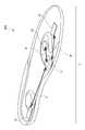
- FIG. 2 is a diagram illustrating an insole as an example of an article on which a transmission device used in this service is mounted.
- the transmission device 1 used in this service can be mounted on a shoe insole 500.
- the transmitting device 1 mounted on the shoe insole 500 in this manner (or the insole 500 mounted with the transmitting device 1) is hereinafter referred to as an “insole type transmitting device 1”.
- the insole type transmitting device 1 is mounted in advance on the shoes worn by the subject H (laid on the inside of the shoes), so that whenever the subject H steps on the shoes (insole 500), the subject Person information can be transmitted.
- the transmission device 1 includes a management unit 11, a detection unit 12 that detects pressure, and a power supply unit 13.
- a flexible substrate F is connected between the management unit 11 and the detection unit 12 and between the management unit 11 and the power supply unit 13.
- the specific aspect of the flexible substrate F is later mentioned with reference to FIG.
- the arrangement of the management unit 11, the detection unit 12, and the power supply unit 13 illustrated in FIG. 2 is an example, and is not limited to the arrangement illustrated in FIG.
- the management unit 11 and the power supply unit 13 may be placed at a position where a load is not applied as much as possible based on an opinion of an expert related to the sole (for example, an expert of plantar plate therapy).
- the subject H has an arrangement in which both the wearability of the insole 500 and ease of walking (healthy walking) are compatible.
- the management unit 11 includes a board that manages target person information.
- substrate which comprises the management part 11 is not specifically limited, From the structure embedded in the insole 500, it is preferable that it is a small board
- the size of the substrate constituting the management unit 11 is preferably about 19 mm in length, about 26 mm in width, and about 2.6 mm in thickness.
- the detection unit 12 detects a physical quantity based on pressure. Specifically, the detection unit 12 detects the treading force generated by the subject H walking (stepping on).
- the detection unit 12 can be configured by, for example, a piezoelectric element as an element that converts a force applied to a piezoelectric body into a voltage. In other words, the detection unit 12 can be configured by a piezoelectric element or the like that converts a physical quantity based on pressure into an electrical signal.
- the power supply unit 13 supplies power to the management unit 11.
- the power supply unit 13 is constituted by a battery or the like, but the life of the battery or the like is preferably longer than the product life of the insole 500.
- the product life of the insole 500 varies depending on the usage, but for daily use such as walking, it is about 1 year to 1 year and a half, and for light exercise such as sports, the life is about 6 months to 9 months. Become. In the case of intense exercise such as marathon or running, it is 500 km to 1000 km, and in the case of use less frequently such as climbing, the life is 2 to 3 years.
- the main intended use is daily use such as walking, and the life of the insole 500 is about one year to one and a half years, but this is a value that assumes daily use, In reality, it can be assumed that the lifetime is 2 to 3 years. For this reason, in order to eliminate the need to replace or charge the battery of the transmitter 1, a battery life of about 3 years is required, but according to the present invention, a battery life exceeding 3 years can be realized. Can do. A specific basis for realizing a battery life exceeding 3 years will be described later.
- the specific mode of the insole 500 main body is not particularly limited, but it is preferable to use a material or a shape that is resistant to the penetration of water and dust into the substrate constituting the management unit 11.
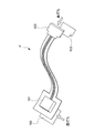
- FIG. 3 is a diagram showing an example of the flexible substrate F shown in FIG.
- the flexible substrate F is a substrate composed of an electronic component 101 and a connector 102.
- the electronic component 101 constitutes the management unit 11 in FIG.
- the connector 102 is a part that electrically connects the management unit 11 (electronic component 101) to the detection unit 12 and the power supply unit 13. Both the electronic component 101 and the connector 102 are lined with a reinforcing material 103.
- the flexible substrate F can be formed of a thin and soft substrate that can be bent or folded. Thereby, even if the transmitter 1 is embedded in a material that can be bent flexibly, such as the insole 500, there is no risk of breakage or the like.
- FIG. 4 is an image diagram illustrating an example of the configuration of the insole type transmission device 1.
- the configuration shown in FIG. 4 is a specific example for explaining the outline of the service, and the functional configuration of the transmission device 1 will be described later with reference to FIG.
- the detection unit 12 (for example, a piezoelectric element) generates power with the pedal force of the subject H and inputs power to the power supply IC 110.
- step S12 the power supply unit 13 (for example, a battery) constantly supplies power to the power supply IC 110. However, control of power supply from the power supply unit 13 to the power supply IC 110 is executed by the power supply IC 110.
- the power supply unit 13 for example, a battery
- step S ⁇ b> 13 the power supply IC 110 inputs power to the transmission unit 112.
- step S14 the transmitter 112 transmits a radio wave on which the subject information is superimposed.
- the transmission unit 112 it is preferable to employ a low power consumption communication method such as BLE (Blue Tooth Low Energy) (registered trademark).
- BLE Bluetooth Tooth Low Energy
- the battery life is about 8 months to 1 year if it is configured to transmit every second with a conventional beacon or the like. turn into. That is, when the battery capacity is 165 mAh and the power consumption per beacon transmission is 80 ⁇ Ws, the battery life is 257.8 days.
- the lifetime of the battery is about 3 to 7 years, and the lifetime is dramatically extended. That is, when the average number of steps per day of the subject H is 10800 steps and the life / death monitoring radio wave is generated every 30 seconds, the life of the battery is 2690.22 days. Thereby, since the life of the power supply unit 13 can be dramatically extended, a material that extends the life of the insole 500 while satisfying the condition that the life of the power supply unit 13 is longer than the life of the insole 500 is adopted. Can do.
- the specific size of the transmission part 112 is not specifically limited. For example, when the transmitter 112 is a BLE module, it can be about 7.9 mm long and about 11.5 mm wide. Moreover, it is preferable that the thickness of the whole management part 11 containing a BLE module shall be about 2.6 mm.
- FIG. 5 is a diagram showing the thickness of the insole type transmission device 1.
- the insole type transmitter 1 having a thickness X of about 10 mm is used.
- the subject person H can obtain a degree of freedom of wearing and can deal with a wide variety of shoes (footwear). That is, the insole type transmission device 1 can be worn on the shoes that the subject person H is familiar with.
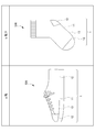
- FIG. 6 is a schematic diagram showing an example of an article on which the transmission device used in the service of FIG. 1 is mounted, and an example different from the example of FIG.
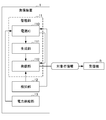
- FIG. 6 is a block diagram illustrating an example of a functional configuration of the transmission device 1.
- the transmission device 1 includes a management unit 11, a detection unit 12, and a power supply unit 13.
- the management unit 11 includes a power supply IC 110, a generation unit 111, and a transmission unit 112.
- the power supply IC 110 inputs power to the generation unit 111 and the transmission unit 112 using the input of power from the detection unit 12 as a trigger.
- the generation unit 111 generates target person information using the power input from the power supply IC 110.
- the transmission unit 112 transmits the target person information generated by the generation unit 111 using the power input from the power supply IC 110.
- the target person information transmitted from the transmitter 112 is received by the receiver R.
- the detection unit 12 generates electric power with the treading force of the target person H and inputs electric power to the power supply IC 110.
- the power supply unit 13 constantly supplies power to the power supply IC 110. However, control of power supply from the power supply unit 13 to the power supply IC 110 is executed by the power supply IC 110.
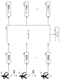
- FIG. 8 is a diagram showing the configuration of the information processing system of the present invention.
- the information processing system shown in FIG. 8 includes a transmitting device 1, a server 2, receivers R1 to Rm (m is an integer value of 1 or more), and user terminals 3-1 to 3-p (p is an integer of 1 or more). Numerical value).
- a transmitting device 1 a server 2
- receivers R1 to Rm m is an integer value of 1 or more
- user terminals 3-1 to 3-p p is an integer of 1 or more. Numerical value
- Numerical value Numerical value
- the transmitting device 1 and the receivers R1 to Rm can be connected by predetermined wireless communication including short-range wireless communication such as BLE.
- the server 2, the receivers R1 to Rm, and the user terminals 3-1 to 3-p are connected to each other via a predetermined network N such as the Internet.
- the subject terminal 4 operated by the subject H is also connected to each other via the network N.
- the transmission device 1 is a device mounted on an insole 500 of a shoe worn by the subject person H. Specifically, the transmission device 1 transmits the subject information in response to the pedaling force of the subject H.
- the transmission device 1 is composed of, for example, a beacon.
- the receivers R1 to Rm receive the target person information transmitted from the transmission device 1 and transfer it to the server 2 together with the receiver position information of the own device.
- the receivers R1 to Rm receive the target person information transmitted from the transmission device 1 and transfer it to the server 2 together with the receiver position information of the own device.
- the server 2 is an information processing apparatus managed by a service provider (not shown).
- the server 2 executes various processes for realizing this service while appropriately communicating with the receivers R1 to Rm and the user terminals 3-1 to 3-p. Further, the server 2 detects the going out of the target person H by performing analysis based on the target person information and the receiver position information. In addition, the server 2 notifies the user terminal 3 that the target person H has gone out.
- Each of the user terminals 3-1 to 3-p is an information processing apparatus operated by each of the users U1 to Up (FIG. 1).
- Each of the user terminals U1 to Up is configured by a personal computer, a smartphone, a tablet, or the like.
- Each of the user terminals 3-1 to 3-p accepts an input operation necessary for each of the users U1 to Up to use this service, and transmits information indicating the input contents to the server 2.
- each of the user terminals 3-1 to 3-p displays various information transmitted from the server 2 under the control of the user terminal 3-1 or the server 2 itself.
- a dedicated application for receiving provision of the service is installed in each of the user terminals 3-1 to 3-p.
- the user U when it is expressed as “the user U operates the user terminal 3”, it means that the user U activates a dedicated application installed in the user terminal 3 and performs various operations. It means that.
- the user terminals 3-1 to 3-p are collectively referred to as “user terminal 3”.
- the receivers R1 to Rm when it is not necessary to distinguish each of the receivers R1 to Rm, these are collectively referred to as “receiver R”.
- a service provider (not shown) can provide a service that is highly convenient for the user U and the target person H.
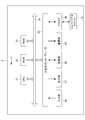
- FIG. 9 is a block diagram illustrating an example of a hardware configuration of the server 2 configuring the information processing system of FIG.
- the server 2 includes a CPU (Central Processing Unit) 21, a ROM (Read Only Memory) 22, a RAM (Random Access Memory) 23, a bus 24, an input / output interface 25, an input unit 26, an output unit 27, A storage unit 28, a communication unit 29, and a drive 30.
- CPU Central Processing Unit
- ROM Read Only Memory
- RAM Random Access Memory
- the CPU 21 executes various processes according to a program recorded in the ROM 22 or a program loaded from the storage unit 28 to the RAM 23.
- the RAM 23 appropriately stores data necessary for the CPU 21 to execute various processes.
- the CPU 21, ROM 22, and RAM 23 are connected to each other via a bus 24.
- An input / output interface 25 is also connected to the bus 24.
- An input unit 26, an output unit 27, a storage unit 28, a communication unit 29, and a drive 30 are connected to the input / output interface 25.
- the input unit 26 is configured with various hardware buttons and the like, and inputs various information according to an instruction operation by the operator.
- the output unit 27 is configured by a display such as a liquid crystal and displays various images.
- the storage unit 28 is configured by a DRAM (Dynamic Random Access Memory) or the like, and stores various data.
- the communication unit 29 controls communication with other devices (receivers R1 to Rm and user terminals 3-1 to 3-p) via the network N including the Internet.
- the drive 30 is provided as necessary.
- a removable medium 41 made of a magnetic disk, an optical disk, a magneto-optical disk, a semiconductor memory, or the like is appropriately worn on the drive 30.
- the program read from the removable medium 41 by the drive 30 is installed in the storage unit 28 as necessary.
- the removable medium 41 can also store various data stored in the storage unit 28 in the same manner as the storage unit 28.
- the receiver R, the user terminal 3, and the target person terminal 4 (not shown) in the information processing system of FIG. 8 also have the hardware configuration shown in FIG.
- the input unit 26 and the output unit 27 have touch panels.
- the “information generation process” refers to a process in which the server 2 generates information indicating the position and state of the target person H based on the acquired target person information and the receiver position information.
- the “information providing process” refers to a process in which the server 2 provides information indicating the generated position and state of the target person H to the user U.
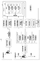
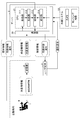
- FIG. 10 is a functional block diagram showing a functional configuration for executing the information providing process among the functional configurations of the information processing system including the server 2 of FIG.
- an acquisition unit 211 and a generation unit 212 function.
- the providing unit 213 and the receiving unit 214 function as necessary.
- the acquisition unit 211 acquires receiver information transmitted from each of the receivers R1 to Rm.
- the “receiver information” refers to information including target person information transmitted from the transmitting device 1 and received by the receiver R, and receiver position information.
- the generation unit 212 Based on the receiver information acquired by the acquisition unit 211, the generation unit 212 generates information indicating the status of the target person H (hereinafter referred to as “current status information”). Specifically, the generation unit 212 generates current status information by analyzing the receiver information.
- the accepting unit 214 accepts each of the information (hereinafter referred to as “providing request”) transmitted by each of the user terminals 3-1 to 3 -p indicating that the current status information of the target person H is requested.
- the providing unit 213 transmits each of the current status information generated by the generating unit 212 to each of the user terminals 3-1 to 3-p. Specifically, when the provision unit 213 receives a provision request, the provision unit 213 transmits current state information corresponding to the provision request to the user terminal 3. Further, the server 2 can independently determine and transmit without assuming the provision request.
- Each process such as an information providing process can be executed by the server 2 having the above functional configuration.
- the service provider can provide the user U and the target person H with the highly convenient service.
- FIG. 11 is an image diagram showing a case where the information processing system including the server 2 having the functional configuration shown in FIG. 10 is applied to the eyelid search service.
- the target person information transmitted from the transmission device 1 is installed in the site of the care facility B. Received by the receiver R. The target person information received by the receiver R is transmitted to the server 2 as receiver information together with the receiver position information. Then, the server 2 acquires the transmitted receiver information, executes the information providing process described above, and transmits the current status information to the user terminal 3. Thereby, the user U can easily recognize that the target person H is in the site of the care facility B from the current state information transmitted to the user terminal 3.
- the target person information transmitted from the transmission device 1 is It is received by each of the receivers R installed outside the site of the facility B.
- the receiver R can be installed or mounted on, for example, a convenience store, a vending machine, a utility pole, or a collaborator terminal (for example, a smartphone or a tablet) managed by a collaborator.
- the target person information received by the receiver R is transmitted to the server 2 as receiver information together with the receiver position information.
- the server 2 acquires the transmitted receiver information, executes the information providing process described above, and transmits the current status information to the user terminal 3.
- the current status information transmitted from the server 2 to the user terminal 3 includes information such as an alert notification indicating that the target person H is hesitant.
- the user U is outside the facility of the care facility B from the current status information that has been automatically notified of the alert without performing an operation of transmitting a provision request to the server 2 (hesitantly) Can be recognized immediately.
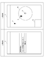
- FIG. 12 is a diagram showing a specific example of the current status information that is automatically notified of alerts from the server 2 to the user terminal 3.
- this service includes a service for detecting the habit of the target person H.
- the specific example a shown in FIG. 12 shows a specific example of the screen of the user terminal 3 when a message indicating that a wrinkle has been detected is automatically displayed as an alert. That is, when the target 2's trap is detected by the server 2, a message such as “detected trap” or “Mr. A's (target H) trap” pops up on the screen of the user terminal 3, for example. Is done. The message pop-up displayed on the screen of the user terminal 3 can be closed by pressing a button labeled “Close”.
- the specific example b shown in FIG. 12 shows a specific example when a map showing the position of the deaf person is displayed on the screen of the user terminal 3. That is, when the target person H's trap is detected by the server 2, information indicating the current location of the target person H detected as a trap, information indicating the position of the care facility B, on the screen of the user terminal 3, The information indicating the safe area Sa, the information indicating the position of the receiver R, the area Da capable of displaying the predetermined information, and the like are displayed together with the map.
- FIG. 13 is an image diagram showing a case where an information processing system including the server 2 having the functional configuration shown in FIG. 10 is applied to an independent support service.
- This service includes a service that supports the independence of the target person H (hereinafter referred to as “independence support service”). As shown in FIG. 13, when the target person H wearing the transmission device 1 is walking in the site of the care facility B, the target person information transmitted from the transmission device 1 is installed in the site of the care facility B. Received by the receiver R.
- the subject information can include the context information of the subject H.
- the “context” is a concept indicating all of the internal state and the external state of the subject H.
- the internal state of the subject person H refers to the physical condition of the subject person H, emotion (feeling or psychological state), or the like.
- the external state of the subject person H is the space around the subject person H in addition to the spatial or temporal placement position of the subject person H (the temporal placement position refers to the current time, for example). It also refers to a predetermined state distributed in the direction or time direction (or distributed in any direction).
- the context information includes, for example, information on the activity of the subject H (number of steps, etc.), information on stress, information on the environment, subjective information on physical condition, age, height, weight, body temperature, and body fat percentage of the subject H.
- the objective information regarding the physical characteristics of the subject person H, and the information regarding the schedule of the subject person H such as the action history of the subject person H can be included.
- the specific method by which the server 2 acquires context information is not particularly limited.
- information provided from an external server may be acquired as context information, or the transmitter 1 may be provided with various sensors (not shown), and information detected by these sensors may be acquired as context information. Also good.
- you may acquire the information separately managed in the facilities etc. which the user U manages, such as care facility B, as context information.
- the target person information received by the receiver R is transmitted to the server 2 as receiver information together with the receiver position information. Then, the server 2 acquires the received receiver information, generates the current state information by executing the above-described information providing process, and transmits it to the user terminal 3.
- the server 2 together with the receiver position information, information for uniquely identifying the target person H (hereinafter referred to as “target person ID”) and information regarding the number of steps of the target person H (hereinafter referred to as “step number information”). )) And information about the stress distribution (stress distribution information) at least.
- the server 2 generates the current state information by executing the above-described information providing process, but in the example of FIG. 13, the current state information including information indicating the “degree of independence” of the target person H is generated.
- the “degree of independence” refers to an index that indicates how much the target person H can live in daily life without requiring the power of others.
- the degree of independence can be calculated based on the context information included in the target person information. Specifically, for example, information managed in the external system SS managed by the care facility B and information detected by various sensors (not shown) of the transmission device 1 are acquired as context information, and the context information is included in this context information. Based on this, the degree of independence is calculated.
- the server 2 transmits information indicating the calculated degree of independence of the target person H to the user terminal 3. Thereby, the user U can easily grasp the current state of the target person H from the current state information transmitted to the user terminal 3 and including information indicating the degree of independence.
- FIG. 14 is an image diagram showing a case where an information processing system including the server 2 having the functional configuration shown in FIG. 10 is applied to a vision support service.
- This service includes a service (hereinafter referred to as “sight support service”) that supports the subject H who has a handicap in visual acuity such as amblyopia.
- the target person H who receives the provision of the visual acuity support service carries the target person terminal 4 and acquires the current status information using the target person terminal 4. Specifically, for example, the target person H can acquire the current state information through hearing through the earphone Y connected to the target person terminal 4.
- the target person information transmitted from the transmitting device 1 is a receiver installed in the site of the nursing facility B. Received by R.
- the subject information includes the context information of the subject H acquired by the above-described method.
- the target person information including the context information received by the receiver R is transmitted to the server 2 as receiver information together with the receiver position information. Then, the server 2 acquires the received receiver information, generates the current status information by executing the above-described information providing process, and transmits the current status information to the target person terminal 4 and the user terminal 3.
- the server 2 acquires information necessary for supporting the visual acuity of the target person H (hereinafter, “sight support information”) from the external system SS together with the receiver information, and based on the acquired information. Then, the information providing process described above is executed.
- the external system SS includes imaging means (for example, a camera) that can image the subject H, sensing equipment that can acquire information indicating the state of the subject H, and the like.
- the “sight support information” includes data of the captured image of the subject H captured by the imaging means of the external system SS and information indicating the state of the subject H detected by the sensing device.
- the server 2 generates the current status information based on the receiver information and the vision support information.
- information for preventing an accident of the target person H (hereinafter referred to as “accident prevention information”).
- current information including information for improving care work for the target person H by the caregiver (hereinafter referred to as “work improvement information”) is generated.
- the server 2 appropriately transmits current status information including the generated accident prevention information and business improvement information to the target person terminal 4 and the user terminal 3.
- the subject person H can depend on the present condition information containing the accident prevention information transmitted to the subject person terminal 4, and can send a daily life.
- the user U can easily acquire information necessary for business improvement based on the current status information including the business improvement information transmitted to the user terminal 3.
- FIG. 15 is an image diagram showing a case where an information processing system including the server 2 having the functional configuration shown in FIG. 10 is applied to a sports data providing service.
- This service includes a service (hereinafter referred to as “sports data providing service”) that supports a user U (for example, a coach or the like) who is in a position to support the target person H who is a sports player.
- sports data providing service a service that supports a user U (for example, a coach or the like) who is in a position to support the target person H who is a sports player.
- the user U who receives the provision of the sports data providing service wears sports shoes 500 on which the transmission device 1 is mounted and performs sports.
- the target person information is transmitted from the transmission device 1 by the target person H running.
- the target person information transmitted from the target person H includes at least a target person ID, step count information, and stress distribution information.
- the target person information transmitted from the transmitting device 1 is received by the receiver R installed in the site of the care facility B.
- the target person information including the context information received by the receiver R is transmitted to the server 2 as receiver information together with the receiver position information.
- the server 2 acquires the received receiver information, generates the current status information by executing the above-described information providing process, and sends the current status information to the target terminal 4 (not shown) and the user terminal 3. Send.
- the server 2 acquires information for supporting the user U who supports the target person H who performs sports as context information from the external system SS together with the receiver information, and based on these acquired information, The information providing process described above is executed.
- the external system SS includes an imaging unit (for example, a camera) that can capture an image of the subject person H who performs sports, a sensing device that can acquire information indicating the state of the target person H, and the like.
- the context information provided by the external system SS includes data of the captured image of the subject person H captured by the imaging means of the external system SS and information indicating the state of the subject person H detected by the sensing device. included.
- the server 2 generates the current state information based on the receiver information and the context information provided by the external system SS.
- information indicating the amount of exercise of the subject H (hereinafter, “exercise amount information”). )
- technical information (hereinafter referred to as “technical information”) such as how to step on the foot of the subject H, and the like.
- the technical information for example, information on how to step on the jump crossing is compared with first-class player information (example information).
- the server 2 appropriately transmits current status information including the generated exercise amount information and technical information in response to a provision request from the user terminal 3. Accordingly, the user U can appropriately support the target person H by referring to the current state information including the exercise amount information and the technical information transmitted from the server 2 to the user terminal 3.
- FIG. 16 is an image diagram showing a case where an information processing system including the server 2 having the functional configuration shown in FIG. 10 is applied to a tracking service.
- This service includes a service (hereinafter referred to as a “tracking service”) that supports management operations of the manager of the ski facility and the like by tracking the user and mountain climber of the ski facility.
- a target person H a ski facility user or a mountain climber
- the target person information is transmitted from the transmission device 1 as the target person H walks.
- the target person information transmitted from the target person H includes at least information (for example, a beacon signal) used for specifying the position of the transmission device 1.
- the target person information transmitted from the transmitting device 1 is received by the receiver R installed in the site of the ski facility or on the mountain path.
- the target person information received by the receiver R is transmitted to the server 2 as receiver information together with the receiver position information.
- the server 2 acquires the received receiver information, generates the current status information by executing the above-described information providing process, and sends the current status information to the target terminal 4 (not shown) and the user terminal 3. Send.
- the server 2 generates the current status information based on the receiver information.
- the current status information including information indicating the position of the target person H is generated.
- alert information or the like is generated as current information.
- the server 2 appropriately transmits the current status information including the generated information indicating the position of the target person H and the alert information to the user terminal 3. Thereby, the user U can take an appropriate response based on the current state information transmitted from the server 2 to the user terminal 3.
- FIG. 17 is an image diagram showing a case where an information processing system including the server 2 having the functional configuration shown in FIG. 10 is applied to an operation management support service.
- This service detects the accelerator work of the subject person H who drives the car and supports the person (user U) who manages the driving of the subject person H, including prevention of traffic accidents (hereinafter referred to as “driving management”). Called support services).
- driving management the target person H to be managed wears shoes equipped with the transmission device 1 and drives the automobile. Thereby, for example, subject person information is transmitted from transmitting device 1 when subject person H steps on an accelerator pedal or a brake pedal.
- the target person information transmitted from the transmitting device 1 is received by the receiver R installed in the car.
- the target person information received by the receiver R is transmitted to the server 2 as receiver information together with the receiver position information.
- the server 2 acquires the received receiver information, generates the current status information by executing the above-described information providing process, and sends the current status information to the target terminal 4 (not shown) and the user terminal 3. Send.
- the server 2 acquires information for supporting the person (user U) who manages the driving of the target person H as context information from the external system SS together with the receiver information, and based on the acquired information. Then, the information providing process described above is executed.
- the external system SS includes an imaging means (for example, a camera) that can image the subject person H who drives the car, a sensing device that can acquire information indicating the state of the subject person H, and the like.
- the context information provided by the external system SS includes data of the captured image of the subject person H captured by the imaging means of the external system SS and information indicating the state of the subject person H detected by the sensing device. included.
- the server 2 generates the current status information based on the receiver information and the context information provided by the external system SS.
- information on driving technology including the accelerator work of the target person H (
- current status information including the “driving technology information”) and personal information of the target person H (hereinafter referred to as “personality information”) is generated.
- personal information including the “driving technology information”
- alert information or the like is generated as the current state information.
- the server 2 appropriately transmits current status information including the generated driving information and technical information in response to a provision request from the user terminal 3.
- the alert information is transmitted regardless of whether there is a provision request from the user terminal 3.
- the person (user U) who manages the driving of the target person H refers to the current state information including the driving technique information, the personality information, and the alert information transmitted from the server 2 to the user terminal 3.
- the operation of H can be managed appropriately.
- FIG. 18 is an image diagram showing a case where an information processing system including the server 2 having the functional configuration shown in FIG. 10 is applied to a factory management support service.
- This service includes a service (hereinafter referred to as “factory management support service”) that detects the behavior of the target person H engaged in work as a worker in a factory facility and supports a person (user U) who manages the factory facility. Call).
- the factory management support service As shown in FIG. 18, according to the factory management support service, the target person H to be managed in the factory facility engages in work while wearing work shoes 100 on which the transmission device 1 is mounted. Accordingly, the subject person information is transmitted from the transmission device 1 in accordance with an action such as the subject person H walking in the factory.
- the target person information transmitted from the transmitting device 1 is received by the receiver R installed in the factory facility.
- the target person information received by the receiver R is transmitted to the server 2 as receiver information together with the receiver position information.
- the server 2 acquires the transmitted receiver information, generates the current status information by executing the above-described information providing process, and transmits the current status information to the user terminal 3.
- the server 2 acquires, as context information, information useful for supporting a person (user U) who manages the behavior of the target person H in the factory facility from the external system SS together with the receiver information. Based on the acquired information, the information providing process described above is executed.
- the external system SS includes an imaging means (for example, a camera) that can capture an image of the subject person H engaged in work in the factory facility, a sensing device that can acquire information indicating the state of the subject person H, and the like.
- the context information provided by the external system SS includes data of the captured image of the subject person H captured by the imaging means of the external system SS and information indicating the state of the subject person H detected by the sensing device. included.
- the server 2 generates the current state information of the target person H based on the receiver information and the context information provided by the external system SS. In the example of FIG. 18, it is necessary for improving the work in the factory. Current status information including information to be generated is generated. Further, when the target person H enters a dangerous zone in the factory, alert information or the like is generated as the current status information.
- the server 2 appropriately transmits the generated current status information in response to a provision request from the user terminal 3.
- the alert information is transmitted regardless of whether there is a provision request from the user terminal 3.
- the person (user U) who manages the behavior of the target person H in the factory facility can obtain information and alert information necessary for improving the work in the factory transmitted from the server 2 to the user terminal 3.
- the behavior of the target person H in the factory facility can be appropriately managed. In addition, it is possible to improve operations in factory facilities.
- the target person information transmitted from the transmission device 1 does not include information indicating the position of the transmission device 1. That is, the current location of the transmission device 1 is specified based on the information indicating the position of the receiver R that has received the target person information transmitted from the transmission device 1.
- Information indicating the position of the transmission device 1 may be included in the target person information transmitted from the transmission device 1.
- the transmission device 1 is mounted on the insole 500.
- the transmission device 1 is not particularly limited thereto.
- the transmission device 1 may be attached to an arbitrary portion of the foot of the subject H.
- the method used for transmitting information from the transmitting device 1 is a method for transmitting a beacon signal compliant with Bluetooth (registered trademark).
- a system using a set of LPRa (Low Power Wide Area) + GPS (Global Positioning System) by LoRa may be used.
- the power source of the transmission device 1 is configured to employ a battery such as a button battery or a magnesium battery, but is not particularly limited thereto, and may be an external power source or automatic power generation. But you can.
- the automatic power generation method is not particularly limited, and any surface current, thermoelectric power generation, power generation fiber, or the like can be employed.
- the electric power generated by the automatic power generation may be stored.
- the method for storing electricity is not particularly limited, and for example, a method using a magnesium battery or a super capacitor can be employed.
- a piezoelectric element that generates electric power when the subject H steps on the insole 500 is used as the detection unit 12 of the transmission device 1, but is not particularly limited thereto.
- Various sensors such as an acceleration sensor, a gyro sensor, and a temperature sensor can be used.
- the service can be used in the user terminal 3 and the target person terminal 4 by starting the dedicated application installed in the user terminal 3 and the target person terminal 4.
- the service may be used by accessing a predetermined website and performing a predetermined login operation without installing a dedicated application.
- system configuration shown in FIG. 8 and the hardware configuration of the server 2 shown in FIG. 9 are merely examples for achieving the object of the present invention, and are not particularly limited.
- FIGS. 7 and 10 are merely examples, and are not particularly limited. That is, it is sufficient that the information processing apparatus or the information processing system has a function capable of executing the above-described series of processes as a whole, and what functional blocks are used to realize this function are particularly illustrated in FIG. It is not limited to the example of FIG.
- the location of the functional block is not limited to that shown in FIGS. 7 and 10 and may be arbitrary.
- one functional block may be constituted by hardware alone, software alone, or a combination thereof.
- a program constituting the software is installed on a computer or the like from a network or a recording medium.
- the computer may be a computer incorporated in dedicated hardware.
- the computer may be a computer capable of executing various functions by installing various programs, for example, a general-purpose smartphone or personal computer other than a server.
- a recording medium including such a program is not only constituted by a removable medium distributed separately from the apparatus main body in order to provide the program to each user, but also provided to each user in a state of being incorporated in the apparatus main body in advance. It is composed of a provided recording medium or the like.
- the steps for describing the program recorded on the recording medium are not limited to the processing performed in time series according to the order, but may be performed in parallel or individually even if not necessarily performed in time series.
- the process to be executed is also included.
- system means an overall apparatus composed of a plurality of devices, a plurality of means, and the like.
- the information processing apparatus to which the present invention is applied only needs to have the following configuration, and can take various embodiments. That is, the information processing apparatus to which the present invention is applied (for example, the transmitting apparatus 1 in FIG. 1) Detection means (for example, the detection unit 12 in FIG. 7) for detecting a physical quantity based on pressure from at least a part of the human foot (for example, the sole of the foot) When the physical quantity detected by the detection unit satisfies a predetermined standard (for example, when a predetermined threshold is exceeded), a transmission unit (for example, the transmission unit 112 in FIG. 7) that transmits predetermined information; Is provided.
- a predetermined standard for example, when a predetermined threshold is exceeded
- the transmission means can transmit information used for specifying a position where the own device is present as the predetermined information.
- the information processing apparatus is mounted on an article (for example, the insole 500) in contact with or close to the person's foot,
- the detection means can detect a pedaling force or a physical quantity based on the pedaling force.
- the subject person H can transmit information indicating the current state including his / her current position to the other person only by wearing the insole 500.
- an information processing system of one embodiment of the present invention includes: A first information processing device (for example, the transmitting device 1 in FIG. 8) worn on an article that is in contact with or close to the foot of a person (for example, the subject person H), and a second information processing device (for example, a predetermined processing related to the person)
- the first information processing apparatus Detecting means for detecting a physical quantity based on pressure from at least a part of the person's foot for example, the detecting unit 12 in FIG.
- a transmission means for transmitting the first information for example, the transmission unit 112 in FIG. 7
- the second information processing apparatus Acquisition means for acquiring the first information for example, the acquisition unit 211 in FIG. 10
- Execution means for example, the generation unit 212 and the provision unit 213 in FIG. 10 that executes the predetermined process based on the first information; Is provided.
- the target person H can easily acquire information indicating the current state of the target person H who is difficult to transmit information indicating his / her current state to others.
- the acquisition unit further acquires second information (for example, context information) indicating a context related to the person.
- the execution means can execute the predetermined process based on the second information in addition to the first information.
- the target person H can easily acquire information indicating the current state of the target person H that is difficult to convey to the other person information indicating the current state including context information.
- the execution means can execute the predetermined process using the position of the person specified based on the first information.
- the target person H can easily acquire information indicating the current state of the target person H who is difficult to transmit information indicating the current state including the current location to other persons.
- the second information processing apparatus may transmit some information such as a result of a predetermined process as FB information to the first information processing apparatus.
- the server 2 may transmit information provided to the user U (information indicating the current position of the subject person H, the culling route, etc.) to the transmitting device 1.
- the transmission device 1 may have a function of receiving the information and a function of notifying the user U of the information or information based on the information.
- the transmission device 1 may notify the target person H of the current position of the target person H, or notify the target person H of any warning if the current position of the target person H is a position to be warned. May be.
- the notification method in this case is not particularly limited, and in addition to a method of notifying by an output mechanism (speaker, display, etc.) possessed by the transmission device 1 itself, a device other than the transmission device 1 (for example, the target person H) Arbitrary methods such as a method of informing by a wearable device (not shown) that is held may be employed.
Landscapes
- Business, Economics & Management (AREA)
- Emergency Management (AREA)
- Physics & Mathematics (AREA)
- General Physics & Mathematics (AREA)
- Health & Medical Sciences (AREA)
- Engineering & Computer Science (AREA)
- General Health & Medical Sciences (AREA)
- Gerontology & Geriatric Medicine (AREA)
- Signal Processing (AREA)
- Psychiatry (AREA)
- Computer Networks & Wireless Communication (AREA)
- Psychology (AREA)
- Social Psychology (AREA)
- Child & Adolescent Psychology (AREA)
- Footwear And Its Accessory, Manufacturing Method And Apparatuses (AREA)
- Telephonic Communication Services (AREA)
- Medical Treatment And Welfare Office Work (AREA)
- Position Fixing By Use Of Radio Waves (AREA)
- Alarm Systems (AREA)
- Traffic Control Systems (AREA)
- Navigation (AREA)
Priority Applications (4)
| Application Number | Priority Date | Filing Date | Title |
|---|---|---|---|
| JP2019534777A JPWO2019172441A1 (ja) | 2018-03-09 | 2019-03-08 | 情報処理装置、及び情報処理システム |
| CN201980017303.5A CN111819832A (zh) | 2018-03-09 | 2019-03-08 | 信息处理装置和信息处理系统 |
| US16/978,642 US20210049889A1 (en) | 2018-03-09 | 2019-03-08 | Information processing device and information processing system |
| KR1020207025909A KR20200118844A (ko) | 2018-03-09 | 2019-03-08 | 정보 처리 장치, 및 정보 처리 시스템 |
Applications Claiming Priority (2)
| Application Number | Priority Date | Filing Date | Title |
|---|---|---|---|
| JP2018043035 | 2018-03-09 | ||
| JP2018-043035 | 2018-03-09 |
Publications (1)
| Publication Number | Publication Date |
|---|---|
| WO2019172441A1 true WO2019172441A1 (ja) | 2019-09-12 |
Family
ID=67846075
Family Applications (1)
| Application Number | Title | Priority Date | Filing Date |
|---|---|---|---|
| PCT/JP2019/009454 Ceased WO2019172441A1 (ja) | 2018-03-09 | 2019-03-08 | 情報処理装置、及び情報処理システム |
Country Status (6)
| Country | Link |
|---|---|
| US (1) | US20210049889A1 (enExample) |
| JP (2) | JPWO2019172441A1 (enExample) |
| KR (1) | KR20200118844A (enExample) |
| CN (1) | CN111819832A (enExample) |
| TW (1) | TW201944361A (enExample) |
| WO (1) | WO2019172441A1 (enExample) |
Families Citing this family (3)
| Publication number | Priority date | Publication date | Assignee | Title |
|---|---|---|---|---|
| JP7596652B2 (ja) * | 2020-06-29 | 2024-12-10 | 日本電気株式会社 | 監視装置、監視システム、監視方法及び監視プログラム |
| DE102020209650A1 (de) * | 2020-07-30 | 2022-02-03 | Volkswagen Aktiengesellschaft | Verfahren zum Erfassen von Personen und/oder Objekten im Innenraum eines Kraftfahrzeugs und Kraftfahrzeug |
| JP2022146147A (ja) * | 2021-03-22 | 2022-10-05 | セイコーエプソン株式会社 | 通信方法、通信装置。 |
Citations (2)
| Publication number | Priority date | Publication date | Assignee | Title |
|---|---|---|---|---|
| JP3125563U (ja) * | 2005-12-08 | 2006-09-28 | 株式会社エー・エス・ブレインズ | 徘徊防止システム |
| JP2016073366A (ja) * | 2014-10-03 | 2016-05-12 | 克弥 西沢 | 歩行による発電機能と無線通信および測位機能を備えた無線通信機および無線通信機を中敷として用いた歩行者の位置監視システム |
Family Cites Families (17)
| Publication number | Priority date | Publication date | Assignee | Title |
|---|---|---|---|---|
| JPH0412099U (enExample) * | 1990-05-16 | 1992-01-31 | ||
| JPH11250377A (ja) * | 1997-02-04 | 1999-09-17 | Masanobu Kujirada | 携帯型安全システム |
| JP2000020629A (ja) | 1998-07-07 | 2000-01-21 | Toshiba Corp | 福祉支援システム |
| NZ611197A (en) | 2010-10-29 | 2015-07-31 | Orpyx Medical Technologies Inc | Peripheral sensory and supersensory replacement system |
| KR101629981B1 (ko) | 2011-04-04 | 2016-06-13 | 엘에스산전 주식회사 | Rtls 태그 장치 및 위치추적 시스템 |
| CN103697884B (zh) * | 2013-11-30 | 2017-03-01 | 北京智谷睿拓技术服务有限公司 | 定位方法、设备、系统及装置 |
| CN107251031A (zh) * | 2015-01-13 | 2017-10-13 | 戴尔斯生活有限责任公司 | 用于监测和增强人体健康的系统、方法和制品 |
| JP2017045366A (ja) | 2015-08-28 | 2017-03-02 | スター精密株式会社 | 外出監視システム |
| JP2017076326A (ja) * | 2015-10-16 | 2017-04-20 | 株式会社デンソー | 発信機管理システム |
| CN105212909A (zh) * | 2015-10-31 | 2016-01-06 | 愈先梅 | 基于物联网、云计算和大数据分析的智能可穿戴设备健康安全系统 |
| JP6363633B2 (ja) | 2016-01-15 | 2018-07-25 | キャプテン山形株式会社 | 徘徊行方不明者防止ネットワークシステム、およびその制御方法 |
| JP2016218992A (ja) * | 2016-01-18 | 2016-12-22 | 克巳 小松 | 救援方法、救援システム、徘徊者保護方法および徘徊者保護システム |
| DE102016201152B4 (de) | 2016-01-27 | 2017-08-03 | Adidas Ag | Energie gewinnende Sohle |
| JP2017217213A (ja) | 2016-06-07 | 2017-12-14 | シャープ株式会社 | 歩行連動通信装置、歩行連動装置、および歩行連動システム |
| JP6703737B2 (ja) * | 2016-06-20 | 2020-06-03 | 株式会社音力発電 | 制御システム |
| JP2018037050A (ja) * | 2016-09-01 | 2018-03-08 | 株式会社トレイル | 移動体位置情報の検出装置 |
| CN206164854U (zh) | 2016-10-26 | 2017-05-10 | 张磊 | 隐蔽式个人位置追踪鞋垫 |
-
2019
- 2019-03-08 CN CN201980017303.5A patent/CN111819832A/zh active Pending
- 2019-03-08 KR KR1020207025909A patent/KR20200118844A/ko not_active Ceased
- 2019-03-08 TW TW108107738A patent/TW201944361A/zh unknown
- 2019-03-08 WO PCT/JP2019/009454 patent/WO2019172441A1/ja not_active Ceased
- 2019-03-08 JP JP2019534777A patent/JPWO2019172441A1/ja active Pending
- 2019-03-08 US US16/978,642 patent/US20210049889A1/en not_active Abandoned
- 2019-12-16 JP JP2019226687A patent/JP7049681B2/ja active Active
Patent Citations (2)
| Publication number | Priority date | Publication date | Assignee | Title |
|---|---|---|---|---|
| JP3125563U (ja) * | 2005-12-08 | 2006-09-28 | 株式会社エー・エス・ブレインズ | 徘徊防止システム |
| JP2016073366A (ja) * | 2014-10-03 | 2016-05-12 | 克弥 西沢 | 歩行による発電機能と無線通信および測位機能を備えた無線通信機および無線通信機を中敷として用いた歩行者の位置監視システム |
Also Published As
| Publication number | Publication date |
|---|---|
| JPWO2019172441A1 (ja) | 2020-04-16 |
| CN111819832A (zh) | 2020-10-23 |
| JP2020052058A (ja) | 2020-04-02 |
| KR20200118844A (ko) | 2020-10-16 |
| US20210049889A1 (en) | 2021-02-18 |
| TW201944361A (zh) | 2019-11-16 |
| JP7049681B2 (ja) | 2022-04-07 |
Similar Documents
| Publication | Publication Date | Title |
|---|---|---|
| JP6934929B2 (ja) | 多機能スマート移動補助装置及び利用方法 | |
| US9847006B2 (en) | Fall detector and alert system | |
| Montanini et al. | A footwear-based methodology for fall detection | |
| US9479913B2 (en) | Mobile communication device and communication method | |
| US20120150074A1 (en) | Physical activity monitoring system | |
| US20160174899A1 (en) | Wireless Connected Indoors Slipper and Wireless Connected Footwear and Associated Detection Methods | |
| JP7049681B2 (ja) | 情報処理装置、及び情報処理システム | |
| WO2014182720A1 (en) | Mobile personal emergency response system | |
| US20170086710A1 (en) | Activity amount measuring apparatus, activity amount measuring method, and activity amount measuring program | |
| JP2014007533A (ja) | 徘徊者位置管理システム | |
| Raji et al. | Review of development trends in smart shoe applications | |
| KR102421310B1 (ko) | 파킨슨 환자의 재활을 위한 스마트 걸음 보조 장치 및 방법 | |
| KR20130098533A (ko) | 모바일 단말 기반 유비쿼터스 헬스 헬멧과 신변안전 시스템 | |
| KR20110011195A (ko) | 응급 상태 모니터링 시스템 | |
| KR20180019900A (ko) | 환자 안전을 위한 위치 측위 기반의 환자 안전관리 시스템 | |
| KR101647629B1 (ko) | 보행 보조 장비 | |
| US20220265153A1 (en) | Biological information gathering system and wearable device | |
| KR20190087136A (ko) | 족압을 이용한 스마트 신발 시스템 | |
| JP2019063421A (ja) | ウェアラブル装置 | |
| KR102274822B1 (ko) | 스마트 수제화를 이용한 치매환자 실버케어 모니터링 시스템 | |
| JP7583120B1 (ja) | センサ装置及び歩行情報通信システム | |
| KR20200016439A (ko) | 착용자의 신발에 장착되는 감지모듈을 이용한 보행 모니터링 시스템 | |
| KR20210154361A (ko) | 비대면 체온변화 관리 플랫폼 서비스 시스템 및 방법 | |
| US20250248475A1 (en) | Footwear article | |
| US20230293010A1 (en) | Non-face-to-face body temperature change management platform service system and method |
Legal Events
| Date | Code | Title | Description |
|---|---|---|---|
| ENP | Entry into the national phase |
Ref document number: 2019534777 Country of ref document: JP Kind code of ref document: A |
|
| 121 | Ep: the epo has been informed by wipo that ep was designated in this application |
Ref document number: 19764813 Country of ref document: EP Kind code of ref document: A1 |
|
| ENP | Entry into the national phase |
Ref document number: 20207025909 Country of ref document: KR Kind code of ref document: A |
|
| NENP | Non-entry into the national phase |
Ref country code: DE |
|
| 122 | Ep: pct application non-entry in european phase |
Ref document number: 19764813 Country of ref document: EP Kind code of ref document: A1 |