WO2019163515A1 - 生体センサ - Google Patents
生体センサ Download PDFInfo
- Publication number
- WO2019163515A1 WO2019163515A1 PCT/JP2019/004243 JP2019004243W WO2019163515A1 WO 2019163515 A1 WO2019163515 A1 WO 2019163515A1 JP 2019004243 W JP2019004243 W JP 2019004243W WO 2019163515 A1 WO2019163515 A1 WO 2019163515A1
- Authority
- WO
- WIPO (PCT)
- Prior art keywords
- sensor
- recess
- sensor unit
- housing
- elastic
- Prior art date
- Legal status (The legal status is an assumption and is not a legal conclusion. Google has not performed a legal analysis and makes no representation as to the accuracy of the status listed.)
- Ceased
Links
Images


Classifications
-
- A—HUMAN NECESSITIES
- A61—MEDICAL OR VETERINARY SCIENCE; HYGIENE
- A61B—DIAGNOSIS; SURGERY; IDENTIFICATION
- A61B5/00—Measuring for diagnostic purposes; Identification of persons
-
- A—HUMAN NECESSITIES
- A61—MEDICAL OR VETERINARY SCIENCE; HYGIENE
- A61B—DIAGNOSIS; SURGERY; IDENTIFICATION
- A61B5/00—Measuring for diagnostic purposes; Identification of persons
- A61B5/02—Detecting, measuring or recording for evaluating the cardiovascular system, e.g. pulse, heart rate, blood pressure or blood flow
- A61B5/021—Measuring pressure in heart or blood vessels
- A61B5/022—Measuring pressure in heart or blood vessels by applying pressure to close blood vessels, e.g. against the skin; Ophthalmodynamometers
Definitions
- This disclosure relates to a biosensor.
- Patent Document 1 discloses a sphygmomanometer that measures blood pressure by detecting a Korotkoff sound using a sensor (vibration sensor) disposed in an internal space of the cuff.
- a biological signal such as Korotkoff sound can be detected by a sensor so as not to disturb the cuff occlusion.
- the cuff passes sound from outside. For this reason, when the sound from the outside reaches the sensor, the signal output from the sensor includes not only a signal corresponding to the vibration of the living body but also a signal corresponding to the external sound as noise.
- the present disclosure has been made in view of the above-described circumstances, and an object of the present disclosure is to provide a biological sensor that can suppress external sound from reaching the sensor.
- the biosensor of the present disclosure includes an outer surface in contact with an object, a housing having a recess formed to be recessed from the outer surface, a sensor unit that is disposed inside the recess and detects vibration of the object, An elastic portion that connects the sensor portion to the housing in a manner that allows the displacement to be elastically displaced in a direction in which the concave portion opens.
- the biometric sensor according to the first embodiment of the present disclosure detects vibrations of a human body in a state where the biosensor is in contact with a human body that is an example of a living body (object).
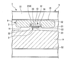
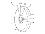
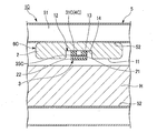
- the biosensor 1 includes a housing 2, a sensor unit 3, and an elastic unit 4.
- the biosensor 1 includes a cuff (attachment) 5.
- the housing 2 has an outer surface 11 (hereinafter referred to as a first outer surface 11) that is brought into contact with the human body H, and a concave portion 12 that is recessed from the first outer surface 11.
- the first outer surface 11 is formed as a flat surface.
- the 1st outer surface 11 may be formed in the curved surface corresponding to the surface of the human body H, for example.
- the opening of the recess 12 is surrounded by the first outer surface 11 of the housing 2. Thereby, the recessed part 12 is sealed with respect to the outside in a state where the first outer surface 11 of the housing 2 is in contact with the human body H.
- the opening of the recess 12 is formed in a circular shape in plan view as viewed from the first outer surface 11 side of the housing 2.
- planar view shape of the opening of the recessed part 12 may be formed in arbitrary shapes, such as polygonal shape.
- the inner surface of the recess 12 has a bottom surface 13 that faces in the direction in which the recess 12 opens, and a side surface that defines the recess 12 and extends from the edge of the bottom surface 13 toward the opening of the recess 12.
- the inner surface of the recessed part 12 may be formed in arbitrary shapes.
- the housing 2 is configured to shield sound.
- casing 2 should just have a certain amount of weight.
- casing 2 is good to be comprised with a material with large specific gravity.
- the housing 2 may be made of a material having a specific gravity larger than that of a cuff 5 described later, for example.
- the housing 2 may be made of metal, may be made of a resin such as a silicone resin, or may be configured by pottery or stone.
- casing 2 should just have rigidity higher than the elastic part 4 mentioned later.
- the sensor unit 3 includes an electret sensor 21 (sensor body) that detects vibration of the human body H.
- the electret sensor 21 is a piezoelectric sensor that is formed in a sheet shape or a film shape and detects vibration (pressure) in the thickness direction and converts it into a voltage.
- the electret sensor 21 has a porous shape including a large number of flat pores.
- the polymer material used for the electret sensor 21 may be any material as long as it has sensitivity in the thickness direction, and examples thereof include polypropylene (PP) having a porous structure inside.
- the sensor unit 3 further includes a vibration transmission spacer 22 provided between the electret sensor 21 and the human body H.
- the vibration transmission spacer 22 is made of a gel material, for example, and is a member that deforms while its volume remains almost unchanged.
- the vibration transmission spacer 22 has mechanical characteristics close to the human body H like a gel.
- the vibration transmission spacer 22 is provided so as to overlap the electret sensor 21 in the thickness direction.
- the shape of the vibration transmission spacer 22 in plan view before elastic deformation is substantially the same as that of the electret sensor 21.
- the shape of the vibration transmission spacer 22 is also set to a circular shape.
- the shape of the vibration transmission spacer 22 in plan view may be different from the shape of the electret sensor 21 in plan view.
- the sensor unit 3 is connected to the housing 2 by an elastic unit 4 described later.
- the sensor unit 3 is disposed inside the recess 12 in a plan view as viewed from the first outer surface 11 side of the housing 2.
- the sensor unit 3 (the electret sensor 21 and the vibration transmission spacer 22) is located at an inner side than the inner side surface 14 of the concave portion 12.
- the sensor unit 3 enters the recess 12 with at least the first outer surface 11 of the housing 2 in contact with the human body H. In a state where the first outer surface 11 of the housing 2 is not in contact with the human body H and the elastic force of the elastic portion 4 is not acting on the sensor portion 3, a part of the sensor portion 3 is located in the recess 12.
- the remaining portion of the sensor portion 3 is located outside the recess 12 so that the remaining portion protrudes from the first outer surface 11. That is, the electret, the sensor 21, and the vibration transmission spacer 22 constituting the sensor unit 3 protrude outside the recess 12 from the first outer surface 11 in a state where the first outer surface 11 of the housing 2 is not in contact with the human body H. By doing so, a contact surface 23 described later is positioned outside the recess 12.
- the entire sensor unit 3 is located in the recess 12 so that the surface 23 (contact surface 23) of the sensor unit 3 that contacts the human body H in the opening direction of the recess 12 is arranged at the same position as the first outer surface 11. May be.
- the direction in which the recess 12 opens is the direction from the inside to the outside of the recess 12 (the direction away from the bottom surface 13 of the recess 12), and the direction from the outside to the inside of the recess 12. (Direction approaching the bottom surface 13 of the recess 12).
- the elastic part 4 connects the sensor part 3 to the housing 2 so as to be elastically displaceable in the direction in which the recess 12 opens.
- the elastic part 4 presses the sensor part 3 against the human body H in a state where the outer surface of the housing 2 is in contact with the human body H.
- the elastic portion 4 is an elastic film 31 that has a first surface 32 and a second surface 33 arranged on the front and back sides, and the sensor portion 3 is provided on the first surface 32 side.
- the edge of the elastic film 31 in the planar direction is connected to the housing 2.
- the edge of the elastic film 31 is connected to the inner surface 14 of the recess 12.
- the edge part of the elastic film 31 may be connected to the 1st outer surface 11 of the housing
- the sensor unit 3 is provided at a substantially central position of the first surface 32 of the elastic film 31.
- the second surface 33 of the elastic film 31 faces the bottom surface 13 of the recess 12.
- the elastic film 31 is elastically deformed when the sensor unit 3 is displaced in the direction in which the recess 12 is opened with respect to the housing 2. Thereby, the elastic force of the elastic film 31 acts on the sensor unit 3. For example, as shown in FIG. 3, when the sensor unit 3 is displaced so as to approach the bottom surface 13 of the recess 12, the elastic force of the elastic film 31 acts in a direction away from the bottom surface 13 of the recess 12.
- the elastic film 31 may be disposed, for example, so as to seal a partial space on the bottom surface 13 side of the recess 12 with respect to the outside.
- the entire edge of the elastic film 31 is attached to the inner side surface 14 of the recess 12.
- the partial space by the side of the bottom face 13 of the recessed part 12 is sealed with respect to the exterior, and the air which exists in the partial space of the recessed part 12 comprises an air spring.
- the elastic film 31 may seal the whole space of the recessed part 12 with respect to the exterior, for example.
- the elastic film 31 may be attached to the first outer surface 11 of the housing 2 so as to close the opening of the recess 12, for example.
- the cuff 5 attaches the sensor unit 6 including the housing 2, the sensor unit 3, and the elastic unit 4 to the human body H.
- the cuff 5 has a cavity 51 through which air can be taken in and out.
- the cuff 5 may be formed in a cylindrical shape through which a part of the human body H (for example, a wrist or an arm) passes, or may be formed in a band shape so as to be wound around the part of the human body H.
- the cuff 5 is configured separately from the sensor unit 6.
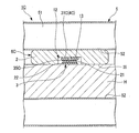
- the sensor unit 6 when the sensor unit 6 is attached to the human body H, the sensor unit 6 is first arranged on the surface of the human body H. Next, a part of the human body H (for example, a wrist or an arm) is passed through the cuff 5 so that the sensor unit 6 is disposed between the human body H and the inner peripheral surface 52 of the cuff 5. Thereafter, the air pressure in the cuff 5 is increased by an air supply unit (not shown) such as an air pump, so that the sensor unit 6 is sandwiched between the cuff 5 and the human body H as shown in FIG.
- the second outer surface 15 opposite to the first outer surface 11 of the housing 2 of the sensor unit 6 contacts the inner peripheral surface 52 of the cuff 5.
- the sensor unit 6 is pressed against the human body H by the air pressure of the cuff 5 (hereinafter referred to as cuff pressure) so that the first outer surface 11 of the housing 2 contacts the human body H.
- cuff pressure the air pressure of the cuff 5
- the sensor unit 3 When the sensor unit 6 is pressed against the human body H by the cuff pressure, the sensor unit 3 is placed on the housing 2 so that the whole of the sensor unit 3 slightly enters the recess 12 (so that the sensor unit 3 approaches the bottom surface 13 side of the recess 12). It is displaced with respect to it. That is, the sensor unit 3 is located in the sealed recess 12. Since the displacement of the sensor unit 3 is limited by the first outer surface 11 of the housing 2, the cuff pressure acting on the sensor unit 3 is relieved. Therefore, it is possible to prevent the electret sensor 21 of the sensor unit 3 from being compressed with excessive pressure in the thickness direction, and to prevent the sensitivity of the electret sensor 21 from being lowered.
- the sensor unit 3 is pressed against the human body H by the elastic force of the elastic film 31.
- the sensor unit 3 can be pressed against the human body H with an appropriate elastic force (an elastic force that does not decrease the sensitivity of the electret sensor 21). Since the sensor unit 3 is pressed against the human body H, the vibration of the human body H (for example, vibration accompanying blood flow) can be directly detected without passing through air (that is, without converting to sound).
- the vibration transmission spacer 22 of the sensor unit 3 is sandwiched between the electret sensor 21 and the human body H and elastically deformed.
- the vibration of the human body H is transmitted to the electret sensor 21 via the vibration transmission spacer 22 in contact with the human body H.
- the cuff 5 can block blood vessels inside the human body H. That is, the biosensor 1 of the first embodiment can be used as a sphygmomanometer that measures blood pressure. Specifically, the blood pressure can be measured by detecting the Korotkoff sound by vibration by the sensor unit 3 while changing the cuff pressure. Since the first outer surface 11 of the housing 2 excluding the opening of the recess 12 and the inner peripheral surface 52 of the cuff 5 are pressed against the human body H by the cuff pressure, the sensor unit 6 has an influence on blood pressure measurement. Absent.
- the concave portion 12 of the housing 2 is sealed from the outside, and the concave portion 12 in which the sensor unit 3 is sealed. Arranged inside. That is, the sensor unit 3 is disposed in a sealed space surrounded by the concave portion 12 of the housing 2 having sound insulation and the human body H.
- the human body H also has a certain weight (large specific gravity), it is difficult for the sound from the outside to pass through the human body H. Therefore, it is possible to suppress external sound from reaching the sensor unit 3. Thereby, the noise contained in the signal output from the sensor part 3 according to the vibration of the human body H can be reduced, and the vibration of the living body can be accurately grasped.
- the vibration transmission spacer 22 interposed between the electret sensor 21 and the human body H is pressed against and closely contacts the human body H by the elastic force of the elastic film 31. Thereby, the vibration of the human body H can be easily transmitted to the electret sensor 21 via the vibration transmission spacer 22. Furthermore, since the vibration transmission spacer 22 has mechanical properties close to that of the human body H, vibration of the human body H is transmitted to the electret sensor 21 with almost no attenuation. Therefore, the vibration of the human body H can be accurately detected by the electret sensor 21.
- the vibration transmission spacer 22 has elasticity, it can follow the change in the surface shape of the human body H. Even if the surface of the human body H is uneven, the vibration transmitting spacer 22 is deformed to absorb the unevenness of the surface of the human body H. For this reason, it can suppress that a big shape change arises in the electret sensor 21.
- FIG. 1 A diagrammatic representation of the vibration transmission spacer 22.
- the biosensor 1 In the biosensor 1 according to the first embodiment, at least a partial space on the bottom surface 13 side of the recess 12 is sealed from the outside by the elastic film 31, and air existing in the partial space of the recess 12 is an air spring. Configure. Therefore, an elastic force can be applied to the sensor unit 3 by the air spring formed in the recess 12 of the housing 2 in accordance with the displacement of the sensor unit 3 in the opening direction of the recess 12. For this reason, even if the elastic force of the elastic film 31 itself is small, a sufficient elastic force can be applied to the sensor unit 3.
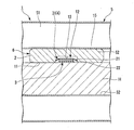
- the biosensor 1B of the second embodiment includes a housing 2B, a sensor unit 3B, an elastic unit 4, and a cuff 5 as in the first embodiment.
- the housing 2 ⁇ / b> B of the second embodiment has a protruding wall portion 16 ⁇ / b> B formed in an annular shape that protrudes from the edge of the opening of the recess 12.
- the overhanging wall portion 16 ⁇ / b> B covers a part of the opening of the recess 12. Thereby, the space in the recessed part 12 is connected outside through the hole 17B of the overhanging wall part 16B.
- the overhanging wall portion 16B is formed integrally with other parts of the housing 2B and has the same sound insulation as the other parts of the housing 2B.
- the overhanging wall portion 16B forms the first outer surface 11 of the housing 2B together with other parts of the housing 2B.
- the overhanging wall portion 16 ⁇ / b> B faces the bottom surface 13 of the recess 12.
- the sensor unit 3B of the second embodiment includes a main body 24B and a protrusion 25B.
- the main body 24B is disposed in the recess 12 and is formed to be larger than the hole 17B of the overhanging wall 16B as viewed from the first outer surface 11 side of the housing 2B. For this reason, the main body 24 ⁇ / b> B does not come out of the recess 12.
- the protruding portion 25B protrudes integrally from the main body portion 24B and is inserted into the hole 17B of the overhanging wall portion 16B. That is, the protrusion 25B is formed to be smaller than the hole 17B of the overhanging wall 16B when viewed from the first outer surface 11 side of the housing 2B.
- the electret sensor 21 of the sensor unit 3B constitutes a part of the main body 24B described above. Further, the vibration transmission spacer 22 of the sensor unit 3B constitutes a part of the protrusion 25B described above. That is, the size of the vibration transmission spacer 22 viewed from the first outer surface 11 side of the housing 2 ⁇ / b> B is smaller than that of the electret sensor 21. Furthermore, the sensor unit 3B includes an adapter 26B that is provided between the electret sensor 21 and the vibration transmission spacer 22 and constitutes a part of the main body 24B and the protrusion 25B. The adapter 26B only needs to have such a high rigidity that it does not bend and deform.
- the adapter 26 ⁇ / b> B only needs to be configured to transmit vibration of the human body H from the vibration transmission spacer 22 to the electret sensor 21.
- the position of the sensor unit 3B with respect to the housing 2B (particularly the position in the opening direction of the recess 12) is the same as in the first embodiment.
- the biosensor 1B configured as described above can be attached to the human body H similarly to the first embodiment. As shown in FIG. 5, in the state where the biosensor 1 ⁇ / b> B is attached to the human body H, the hole 17 ⁇ / b> B of the overhanging wall portion 16 ⁇ / b> B of the housing 2 ⁇ / b> B is blocked by the human body H. Thereby, the recessed part 12 is sealed with respect to the exterior.
- the sensor unit 6B including the housing 2B, the sensor unit 3B, and the elastic unit 4 is pressed against the human body H by the cuff pressure (air pressure of the cuff 5)
- the sensor unit 3B Is displaced with respect to the housing 2B so as to enter the space in the recess 12 including the hole 17B of the overhanging wall portion 16B, and is positioned in the sealed recess 12.
- the protrusion 25 ⁇ / b> B (vibration transmission spacer 22) of the sensor unit 3 ⁇ / b> B is pressed against the human body H by the elastic force of the elastic film 31. In this state, the vibration of the human body H is transmitted to the electret sensor 21 via the vibration transmission spacer 22 and the adapter 26B that are in contact with the human body H.
- the biosensor 1B according to the second embodiment has the same effects as those of the first embodiment. Moreover, in the biosensor 1B according to the second embodiment, a part of the opening of the recess 12 is covered with the overhanging wall portion 16B. That is, the opening of the recess 12 is substantially reduced. Further, a part of the main body 24B of the sensor unit 3B is covered with the overhanging wall 16B. For this reason, it can suppress effectively that the sound from the outside enters into the recessed part 12, and reaches
- the noise contained in the signal output from the sensor unit 3B (electret sensor 21) according to the vibration of the human body H can be further reduced.
- the opening of the recess 12 is substantially reduced, so that the human body H can be prevented from entering the recess 12 even when the sensor unit 6B is pressed against the human body H.
- variation in the size of the human body H entering the recess 12 can be suppressed.
- the main body 24B of the sensor unit 3B may be configured by the electret sensor 21 and the adapter 26B, and the protrusion 25B of the sensor unit 3B may be configured by only the vibration transmission spacer 22.
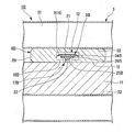
- the biological sensor 1 ⁇ / b> C of the third embodiment includes a housing 2, a sensor unit 3, an elastic unit 4 ⁇ / b> C, and a cuff 5, as in the first embodiment.
- the elastic part 4 ⁇ / b> C of the third embodiment is an elastic spacer 31 ⁇ / b> C interposed between the sensor part 3 and the bottom surface 13 of the recess 12 of the housing 2.
- the elastic spacer 31 ⁇ / b> C is made of a gel-like material, for example, like the vibration transmission spacer 22.
- the elastic spacer 31 ⁇ / b> C is disposed with a space between the inner surface 14 of the recess 12.
- the elastic spacer 31C is formed in an annular shape in a plan view as viewed from the direction in which the recess 12 opens. For this reason, the elastic spacer 31 ⁇ / b> C overlaps the annular region of the bottom surface 13 of the recess 12 and the surface of the sensor unit 3 facing the recess 13 when viewed from the direction in which the recess 12 opens.
- a rigid plate (plate part) 35C is provided between the sensor part 3 and the elastic spacer 31C.
- the rigid plate 35 ⁇ / b> C is disposed so as to be in contact with the entire surface of the sensor unit 3 that faces the bottom surface 13 of the recess 12.
- the rigid plate 35C is made of metal, for example, and has higher rigidity than the vibration transmission spacer 22 and the elastic spacer 31C. For this reason, the rigid plate 35C is not easily deformed even if the vibration transmission spacer 22 or the elastic spacer 31C is deformed.
- the biosensor 1C configured as described above can be attached to the human body H as in the first embodiment. As shown in FIG. 7, in a state where the biosensor 1C is attached to the human body H, the opening of the concave portion 12 of the housing 2 is blocked by the human body H, and the concave portion 12 is sealed from the outside. Similarly to the first embodiment, when the sensor unit 6C including the housing 2, the sensor unit 3, and the elastic unit 4C is pressed against the human body H by the cuff pressure (air pressure of the cuff 5), the sensor unit 3 Is displaced with respect to the housing 2 so as to enter the space in the recess 12, and is positioned in the sealed recess 12.
- the sensor unit 3 is pressed against the human body H by the elastic force of the elastic spacer 31 ⁇ / b> C generated by the elastic spacer 31 ⁇ / b> C being crushed between the sensor unit 3 and the bottom surface 13 of the recess 12.
- the biosensor 1C according to the third embodiment has the same effects as those of the first embodiment.
- the sensor unit 3 is pressed against the human body H by the elastic force of the elastic spacer 31C. For this reason, an elastic force can be applied to the sensor unit 3 without using the elastic film 31 as in the first and second embodiments.
- the vibration transmission spacer 22 and the elastic spacer 31 ⁇ / b> C can be provided with a common material, and thus diversification of members can be suppressed.
- a rigid plate 35C is provided between the sensor unit 3 and the elastic spacer 31C. For this reason, even if the elastic spacer 31C is pressed against only a part of the rigid plate 35C by the elastic force, the elastic force of the elastic spacer 31C acts uniformly on the entire surface of the sensor unit 3 facing the bottom surface 13 of the recess 12. It becomes easy. Thereby, the sensitivity in the sensor part 3 (especially electret sensor 21) can further be improved.
- the elastic spacer 31C is crushed when the sensor unit 3 is displaced so as to approach the bottom surface 13 of the recess 12, but there is a space between the outer side and the inner side of the elastic spacer 31C. Is formed. Since this space is a space that allows deformation of the elastic spacer 31C, it is possible to secure a wide area for the elastic spacer 31C to escape. Further, the elastic spacer 31C can secure a region that can be uniformly deformed toward both the outside and the inside.
- the elastic spacer 31C may be formed in an arbitrary shape.
- the elastic spacer 31 ⁇ / b> C may be formed in a shape overlapping the entire surface of the sensor unit 3 facing the bottom surface 13 of the recess 12 in the opening direction of the recess 12.
- the rigid plate 35C may not be provided.
- the elastic spacer 31C and the rigid plate 35C of the third embodiment can also be applied to the biosensor 1B of the second embodiment.
- casing 2B and sensor part 3B of 2nd Embodiment are applicable to the biosensor 1C of 3rd Embodiment.
- the biosensor 1 ⁇ / b> D of the fourth embodiment includes a sensor unit 6 including a housing 2, a sensor unit 3, and an elastic unit 4, and a cuff 5, as in the first embodiment. Prepare.
- the sensor unit 6 is provided integrally with the cuff 5.
- the sensor unit 6 may be provided on the cuff 5 so that at least the first outer surface 11 of the housing 2 faces the surface of the human body H together with the inner peripheral surface 52 of the cuff 5.
- the sensor unit 6 is provided to the cuff 5 so that the housing 2 closes a through hole 54 ⁇ / b> D formed in the film portion 53 ⁇ / b> D on the inner peripheral side of the cuff 5. That is, the housing 2 constitutes a part of the cuff 5.
- the first outer surface 11 of the housing 2 is positioned higher than the inner peripheral surface 52 of the cuff 5.
- the first outer surface 11 of the housing 2 is flush with the inner peripheral surface 52 of the cuff 5. It may be positioned so that no step is generated between the peripheral surface 52 and the peripheral surface 52.
- the biosensor 1D according to the fourth embodiment has the same effects as those of the first embodiment.
- the sensor unit 6 is provided integrally with the cuff 5.
- the sensor unit 6 (especially the sensor part 3) can be positioned with respect to the human body H simultaneously with the positioning of the cuff 5 with respect to the human body H (for example, wrist or arm). That is, it is possible to easily position the sensor unit 3 with respect to the human body H.
- the housing 2 may be fixed to the inner peripheral surface 52 of the cuff 5 by adhesion or the like.
- the configuration of the fourth embodiment can also be applied to the biosensors 1B and 1C of the second and third embodiments.
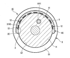
- the biosensor 1 ⁇ / b> E of the fifth embodiment includes a sensor unit 6 ⁇ / b> E including a housing 2 ⁇ / b> E, a sensor unit 3, and an elastic unit 4 and a cuff 5, as in the first embodiment.
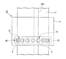
- the housing 2E of the fifth embodiment has a plurality (nine in FIG. 10) of recesses 12 that open to the first outer surface 11.
- One sensor unit 3 is provided for each of the plurality of recesses 12 of the housing 2E.
- the plurality of recesses 12 are arranged at intervals in one direction along the first outer surface 11 of the housing 2E.
- the plurality of recesses 12 may be arranged in two directions orthogonal to each other, for example, along the first outer surface 11 of the housing 2E.
- the housing 2E can be in contact with the surface of the human body H, that is, the first outer surface 11 of the housing 2E is the human body. It is good to be comprised so that it can follow the surface of H.
- the housing 2E may be configured to be able to bend and deform, for example, by being formed of a silicone resin.
- the housing 2E includes, for example, a plurality of housing element portions having a first outer surface 11 and a recess 12 that opens to the first outer surface 11, and the plurality of housing element portions are connected to each other by a connecting portion so as to be rotatable. May be.
- the connecting portion may be a hinge, for example.
- the connecting portion may be formed integrally with the housing element portion using the same material as the housing element portion, for example, and may be formed thinner than the housing element portion so as to bend and deform.
- the biosensor 1E further includes an acquisition unit 7E and a signal processing unit 8E.
- the acquisition unit 7E acquires signals output from the plurality of sensor units 3.
- the output signal from the sensor unit 3 is a signal indicating the vibration of the human body H detected by the sensor unit 3.
- the signal processing unit 8E performs signal processing so as to obtain a desired signal by extracting or synthesizing from the output signals of the plurality of sensor units 3 obtained by the acquisition unit 7E.
- the signal processing unit 8E may compare a plurality of output signals output from the plurality of sensor units 3 and select an output signal having the largest output (amplitude). In this case, the signal processing unit 8E outputs the selected output signal to various external devices.
- the signal processing unit 8E may perform a composite operation on a plurality of output signals output from the plurality of sensor units 3, for example.
- the plurality of output signals are converted according to the distance from the vibration source in the human body H (the brachial artery AR1 passing through the arm portion in FIGS. 10 and 11) to each sensor unit 3. Delayed addition is recommended.
- the signal processing unit 8E determines whether the feature portions (for example, feature amount data obtained by performing cross-correlation analysis) of the plurality of output signals indicating the vibration of the human body H match or the correlation among the feature portions of the output signal. Synthesis is performed by adding the output signals in phase so that the high portions overlap.
- the output signals from the plurality of sensor units 3 may be combined, or the correlation of the characteristic portions of the output signals is high. Only the sensor unit 3 may be selected and combined.
- the biosensor 1E according to the fifth embodiment has the same effects as those of the first embodiment.
- the biosensor 1E according to the fifth embodiment is configured such that the plurality of sensor units 3 are in contact with the human body H. For this reason, even if the positional accuracy of the biosensor 1E with respect to the human body H is low, any one of the sensor units 3 can be positioned near the vibration source of the human body H. Thereby, for example, the vibration of the human body H can be accurately detected by selecting and using the signal indicating the highest output among the output signals from the plurality of sensor units 3. Further, for example, the vibration of the human body H can be detected with high accuracy by combining and calculating the output signals from the plurality of sensor units 3. That is, the S / N ratio (signal-noise ratio) of the signal output from the biosensor 1E can be improved.
- the acquisition unit 7E and the signal processing unit 8E may be configured by a processing device such as a CPU (Central Processing Unit) or a dedicated electronic circuit, for example. Further, the acquisition unit 7E and the signal processing unit 8E may be configured by, for example, separate processing devices and electronic circuits, respectively, or at least a part of them may be configured by a common processing device and electronic circuit, for example. .
- a processing device such as a CPU (Central Processing Unit) or a dedicated electronic circuit, for example.
- the acquisition unit 7E and the signal processing unit 8E may be configured by, for example, separate processing devices and electronic circuits, respectively, or at least a part of them may be configured by a common processing device and electronic circuit, for example. .
- the part where the biosensor is provided may be a part that is a target for detecting vibration of the living body.
- the part where the biosensor is provided may be a part other than the wrist or the arm part, for example, a part such as a human head, torso, ankle, or leg.
- the sensor body (sensor unit) that detects the vibration of the living body is not limited to the electret sensor, and may be an arbitrary sensor such as a vibration detection sensor such as a piezo, or another pressure sensor. .
Landscapes
- Health & Medical Sciences (AREA)
- Life Sciences & Earth Sciences (AREA)
- Biomedical Technology (AREA)
- Heart & Thoracic Surgery (AREA)
- Veterinary Medicine (AREA)
- Physics & Mathematics (AREA)
- Vascular Medicine (AREA)
- Biophysics (AREA)
- Pathology (AREA)
- Engineering & Computer Science (AREA)
- Public Health (AREA)
- Cardiology (AREA)
- Medical Informatics (AREA)
- Molecular Biology (AREA)
- Surgery (AREA)
- Animal Behavior & Ethology (AREA)
- General Health & Medical Sciences (AREA)
- Ophthalmology & Optometry (AREA)
- Physiology (AREA)
- Measuring Pulse, Heart Rate, Blood Pressure Or Blood Flow (AREA)
- Measuring And Recording Apparatus For Diagnosis (AREA)
Applications Claiming Priority (2)
| Application Number | Priority Date | Filing Date | Title |
|---|---|---|---|
| JP2018-028875 | 2018-02-21 | ||
| JP2018028875A JP2019141349A (ja) | 2018-02-21 | 2018-02-21 | 生体センサ |
Publications (1)
| Publication Number | Publication Date |
|---|---|
| WO2019163515A1 true WO2019163515A1 (ja) | 2019-08-29 |
Family
ID=67688067
Family Applications (1)
| Application Number | Title | Priority Date | Filing Date |
|---|---|---|---|
| PCT/JP2019/004243 Ceased WO2019163515A1 (ja) | 2018-02-21 | 2019-02-06 | 生体センサ |
Country Status (2)
| Country | Link |
|---|---|
| JP (1) | JP2019141349A (enExample) |
| WO (1) | WO2019163515A1 (enExample) |
Citations (7)
| Publication number | Priority date | Publication date | Assignee | Title |
|---|---|---|---|---|
| JPS5459786U (enExample) * | 1977-10-04 | 1979-04-25 | ||
| JPH07116138A (ja) * | 1993-10-26 | 1995-05-09 | Matsushita Electric Works Ltd | 脈拍検出方法及びその装置 |
| JP2005218500A (ja) * | 2004-02-03 | 2005-08-18 | Casio Comput Co Ltd | 手首装着型脈拍測定装置 |
| JP2009066356A (ja) * | 2007-09-18 | 2009-04-02 | Citizen Holdings Co Ltd | 生体情報測定装置 |
| JP2009226024A (ja) * | 2008-03-24 | 2009-10-08 | Citizen Holdings Co Ltd | センサユニット |
| US20170215748A1 (en) * | 2014-07-29 | 2017-08-03 | Lg Electronics Inc. | Hemadynamometer and mobile terminal including the same |
| JP2019010415A (ja) * | 2017-06-30 | 2019-01-24 | ヤマハ株式会社 | 電子血圧計、血圧測定方法、及び電子聴診器 |
-
2018
- 2018-02-21 JP JP2018028875A patent/JP2019141349A/ja active Pending
-
2019
- 2019-02-06 WO PCT/JP2019/004243 patent/WO2019163515A1/ja not_active Ceased
Patent Citations (7)
| Publication number | Priority date | Publication date | Assignee | Title |
|---|---|---|---|---|
| JPS5459786U (enExample) * | 1977-10-04 | 1979-04-25 | ||
| JPH07116138A (ja) * | 1993-10-26 | 1995-05-09 | Matsushita Electric Works Ltd | 脈拍検出方法及びその装置 |
| JP2005218500A (ja) * | 2004-02-03 | 2005-08-18 | Casio Comput Co Ltd | 手首装着型脈拍測定装置 |
| JP2009066356A (ja) * | 2007-09-18 | 2009-04-02 | Citizen Holdings Co Ltd | 生体情報測定装置 |
| JP2009226024A (ja) * | 2008-03-24 | 2009-10-08 | Citizen Holdings Co Ltd | センサユニット |
| US20170215748A1 (en) * | 2014-07-29 | 2017-08-03 | Lg Electronics Inc. | Hemadynamometer and mobile terminal including the same |
| JP2019010415A (ja) * | 2017-06-30 | 2019-01-24 | ヤマハ株式会社 | 電子血圧計、血圧測定方法、及び電子聴診器 |
Also Published As
| Publication number | Publication date |
|---|---|
| JP2019141349A (ja) | 2019-08-29 |
Similar Documents
| Publication | Publication Date | Title |
|---|---|---|
| US11311238B2 (en) | Attachable sensing pod comprising a piezoelectric unit | |
| US10548492B2 (en) | Pressure sensor | |
| EP3443894B1 (en) | Pulse wave detection device and biological information measuring device | |
| JP7280246B2 (ja) | 子宮収縮及び胎児心拍数を測定する装置 | |
| US20200100687A1 (en) | Pulse wave measurement device and blood pressure measurement device | |
| JP5733240B2 (ja) | 振動検出装置 | |
| JP6240581B2 (ja) | 脈波センサユニット | |
| WO2019163515A1 (ja) | 生体センサ | |
| JP6612682B2 (ja) | 圧力検出装置および生体情報計測システム | |
| JP3716326B2 (ja) | 脈圧測定装置 | |
| JPH10309272A (ja) | 心音検出装置 | |
| CN210354696U (zh) | 生物振动信号监测装置 | |
| JP2023543009A (ja) | 中心血圧の推定 | |
| JP2011010913A (ja) | 振動センサ | |
| JP2000041960A (ja) | 腕携帯機器 | |
| CN219421025U (zh) | 骨声纹传感器及电子产品 | |
| JP2025120831A (ja) | 振動検出装置、心拍センサ、ウェアラブルデバイス、及び振動検出方法 | |
| CN119214678A (zh) | 穿戴设备 | |
| JP6117756B2 (ja) | 脈波センサユニット | |
| WO2024089976A1 (ja) | 血圧計、血圧測定方法およびコロトコフ音検出装置 | |
| WO2023162992A1 (ja) | チェストピース及び聴診器 | |
| ITUA20163678A1 (it) | Dispositivo di monitoraggio fisiologico | |
| JP6345060B2 (ja) | 脈波センサユニット | |
| WO2024256437A1 (en) | Health monitoring arrangement | |
| JP2006230911A (ja) | 超音波診断装置および保持装置 |
Legal Events
| Date | Code | Title | Description |
|---|---|---|---|
| 121 | Ep: the epo has been informed by wipo that ep was designated in this application |
Ref document number: 19757036 Country of ref document: EP Kind code of ref document: A1 |
|
| NENP | Non-entry into the national phase |
Ref country code: DE |
|
| 122 | Ep: pct application non-entry in european phase |
Ref document number: 19757036 Country of ref document: EP Kind code of ref document: A1 |