WO2019159723A1 - 車両制御装置 - Google Patents
車両制御装置 Download PDFInfo
- Publication number
- WO2019159723A1 WO2019159723A1 PCT/JP2019/003716 JP2019003716W WO2019159723A1 WO 2019159723 A1 WO2019159723 A1 WO 2019159723A1 JP 2019003716 W JP2019003716 W JP 2019003716W WO 2019159723 A1 WO2019159723 A1 WO 2019159723A1
- Authority
- WO
- WIPO (PCT)
- Prior art keywords
- vehicle
- speed
- road surface
- traveling
- surface state
- Prior art date
Links
Images


Classifications
-
- B—PERFORMING OPERATIONS; TRANSPORTING
- B60—VEHICLES IN GENERAL
- B60W—CONJOINT CONTROL OF VEHICLE SUB-UNITS OF DIFFERENT TYPE OR DIFFERENT FUNCTION; CONTROL SYSTEMS SPECIALLY ADAPTED FOR HYBRID VEHICLES; ROAD VEHICLE DRIVE CONTROL SYSTEMS FOR PURPOSES NOT RELATED TO THE CONTROL OF A PARTICULAR SUB-UNIT
- B60W30/00—Purposes of road vehicle drive control systems not related to the control of a particular sub-unit, e.g. of systems using conjoint control of vehicle sub-units, or advanced driver assistance systems for ensuring comfort, stability and safety or drive control systems for propelling or retarding the vehicle
- B60W30/08—Active safety systems predicting or avoiding probable or impending collision or attempting to minimise its consequences
- B60W30/095—Predicting travel path or likelihood of collision
- B60W30/0953—Predicting travel path or likelihood of collision the prediction being responsive to vehicle dynamic parameters
-
- B—PERFORMING OPERATIONS; TRANSPORTING
- B60—VEHICLES IN GENERAL
- B60W—CONJOINT CONTROL OF VEHICLE SUB-UNITS OF DIFFERENT TYPE OR DIFFERENT FUNCTION; CONTROL SYSTEMS SPECIALLY ADAPTED FOR HYBRID VEHICLES; ROAD VEHICLE DRIVE CONTROL SYSTEMS FOR PURPOSES NOT RELATED TO THE CONTROL OF A PARTICULAR SUB-UNIT
- B60W30/00—Purposes of road vehicle drive control systems not related to the control of a particular sub-unit, e.g. of systems using conjoint control of vehicle sub-units, or advanced driver assistance systems for ensuring comfort, stability and safety or drive control systems for propelling or retarding the vehicle
- B60W30/18—Propelling the vehicle
- B60W30/18009—Propelling the vehicle related to particular drive situations
-
- B—PERFORMING OPERATIONS; TRANSPORTING
- B60—VEHICLES IN GENERAL
- B60T—VEHICLE BRAKE CONTROL SYSTEMS OR PARTS THEREOF; BRAKE CONTROL SYSTEMS OR PARTS THEREOF, IN GENERAL; ARRANGEMENT OF BRAKING ELEMENTS ON VEHICLES IN GENERAL; PORTABLE DEVICES FOR PREVENTING UNWANTED MOVEMENT OF VEHICLES; VEHICLE MODIFICATIONS TO FACILITATE COOLING OF BRAKES
- B60T7/00—Brake-action initiating means
- B60T7/12—Brake-action initiating means for automatic initiation; for initiation not subject to will of driver or passenger
-
- B—PERFORMING OPERATIONS; TRANSPORTING
- B60—VEHICLES IN GENERAL
- B60T—VEHICLE BRAKE CONTROL SYSTEMS OR PARTS THEREOF; BRAKE CONTROL SYSTEMS OR PARTS THEREOF, IN GENERAL; ARRANGEMENT OF BRAKING ELEMENTS ON VEHICLES IN GENERAL; PORTABLE DEVICES FOR PREVENTING UNWANTED MOVEMENT OF VEHICLES; VEHICLE MODIFICATIONS TO FACILITATE COOLING OF BRAKES
- B60T8/00—Arrangements for adjusting wheel-braking force to meet varying vehicular or ground-surface conditions, e.g. limiting or varying distribution of braking force
- B60T8/17—Using electrical or electronic regulation means to control braking
- B60T8/172—Determining control parameters used in the regulation, e.g. by calculations involving measured or detected parameters
-
- B—PERFORMING OPERATIONS; TRANSPORTING
- B60—VEHICLES IN GENERAL
- B60W—CONJOINT CONTROL OF VEHICLE SUB-UNITS OF DIFFERENT TYPE OR DIFFERENT FUNCTION; CONTROL SYSTEMS SPECIALLY ADAPTED FOR HYBRID VEHICLES; ROAD VEHICLE DRIVE CONTROL SYSTEMS FOR PURPOSES NOT RELATED TO THE CONTROL OF A PARTICULAR SUB-UNIT
- B60W10/00—Conjoint control of vehicle sub-units of different type or different function
- B60W10/18—Conjoint control of vehicle sub-units of different type or different function including control of braking systems
-
- B—PERFORMING OPERATIONS; TRANSPORTING
- B60—VEHICLES IN GENERAL
- B60W—CONJOINT CONTROL OF VEHICLE SUB-UNITS OF DIFFERENT TYPE OR DIFFERENT FUNCTION; CONTROL SYSTEMS SPECIALLY ADAPTED FOR HYBRID VEHICLES; ROAD VEHICLE DRIVE CONTROL SYSTEMS FOR PURPOSES NOT RELATED TO THE CONTROL OF A PARTICULAR SUB-UNIT
- B60W10/00—Conjoint control of vehicle sub-units of different type or different function
- B60W10/20—Conjoint control of vehicle sub-units of different type or different function including control of steering systems
-
- B—PERFORMING OPERATIONS; TRANSPORTING
- B60—VEHICLES IN GENERAL
- B60W—CONJOINT CONTROL OF VEHICLE SUB-UNITS OF DIFFERENT TYPE OR DIFFERENT FUNCTION; CONTROL SYSTEMS SPECIALLY ADAPTED FOR HYBRID VEHICLES; ROAD VEHICLE DRIVE CONTROL SYSTEMS FOR PURPOSES NOT RELATED TO THE CONTROL OF A PARTICULAR SUB-UNIT
- B60W30/00—Purposes of road vehicle drive control systems not related to the control of a particular sub-unit, e.g. of systems using conjoint control of vehicle sub-units, or advanced driver assistance systems for ensuring comfort, stability and safety or drive control systems for propelling or retarding the vehicle
- B60W30/08—Active safety systems predicting or avoiding probable or impending collision or attempting to minimise its consequences
- B60W30/09—Taking automatic action to avoid collision, e.g. braking and steering
-
- B—PERFORMING OPERATIONS; TRANSPORTING
- B60—VEHICLES IN GENERAL
- B60W—CONJOINT CONTROL OF VEHICLE SUB-UNITS OF DIFFERENT TYPE OR DIFFERENT FUNCTION; CONTROL SYSTEMS SPECIALLY ADAPTED FOR HYBRID VEHICLES; ROAD VEHICLE DRIVE CONTROL SYSTEMS FOR PURPOSES NOT RELATED TO THE CONTROL OF A PARTICULAR SUB-UNIT
- B60W30/00—Purposes of road vehicle drive control systems not related to the control of a particular sub-unit, e.g. of systems using conjoint control of vehicle sub-units, or advanced driver assistance systems for ensuring comfort, stability and safety or drive control systems for propelling or retarding the vehicle
- B60W30/08—Active safety systems predicting or avoiding probable or impending collision or attempting to minimise its consequences
- B60W30/095—Predicting travel path or likelihood of collision
- B60W30/0956—Predicting travel path or likelihood of collision the prediction being responsive to traffic or environmental parameters
-
- B—PERFORMING OPERATIONS; TRANSPORTING
- B60—VEHICLES IN GENERAL
- B60W—CONJOINT CONTROL OF VEHICLE SUB-UNITS OF DIFFERENT TYPE OR DIFFERENT FUNCTION; CONTROL SYSTEMS SPECIALLY ADAPTED FOR HYBRID VEHICLES; ROAD VEHICLE DRIVE CONTROL SYSTEMS FOR PURPOSES NOT RELATED TO THE CONTROL OF A PARTICULAR SUB-UNIT
- B60W30/00—Purposes of road vehicle drive control systems not related to the control of a particular sub-unit, e.g. of systems using conjoint control of vehicle sub-units, or advanced driver assistance systems for ensuring comfort, stability and safety or drive control systems for propelling or retarding the vehicle
- B60W30/18—Propelling the vehicle
- B60W30/18009—Propelling the vehicle related to particular drive situations
- B60W30/18163—Lane change; Overtaking manoeuvres
-
- B—PERFORMING OPERATIONS; TRANSPORTING
- B60—VEHICLES IN GENERAL
- B60W—CONJOINT CONTROL OF VEHICLE SUB-UNITS OF DIFFERENT TYPE OR DIFFERENT FUNCTION; CONTROL SYSTEMS SPECIALLY ADAPTED FOR HYBRID VEHICLES; ROAD VEHICLE DRIVE CONTROL SYSTEMS FOR PURPOSES NOT RELATED TO THE CONTROL OF A PARTICULAR SUB-UNIT
- B60W40/00—Estimation or calculation of non-directly measurable driving parameters for road vehicle drive control systems not related to the control of a particular sub unit, e.g. by using mathematical models
- B60W40/02—Estimation or calculation of non-directly measurable driving parameters for road vehicle drive control systems not related to the control of a particular sub unit, e.g. by using mathematical models related to ambient conditions
- B60W40/06—Road conditions
- B60W40/068—Road friction coefficient
-
- G—PHYSICS
- G08—SIGNALLING
- G08G—TRAFFIC CONTROL SYSTEMS
- G08G1/00—Traffic control systems for road vehicles
- G08G1/09—Arrangements for giving variable traffic instructions
-
- G—PHYSICS
- G08—SIGNALLING
- G08G—TRAFFIC CONTROL SYSTEMS
- G08G1/00—Traffic control systems for road vehicles
- G08G1/16—Anti-collision systems
-
- B—PERFORMING OPERATIONS; TRANSPORTING
- B60—VEHICLES IN GENERAL
- B60W—CONJOINT CONTROL OF VEHICLE SUB-UNITS OF DIFFERENT TYPE OR DIFFERENT FUNCTION; CONTROL SYSTEMS SPECIALLY ADAPTED FOR HYBRID VEHICLES; ROAD VEHICLE DRIVE CONTROL SYSTEMS FOR PURPOSES NOT RELATED TO THE CONTROL OF A PARTICULAR SUB-UNIT
- B60W2520/00—Input parameters relating to overall vehicle dynamics
- B60W2520/10—Longitudinal speed
-
- B—PERFORMING OPERATIONS; TRANSPORTING
- B60—VEHICLES IN GENERAL
- B60W—CONJOINT CONTROL OF VEHICLE SUB-UNITS OF DIFFERENT TYPE OR DIFFERENT FUNCTION; CONTROL SYSTEMS SPECIALLY ADAPTED FOR HYBRID VEHICLES; ROAD VEHICLE DRIVE CONTROL SYSTEMS FOR PURPOSES NOT RELATED TO THE CONTROL OF A PARTICULAR SUB-UNIT
- B60W2552/00—Input parameters relating to infrastructure
- B60W2552/40—Coefficient of friction
-
- B—PERFORMING OPERATIONS; TRANSPORTING
- B60—VEHICLES IN GENERAL
- B60W—CONJOINT CONTROL OF VEHICLE SUB-UNITS OF DIFFERENT TYPE OR DIFFERENT FUNCTION; CONTROL SYSTEMS SPECIALLY ADAPTED FOR HYBRID VEHICLES; ROAD VEHICLE DRIVE CONTROL SYSTEMS FOR PURPOSES NOT RELATED TO THE CONTROL OF A PARTICULAR SUB-UNIT
- B60W2554/00—Input parameters relating to objects
- B60W2554/40—Dynamic objects, e.g. animals, windblown objects
- B60W2554/404—Characteristics
- B60W2554/4041—Position
-
- B—PERFORMING OPERATIONS; TRANSPORTING
- B60—VEHICLES IN GENERAL
- B60W—CONJOINT CONTROL OF VEHICLE SUB-UNITS OF DIFFERENT TYPE OR DIFFERENT FUNCTION; CONTROL SYSTEMS SPECIALLY ADAPTED FOR HYBRID VEHICLES; ROAD VEHICLE DRIVE CONTROL SYSTEMS FOR PURPOSES NOT RELATED TO THE CONTROL OF A PARTICULAR SUB-UNIT
- B60W2554/00—Input parameters relating to objects
- B60W2554/80—Spatial relation or speed relative to objects
- B60W2554/802—Longitudinal distance
-
- B—PERFORMING OPERATIONS; TRANSPORTING
- B60—VEHICLES IN GENERAL
- B60W—CONJOINT CONTROL OF VEHICLE SUB-UNITS OF DIFFERENT TYPE OR DIFFERENT FUNCTION; CONTROL SYSTEMS SPECIALLY ADAPTED FOR HYBRID VEHICLES; ROAD VEHICLE DRIVE CONTROL SYSTEMS FOR PURPOSES NOT RELATED TO THE CONTROL OF A PARTICULAR SUB-UNIT
- B60W2556/00—Input parameters relating to data
- B60W2556/45—External transmission of data to or from the vehicle
- B60W2556/65—Data transmitted between vehicles
-
- B—PERFORMING OPERATIONS; TRANSPORTING
- B60—VEHICLES IN GENERAL
- B60W—CONJOINT CONTROL OF VEHICLE SUB-UNITS OF DIFFERENT TYPE OR DIFFERENT FUNCTION; CONTROL SYSTEMS SPECIALLY ADAPTED FOR HYBRID VEHICLES; ROAD VEHICLE DRIVE CONTROL SYSTEMS FOR PURPOSES NOT RELATED TO THE CONTROL OF A PARTICULAR SUB-UNIT
- B60W2710/00—Output or target parameters relating to a particular sub-units
- B60W2710/18—Braking system
-
- B—PERFORMING OPERATIONS; TRANSPORTING
- B60—VEHICLES IN GENERAL
- B60W—CONJOINT CONTROL OF VEHICLE SUB-UNITS OF DIFFERENT TYPE OR DIFFERENT FUNCTION; CONTROL SYSTEMS SPECIALLY ADAPTED FOR HYBRID VEHICLES; ROAD VEHICLE DRIVE CONTROL SYSTEMS FOR PURPOSES NOT RELATED TO THE CONTROL OF A PARTICULAR SUB-UNIT
- B60W2710/00—Output or target parameters relating to a particular sub-units
- B60W2710/20—Steering systems
-
- B—PERFORMING OPERATIONS; TRANSPORTING
- B60—VEHICLES IN GENERAL
- B60W—CONJOINT CONTROL OF VEHICLE SUB-UNITS OF DIFFERENT TYPE OR DIFFERENT FUNCTION; CONTROL SYSTEMS SPECIALLY ADAPTED FOR HYBRID VEHICLES; ROAD VEHICLE DRIVE CONTROL SYSTEMS FOR PURPOSES NOT RELATED TO THE CONTROL OF A PARTICULAR SUB-UNIT
- B60W2720/00—Output or target parameters relating to overall vehicle dynamics
- B60W2720/10—Longitudinal speed
-
- B—PERFORMING OPERATIONS; TRANSPORTING
- B60—VEHICLES IN GENERAL
- B60W—CONJOINT CONTROL OF VEHICLE SUB-UNITS OF DIFFERENT TYPE OR DIFFERENT FUNCTION; CONTROL SYSTEMS SPECIALLY ADAPTED FOR HYBRID VEHICLES; ROAD VEHICLE DRIVE CONTROL SYSTEMS FOR PURPOSES NOT RELATED TO THE CONTROL OF A PARTICULAR SUB-UNIT
- B60W2754/00—Output or target parameters relating to objects
- B60W2754/10—Spatial relation or speed relative to objects
- B60W2754/40—Relative lateral speed
-
- B—PERFORMING OPERATIONS; TRANSPORTING
- B60—VEHICLES IN GENERAL
- B60W—CONJOINT CONTROL OF VEHICLE SUB-UNITS OF DIFFERENT TYPE OR DIFFERENT FUNCTION; CONTROL SYSTEMS SPECIALLY ADAPTED FOR HYBRID VEHICLES; ROAD VEHICLE DRIVE CONTROL SYSTEMS FOR PURPOSES NOT RELATED TO THE CONTROL OF A PARTICULAR SUB-UNIT
- B60W2754/00—Output or target parameters relating to objects
- B60W2754/10—Spatial relation or speed relative to objects
- B60W2754/50—Relative longitudinal speed
Definitions
- the present invention relates to a vehicle control device, and more particularly, to a vehicle control device that controls traveling of a vehicle.
- Patent Document 1 Japanese Patent Laying-Open No. 2006-218935
- Patent Document 1 describes a vehicle travel support device.
- this vehicle travel support device when an object in the traveling direction of the host vehicle is detected, it is predicted whether a safe distance is secured when the object is closest to the host vehicle, and the safe distance cannot be secured.
- the driving support control is executed.
- the direction of an object is detected, and a safe distance is set according to this direction.
- the control by the vehicle driving support apparatus described in Patent Document 1 is merely for the purpose of avoiding a collision, and overtakes or overtakes the preceding vehicle (parked vehicle) during normal driving of the host vehicle. In some cases, it is not sufficient to avoid collisions. In other words, when overtaking and overtaking the preceding vehicle, it is necessary to maintain a sufficient interval between the preceding vehicle (parked vehicle) without causing anxiety to the driver.
- the applicant sets a speed limit distribution that defines an allowable upper limit value of a plurality of relative speeds around an object such as a preceding vehicle, and automatically avoids exceeding the allowable upper limit value.
- a vehicle control device for controlling the vehicle speed and steering of the vehicle has been developed (International Patent Application JP2016 / 075233). By mounting such a vehicle control device, it is possible to maintain a sufficient distance from the target object even when overtaking and overtaking the target object such as a preceding vehicle, and less likely to cause driver anxiety. Control is successful.
- an object of the present invention is to provide a vehicle control device that can suppress anxiety given to a driver by providing an appropriate interval with a preceding vehicle for various road surface conditions.
- the present invention is a vehicle control device that controls the traveling of a vehicle, and includes a surrounding vehicle detection unit that detects a surrounding vehicle that is traveling around the own vehicle, and a brake of the own vehicle.
- a road surface state estimation unit that estimates a road surface state that affects the braking distance by the vehicle, and a speed distribution that sets a speed limit distribution that defines an upper limit value of an allowable relative speed around the surrounding vehicle detected by the surrounding vehicle detection unit
- the speed distribution setting unit is a road surface state estimation unit.
- the surrounding vehicle detection unit detects a surrounding vehicle running around the own vehicle
- the road surface state estimation unit is configured to affect the braking distance by the brake of the own vehicle. Is estimated.
- the speed distribution setting unit sets a speed limit distribution that defines an upper limit value of an allowable relative speed around the surrounding vehicle detected by the surrounding vehicle detection unit.
- the speed distribution setting unit lowers the upper limit value of the relative speed to be allowed when the road surface state estimation unit estimates that the road surface state is a long braking distance, and the control unit reduces the limit speed distribution. Control the speed and / or steering of the vehicle to be satisfied.
- the upper limit value of the allowable relative speed is reduced, so that it is allowed for the same relative speed.
- the inter-vehicle distance is increased, and the anxiety given to the driver can be suppressed.
- the road surface state estimation unit receives information on the traveling state of the surrounding vehicle transmitted from the surrounding vehicle detected by the surrounding vehicle detection unit, and uses this information to increase the braking distance. It is estimated whether it is a road surface state.
- Japanese Patent No. 5035419 describes a road surface friction coefficient estimation method.
- the vehicle travels based on a lateral force generated by a tire, a slip angle, a tire characteristic curve on a road surface ⁇ , and the like.
- the road surface ⁇ of the road surface is estimated.
- a technique for estimating the road surface ⁇ of a running road surface based on the running state of the vehicle is known.
- information on the traveling state of the surrounding vehicle transmitted from the surrounding vehicle is received, and it is estimated whether or not the road surface state where the braking distance becomes long by using this information.
- the road surface condition can be estimated in detail, and the speed limit distribution can be set appropriately.
- the road surface state is estimated using information about the traveling state transmitted from the surrounding vehicles, not only the state of the road surface on which the host vehicle is currently traveling, but also the state of the front road surface on which the host vehicle is traveling later Even if the road surface condition ahead is changing, it is possible to respond early.
- the road surface state estimation unit is configured to estimate a road surface ⁇ of the traveling lane, and to estimate that the road surface state is a long braking distance when the road surface ⁇ is equal to or less than a predetermined value.
- the speed distribution setting unit reduces the upper limit value of the allowable relative speed in the traveling direction of the host vehicle when it is estimated that the road surface state is a long braking distance.
- the road surface state estimation unit estimates the road surface ⁇ of the traveling lane, and based on this, it is determined whether or not the road surface state increases the braking distance.
- the braking distance can be estimated by the method. Further, when it is estimated that the braking distance becomes long, the upper limit value of the allowable relative speed in the traveling direction is lowered, so that sufficient safety can be ensured even when the braking distance is long.
- the speed distribution setting unit sets the speed limit distribution so that the upper limit value of the allowable relative speed increases as the distance from the surrounding vehicle increases, and the braking distance is increased by the road surface state estimation unit.
- the upper limit value of the relative speed allowed with respect to the distance from the surrounding vehicle is reduced.
- the upper limit value of the relative speed allowed with respect to the distance from the surrounding vehicle is reduced when it is estimated that the road surface state is a long braking distance.
- the relative speed With respect to the relative speed, the distance in the traveling direction between the surrounding vehicle and the host vehicle is increased, and the driver can be provided with a sufficient sense of security even in a road surface state where the braking distance becomes long.
- anxiety given to the driver can be suppressed by providing appropriate intervals with the preceding vehicle for various road surface conditions in which the host vehicle travels.
- FIG. 1 it is a diagram showing a change in the allowable upper limit value of the relative speed when the road surface ⁇ is low.
- FIG. 1 it is a figure which shows the change of the speed limit distribution when road surface (micro
- FIG. 1 is a configuration diagram of the vehicle control device
- FIG. 2 is a control block diagram of the vehicle control device.
- the vehicle control device 100 is configured to provide different driving support controls to a vehicle 1 (see FIG. 3 or the like) on which the vehicle control device 100 is mounted by a plurality of driving support modes.
- the driver can select a desired driving support mode from a plurality of driving support modes.
- the vehicle control device 100 is equipped with a vehicle control arithmetic unit (ECU) 10, a plurality of sensors and switches, a plurality of control systems, and a user input for a driving support mode mounted on the vehicle 1.
- a driver operation unit (not shown) is provided.
- the plurality of sensors and switches include a camera 21 that captures images outside the passenger compartment, a millimeter wave radar 22, a vehicle speed sensor 23 that detects the behavior of the vehicle, a positioning system 24, a navigation system 25, and an inter-vehicle communication system 26.
- the plurality of control systems include an engine control system 31, a brake control system 32, and a steering control system 33.
- the ECU 10 shown in FIG. 1 is configured by a computer having a CPU, a memory for storing various programs, an input / output device, and the like.
- the ECU 10 generates an engine control system 31, a brake control system 32, a steering wheel based on a driving support mode selection signal and a set vehicle speed signal received from a driver operation unit (not shown), and signals received from a plurality of sensors and switches.
- the control system 33 is configured to be able to output request signals for appropriately operating the engine system, the brake system, and the steering system, respectively.
- the camera 21 images the front of the vehicle 1 and outputs the captured image data. Based on the image data, the ECU 10 detects objects (for example, vehicles, pedestrians, roads, lane markings (lane boundaries, white lines, yellow lines), traffic signals, traffic signs, stop lines, intersections, preceding vehicles, obstacles, etc. ).
- objects for example, vehicles, pedestrians, roads, lane markings (lane boundaries, white lines, yellow lines), traffic signals, traffic signs, stop lines, intersections, preceding vehicles, obstacles, etc.
- a vehicle exterior camera that captures images of the side and rear of the vehicle 1 can be provided.
- operator during driving can also be provided in a vehicle.
- the millimeter wave radar 22 is a measuring device that measures the position and speed of an object (particularly, a preceding vehicle, a parked vehicle, a pedestrian, an obstacle, etc.), and transmits radio waves (transmitted waves) toward the front of the vehicle 1. Then, the reflected wave generated by reflecting the transmission wave by the object is received. The millimeter wave radar 22 measures the distance between the vehicle 1 and the object (for example, the inter-vehicle distance) and the relative speed of the object with respect to the vehicle 1 based on the transmitted wave and the received wave.
- the millimeter wave radar 22 includes a front radar that detects an object in front of the vehicle 1, a side radar that detects an object of a side object, and an object behind the vehicle 1.
- a rear radar is provided for detecting. Further, instead of the millimeter wave radar 22, a distance from the object and a relative speed may be measured using a laser radar, an ultrasonic sensor, or the like. Moreover, you may comprise a position and speed measuring apparatus using a some sensor.
- the vehicle speed sensor 23 is configured to detect the absolute speed of the vehicle 1.
- the positioning system 24 is a GPS system and / or a gyro system, and detects the position of the vehicle 1 (current vehicle position information).
- the navigation system 25 stores map information therein and can provide the map information to the ECU 10.
- the ECU 10 specifies roads, intersections, traffic signals, buildings, etc. existing around the vehicle 1 (particularly in the forward direction) based on the map information and the current vehicle position information.
- the map information may be stored in the ECU 10.
- the inter-vehicle communication system 26 is a communication system between vehicles. Between the own vehicle and a vehicle traveling in the vicinity, vehicle position information, traveling speed information, acceleration / deceleration by the driver, It is configured to exchange operation information related to steering and the like.
- the driver's operation such as the position, speed, steering wheel rotation angle, etc. of the vehicle that is stopped or traveling relatively far on the traveling route of the host vehicle, the vehicle attitude angle Etc. can be acquired.
- the engine control system 31 is a controller that controls the engine of the vehicle 1.
- the ECU 10 When it is necessary to accelerate or decelerate the vehicle 1, the ECU 10 outputs an engine output change request signal that requests the engine control system 31 to change the engine output so as to obtain the target acceleration / deceleration.
- the brake control system 32 is a controller for controlling the brake device of the vehicle 1.
- the ECU 10 When it is necessary to decelerate the vehicle 1, the ECU 10 outputs a brake request signal that requests the brake control system 32 to generate a braking force to the vehicle 1 so as to obtain a target acceleration / deceleration.
- the steering control system 33 is a controller that controls the steering device of the vehicle 1.
- the ECU 10 When it is necessary to change the traveling direction of the vehicle 1, the ECU 10 outputs a steering direction change request signal that requests the steering control system 33 to change the steering direction so that the target snake angle is obtained.
- the ECU 10 is a single unit that functions as an input processing unit 10a, a surrounding vehicle detection unit 10b, a target travel route calculation unit 10c, a road surface state estimation unit 10d, a speed distribution setting unit 10e, and a control unit 10f.
- CPU is provided.
- a single CPU is configured to execute a plurality of the above functions.
- the present invention is not limited to this, and a plurality of CPUs can be configured to execute these functions.
- the input processing unit 10a is configured to process input information input from each sensor, the navigation system 25, and the inter-vehicle communication system 26.
- the input processing unit 10a functions as an image analysis unit that analyzes an image of the camera 21 that captures the traveling road surface and detects a traveling lane (parting lines on both sides of the lane) in which the host vehicle is traveling.
- the surrounding vehicle detection unit 10b is configured to detect a surrounding vehicle or the like traveling around the host vehicle based on input information from the millimeter wave radar 22, the camera 21, the inter-vehicle communication system 26, and the like.
- the target travel route calculation unit 10c is configured to calculate a target travel route of the vehicle based on input information from the millimeter wave radar 22, the camera 21, each sensor, and the like.
- the road surface state estimation unit 10d estimates a road surface state that affects the braking distance by the brake of the host vehicle 1 based on input information from the millimeter wave radar 22, the camera 21, the navigation system 25, the inter-vehicle communication system 26, and the like. It is configured as follows. The estimation of the road surface state by the road surface state estimation unit 10d will be described later.
- the speed distribution setting unit 10e sets a speed limit distribution that defines an upper limit value of a relative speed that can be allowed around the surrounding vehicle. For example, the speed distribution setting unit 10e distributes the upper limit line of the allowable relative speed at which the host vehicle 1 can travel with respect to the surrounding vehicle (restriction) when the surrounding vehicle detection unit 10b detects a vehicle to be avoided in the vicinity. Set the speed distribution. Even when the surrounding vehicle detection unit 10b detects a target to be avoided other than the vehicle, the speed distribution setting unit 10e sets a speed limit distribution around the target.
- control unit 10f controls the speed and steering of the host vehicle so as to satisfy a speed limit distribution that is an upper limit line of an allowable relative speed at which the vehicle can travel. Specifically, the control unit 10f calculates the corrected travel route by correcting the target travel route calculated by the target travel route calculation unit 10c so as to satisfy the speed limit distribution. Next, a travel route that satisfies a predetermined constraint condition is selected from the corrected travel routes that satisfy the speed limit distribution. Further, the control unit 10f is configured to determine a travel route having a minimum predetermined evaluation function as an optimal corrected travel route from the selected travel routes. That is, the control unit 10f calculates a corrected travel route based on the speed limit distribution, a predetermined evaluation function, and a predetermined constraint condition.
- the constraint conditions for determining the optimum corrected travel route are set as appropriate based on the selected driving support mode and the driving situation by the driver.
- the present invention can be configured such that the control unit 10f generates a travel route that satisfies the speed limit distribution without using a constraint condition or an evaluation function.
- control unit 10f generates a request signal for at least one of the engine control system 31, the brake control system 32, and the steering control system 33 in order to travel on the determined optimum corrected travel route, Output.
- the driving support mode provided in the vehicle control device 100 will be described.
- four modes are provided as the driving support mode. That is, it is executed when none of the driving assistance modes is selected, ie, the speed limit mode that is the driver steering mode, the preceding vehicle follow-up mode that is the automatic steering mode, the automatic speed control mode that is the driver steering mode.
- Basic control mode is provided.
- the preceding vehicle following mode is basically an automatic steering mode in which the vehicle 1 follows the preceding vehicle while maintaining a predetermined inter-vehicle distance corresponding to the vehicle speed between the vehicle 1 and the preceding vehicle.
- 100 automatic steering control, speed control (engine control, brake control), obstacle avoidance control (speed control and steering control) are involved.
- both ends of the lane are both ends of the lane in which the vehicle 1 travels (division lines such as white lines, road edges, curbstones, median strips, guardrails, etc.), and the boundaries between adjacent lanes and sidewalks. is there.
- the input processing unit 10 a included in the ECU 10 detects both ends of the lane from image data captured by the camera 21. Moreover, you may detect a lane both ends from the map information of the navigation system 25. FIG. However, for example, when the vehicle 1 is not on a road on which the vehicle 1 is maintained but travels on a plain where no lane exists, or when both ends of the lane cannot be detected due to poor reading of image data from the camera 21 or the like.
- the ECU 10 as the preceding vehicle detection unit detects the preceding vehicle from the image data from the camera 21 and the measurement data from the front radar of the millimeter wave radar 22. Specifically, another vehicle traveling ahead is detected as a surrounding vehicle based on image data obtained by the camera 21. Furthermore, in the present embodiment, when the distance between the vehicle 1 and the surrounding vehicle is a predetermined distance (for example, 400 to 500 m) or less, the other vehicle is detected as a preceding vehicle based on the measurement data by the millimeter wave radar 22.
- a predetermined distance for example, 400 to 500 m
- the target travel route is detected when a peripheral target to be avoided is detected by the input processing unit 10a regardless of the presence or absence of a preceding vehicle (peripheral vehicle) and whether or not both ends of the lane are detected. Is corrected and obstacles (neighboring targets) are automatically avoided.
- the automatic speed control mode is a driver steering mode in which the speed is controlled so as to maintain a predetermined set vehicle speed (constant speed) preset by the driver, and automatic speed control (engine) by the vehicle control device 100 is performed. Control, brake control), but steering control is not performed.
- the vehicle 1 travels so as to maintain the set vehicle speed, but can be increased beyond the set vehicle speed by depressing the accelerator pedal by the driver. Further, when the driver performs a brake operation, the driver's intention is prioritized and the vehicle is decelerated from the set vehicle speed.
- the speed is controlled so as to follow the preceding vehicle while maintaining the inter-vehicle distance according to the vehicle speed, and when there is no preceding vehicle, the speed control is performed so that it returns to the set vehicle speed again. Is done.
- the speed limit mode is a driver steering mode for controlling the speed of the vehicle 1 so that the vehicle speed of the vehicle 1 does not exceed the speed limit set by the speed sign or the set speed set by the driver.
- the speed limit may be specified by the ECU 10 performing image recognition processing on the speed indicator imaged by the camera 21 or the speed display image data on the road surface, or may be received by wireless communication from the outside. In the speed limit mode, even when the driver depresses the accelerator pedal so as to exceed the speed limit, the vehicle 1 is increased only to the speed limit.
- the basic control mode is a mode (off mode) when no driving support mode is selected, and automatic steering control and speed control by the vehicle control device 100 are not performed.
- control for avoiding the collision is executed. Further, these collision avoidances are similarly executed in the preceding vehicle following mode, automatic speed control, and speed limit mode.
- the target travel route calculation unit 10c provided in the ECU 10 is configured to repeatedly calculate the following first travel route R1 to third travel route R3 in terms of time (for example, 0.1 Every second).
- the ECU 10 calculates a travel route from a current time until a predetermined period (for example, 3 seconds) elapses based on information such as sensors.
- the travel routes (first travel route to third travel route) in FIGS. 3 to 5 are on the travel route on which the vehicle 1 travels or around the target (an obstacle such as a nearby vehicle or a pedestrian) on the travel route.
- the calculation is performed based on the shape of the traveling path, the traveling locus of the preceding vehicle, the traveling behavior of the vehicle 1, and the set vehicle speed without considering the detection information of the target.
- the information on the peripheral target is not taken into consideration in the calculation, the overall calculation load of the plurality of travel routes can be reduced.
- the road 5 is composed of left and right lanes 5 L and 5 R.
- the vehicle 1 is assumed to be traveling on the lane 5 L of the straight sections 5a.
- the first travel route R ⁇ b> 1 is set for a predetermined period so that the vehicle 1 can keep traveling in the lane 5 ⁇ / b> L that is the travel route in accordance with the shape of the road 5.
- the first traveling route R1 is straight section 5a
- the vehicle 1, 5c is set to maintain a running near the center of the lane 5 L
- the vehicle 1 in the curve section 5b is higher than the center in the width direction of the lane 5 L Is also set to travel on the inner side or the in side (the center O side of the curvature radius L of the curve section).
- Target traveling path calculator 10c performs the image recognition processing of the image data around the vehicle 1 captured by the camera 21, detects the lane end portions 6 L, 6 R. Both ends of the lane are lane markings (white lines, etc.) and road shoulders as described above. Furthermore, the target traveling path calculator 10c based on the detected lane end portions 6 L, 6 R, calculates the radius of curvature L of the lane width W, and the curve section 5b lane 5 L. Further, the lane width W and the curvature radius L may be acquired from the map information of the navigation system 25. Further, the target travel route calculation unit 10c reads the speed sign S and the speed limit displayed on the road surface from the image data. As described above, the speed limit may be acquired by wireless communication from the outside.
- Target traveling path calculator 10c is straight section 5a, the 5c, the central portion in the width direction of the vehicle 1 the center in the width direction of the lane end portions 6 L, 6 R (e.g., center of gravity position) so as to pass through, the A plurality of target positions P1_k for one travel route R1 are set.
- the target traveling path calculator 10c is the curve section 5b, in the longitudinal direction of the center position P1_c curve section 5b, sets the widthwise center position of the lane 5 L maximum displacement amount Ws to the in-side. This displacement amount Ws is calculated based on the curvature radius L, the lane width W, and the width dimension D of the vehicle 1 (a prescribed value stored in the memory of the ECU 10). Then, the target travel route calculation unit 10c sets a plurality of target positions P1_k on the first travel route R1 so as to smoothly connect the center position P1_c of the curve section 5b and the center positions in the width direction of the straight sections 5a and 5c. Note that the first travel route R1 may be set on the in side of the straight sections 5a and 5c even before and after entering the curve section 5b.
- the target speed V1_k at each target position P1_k on the first travel route R1 is basically set to a speed set by the driver or a predetermined set vehicle speed (constant speed) set in advance by the vehicle control device 100. However, if this set vehicle speed exceeds the speed limit obtained from the speed indicator S or the like or the speed limit defined according to the curvature radius L of the curve section 5b, the target speed of each target position P1_k on the travel route V1_k is limited to a lower speed limit of the two speed limits.
- the target travel route calculation unit 10c appropriately corrects the target position P1_k and the target vehicle speed V1_k according to the current behavior state of the vehicle 1 (that is, vehicle speed, acceleration, yaw rate, steering angle, lateral acceleration, etc.). For example, when the current vehicle speed is significantly different from the set vehicle speed, the target vehicle speed is corrected so that the vehicle speed approaches the set vehicle speed.
- the current behavior state of the vehicle 1 that is, vehicle speed, acceleration, yaw rate, steering angle, lateral acceleration, etc.
- the second travel route R2 is set for a predetermined period so as to follow the travel locus of the preceding vehicle 3 (neighboring vehicles).
- the target travel route calculation unit 10 c and the position of the preceding vehicle 3 on the lane 5 L on which the vehicle 1 travels and The speed is continuously calculated and stored as preceding vehicle locus information.
- the traveling locus of the preceding vehicle 3 is set as the second traveling route R2 (target position P2_k, target speed V2_k). Set.
- the third travel route R3 is set for a predetermined period based on the current driving state of the vehicle 1 by the driver. That is, the third travel route R3 is set based on the position and speed estimated from the current travel behavior of the vehicle 1.
- the target travel route calculation unit 10c calculates a target position P3_k of the third travel route R3 for a predetermined period based on the steering angle, yaw rate, and lateral acceleration of the vehicle 1. However, the target travel route calculation unit 10c corrects the target position P3_k so that the calculated third travel route R3 does not approach or intersect the lane end when the both ends of the lane are detected.
- the target travel route calculation unit 10c calculates the target speed V3_k of the third travel route R3 for a predetermined period based on the current vehicle speed and acceleration of the vehicle 1. If the target speed V3_k exceeds the speed limit acquired from the speed indicator S or the like, the target speed V3_k may be corrected so as not to exceed the speed limit.
- the driving support mode when the driver selects one driving support mode, the travel route is selected according to the selected driving support mode.
- the first travel route is applied regardless of the presence or absence of the preceding vehicle.
- the set vehicle speed that has been set is the target speed.
- the second travel route is applied when both ends of the lane are not detected and the preceding vehicle is detected.
- the target speed is set according to the vehicle speed of the preceding vehicle.
- the third travel route is applied when neither end of the lane is detected and no preceding vehicle is detected.
- the automatic speed control mode is a mode in which the speed control is automatically executed as described above, and the set set vehicle speed becomes the target speed. Further, steering control is executed based on the operation of the steering wheel by the driver.
- the speed limit mode is also a mode in which the speed control is automatically executed as described above, and the target speed is set in accordance with the depression amount of the accelerator pedal by the driver within the range of the limit speed or less. Further, steering control is executed based on the operation of the steering wheel by the driver.
- the basic control mode (off mode)
- the third travel route is applied.
- the basic control mode is basically the same as the state where the speed limit is not set in the speed limit mode.
- FIG. 6 is an explanatory diagram of obstacle avoidance by correcting the travel route.
- FIG. 7 is an explanatory view showing the relationship between the distance between the surrounding vehicle and the host vehicle when avoiding the surrounding vehicle and the allowable upper limit value of the relative speed
- FIG. 8 is an explanatory view of the vehicle model.
- the vehicle 1 is traveling on a travel path (lane) 7, and is trying to pass the vehicle 3, passing the traveling or stopped vehicle 3 (peripheral vehicle).
- the driver of the vehicle 1 when passing (or overtaking) an obstacle on the road or near the road (for example, a preceding car, a parked vehicle, a pedestrian, etc.), the driver of the vehicle 1 A predetermined clearance or interval (lateral distance) is maintained between the vehicle 1 and the obstacle, and the vehicle 1 is decelerated to a speed at which the driver feels safe. Specifically, in order to avoid the danger that the preceding vehicle suddenly changes course, the pedestrian comes out from the blind spot of the obstacle, or the door of the parked vehicle opens, The relative speed is reduced.
- the driver of the vehicle 1 adjusts the speed (relative speed) according to the inter-vehicle distance (longitudinal distance) along the traveling direction. Specifically, when the inter-vehicle distance is large, the approach speed (relative speed) is maintained high, but when the inter-vehicle distance is small, the approach speed is decreased. The relative speed between the two vehicles is zero at a predetermined inter-vehicle distance. This is the same even if the preceding vehicle is a parked vehicle.
- the driver drives the vehicle 1 so that there is no danger while considering the relationship between the distance between the obstacle and the vehicle 1 (including the lateral distance and the longitudinal distance) and the relative speed. ing.
- the vehicle 1 is located around the obstacle (lateral region, rear region, And over the front area) or at least between the obstacle and the vehicle 1 is configured to set a two-dimensional distribution (limited speed distribution 40) that defines an allowable upper limit value for the relative speed in the traveling direction of the vehicle 1.
- a two-dimensional distribution (limited speed distribution 40) that defines an allowable upper limit value for the relative speed in the traveling direction of the vehicle 1.
- V lim an allowable upper limit value
- the speed distribution setting unit 10 e sets a plurality of speed limit distributions 40 according to the distance from the surrounding vehicle 3.
- the travel route is corrected so that the relative speed of the vehicle 1 with respect to the obstacle does not exceed the allowable upper limit value V lim in the speed limit distribution 40.
- the speed limit distribution 40 set around the obstacle depends on information received from the surrounding vehicle via the inter-vehicle communication system 26 when the obstacle is a surrounding vehicle. Different things are set.
- the speed limit distribution 40 is such that the allowable upper limit value of the relative speed becomes smaller as the lateral distance and the longitudinal distance from the obstacle become smaller (as the obstacle gets closer). Is set. That is, the speed limit distribution 40 is set as a plurality of equal relative speed lines connecting points having the same allowable upper limit value. Equivalent relative speed lines a, b, c, and d indicate speed limit distributions 40 having allowable upper limit values V lim of 0 km / h, 20 km / h, 40 km / h, and 60 km / h, respectively. In this example, each speed limit distribution 40 is set to a substantially rectangular shape.
- the speed distribution setting unit 10e has an upper limit line of an allowable relative speed at which the vehicle can travel with respect to the obstacle.
- a speed limit distribution 40 is set.
- the control unit 10f corrects the target travel route calculated by the target travel route calculation unit 10c so as to satisfy the speed limit distribution 40.
- the speed limit distribution 40 does not necessarily have to be set over the entire periphery of the obstacle. At least the rear side of the obstacle and the one side in the lateral direction of the obstacle where the vehicle 1 exists (in FIG. 6, the vehicle 3 To the right area). Further, the speed limit distribution 40 may be set asymmetrical.
- the allowable upper limit value V lim is set to increase in a quadratic function with respect to the distance from the obstacle. That is, the allowable upper limit value V lim [km / h] of the relative speed is equal to the lateral clearance X from the obstacle.
- V lim ⁇ k 1 (X ⁇ D X0 ) 2 , (X ⁇ D X0 ) (1)
- V lim 0 (X ⁇ D X0 ) Is set by
- k 1 is a gain coefficient related to the degree of change in V lim with respect to the lateral clearance X, and is set depending on the type of obstacle and the like.
- the correction coefficient ⁇ is a coefficient that is changed according to operation information or the like by the driver of the surrounding vehicle received from the surrounding vehicle via the inter-vehicle communication system 26. is there. The setting of the correction coefficient ⁇ will be described later.
- the allowable upper limit value V lim is 0 (zero) km / h until the clearance X is D X0 (safety distance) in the lateral direction of the obstacle, and is equal to or higher than D X0. Increases in a quadratic function. That is, to ensure safety, when the clearance X is D X0 or less, the allowable relative speed of the vehicle 1 becomes zero. On the other hand, when the clearance X is equal to or greater than D X0 , the larger the clearance, the higher the relative speed of the vehicle 1 is allowed to pass.
- Vs [km / h] is the traveling speed of the vehicle 1, also, k 2 is related to the degree of change in V lim with respect to the traveling direction of the distance Y (distance to the obstacle) Gain It is a coefficient and is set depending on the type of obstacle.
- the correction coefficients ⁇ and ⁇ are changed according to operation information and the like by the driver of the surrounding vehicle received from the surrounding vehicle via the inter-vehicle communication system 26 and the like. Coefficient. The setting of the correction coefficients ⁇ and ⁇ will be described later.
- the allowable upper limit value V lim is 0 (zero) km in the traveling direction (vertical direction) of the host vehicle until the vertical distance Y is D Y0 (safety distance). / H, increasing in a quadratic function above D Y0 . That is, to ensure safety, the relative speed allowed for the vehicle 1 becomes zero when the distance Y to the obstacle is D Y0 or less. On the other hand, when the distance Y is greater than D Y0 , the vehicle 1 is allowed to approach at a higher relative speed as the distance Y increases. In the vertical direction, the allowable upper limit value V lim is set to be inversely proportional to the traveling speed Vs of the host vehicle 1.
- the traveling speed Vs of the host vehicle 1 is, the longer the braking distance of the host vehicle 1 is. Therefore, considering this, the traveling speed Vs is increased and the allowable upper limit value V lim is decreased. As a result, the higher the traveling speed Vs of the host vehicle 1, the lower the upper limit value V lim of the relative speed allowed for the same distance Y.
- V lim is defined to be a quadratic function of X and Y in both the horizontal direction and the vertical direction.
- the present invention is not limited to this, and other functions (for example, a linear function) are used. May be defined.
- the lateral allowable upper limit V lim obstacles and it has been described vertical allowable upper limit V lim behind the obstacle, everything, including the vertical direction in front of the obstacle It can set similarly about the radial direction.
- the coefficient k and the safety distance D 0 can be set according to the direction from the obstacle.
- the speed limit distribution 40 can be set based on various parameters.
- parameters for example, the relative speed between the vehicle 1 and the obstacle, the type of the obstacle, the traveling direction of the vehicle 1, the moving direction and moving speed of the obstacle, the length of the obstacle, the absolute speed of the vehicle 1 and the like are taken into consideration. Can do. That is, the coefficient k and the safety distance D 0 can be selected based on these parameters.
- the obstacle includes a vehicle, a pedestrian, a bicycle, a cliff, a groove, a hole, a fallen object, and the like.
- vehicles can be distinguished by automobiles, trucks, and motorcycles.
- Pedestrians can be distinguished by adults, children and groups.
- the input processing unit 10 a built in the ECU 10 of the vehicle 1 is based on the image data from the camera 21 (the vehicle 3). Is detected. At this time, the type of obstacle (in this case, vehicle, pedestrian) is specified.
- the input processing unit 10a calculates the position, relative speed, and absolute speed of the obstacle (vehicle 3) with respect to the vehicle 1 based on the measurement data of the millimeter wave radar 22 and the vehicle speed data of the vehicle speed sensor 23.
- the position of the obstacle includes a y-direction position (vertical distance) along the traveling direction of the vehicle 1 and an x-direction position (horizontal distance) along the lateral direction orthogonal to the traveling direction.
- the speed distribution setting unit 10e built in the ECU 10 sets the speed limit distribution 40 for all detected obstacles (the vehicle 3 in the case of FIG. 6). Then, the control unit 10f corrects the travel route so that the speed of the vehicle 1 does not exceed the allowable upper limit value V lim of the speed limit distribution 40. The control unit 10f corrects the target travel route applied in accordance with the driving support mode selected by the driver as the obstacle is avoided.
- FIG. 6 shows a case where the calculated target travel route R is a route that travels at the center position (target position) in the width direction of the travel path 7 at 60 km / h (target speed).
- the parked vehicle 3 is present as an obstacle ahead, but as described above, this obstacle is not taken into consideration in the calculation stage of the target travel route R in order to reduce the calculation load.
- the target speed gradually decreases to less than 40 km / h as the vehicle 3 is approached so that the target vehicle speed is less than or equal to the allowable upper limit value V lim at each target position. Thereafter, as the vehicle 3 moves away from the vehicle 3, the target speed is gradually increased to the original 60 km / h.
- the target travel route Rc3 does not change the target speed (60 km / h) of the target travel route R, and is therefore set to travel outside the equal relative speed line d (corresponding to a relative speed of 60 km / h).
- Route. In order to maintain the target speed of the target travel route R, the control unit 10f corrects the target travel route R so as to change the target position so that the target position is located on or outside the equal relative speed line d, A target travel route Rc3 is generated. Therefore, the target speed of the target travel route Rc3 is maintained at 60 km / h, which is the target speed of the target travel route R.
- the target travel route Rc2 is a route in which both the target position and the target speed of the target travel route R are changed.
- the target speed is not maintained at 60 km / h, but gradually decreases as the vehicle 3 approaches, and then gradually increases to the original 60 km / h as the vehicle 3 moves away. Is done.
- the correction for changing only the target speed without changing the target position of the target driving path R as in the target driving path Rc1 can be applied to a driving support mode that involves speed control but does not involve steering control ( For example, automatic speed control mode, speed limit mode, basic control mode). Further, the correction for changing only the target position without changing the target speed of the target driving route R as in the target driving route Rc3 can be applied to the driving support mode with steering control (for example, following the preceding vehicle). mode). Further, the correction that changes both the target position and the target speed of the target travel route R as in the target travel route Rc2 can be applied to a driving support mode that involves speed control and steering control (for example, a preceding vehicle following mode). ).
- control unit 10f built in the ECU 10 determines an optimal corrected travel route from the settable corrected travel routes based on sensor information and the like. That is, the control unit 10f determines an optimum corrected travel route from among the settable corrected travel routes based on a predetermined evaluation function and a predetermined constraint condition.
- ECU10 has memorize
- the control unit 10f calculates an optimal corrected travel route in which the evaluation function J has an extreme value within a range that satisfies the constraint conditions and the vehicle model (optimization processing).
- the evaluation function J has a plurality of evaluation factors.
- the evaluation factors in this example are, for example, speed (vertical direction and horizontal direction), acceleration (vertical direction and horizontal direction), acceleration change amount (vertical direction and horizontal direction), yaw rate, lateral position relative to the lane center, vehicle angle, steering It is a function for evaluating the quality of a plurality of travel routes obtained by correcting the target travel route for corners and other soft constraints.
- the evaluation factors include an evaluation factor related to the vertical behavior of the vehicle 1 (vertical evaluation factor: vertical speed, acceleration, acceleration change amount, etc.) and an evaluation factor related to the horizontal behavior of the vehicle 1 (lateral evaluation factor). : Lateral velocity, acceleration, acceleration variation, yaw rate, lateral position relative to the lane center, vehicle angle, steering angle, etc.).
- the evaluation function J is described by the following equation.
- Wk (Xk ⁇ Xrefk) 2 is an evaluation factor
- Xk is a physical quantity related to the evaluation factor of the corrected travel route
- Xrefk is a physical quantity related to the evaluation factor of the target travel route (before correction)
- the evaluation function J has a smaller value as the evaluation of the travel route corrected for the target travel route is higher. Therefore, the travel route having the minimum value of the evaluation function J is determined by the control unit 10f as the optimum corrected travel route. Is calculated as
- the constraint condition is a condition that the corrected travel route needs to be satisfied. By narrowing down the corrected travel route to be evaluated based on the constraint condition, it is possible to reduce the calculation load required for the optimization process by the evaluation function J. Calculation time can be shortened.
- the vehicle model defines the physical motion of the vehicle 1 and is described by the following equation of motion.
- This vehicle model is a two-wheel model shown in FIG. 8 in this example.
- m is the mass of the vehicle 1
- I is the yaw moment of inertia of the vehicle 1
- l is the wheel base
- l f is the distance between the vehicle center of gravity and the front axle
- l r is The distance between the vehicle center of gravity and the rear axle
- K f is the tire cornering power per front wheel
- K r is the tire cornering power per rear wheel
- V is the vehicle speed of the vehicle 1
- ⁇ is the actual steering angle of the front wheel
- ⁇ is the side slip angle of the center of gravity of the vehicle
- r is the yaw angular velocity of the vehicle 1
- ⁇ is the yaw angle of the vehicle 1
- y is the lateral displacement of the vehicle 1 with respect to absolute space
- t is time.
- the control unit 10f calculates an optimal corrected travel route that minimizes the evaluation function J from a number of travel routes, based on the target travel route, the constraint conditions, the vehicle model, and the like.
- FIG. 9 is a process flowchart of the driving support control
- FIG. 10 is a process flowchart of the speed limit distribution setting process.
- the ECU 10 repeatedly executes the process flowchart of FIG. 9 every predetermined time (for example, 0.1 seconds).
- the input processing unit 10a of the ECU 10 executes data reading as information acquisition processing in step S10.
- the ECU 10 acquires information on current vehicle position information, map information, peripheral targets, and the like from the positioning system 24, the navigation system 25, and the inter-vehicle communication system 26, and the camera 21, the millimeter wave radar 22, Sensor information is acquired from the vehicle speed sensor 23 or the like.
- this invention can also be comprised so that the sensor information from an acceleration sensor, a yaw rate sensor, a driver
- the present invention may be configured to acquire switch information from a steering angle sensor, an accelerator sensor, a brake sensor (not shown), and the like.
- the ECU 10 detects vehicle operation information (steering angle, accelerator pedal depression amount, brake pedal depression amount, etc.) related to vehicle operation by the driver from the switch information, and further, the behavior of the vehicle 1 from the switch information and sensor information. Travel behavior information (vehicle speed, longitudinal acceleration, lateral acceleration, yaw rate, etc.) is detected.
- vehicle operation information steering angle, accelerator pedal depression amount, brake pedal depression amount, etc.
- the information received from the surrounding vehicle via the inter-vehicle communication system 26 includes, as information related to the running state of the surrounding vehicle, the running position, posture angle, running speed, steering angle, accelerator pedal depression amount, brake of the surrounding vehicle.
- the amount of pedal depression is included.
- a vehicle control device such as a driving support device or an automatic driving device
- information on the travel route after the present time set in this vehicle control device is also stored in the inter-vehicle communication system 26. Received via.
- step S11 the ECU 10 executes a predetermined object detection process using various information acquired in the information acquisition process.
- the ECU 10 determines the travel path information (straight section and curve) about the travel path shape around the vehicle 1 and in the front area from the current vehicle position information, map information, information from the inter-vehicle communication system 26 and sensor information. Presence / absence of section, length of each section, radius of curvature of curve section, lane width, position of both ends of lane, number of lanes, presence / absence of intersection, speed limit defined by curve curvature, etc., travel regulation information (speed limit, red signal Etc.), the preceding vehicle locus information (the traveling locus of the preceding vehicle) is detected.
- travel path information straight section and curve
- the surrounding vehicle detection unit 10b of the ECU 10 performs peripheral object information (an obstacle on the traveling route) including the surrounding vehicle based on information from the inter-vehicle communication system 26 and sensor information such as the camera 1 as the object detection processing. Presence / absence, type, size, position, etc.). Accordingly, the processing in steps S10 and S11 detects the surrounding vehicles that are traveling around the host vehicle, and from the detected surrounding vehicles, operation information on acceleration / deceleration and / or steering by the driver of the surrounding vehicles 3 It functions as an information receiving step for receiving information on the road surface state via the inter-vehicle communication system 26.
- step S12 the speed distribution setting unit 10e of the ECU 10 executes a speed limit distribution setting process. That is, the speed distribution setting unit 10e sets the speed limit distribution 40 shown in FIG. 6 around a peripheral target such as a peripheral vehicle detected by the peripheral vehicle detection unit 10b in step S11. Therefore, the process in step S12 functions as a speed distribution setting step for setting a speed limit distribution 40 that defines an upper limit value of an allowable relative speed around the surrounding vehicle 3.
- the target travel route calculation unit 10c of the ECU 10 calculates the target travel route shown in FIGS. 3 to 5 using the travel route information detected in step S11. Further, the control unit 10f corrects the calculated target travel route so as to satisfy the speed limit distribution 40, and calculates a corrected travel route that defines the travel locus and the travel speed along the travel route.
- step S14 the control unit 10f of the ECU 10 moves to the corresponding control system (engine control system 31, brake control system 32, steering control system 33) so as to travel on the corrected travel route calculated in step S13.
- the ECU 10 generates and outputs a request signal according to target engine, brake, and steering target control amounts specified by the calculated corrected travel route. Accordingly, the processing in steps S13 and S14 functions as a control step for controlling the speed and / or steering of the host vehicle so as to satisfy the set speed limit distribution.
- FIG. 10 is a flowchart of speed limit distribution setting processing executed as a subroutine of the flowchart shown in FIG.
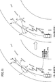
- FIG. 11 is a diagram for explaining the estimation of the road surface ⁇ of the traveling road surface based on the traveling state of the preceding vehicle.
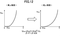
- FIG. 12 is a diagram showing a change in the allowable upper limit value of the relative speed when the road surface ⁇ of the road on which the surrounding vehicle is traveling is small
- FIG. 13 is a diagram showing a change in the speed limit distribution 40 in this case. is there.
- the road surface condition is obtained based on the information regarding the traveling state of the surrounding vehicle 3 traveling in front of the host vehicle 1 obtained through the inter-vehicle communication system 26 in step S10 of FIG.
- the road surface state is estimated by the estimation unit 10d.
- the estimated road surface state is one of the factors that affect the braking distance by the brake of the host vehicle 1, and in the present embodiment, the road surface ⁇ (the friction coefficient of the road surface) of the lane in which the host vehicle 1 is traveling is set. Presumed.
- the inter-vehicle communication system 26 repeatedly receives information related to the running state of the surrounding vehicle 3 at predetermined time intervals from the running or stopped vehicle around the host vehicle 1. Since this time interval is sufficiently short, for example, the road surface ⁇ of the road surface on which the host vehicle 1 will travel later is continuously estimated based on the traveling state of the preceding vehicle (the surrounding vehicle 3) traveling on the lane of the host vehicle 1. Thus, the road surface condition ahead can be grasped at an early stage.
- FIG. 11 is a diagram for explaining the estimation of the road surface ⁇ .
- the peripheral vehicle 3 traveling in front of the lane of the host vehicle uses information such as the travel position of the host vehicle, the vehicle attitude angle, the travel speed, and the rotation angle of the steering wheel as the inter-vehicle communication system. 26 is repeatedly transmitted.
- the transmitted information related to the traveling state of the surrounding vehicle 3 is received by the host vehicle 1 via the inter-vehicle communication system 26.
- the road surface state estimation unit 10d of the ECU 10 calculates a travel locus R of the peripheral vehicle 3 based on the travel position of the peripheral vehicle 3 received via the inter-vehicle communication system 26.
- the centrifugal force acting on the surrounding vehicle 3 is calculated.
- the centrifugal force since the balance with the lateral force generated between the tires and the road surface near the vehicle 3, it is possible to calculate the lateral force F l of the peripheral vehicle 3.
- the road surface state estimating unit 10d calculates the slip angle beta r of the rear wheels around the vehicle 3. That is, the slip angle ⁇ r of the rear wheel can be calculated as an angle formed between the tangent line R t of the travel locus R of the peripheral vehicle 3 and the central axis C in the front-rear direction of the peripheral vehicle 3. Furthermore, the steering angle of the front wheels of the peripheral vehicle 3 can be calculated based on the received rotation angle of the steering wheel of the peripheral vehicle 3, and the slip angle ⁇ f of the front wheel can be calculated based on this.
- a large lateral force F 1 is generated at a relatively small slip angle ⁇ r , ⁇ f on a road surface with a high road surface ⁇ .
- ⁇ r and ⁇ f are increased.
- information on the travel position, vehicle attitude angle, travel speed, and steering wheel rotation angle of the surrounding vehicle 3 is acquired via the inter-vehicle communication system 26, and the value of the road surface ⁇ is estimated. Yes.
- some or all of these pieces of information can be calculated based on information about the millimeter wave radar 22 and the camera 21 provided in the host vehicle 1 without using the inter-vehicle communication system 26.
- step S23 the value of the correction coefficient ⁇ in the above equation (2) for calculating the allowable upper limit value V lim of the relative speed is changed.
- the road surface state estimation unit 10d estimates the state of the traveling road surface of the surrounding vehicle 3 based on the operation information received by the inter-vehicle communication system 26.
- the road surface state estimation unit 10d estimates that the road surface state is longer than the normal time, and lowers the allowable relative speed upper limit value.
- step S24 the speed distribution setting unit 10e sets the speed limit distribution 40 based on the set correction coefficients ⁇ and ⁇ (the value of ⁇ remains the default), and once in the flowchart shown in FIG. The process in the ECU 10 returns to the flowchart shown in FIG.
- the speed limit distribution 40 set in step S24 changes from that shown on the left side of FIG. 13 to that shown on the right side as a result of the correction coefficient ⁇ being changed to a smaller value in step S23. That is, the speed limit distribution 40 is set so that the upper limit value of the relative speed to be allowed increases as the distance from the surrounding vehicle 3 increases.
- the road surface state estimation unit 10d estimates that the road surface state is a long braking distance, the upper limit value of the relative speed allowed for the distance from the surrounding vehicle 3 is decreased. Even when the road surface ⁇ is low, since the value of the correction coefficient ⁇ in the equation (1) is not changed, the width of the speed limit distribution 40 in the horizontal direction (the direction perpendicular to the traveling direction of the host vehicle) is the same as in normal times. It is.
- the speed limit is not set during normal time (high road surface ⁇ ) shown on the left side.
- the braking distance of the host vehicle 1 becomes long, and therefore, for the same distance Y 1 from the surrounding vehicle 3, The upper limit of the relative speed allowed is reduced.
- the upper limit value of the allowable relative speed is reduced.
- the relative speed is limited at an early stage while the vehicle 1 is sufficiently away from the surrounding vehicle 3, and the host vehicle 1 can be stopped safely enough even if the braking distance of the host vehicle 1 is increased. For this reason, even in a road surface state in which the braking distance of the host vehicle 1 is long, the anxiety given to the driver can be reduced.
- step S24 the speed limit setting 40 is set by the speed distribution setting unit 10e on the basis of the set correction coefficients ⁇ and ⁇ (both ⁇ and ⁇ are default), and once in the flowchart shown in FIG. The process in the ECU 10 returns to the flowchart shown in FIG.
- the speed limit in the travel direction in the speed limit distribution is reduced.
- a long inter-vehicle distance is set between the relative vehicle speed and the surrounding vehicle 3. For this reason, even when the braking distance of the host vehicle 1 is long, accidental approach between the host vehicle 1 and the surrounding vehicle 3 can be avoided, and the anxiety given to the driver can be reduced. Can do.
- the vehicle control apparatus 100 of the embodiment of the present invention when it is estimated that the road surface state is a long braking distance, the upper limit value of the relative speed to be allowed is reduced (FIG. 13).
- the allowable inter-vehicle distance with respect to the speed is lengthened, and anxiety given to the driver can be suppressed.
- the road surface state is a road surface state in which the information related to the traveling state of the surrounding vehicle 3 transmitted from the surrounding vehicle 3 is received and the braking distance is increased using this information. Therefore, the road surface condition can be estimated in detail, and the speed limit distribution 40 can be set appropriately.
- the road surface state is estimated using information about the traveling state transmitted from the surrounding vehicle 3, not only the state of the road surface on which the host vehicle 1 is currently traveling, but also the road surface ahead of which the host vehicle 1 travels later. Can be estimated, and even when the road surface condition ahead changes, it can be dealt with early.
- the road surface state estimation unit 10d estimates the road surface ⁇ of the traveling lane, and based on this, it is determined whether or not the road surface state increases the braking distance.
- the braking distance can be estimated by a simple method. Further, when it is estimated that the braking distance becomes long, the upper limit value of the allowable relative speed in the traveling direction is lowered (FIG. 13), so that sufficient safety can be ensured even when the braking distance is long.
- the vehicle control device 100 of the present embodiment when it is estimated that the road surface state is a long braking distance, the upper limit value of the relative speed allowed for the distance from the surrounding vehicle 3 is reduced. (FIG. 13) Therefore, for the same relative speed, the distance in the traveling direction between the surrounding vehicle 3 and the host vehicle 1 is increased, and the driver is provided with a sufficient sense of security even on a road surface where the braking distance is increased. Can do.
- the present invention has been described above, but various modifications can be made to the above-described embodiments.
- information is received from the surrounding vehicle 3 traveling ahead via the inter-vehicle communication system 26, and the road surface ⁇ is estimated based on this information. It has been determined whether or not the road surface condition affects the braking distance by the brake.
- the present invention can be configured to determine whether or not the road surface state affects the braking distance without estimating the road surface ⁇ .
- the road surface state estimation unit 10d estimates a road surface state that affects the braking distance based on the detection values of the wiper sensor and the outside air temperature sensor.
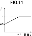
- the correction coefficient ⁇ when it is estimated that the road surface ⁇ of the traveling road surface of the surrounding vehicle 3 ahead is equal to or less than the predetermined amount, the correction coefficient ⁇ is decreased stepwise from 1 to 0.8.
- the correction coefficient ⁇ can be linearly reduced as shown in FIG.
- the correction coefficient ⁇ 1 in the normal state (high ⁇ road surface), and when the road surface ⁇ of the traveling road surface becomes smaller than the predetermined value ⁇ 1 (when it becomes smaller than the predetermined friction coefficient ⁇ 1 ).
- the correction coefficient ⁇ is linearly changed to a small value.
- the correction coefficient ⁇ is decreased, and the correction coefficient ⁇ is decreased to about 0.5 on an icing road surface where the road surface ⁇ is extremely small.
- Vehicle 10 Vehicle Control Operation Unit (ECU) DESCRIPTION OF SYMBOLS 10a Input processing part 10b Surrounding vehicle detection part 10c Target travel route calculation part 10d Road surface state estimation part 10e Speed distribution setting part 10f Control part 21 Camera 22 Millimeter wave radar 23 Vehicle speed sensor 24 Positioning system 25 Navigation system 26 Inter-vehicle communication system (vehicle) Information receiver) 31 Engine control system 32 Brake control system 33 Steering control system 40 Speed limit distribution 100 Vehicle control device
Abstract
様々な路面状態に対し、先行車両との間に適切な間隔を空け、運転者に与える不安感を抑制することができる車両制御装置を提供する。本発明は、車両の走行を制御する車両制御装置(100)であって、自車両(1)の周辺を走行している周辺車両(3)を検出する周辺車両検出部(10b)と、自車両のブレーキによる制動距離に影響を与える路面状態を推定する路面状態推定部(10d)と、周辺車両検出部によって検出された周辺車両の周囲に許容可能な相対速度の上限値を規定した制限速度分布(40)を設定する速度分布設定部(10e)と、この速度分布設定部によって設定された制限速度分布を満足するように自車両の速度及び/又は操舵を制御する制御部(10f)と、を有し、速度分布設定部は、路面状態推定部により制動距離が長くなる路面状態であると推定された場合には、許容する相対速度の上限値を低下させることを特徴としている。
Description
本発明は車両制御装置に関し、特に、車両の走行を制御する車両制御装置に関する。
特開2006-218935号公報(特許文献1)には、車両用走行支援装置が記載されている。この車両用走行支援装置においては、自車両の進行方向にある物体を検出し、この物体と自車両の最接近時において安全距離が確保されているか否かを予測し、安全距離が確保できないと予測されたときには、走行支援制御が実行される。また、この車両用走行支援装置においては、物体の向きが検出され、この向きに応じて安全距離が設定される。
しかしながら、特許文献1記載の車両用走行支援装置による制御は、単に衝突の回避を目的としたものであり、自車両の通常の走行時において、先行車両(駐車車両)を追い抜いたり、追い越したりする場合には、衝突が回避されるだけでは不十分である。即ち、先行車両を追い抜き、追い越す場合には、運転者に不安感を与えることのない十分な間隔を先行車両(駐車車両)との間に維持する必要がある。
この目的を達成するために、出願人は、先行車両等の対象物の周囲に、複数の相対速度の許容上限値を規定した制限速度分布を設定し、その許容上限値を超えないように自車両の車速や、操舵を制御する車両制御装置を開発した(国際特許出願JP2016/075233号)。このような車両制御装置を搭載することにより、先行車両等の対象物を追い抜き、追い越す際にも、対象物との間に十分な間隔を維持することができ、運転者に不安を与えにくい車両制御に成功している。
しかしながら、運転者が、安全、安心と感じる先行車両との間の距離は常に一定ではなく、自車両が走行している路面の状態によって変化する。従って、車両制御装置によって、先行車両との間に或る一定の間隔をとるように自車両が制御されている場合には、走行する路面の状態によっては運転者がその間隔を不安に感じることもある。しかしながら、如何なる路面の状態においても運転者が不安を感じることがない間隔をとるように自車両が制御されていると、運転者はその間隔を長すぎると感じ、苛立ちを覚える場合がある。
従って、本発明は、様々な路面状態に対し、先行車両との間に適切な間隔を空け、運転者に与える不安感を抑制することができる車両制御装置を提供することを目的としている。
従って、本発明は、様々な路面状態に対し、先行車両との間に適切な間隔を空け、運転者に与える不安感を抑制することができる車両制御装置を提供することを目的としている。
上述した課題を解決するために、本発明は、車両の走行を制御する車両制御装置であって、自車両の周辺を走行している周辺車両を検出する周辺車両検出部と、自車両のブレーキによる制動距離に影響を与える路面状態を推定する路面状態推定部と、周辺車両検出部によって検出された周辺車両の周囲に許容可能な相対速度の上限値を規定した制限速度分布を設定する速度分布設定部と、この速度分布設定部によって設定された制限速度分布を満足するように自車両の速度及び/又は操舵を制御する制御部と、を有し、速度分布設定部は、路面状態推定部により制動距離が長くなる路面状態であると推定された場合には、許容する相対速度の上限値を低下させることを特徴としている。
このように構成された本発明においては、周辺車両検出部が自車両の周辺を走行している周辺車両を検出し、路面状態推定部は、自車両のブレーキによる制動距離に影響を与える路面状態を推定する。速度分布設定部は、周辺車両検出部によって検出された周辺車両の周囲に許容可能な相対速度の上限値を規定した制限速度分布を設定する。また、速度分布設定部は、路面状態推定部により制動距離が長くなる路面状態であると推定された場合には、許容する相対速度の上限値を低下させ、制御部は、この制限速度分布を満足するように自車両の速度及び/又は操舵を制御する。
このように構成された本発明によれば、制動距離が長くなる路面状態であると推定された場合には、許容する相対速度の上限値を低下させるので、同一の相対速度に対して許容される車間距離が長くされ、運転者に与える不安感を抑制することができる。
本発明において、好ましくは、路面状態推定部は、周辺車両検出部によって検出された周辺車両から発信された周辺車両の走行状態に関する情報を受信し、この情報を使用して、制動距離が長くなる路面状態であるか否かを推定する。
車両が走行している路面の状態は必ずしも一様ではなく、自車両の走行と共に走行路面の路面μの値が変化し、制動距離も変化する場合がある。このため、例えば、天候や気温を考慮しただけでは十分な制動距離の推定は困難であり、路面の状態をより正確に把握する必要がある。一例として、特許第5035419号には路面摩擦係数推定方法が記載されており、この推定方法においては、タイヤが発生する横力、スリップ角、ある路面μにおけるタイヤの特性曲線等に基づいて、走行路面の路面μを推定している。このように、車両の走行状態に基づいて走行中の路面の路面μを推定する技術が知られている。上記のように構成された本発明によれば、周辺車両から発信された周辺車両の走行状態に関する情報を受信し、この情報を使用して制動距離が長くなる路面状態であるか否かを推定するので、路面の状態をきめ細かく推定することができ、制限速度分布を適切に設定することができる。また、周辺車両から発信された走行状態に関する情報を使用して路面状態を推定するので、自車両が現在走行している路面の状態ばかりでなく、自車両が後に走行する前方の路面の状態を推定することができ、前方の路面状態が変化している場合でも早期に対応することができる。
本発明において、好ましくは、路面状態推定部は走行車線の路面μを推定し、この路面μが所定値以下である場合に、制動距離が長くなる路面状態であると推定するように構成され、速度分布設定部は、制動距離が長くなる路面状態であると推定された場合には、自車両の走行方向における許容相対速度の上限値を低下させる。
このように構成された本発明によれば、路面状態推定部が走行車線の路面μを推定し、これに基づいて制動距離が長くなる路面状態であるか否かが判断されるので、簡便な手法で制動距離を推定することができる。また、制動距離が長くなると推定された場合には、走行方向における許容相対速度の上限値を低下させるので、制動距離が長い状態でも十分な安全性を確保することができる。
本発明において、好ましくは、速度分布設定部は、周辺車両からの距離が離れるほど、許容する相対速度の上限値が高くなるように制限速度分布を設定し、路面状態推定部により制動距離が長くなる路面状態であると推定された場合には、周辺車両からの距離に対して許容する相対速度の上限値を低下させる。
このように構成された本発明によれば、制動距離が長くなる路面状態であると推定された場合に、周辺車両からの距離に対して許容する相対速度の上限値が低下されるので、同一の相対速度に対して、周辺車両と自車両の間の走行方向の間隔が大きくされ、制動距離が長くなる路面状態でも運転者に十分な安心感を与えることができる。
本発明の車両制御装置によれば、自車両が走行する様々な路面状態に対し、先行車両との間に適切な間隔を空け、運転者に与える不安感を抑制することができる。
以下、添付図面を参照して、本発明の実施形態による車両制御装置について説明する。まず、図1及び図2を参照して、車両制御装置の構成について説明する。図1は車両制御装置の構成図であり、図2は車両制御装置の制御ブロック図である。
本実施形態の車両制御装置100は、これを搭載した車両1(図3等参照)に対して複数の運転支援モードにより、それぞれ異なる運転支援制御を提供するように構成されている。運転者は、複数の運転支援モードから所望の運転支援モードを選択可能である。
図1に示すように、車両制御装置100は車両1に搭載された、車両制御演算部(ECU)10と、複数のセンサ及びスイッチと、複数の制御システムと、運転支援モードについてのユーザ入力を行うための運転者操作部(図示せず)を備えている。複数のセンサ及びスイッチには、車室外を撮像するカメラ21、ミリ波レーダ22,車両の挙動を検出する車速センサ23,測位システム24,ナビゲーションシステム25、及び車車間通信システム26が含まれる。また、複数の制御システムには、エンジン制御システム31,ブレーキ制御システム32,ステアリング制御システム33が含まれる。
図1に示すECU10は、CPU,各種プログラムを記憶するメモリ,入出力装置等を備えたコンピュータにより構成される。ECU10は、運転者操作部(図示せず)から受け取った運転支援モード選択信号や設定車速信号、及び、複数のセンサ及びスイッチから受け取った信号に基づき、エンジン制御システム31,ブレーキ制御システム32,ステアリング制御システム33に対して、それぞれエンジンシステム,ブレーキシステム,ステアリングシステムを適宜に作動させるための要求信号を出力可能に構成されている。
カメラ21は、車両1の前方を撮像し、撮像した画像データを出力する。ECU10は、画像データに基づいて対象物(例えば、車両、歩行者、道路、区画線(車線境界線、白線、黄線)、交通信号、交通標識、停止線、交差点、先行車両、障害物等)を特定する。また、車両1の側方や後方を撮像する車室外カメラを設けることもできる。さらに、運転中の運転者を撮像する車室内カメラを車両に備えることもできる。
ミリ波レーダ22は、対象物(特に、先行車、駐車車両、歩行者、障害物等)の位置及び速度を測定する測定装置であり、車両1の前方へ向けて電波(送信波)を送信し、対象物により送信波が反射されて生じた反射波を受信する。そして、ミリ波レーダ22は、送信波と受信波に基づいて、車両1と対象物との間の距離(例えば、車間距離)や車両1に対する対象物の相対速度を測定する。なお、本実施形態においては、ミリ波レーダ22として、車両1の前方の対象物を検出する前方レーダ、側方の対象物の対象物を検出する側方レーダ、及び車両1の後方の対象物を検出する後方レーダが備えられている。また、ミリ波レーダ22に代えて、レーザレーダや超音波センサ等を用いて対象物との距離や相対速度を測定するように構成してもよい。また、複数のセンサを用いて、位置及び速度測定装置を構成してもよい。
車速センサ23は、車両1の絶対速度を検出するように構成されている。
車速センサ23は、車両1の絶対速度を検出するように構成されている。
測位システム24は、GPSシステム及び/又はジャイロシステムであり、車両1の位置(現在車両位置情報)を検出する。
ナビゲーションシステム25は、内部に地図情報を格納しており、ECU10へ地図情報を提供することができる。ECU10は、地図情報及び現在車両位置情報に基づいて、車両1の周囲(特に、進行方向前方)に存在する道路、交差点、交通信号、建造物等を特定する。地図情報は、ECU10内に格納されていてもよい。
ナビゲーションシステム25は、内部に地図情報を格納しており、ECU10へ地図情報を提供することができる。ECU10は、地図情報及び現在車両位置情報に基づいて、車両1の周囲(特に、進行方向前方)に存在する道路、交差点、交通信号、建造物等を特定する。地図情報は、ECU10内に格納されていてもよい。
車車間通信システム26は、車両と車両の間の通信システムであり、自車両と周辺を走行している車両との間で、車両の位置情報や、走行速度の情報、運転者による加減速や操舵等に関する操作情報等を交換するように構成されている。この車車間通信システム26により、自車両の走行経路上の比較的遠方に停車している、又は走行している車両の位置、速度、ステアリングホイールの回転角等の運転者による操作、車両姿勢角等の情報を取得することができる。
エンジン制御システム31は、車両1のエンジンを制御するコントローラである。ECU10は、車両1を加速又は減速させる必要がある場合に、エンジン制御システム31に対して、目標加減速度が得られるようにエンジン出力の変更を要求するエンジン出力変更要求信号を出力する。
ブレーキ制御システム32は、車両1のブレーキ装置を制御するためのコントローラである。ECU10は、車両1を減速させる必要がある場合に、ブレーキ制御システム32に対して、目標加減速度が得られるように車両1への制動力の発生を要求するブレーキ要求信号を出力する。
ステアリング制御システム33は、車両1のステアリング装置を制御するコントローラである。ECU10は、車両1の進行方向を変更する必要がある場合に、ステアリング制御システム33に対して、目標蛇角が得られるように操舵方向の変更を要求する操舵方向変更要求信号を出力する。
図2に示すように、ECU10は、入力処理部10a、周辺車両検出部10b、目標走行経路算出部10c、路面状態推定部10d、速度分布設定部10e、及び制御部10fとして機能する単一のCPUを備えている。なお、本実施形態では、単一のCPUが複数の上記機能を実行するように構成されているが、これに限らず、複数のCPUがこれら機能を実行するように構成することができる。
入力処理部10aは、各センサ、ナビゲーションシステム25、及び車車間通信システム26から入力された入力情報を処理するように構成されている。この入力処理部10aは、走行路面を撮像したカメラ21の画像を解析し、自車両が走行している走行車線(車線の両側の区画線)を検出する画像解析部として機能する。
周辺車両検出部10bは、ミリ波レーダ22、カメラ21、車車間通信システム26等からの入力情報に基づいて自車両の周辺を走行している周辺車両等を検出するように構成されている。
周辺車両検出部10bは、ミリ波レーダ22、カメラ21、車車間通信システム26等からの入力情報に基づいて自車両の周辺を走行している周辺車両等を検出するように構成されている。
目標走行経路算出部10cは、ミリ波レーダ22、カメラ21、各センサ等からの入力情報に基づいて車両の目標走行経路を算出するように構成されている。
路面状態推定部10dは、ミリ波レーダ22、カメラ21、ナビゲーションシステム25、車車間通信システム26等からの入力情報に基づいて、自車両1のブレーキによる制動距離に影響を与える路面状態を推定するように構成されている。路面状態推定部10dによる路面状態の推定については後述する。
路面状態推定部10dは、ミリ波レーダ22、カメラ21、ナビゲーションシステム25、車車間通信システム26等からの入力情報に基づいて、自車両1のブレーキによる制動距離に影響を与える路面状態を推定するように構成されている。路面状態推定部10dによる路面状態の推定については後述する。
速度分布設定部10eは、周辺車両の周囲に許容可能な相対速度の上限値を規定した制限速度分布を設定する。例えば、速度分布設定部10eは、周辺車両検出部10bによって周辺に回避すべき車両が検出された場合に、周辺車両に対して自車両1が走行可能な許容相対速度の上限ラインの分布(制限速度分布)を設定する。なお、周辺車両検出部10bによって車両以外の回避すべき物標が検出された場合にも、速度分布設定部10eは、その周囲に制限速度分布を設定する。
さらに、制御部10fは、車両が走行可能な許容相対速度の上限ラインである制限速度分布を満足するように自車両の速度及び操舵を制御する。具体的には、制御部10fは、目標走行経路算出部10cによって算出された目標走行経路を、制限速度分布を満足するように補正して補正走行経路を算出する。次いで、制限速度分布を満足する補正走行経路の中から、所定の制約条件を満たす走行経路を選択する。さらに、制御部10fは、選択された走行経路の中から所定の評価関数が最小となる走行経路を最適な補正走行経路として決定するように構成されている。即ち、制御部10fは、制限速度分布、所定の評価関数及び所定の制約条件に基づいて補正走行経路を算出する。また、本実施形態においては、最適な補正走行経路を決定するための制約条件は、選択されている運転支援モードや、運転者による運転状況に基づいて、適宜設定される。なお、制約条件や評価関数を使用することなく、制御部10fが制限速度分布を満足する走行経路を生成するように本発明を構成することもできる。
さらに、制御部10fは、決定された最適な補正走行経路を走行すべく、少なくともエンジン制御システム31,ブレーキ制御システム32,又はステアリング制御システム33のいずれか1つ又は複数に対する要求信号を生成し、出力する。
次に、本実施形態による車両制御装置100が備える運転支援モードについて説明する。本実施形態では、運転支援モードとして、4つのモードが備えられている。即ち、運転者操舵モードである速度制限モードと、自動操舵モードである先行車追従モードと、運転者操舵モードである自動速度制御モードと、何れの運転支援モードも選択されていない場合に実行される基本制御モードが備えられている。
<先行車追従モード>
先行車追従モードは、基本的に、車両1と先行車との間に車速に応じた所定の車間距離を維持しつつ、車両1を先行車に追従走行させる自動操舵モードであり、車両制御装置100による自動的なステアリング制御,速度制御(エンジン制御,ブレーキ制御),障害物回避制御(速度制御及びステアリング制御)を伴う。
先行車追従モードは、基本的に、車両1と先行車との間に車速に応じた所定の車間距離を維持しつつ、車両1を先行車に追従走行させる自動操舵モードであり、車両制御装置100による自動的なステアリング制御,速度制御(エンジン制御,ブレーキ制御),障害物回避制御(速度制御及びステアリング制御)を伴う。
先行車追従モードでは、車線両端部の検出の可否、及び、先行車の有無に応じて、異なるステアリング制御及び速度制御が行われる。ここで、車線両端部とは、車両1が走行する車線の両端部(白線等の区画線,道路端,縁石,中央分離帯,ガードレール等)であり、隣接する車線や歩道等との境界である。ECU10に備えられた入力処理部10aは、この車線両端部をカメラ21により撮像された画像データから検出する。また、ナビゲーションシステム25の地図情報から車線両端部を検出してもよい。しかしながら、例えば、車両1が整備された道路ではなく、車線が存在しない平原を走行する場合や、カメラ21からの画像データの読取り不良等の場合に車線両端部が検出できない場合が生じ得る。
また、本実施形態では、先行車検出部としてのECU10は、カメラ21による画像データ、及びミリ波レーダ22のうちの前方レーダによる測定データにより、先行車を検出する。具体的には、カメラ21による画像データにより前方を走行する他車両を周辺車両として検出する。更に、本実施形態では、ミリ波レーダ22による測定データにより、車両1と周辺車両との車間距離が所定距離(例えば、400~500m)以下である場合に、当該他車両が先行車として検出される。
なお、先行車追従モードにおいて、先行車(周辺車両)の有無、車線両端部の検出の可否にかかわらず、入力処理部10aによって回避すべき周辺物標が検出された場合には、目標走行経路が補正され、自動的に障害物(周辺物標)が回避される。
<自動速度制御モード>
また、自動速度制御モードは、運転者によって予め設定された所定の設定車速(一定速度)を維持するように速度制御する運転者操舵モードであり、車両制御装置100による自動的な速度制御(エンジン制御,ブレーキ制御)を伴うが、ステアリング制御は行われない。この自動速度制御モードでは、車両1は、設定車速を維持するように走行するが、運転者によるアクセルペダルの踏み込みにより設定車速を超えて増速され得る。また、運転者がブレーキ操作を行った場合には、運転者の意思が優先され、設定車速から減速される。また、先行車に追いついた場合には、車速に応じた車間距離を維持しながら先行車に追従するように速度制御され、先行車が存在しなくなると、再び設定車速に復帰するように速度制御される。
また、自動速度制御モードは、運転者によって予め設定された所定の設定車速(一定速度)を維持するように速度制御する運転者操舵モードであり、車両制御装置100による自動的な速度制御(エンジン制御,ブレーキ制御)を伴うが、ステアリング制御は行われない。この自動速度制御モードでは、車両1は、設定車速を維持するように走行するが、運転者によるアクセルペダルの踏み込みにより設定車速を超えて増速され得る。また、運転者がブレーキ操作を行った場合には、運転者の意思が優先され、設定車速から減速される。また、先行車に追いついた場合には、車速に応じた車間距離を維持しながら先行車に追従するように速度制御され、先行車が存在しなくなると、再び設定車速に復帰するように速度制御される。
<速度制限モード>
また、速度制限モードは、車両1の車速が速度標識による制限速度又は運転者によって設定された設定速度を超えないように、速度制御する運転者操舵モードであり、車両制御装置100による自動的な速度制御(エンジン制御)を伴う。制限速度は、カメラ21により撮像された速度標識や路面上の速度表示の画像データをECU10が画像認識処理することにより特定してもよいし、外部からの無線通信により受信してもよい。速度制限モードでは、運転者が制限速度を超えるようにアクセルペダルを踏み込んだ場合であっても、車両1は制限速度までしか増速されない。
また、速度制限モードは、車両1の車速が速度標識による制限速度又は運転者によって設定された設定速度を超えないように、速度制御する運転者操舵モードであり、車両制御装置100による自動的な速度制御(エンジン制御)を伴う。制限速度は、カメラ21により撮像された速度標識や路面上の速度表示の画像データをECU10が画像認識処理することにより特定してもよいし、外部からの無線通信により受信してもよい。速度制限モードでは、運転者が制限速度を超えるようにアクセルペダルを踏み込んだ場合であっても、車両1は制限速度までしか増速されない。
<基本制御モード>
また、基本制御モードは、何れの運転支援モードも選択されていないときのモード(オフモード)であり、車両制御装置100による自動的なステアリング制御及び速度制御は行われない。ただし、車両1が対向車等の周辺車両に衝突する可能性がある場合には、衝突を回避する制御が実行される。また、これらの衝突回避は、先行車追従モード,自動速度制御,速度制限モードにおいても同様に実行される。
また、基本制御モードは、何れの運転支援モードも選択されていないときのモード(オフモード)であり、車両制御装置100による自動的なステアリング制御及び速度制御は行われない。ただし、車両1が対向車等の周辺車両に衝突する可能性がある場合には、衝突を回避する制御が実行される。また、これらの衝突回避は、先行車追従モード,自動速度制御,速度制限モードにおいても同様に実行される。
次に、図3乃至図5を参照して、本実施形態による車両制御装置100により計算される複数の走行経路について説明する。図3乃至図5は、それぞれ第1走行経路~第3走行経路の説明図である。本実施形態では、ECU10に備えられた目標走行経路算出部10cが、以下の第1走行経路R1~第3走行経路R3を時間的に繰返し計算するように構成されている(例えば、0.1秒毎)。本実施形態では、ECU10は、センサ等の情報に基づいて、現時点から所定期間(例えば、3秒)が経過するまでの間の走行経路を計算する。走行経路Rx(x=1,2,3)は、走行経路上の車両1の目標位置(Px_k)及び目標速度(Vx_k)により特定される(k=0,1,2,・・・,n)。更に、各目標位置において、目標速度以外に複数の変数(加速度、加速度変化量、ヨーレート、操舵角、車両角度等)について目標値が特定される。
なお、図3乃至図5における走行経路(第1走行経路~第3走行経路)は、車両1が走行する走行路上又は走行路周辺の物標(周辺車両、歩行者等の障害物)に関する周辺物標の検出情報を考慮せずに、走行路の形状,先行車の走行軌跡,車両1の走行挙動,及び設定車速に基づいて計算される。このように、本実施形態では、周辺物標の情報が計算に考慮されないので、これら複数の走行経路の全体的な計算負荷を低く抑えることができる。
以下では、理解の容易のため、車両1が直線区間5a,カーブ区間5b,直線区間5cからなる道路5を走行する場合において計算される各走行経路について説明する。道路5は、左右の車線5L,5Rからなる。現時点において、車両1は、直線区間5aの車線5L上を走行しているものとする。
(第1走行経路)
図3に示すように、第1走行経路R1は、道路5の形状に即して車両1に走行路である車線5L内の走行を維持させるように所定期間分だけ設定される。詳しくは、第1走行経路R1は、直線区間5a,5cでは車両1が車線5Lの中央付近の走行を維持するように設定され、カーブ区間5bでは車両1が車線5Lの幅方向中央よりも内側又はイン側(カーブ区間の曲率半径Lの中心O側)を走行するように設定される。
図3に示すように、第1走行経路R1は、道路5の形状に即して車両1に走行路である車線5L内の走行を維持させるように所定期間分だけ設定される。詳しくは、第1走行経路R1は、直線区間5a,5cでは車両1が車線5Lの中央付近の走行を維持するように設定され、カーブ区間5bでは車両1が車線5Lの幅方向中央よりも内側又はイン側(カーブ区間の曲率半径Lの中心O側)を走行するように設定される。
目標走行経路算出部10cは、カメラ21により撮像された車両1の周囲の画像データの画像認識処理を実行し、車線両端部6L,6Rを検出する。車線両端部は、上述のように、区画線(白線等)や路肩等である。更に、目標走行経路算出部10cは、検出した車線両端部6L,6Rに基づいて、車線5Lの車線幅W及びカーブ区間5bの曲率半径Lを算出する。また、ナビゲーションシステム25の地図情報から車線幅W及び曲率半径Lを取得してもよい。更に、目標走行経路算出部10cは、画像データから速度標識Sや路面上に表示された制限速度を読み取る。なお、上述のように、制限速度を外部からの無線通信により取得してもよい。
目標走行経路算出部10cは、直線区間5a,5cでは、車線両端部6L,6Rの幅方向の中央部を車両1の幅方向中央部(例えば、重心位置)が通過するように、第1走行経路R1の複数の目標位置P1_kを設定する。
一方、目標走行経路算出部10cは、カーブ区間5bでは、カーブ区間5bの長手方向の中央位置P1_cにおいて、車線5Lの幅方向中央位置からイン側への変位量Wsを最大に設定する。この変位量Wsは、曲率半径L,車線幅W,車両1の幅寸法D(ECU10のメモリに格納された規定値)に基づいて計算される。そして、目標走行経路算出部10cは、カーブ区間5bの中央位置P1_cと直線区間5a,5cの幅方向中央位置とを滑らかにつなぐように第1走行経路R1の複数の目標位置P1_kを設定する。なお、カーブ区間5bへの進入前後においても、直線区間5a,5cのイン側に第1走行経路R1を設定してもよい。
第1走行経路R1の各目標位置P1_kにおける目標速度V1_kは、原則的に、運転者が設定した速度、又は車両制御装置100によって予め設定された所定の設定車速(一定速度)に設定される。しかしながら、この設定車速が、速度標識S等から取得された制限速度、又は、カーブ区間5bの曲率半径Lに応じて規定される制限速度を超える場合、走行経路上の各目標位置P1_kの目標速度V1_kは、2つの制限速度のうち、より低速な制限速度に制限される。さらに、目標走行経路算出部10cは、車両1の現在の挙動状態(即ち、車速,加速度,ヨーレート,操舵角,横加速度等)に応じて、目標位置P1_k,目標車速V1_kを適宜に補正する。例えば、現車速が設定車速から大きく異なっている場合は、車速を設定車速に近づけるように目標車速が補正される。
(第2走行経路)
また、図4に示すように、第2走行経路R2は、先行車3(周辺車両)の走行軌跡を追従するように所定期間分だけ設定される。目標走行経路算出部10cは、カメラ21による画像データ,ミリ波レーダ22による測定データ,車速センサ23による車両1の車速に基づいて、車両1の走行する車線5L上の先行車3の位置及び速度を継続的に計算して、これらを先行車軌跡情報として記憶し、この先行車軌跡情報に基づいて、先行車3の走行軌跡を第2走行経路R2(目標位置P2_k、目標速度V2_k)として設定する。
また、図4に示すように、第2走行経路R2は、先行車3(周辺車両)の走行軌跡を追従するように所定期間分だけ設定される。目標走行経路算出部10cは、カメラ21による画像データ,ミリ波レーダ22による測定データ,車速センサ23による車両1の車速に基づいて、車両1の走行する車線5L上の先行車3の位置及び速度を継続的に計算して、これらを先行車軌跡情報として記憶し、この先行車軌跡情報に基づいて、先行車3の走行軌跡を第2走行経路R2(目標位置P2_k、目標速度V2_k)として設定する。
(第3走行経路)
また、図5に示すように、第3走行経路R3は、運転者による車両1の現在の運転状態に基づいて所定期間分だけ設定される。即ち、第3走行経路R3は、車両1の現在の走行挙動から推定される位置及び速度に基づいて設定される。
目標走行経路算出部10cは、車両1の操舵角,ヨーレート,横加速度に基づいて、所定期間分の第3走行経路R3の目標位置P3_kを計算する。ただし、目標走行経路算出部10cは、車線両端部が検出される場合、計算された第3走行経路R3が車線端部に近接又は交差しないように、目標位置P3_kを補正する。
また、図5に示すように、第3走行経路R3は、運転者による車両1の現在の運転状態に基づいて所定期間分だけ設定される。即ち、第3走行経路R3は、車両1の現在の走行挙動から推定される位置及び速度に基づいて設定される。
目標走行経路算出部10cは、車両1の操舵角,ヨーレート,横加速度に基づいて、所定期間分の第3走行経路R3の目標位置P3_kを計算する。ただし、目標走行経路算出部10cは、車線両端部が検出される場合、計算された第3走行経路R3が車線端部に近接又は交差しないように、目標位置P3_kを補正する。
また、目標走行経路算出部10cは、車両1の現在の車速,加速度に基づいて、所定期間分の第3走行経路R3の目標速度V3_kを計算する。なお、目標速度V3_kが速度標識S等から取得された制限速度を超えてしまう場合は、制限速度を超えないように目標速度V3_kを補正してもよい。
次に、本実施形態による車両制御装置100における運転支援モードと走行経路との関係について説明する。本実施形態では、運転者が1つの運転支援モードを選択すると、選択された運転支援モードに応じて走行経路が選択されるように構成されている。
先行車追従モードの選択時には、車線両端部が検出されていると、先行車の有無にかかわらず、第1走行経路が適用される。この場合、設定された設定車速が目標速度となる。
一方、先行車追従モードの選択時において、車線両端部が検出されず、先行車が検出された場合、第2走行経路が適用される。この場合、目標速度は、先行車の車速に応じて設定される。また、先行車追従モードの選択時において、車線両端部が検出されず、先行車も検出されない場合、第3走行経路が適用される。
一方、先行車追従モードの選択時において、車線両端部が検出されず、先行車が検出された場合、第2走行経路が適用される。この場合、目標速度は、先行車の車速に応じて設定される。また、先行車追従モードの選択時において、車線両端部が検出されず、先行車も検出されない場合、第3走行経路が適用される。
また、自動速度制御モードの選択時には、第3走行経路が適用される。自動速度制御モードは、上述のように速度制御を自動的に実行するモードであり、設定された設定車速が目標速度となる。また、運転者によるステアリングホイールの操作に基づいてステアリング制御が実行される。
また、速度制限モードの選択時にも第3走行経路が適用される。速度制限モードも、上述のように速度制御を自動的に実行するモードであり、目標速度は、制限速度以下の範囲で、運転者によるアクセルペダルの踏み込み量に応じて設定される。また、運転者によるステアリングホイールの操作に基づいてステアリング制御が実行される。
また、基本制御モード(オフモード)の選択時には、第3走行経路が適用される。基本制御モードは、基本的に、速度制限モードにおいて制限速度が設定されない状態と同様である。
次に、図6乃至図8を参照して、本実施形態によるECU10の制御部10fにおいて実行される走行経路補正処理について説明する。図6は走行経路の補正による障害物回避の説明図である。図7は周辺車両を回避する際の周辺車両と自車両との間の距離と、相対速度の許容上限値の関係を示す説明図であり、図8は車両モデルの説明図である。
図6では、車両1は走行路(車線)7上を走行しており、走行中又は停車中の車両3(周辺車両)とすれ違って、車両3を追い抜こうとしている。
図6では、車両1は走行路(車線)7上を走行しており、走行中又は停車中の車両3(周辺車両)とすれ違って、車両3を追い抜こうとしている。
一般に、道路上又は道路付近の障害物(例えば、先行車、駐車車両、歩行者等)とすれ違うとき(又は追い抜くとき)、車両1の運転者は、進行方向に対して直交する横方向において、車両1と障害物との間に所定のクリアランス又は間隔(横方向距離)を保ち、且つ、車両1の運転者が安全と感じる速度に減速する。具体的には、先行車が急に進路変更したり、障害物の死角から歩行者が出てきたり、駐車車両のドアが開いたりするといった危険を回避するため、クリアランスが小さいほど、障害物に対する相対速度は小さくされる。
また、一般に、後方から先行車に近づいているとき、車両1の運転者は、進行方向に沿った車間距離(縦方向距離)に応じて速度(相対速度)を調整する。具体的には、車間距離が大きいときは、接近速度(相対速度)が大きく維持されるが、車間距離が小さくなると、接近速度は低速にされる。そして、所定の車間距離で両車両の間の相対速度はゼロとなる。これは、先行車が駐車車両であっても同様である。
このように、運転者は、障害物と車両1との間の距離(横方向距離及び縦方向距離を含む)と相対速度との関係を考慮しながら、危険がないように車両1を運転している。
そこで、本実施形態では、図6に示すように、車両1は、車両1から検知される障害物(例えば、駐車車両3)に対して、障害物の周囲に(横方向領域、後方領域、及び前方領域にわたって)又は少なくとも障害物と車両1との間に、車両1の進行方向における相対速度についての許容上限値を規定する2次元分布(制限速度分布40)を設定するように構成されている。制限速度分布40では、障害物の周囲の各点において、相対速度の許容上限値Vlimが設定されている。このように、速度分布設定部10eは、周辺車両3からの距離に応じて複数の制限速度分布40を設定する。本実施形態では、すべての運転支援モードにおいて、障害物に対する車両1の相対速度が制限速度分布40内の許容上限値Vlimを超えることがないように走行経路の補正が実施される。また、後述するように、障害物の周囲に設定される制限速度分布40は、障害物が周辺車両である場合には、その周辺車両から車車間通信システム26を介して受信した情報等に応じて異なるものが設定される。
図6から分かるように、制限速度分布40は、原則的に、障害物からの横方向距離及び縦方向距離が小さくなるほど(障害物に近づくほど)、相対速度の許容上限値が小さくなるように設定される。即ち、制限速度分布40は、同じ許容上限値を有する点を連結した複数の等相対速度線として設定される。等相対速度線a,b,c,dは、それぞれ許容上限値Vlimが0km/h,20km/h,40km/h,60km/hの制限速度分布40を示している。本例では、各制限速度分布40は、略矩形に設定されている。このように、速度分布設定部10eは、入力処理部10aによって回避すべき障害物(周辺物標)が認識された場合には、障害物に対して車両が走行可能な許容相対速度の上限ラインである制限速度分布40を設定する。そして、制御部10fは、この制限速度分布40を満足するように、目標走行経路算出部10cによって算出された目標走行経路を補正する。
なお、制限速度分布40は、必ずしも障害物の周囲全体にわたって設定されなくてもよく、少なくとも障害物の後方、及び、車両1が存在する障害物の横方向の一方側(図6では、車両3の右側領域)に設定されればよい。また、制限速度分布40は、左右非対称に設定されても良い。
図7に示すように、車両1が障害物に対して或る相対速度で走行する場合(図6の例では障害物である車両3は停車しているので、相対速度は車両1の絶対速度に等しい)において、許容上限値Vlimは、障害物からの距離に対して2次関数的に増加するように設定される。即ち、相対速度の許容上限値Vlim[km/h]は、障害物からの横方向のクリアランスXに対し、
Vlim=αk1(X-DX0)2、 (X≧DX0) (1)
Vlim=0 (X<DX0)
により設定される。
Vlim=αk1(X-DX0)2、 (X≧DX0) (1)
Vlim=0 (X<DX0)
により設定される。
上記式(1)において、k1は、横方向のクリアランスXに対するVlimの変化度合いに関連するゲイン係数であり、障害物の種類等に依存して設定される。また、安全距離DX0も障害物の種類等に依存して設定することができる。一例として、本実施形態においては安全距離DX0=0.2[m]に設定されている。さらに、補正係数αは、障害物が周辺車両である場合において、その周辺車両から車車間通信システム26を介して受信された、周辺車両の運転者による操作情報等に応じて変更される係数である。補正係数αの設定については後述する。
また、式(1)に示すように、許容上限値Vlimは、障害物の横方向においては、クリアランスXがDX0(安全距離)までは0(ゼロ)km/hであり、DX0以上で2次関数的に増加する。即ち、安全確保のため、クリアランスXがDX0以下では車両1は許容される相対速度がゼロとなる。一方、クリアランスXがDX0以上では、クリアランスが大きくなるほど、車両1は大きな相対速度ですれ違うことが許容される。
一方、障害物の縦方向(車両1の進行方向)においては、相対速度の許容上限値Vlim[km/h]は、障害物までの進行方向の距離Yに対し、
Vlim=βk2(Y-DY0)2/Vs、 (Y≧DY0) (2)
Vlim=0 (Y<DY0)
により設定される。
Vlim=βk2(Y-DY0)2/Vs、 (Y≧DY0) (2)
Vlim=0 (Y<DY0)
により設定される。
上記式(2)において、Vs[km/h]は自車両1の走行速度であり、また、k2は進行方向の距離Y(障害物までの距離)に対するVlimの変化度合いに関連するゲイン係数であり、障害物の種類等に依存して設定される。また、安全距離DY0も障害物の種類等に依存して設定することができる。一例として、本実施形態においては安全距離DY0=2[m]に設定されている。さらに、補正係数α、βは、障害物が周辺車両である場合において、その周辺車両から車車間通信システム26等を介して受信された、周辺車両の運転者による操作情報等に応じて変更される係数である。補正係数α、βの設定については後述する。
式(2)に表されているように、許容上限値Vlimは、自車両の進行方向(縦方向)においては、縦方向の距離YがDY0(安全距離)までは0(ゼロ)km/hであり、DY0以上で2次関数的に増加する。即ち、安全確保のため、障害物までの距離YがDY0以下では車両1に許容される相対速度がゼロとなる。一方、距離YがDY0以上では、距離Yが大きくなるほど、車両1は大きな相対速度で接近することが許容される。また、縦方向においては、許容上限値Vlimは、自車両1の走行速度Vsに反比例するように設定される。即ち、自車両1の走行速度Vsが高いほど自車両1の制動距離が長くなるので、これを考慮して、走行速度Vsが高くなると共に許容上限値Vlimを低下させている。これにより、自車両1の走行速度Vsが高くなるほど、同一の距離Yに対して許容される相対速度の上限値Vlimが低くなる。
なお、本実施形態では、横方向、縦方向とも、夫々VlimがX、Yの2次関数となるように定義されているが、これに限らず、他の関数(例えば、一次関数等)で定義されてもよい。また、図7を参照して、障害物の横方向の許容上限値Vlim、及び障害物の後方における縦方向の許容上限値Vlimについて説明したが、障害物の前方における縦方向を含むすべての径方向について同様に設定することができる。その際、係数k、安全距離D0は、障害物からの方向に応じて設定することができる。
なお、制限速度分布40は、種々のパラメータに基づいて設定することが可能である。パラメータとして、例えば、車両1と障害物の相対速度、障害物の種類、車両1の進行方向、障害物の移動方向及び移動速度、障害物の長さ、車両1の絶対速度等を考慮することができる。即ち、これらのパラメータに基づいて、係数k及び安全距離D0を選択することができる。
また、本実施形態において、障害物は、車両,歩行者,自転車,崖,溝,穴,落下物等を含む。更に、車両は、自動車,トラック,自動二輪で区別可能である。歩行者は、大人,子供,集団で区別可能である。
図6に示すように、車両1が走行路7上を走行しているとき、車両1のECU10に内蔵された入力処理部10aは、カメラ21からの画像データに基づいて障害物(車両3)を検出する。このとき、障害物の種類(この場合は、車両、歩行者)が特定される。
また、入力処理部10aは、ミリ波レーダ22の測定データ及び車速センサ23の車速データに基づいて、車両1に対する障害物(車両3)の位置及び相対速度並びに絶対速度を算出する。なお、障害物の位置は、車両1の進行方向に沿ったy方向位置(縦方向距離)と、進行方向と直交する横方向に沿ったx方向位置(横方向距離)が含まれる。
ECU10に内蔵された速度分布設定部10eは、検知したすべての障害物(図6の場合、車両3)について、それぞれ制限速度分布40を設定する。そして、制御部10fは、車両1の速度が制限速度分布40の許容上限値Vlimを超えないように走行経路の補正を行う。制御部10fは、障害物の回避に伴い、運転者の選択した運転支援モードに応じて適用された目標走行経路を補正する。
即ち、目標走行経路を車両1が走行すると、ある目標位置において目標速度が制限速度分布40によって規定された許容上限値を超えてしまう場合には、目標位置を変更することなく目標速度を低下させるか(図6の経路Rc1)、目標速度を変更することなく目標速度が許容上限値を超えないように迂回経路上に目標位置を変更するか(図6の経路Rc3)、目標位置及び目標速度の両方が変更される(図6の経路Rc2)。
例えば、図6は、計算されていた目標走行経路Rが、走行路7の幅方向の中央位置(目標位置)を60km/h(目標速度)で走行する経路であった場合を示している。この場合、前方に駐車車両3が障害物として存在するが、上述のように、目標走行経路Rの計算段階においては、計算負荷の低減のため、この障害物は考慮されていない。
目標走行経路Rを走行すると、車両1は、制限速度分布40の等相対速度線d,c,c,dを順に横切ることになる。即ち、60km/hで走行する車両1が等相対速度線d(許容上限値Vlim=60km/h)の内側の領域に進入することになる。したがって、制御部10fは、目標走行経路Rの各目標位置における目標速度を許容上限値Vlim以下に制限するように目標走行経路Rを補正して、補正後の目標走行経路Rc1を生成する。即ち、補正後の目標走行経路Rc1では、各目標位置において目標車速が許容上限値Vlim以下となるように、車両3に接近するに連れて目標速度が徐々に40km/h未満に低下し、その後、車両3から遠ざかるに連れて目標速度が元の60km/hまで徐々に増加される。
また、目標走行経路Rc3は、目標走行経路Rの目標速度(60km/h)を変更せず、このため等相対速度線d(相対速度60km/hに相当)の外側を走行するように設定された経路である。制御部10fは、目標走行経路Rの目標速度を維持するため、目標位置が等相対速度線d上又はその外側に位置するように目標位置を変更するように目標走行経路Rを補正して、目標走行経路Rc3を生成する。したがって、目標走行経路Rc3の目標速度は、目標走行経路Rの目標速度であった60km/hに維持される。
また、目標走行経路Rc2は、目標走行経路Rの目標位置及び目標速度の両方が変更された経路である。目標走行経路Rc2では、目標速度は、60km/hには維持されず、車両3に接近するに連れて徐々に低下し、その後、車両3から遠ざかるに連れて元の60km/hまで徐々に増加される。
目標走行経路Rc1のように、目標走行経路Rの目標位置を変更せず、目標速度のみを変更する補正は、速度制御を伴うが、ステアリング制御を伴わない運転支援モードに適用することができる(例えば、自動速度制御モード、速度制限モード、基本制御モード)。
また、目標走行経路Rc3のように、目標走行経路Rの目標速度を変更せず、目標位置のみを変更する補正は、ステアリング制御を伴う運転支援モードに適用することができる(例えば、先行車追従モード)。
また、目標走行経路Rc2のように、目標走行経路Rの目標位置及び目標速度を共に変更する補正は、速度制御及びステアリング制御を伴う運転支援モードに適用することができる(例えば、先行車追従モード)。
また、目標走行経路Rc3のように、目標走行経路Rの目標速度を変更せず、目標位置のみを変更する補正は、ステアリング制御を伴う運転支援モードに適用することができる(例えば、先行車追従モード)。
また、目標走行経路Rc2のように、目標走行経路Rの目標位置及び目標速度を共に変更する補正は、速度制御及びステアリング制御を伴う運転支援モードに適用することができる(例えば、先行車追従モード)。
次に、ECU10に内蔵された制御部10fは、設定可能な補正走行経路の中から、センサ情報等に基づいて、最適な補正走行経路を決定する。即ち、制御部10fは、設定可能な補正走行経路の中から、所定の評価関数及び所定の制約条件に基づいて最適な補正走行経路を決定する。
ECU10は、評価関数J、制約条件及び車両モデルをメモリ内に記憶している。制御部10fは、最適な補正走行経路を決定するに際し、制約条件及び車両モデルを満たす範囲で、評価関数Jが極値をもつ最適な補正走行経路を算出する(最適化処理)。
評価関数Jは、複数の評価ファクタを有する。本例の評価ファクタは、例えば、速度(縦方向及び横方向)、加速度(縦方向及び横方向)、加速度変化量(縦方向及び横方向)、ヨーレート、車線中心に対する横位置、車両角度、操舵角、その他ソフト制約について、目標走行経路を補正した複数の走行経路の良否を評価するための関数である。
評価ファクタには、車両1の縦方向の挙動に関する評価ファクタ(縦方向評価ファクタ:縦方向の速度、加速度、加速度変化量等)と、車両1の横方向の挙動に関する評価ファクタ(横方向評価ファクタ:横方向の速度、加速度、加速度変化量、ヨーレート、車線中心に対する横位置、車両角度、操舵角等)が含まれる。
本実施形態においては、評価関数Jは、以下の式で記述される。

式中、Wk(Xk-Xrefk)2は評価ファクタ、Xkは補正走行経路の評価ファクタに関する物理量、Xrefkは目標走行経路(補正前)の評価ファクタに関する物理量、Wkは評価ファクタの重み値(例えば、0≦Wk≦1)である(但し、k=1~n)。したがって、本実施形態の評価関数Jは、n個の評価ファクタの物理量について、目標走行経路(補正前)の物理量に対する補正走行経路の物理量の差の2乗の和を重み付けして、所定期間(例えば、N=3秒)の走行経路長にわたって合計した値に相当する。
本実施形態においては、目標走行経路を補正した走行経路の評価が高いほど評価関数Jは小さな値をもつので、評価関数Jが極小値となる走行経路が、制御部10fによって最適な補正走行経路として算出される。
制約条件は、補正走行経路が満足する必要がある条件であり、制約条件によって評価すべき補正走行経路を絞り込むことにより、評価関数Jによる最適化処理に要する計算負荷を減少させることが可能となり、計算時間を短縮することができる。
車両モデルは、車両1の物理的な運動を規定するものであり、以下の運動方程式で記述される。この車両モデルは、本例では図8に示す2輪モデルである。車両モデルにより車両1の物理的な運動が規定されることにより、走行時の違和感が低減された補正走行経路を算出することができると共に、評価関数Jによる最適化処理を早期に収束させることができる。

図8及び式(3)、(4)中、mは車両1の質量、Iは車両1のヨーイング慣性モーメント、lはホイールベース、lfは車両重心点と前車軸間の距離、lrは車両重心点と後車軸間の距離、Kfは前輪1輪あたりのタイヤコーナリングパワー、Krは後輪1輪あたりのタイヤコーナリングパワー、Vは車両1の車速、δは前輪の実舵角、βは車両重心点の横すべり角、rは車両1のヨー角速度、θは車両1のヨー角、yは絶対空間に対する車両1の横変位、tは時間である。
このように、制御部10fは、目標走行経路、制約条件、車両モデル等に基づいて、多数の走行経路の中から、評価関数Jが最小になる最適な補正走行経路を算出する。
このように、制御部10fは、目標走行経路、制約条件、車両モデル等に基づいて、多数の走行経路の中から、評価関数Jが最小になる最適な補正走行経路を算出する。
次に、図9乃至図13を参照して、本実施形態の車両制御装置100における車両制御方法の処理フローを説明する。図9は運転支援制御の処理フローチャートであり、図10は制限速度分布設定処理の処理フローチャートである。
ECU10は、図9の処理フローチャートを所定時間(例えば、0.1秒)ごとに繰り返して実行している。まず、ECU10の入力処理部10aは、ステップS10において情報取得処理として、データ読み込みを実行する。情報取得処理において、ECU10は、測位システム24、ナビゲーションシステム25、及び車車間通信システム26から、現在車両位置情報、地図情報、周辺物標等に関する情報を取得し、カメラ21,ミリ波レーダ22,車速センサ23等からセンサ情報を取得する。なお、ステップS10において、加速度センサ,ヨーレートセンサ,運転者操作部(以上、図示せず)等からのセンサ情報も取得するように、本発明を構成することもできる。また、操舵角センサ,アクセルセンサ,ブレーキセンサ(以上、図示せず)等からスイッチ情報を取得するように本発明を構成しても良い。
また、ECU10は、スイッチ情報から、運転者による車両操作に関する車両操作情報(操舵角,アクセルペダル踏み込み量,ブレーキペダル踏み込み量等)を検出し、更に、スイッチ情報及びセンサ情報から、車両1の挙動に関する走行挙動情報(車速、縦加速度、横加速度、ヨーレート等)を検出する。
なお、周辺車両から車車間通信システム26を介して受信される情報には、周辺車両の走行状態に関する情報として、周辺車両の走行位置、姿勢角、走行速度、操舵角,アクセルペダル踏み込み量,ブレーキペダル踏み込み量等が含まれている。さらに、周辺車両が運転支援装置や自動運転装置等の車両制御装置を搭載している場合には、この車両制御装置において設定されている現時点以後の走行経路に関する情報も、車車間通信システム26を介して受信される。
次に、ECU10は、ステップS11において、情報取得処理で取得した各種の情報を用いて所定の対象物検知処理を実行する。対象物検知処理において、ECU10は、現在車両位置情報、地図情報、車車間通信システム26からの情報並びにセンサ情報から、車両1の周囲及び前方エリアにおける走行路形状に関する走行路情報(直線区間及びカーブ区間の有無,各区間長さ,カーブ区間の曲率半径,車線幅,車線両端部位置,車線数,交差点の有無,カーブ曲率で規定される制限速度等)、走行規制情報(制限速度、赤信号等)、先行車軌跡情報(先行車の走行軌跡)を検出する。また、ECU10の周辺車両検出部10bは、対象物検知処理として、車車間通信システム26からの情報や、カメラ1等のセンサ情報から、周辺車両を含む周辺物標情報(走行経路上の障害物の有無、種類、大きさ、位置等)を検出する。従って、ステップS10、S11における処理は、自車両の周辺を走行している周辺車両を検出し、検出された周辺車両から、この周辺車両3の運転者による加減速及び/又は操舵に関する操作情報や、路面状態に関する情報を、車車間通信システム26を介して受信する情報受信ステップとして機能する。
次に、ステップS12において、ECU10の速度分布設定部10eは、制限速度分布設定処理を実行する。即ち、速度分布設定部10eは、ステップS11において周辺車両検出部10bによって検出された周辺車両等の周辺物標の周囲に、図6に示す制限速度分布40を設定する。従って、ステップS12における処理は、周辺車両3の周囲に許容可能な相対速度の上限値を規定した制限速度分布40を設定する速度分布設定ステップとして機能する。
次いで、ステップS13においては、ECU10の目標走行経路算出部10cが、ステップS11において検知された走行路情報を使用して、図3乃至図5に示す目標走行経路を算出する。さらに、制御部10fは、算出された目標走行経路を、制限速度分布40を満足するように補正して、走行軌跡及びこれに沿う走行速度を規定した補正走行経路を算出する。
次いで、ステップS13においては、ECU10の目標走行経路算出部10cが、ステップS11において検知された走行路情報を使用して、図3乃至図5に示す目標走行経路を算出する。さらに、制御部10fは、算出された目標走行経路を、制限速度分布40を満足するように補正して、走行軌跡及びこれに沿う走行速度を規定した補正走行経路を算出する。
さらに、ステップS14において、ECU10の制御部10fは、ステップS13において算出された補正走行経路上を走行するように、該当する制御システム(エンジン制御システム31,ブレーキ制御システム32,ステアリング制御システム33)へ要求信号を出力する。具体的には、ECU10は、算出された補正走行経路によって特定されるエンジン,ブレーキ,操舵の目標制御量に応じて、要求信号を生成して出力する。従って、ステップS13、S14における処理は、設定された制限速度分布を満足するように自車両の速度及び/又は操舵を制御する制御ステップとして機能する。
次に、図10乃至図13を参照して、図9に示すフローチャートのステップS12において実行される制限速度分布設定処理を説明する。
図10は、図9に示すフローチャートのサブルーチンとして実行される制限速度分布設定処理のフローチャートである。また、図11は先行車両の走行状態に基づく走行路面の路面μの推定を説明する図である。図12は、周辺車両が走行している路面の路面μが小さい場合における相対速度の許容上限値の変化を示す図であり、図13は、この場合における制限速度分布40の変化を示す図である。
図10は、図9に示すフローチャートのサブルーチンとして実行される制限速度分布設定処理のフローチャートである。また、図11は先行車両の走行状態に基づく走行路面の路面μの推定を説明する図である。図12は、周辺車両が走行している路面の路面μが小さい場合における相対速度の許容上限値の変化を示す図であり、図13は、この場合における制限速度分布40の変化を示す図である。
まず、図10のステップS21においては、図9のステップS10において車車間通信システム26を介して取得された、自車両1の前方を走行する周辺車両3の走行状態に関する情報に基づいて、路面状態推定部10dによって路面状態が推定される。推定される路面状態は、自車両1のブレーキによる制動距離に影響を与えるファクタの1つであり、本実施形態においては自車両1が走行している車線の路面μ(路面の摩擦係数)が推定される。
なお、車車間通信システム26は、自車両1周辺の、走行又は停車している車両から所定の時間間隔で、周辺車両3の走行状態に関する情報を繰り返し受信している。この時間間隔は十分に短いため、例えば、自車両1の車線上を走行する先行車両(周辺車両3)の走行状態に基づいて、後に自車両1が走行する路面の路面μが継続的に推定され、前方の路面状態を早期に把握することができる。
図11は路面μの推定を説明する図である。図11に示すように、自車両の車線の前方を走行している周辺車両3は、自車の走行位置、車両姿勢角、走行速度、ステアリングホイールの回転角等の情報を、車車間通信システム26を介して繰り返し発信している。この発信された周辺車両3の走行状態に関する情報が、車車間通信システム26を介して自車両1により受信される。ECU10の路面状態推定部10dは、車車間通信システム26を介して受信された周辺車両3の走行位置に基づいて、周辺車両3の走行軌跡Rを算出する。さらに、車車間通信システム26を介して受信された周辺車両3の走行速度と走行軌跡Rの曲率半径に基づいて、周辺車両3に作用する遠心力が計算される。この遠心力は、周辺車両3のタイヤと路面の間で発生する横力と釣り合っているので、周辺車両3における横力Flを算出することができる。
さらに、路面状態推定部10dは、車車間通信システム26を介して受信された周辺車両3の車両姿勢角に基づいて、周辺車両3の後輪の滑り角βrを算出する。即ち、周辺車両3の走行軌跡Rの接線Rtと、周辺車両3の前後方向の中心軸線Cとの為す角として、後輪の滑り角βrを計算することができる。さらに、受信された周辺車両3のステアリングホイールの回転角に基づいて、周辺車両3の前輪の操蛇角を算出し、これに基づいて前輪の滑り角βfを計算することができる。
このようにして求められた周辺車両3の横力Fl、後輪の滑り角βr、前輪の滑り角βfに基づいて、周辺車両3が走行している路面の路面μを推定することができる。即ち、路面μの高い通常の路面を走行している場合には、図11の左側に示すように、横力Flに対して滑り角βr、βfが小さいのに対して、路面μの低い路面では、図11の左側に示すように、横力Flに対して滑り角βr、βfが大きくなる。このように、路面μの高い路面では比較的小さな滑り角βr、βfで大きな横力Flが発生するが、路面μが低下すると同一の横力Flを発生させるために必要な滑り角βr、βfが大きくなる。
路面状態推定部10dは、このような関係を利用して周辺車両3が走行している路面の路面μを推定する。例えば、通常の舗装道路において路面μ=約1.0程度、氷結した路面では路面μ=約0.1程度、雪道では路面μ=約0.3~0.5程度となることが知られている。なお、本実施形態においては、周辺車両3の走行位置、車両姿勢角、走行速度、ステアリングホイールの回転角の情報を、車車間通信システム26を介して取得し、路面μの値を推定している。しかしながら、これらの情報のうちの一部又は全部を、車車間通信システム26を介さずに、自車両1に備えられたミリ波レーダ22やカメラ21等の情報に基づいて算出することもできる。
次に、図10のステップS22においては、路面状態推定部10dによって推定された路面μの値が所定値以下であるか否かが判断される。路面μが所定値以下である場合にはステップS23以下が実行され、所定値よりも大きい場合にはステップS24が実行される。例えば、推定された路面μの値がμ=0.5以下である場合に、路面μが小さいと判断される。
路面μが所定値以下である場合にはステップS23に進み、ここでは、相対速度の許容上限値Vlimを算出する上記式(2)の補正係数βの値が変更される。なお、図10に示すフローチャートの処理が開始される際、デフォルトとして補正係数の値はα=1、β=1に夫々設定されている。即ち、本実施形態においては図12の左側のグラフに示すように、通常路面(路面μが高い路面)走行時においては補正係数β=1であり、相対速度の許容上限値Vlimは周辺車両までの距離Yの増加と共に所定のスロープで2次関数的に増加する。これに対し、前方の周辺車両3が走行している路面の路面μが低いと推定された場合には、補正係数β=0.8に変更され、図12の右側のグラフに示すように、距離Yの増加に対して相対速度の許容上限値Vlimが2次関数的に増加するスロープが緩やかなものに変更される。
このように、路面状態推定部10dは、車車間通信システム26によって受信された操作情報に基づいて周辺車両3の走行路面の状態を推定する。推定された路面μが所定値以下である場合には、路面状態推定部10dは通常時よりも制動距離が長くなる路面状態であると推定し、許容する相対速度の上限値を低下させる。なお、本実施形態においては、路面μが所定値よりも大きい場合、及び周辺車両3の走行路面の状態が得られない場合は「通常時」として処理され、補正係数はデフォルトのβ=1になる。
ステップS23において補正係数βの値を設定した後、ECU10における処理はステップS24に進む。ステップS24においては、設定された補正係数α、βの値(αの値はデフォルトのまま)に基づいて、速度分布設定部10eにより制限速度分布40が設定されて図10に示すフローチャートの1回の処理を終了し、ECU10における処理は図9に示すフローチャートに復帰する。
ステップS23において補正係数βの値が小さい値に変更されたことにより、ステップS24において設定される制限速度分布40は、図13の左側に示すものから、右側に示すものに変化する。即ち、制限速度分布40は、周辺車両3からの距離が離れるほど、許容する相対速度の上限値が高くなるように設定されている。この制限速度分布40が、図13の左側に示す通常時である高路面μ(β=1)のものから、図13の右側に示すように、周辺車両3から後方に向けて走行方向に拡張されたものに変更される。これにより、自車両1の前方を走行する周辺車両3の走行路面が低路面μであると推定された場合に、制限速度分布40における走行方向の制限速度が低下される。即ち、路面状態推定部10dにより制動距離が長くなる路面状態であると推定された場合には、周辺車両3からの距離に対して許容する相対速度の上限値を低下させる。なお、路面μが低い場合でも、式(1)の補正係数αの値は変更されないため、制限速度分布40の横方向(自車両の走行方向に直角な方向)の幅は、通常時と同じである。
図13に示す例では、周辺車両3の後方、距離Y1の位置を自車両1が走行している場合、左側に示す通常時(高路面μ時)は制限速度が設定されない。これに対して、周辺車両3の走行路面が低路面μであると推定されて補正係数β=0.8に変更されると、図13の右側に示すように、自車両1は許容相対速度60km/hの上限ラインの内側に入り、相対速度が60km/hに制限される。このように、周辺車両3が走行している路面が低路面μであると推定されると、自車両1の制動距離が長くなるため、周辺車両3からの同一の距離Y1に対して、許容される相対速度の上限値が低下される。
このように、本実施形態においては、前方の周辺車両3が走行している路面が低路面μであると推定された場合に、許容する相対速度の上限値が低下されるので、自車両1が周辺車両3から十分に離れている状態で早期に相対速度が制限され、自車両1の制動距離が長くなっても十分安全に自車両1を停止させることができる。このため、自車両1の制動距離が長くなっている路面状態においても、運転者に与えられる不安感を軽減することができる。
一方、図10のステップS22において、低路面μ路ではないと判断された場合には、ステップS24に進む。ステップS24においては、設定された補正係数α、βの値(α、βともデフォルトのまま)に基づいて、速度分布設定部10eにより制限速度分布40が設定されて図10に示すフローチャートの1回の処理を終了し、ECU10における処理は図9に示すフローチャートに復帰する。
このように、本実施形態においては、前方の周辺車両3が走行している路面が低μ路面であると推定された場合に、制限速度分布における走行方向の制限速度が低下されるので、同一の相対速度に対して周辺車両3との間に長い車間距離が設定される。このため、自車両1の制動距離が長くなっている状態であっても、自車両1と周辺車両3の偶発的な接近を回避することができ、運転者に与えられる不安感を軽減することができる。
本発明の実施形態の車両制御装置100によれば、制動距離が長くなる路面状態であると推定された場合には、許容する相対速度の上限値を低下させる(図13)ので、同一の相対速度に対して許容される車間距離が長くされ、運転者に与える不安感を抑制することができる。
また、本実施形態の車両制御装置100によれば、周辺車両3から発信された周辺車両3の走行状態に関する情報を受信し、この情報を使用して制動距離が長くなる路面状態であるか否かを推定するので、路面の状態をきめ細かく推定することができ、制限速度分布40を適切に設定することができる。また、周辺車両3から発信された走行状態に関する情報を使用して路面状態を推定するので、自車両1が現在走行している路面の状態ばかりでなく、自車両1が後に走行する前方の路面の状態を推定することができ、前方の路面状態が変化している場合でも早期に対応することができる。
さらに、本実施形態の車両制御装置100によれば、路面状態推定部10dが走行車線の路面μを推定し、これに基づいて制動距離が長くなる路面状態であるか否かが判断されるので、簡便な手法で制動距離を推定することができる。また、制動距離が長くなると推定された場合には、走行方向における許容相対速度の上限値を低下させる(図13)ので、制動距離が長い状態でも十分な安全性を確保することができる。
また、本実施形態の車両制御装置100によれば、制動距離が長くなる路面状態であると推定された場合に、周辺車両3からの距離に対して許容する相対速度の上限値が低下される(図13)ので、同一の相対速度に対して、周辺車両3と自車両1の間の走行方向の間隔が大きくされ、制動距離が長くなる路面状態でも運転者に十分な安心感を与えることができる。
以上、本発明の好ましい実施形態を説明したが、上述した実施形態に種々の変更を加えることができる。特に、上述した本発明の実施形態においては、前方を走行している周辺車両3から車車間通信システム26を介して情報を受信し、これに基づいて路面μを推定して、自車両1のブレーキによる制動距離に影響を与える路面状態であるか否かを判断していた。これに対し、変形例として、路面μを推定することなく、制動距離に影響を与える路面状態であるか否かを判断するように本発明を構成することもできる。例えば、自車両1に備えられたワイパーセンサによって雨天を検出し、制動距離が長くなる路面状態であると推定したり、外気温センサで測定した外気温が0℃以下のとき路面凍結のおそれがあり、制動距離が長くなる路面状態であると推定したりすることができる。従って、この場合には、路面状態推定部10dはワイパーセンサや外気温センサの検出値に基づいて、制動距離に影響を与える路面状態を推定する。
また、上述した本発明の実施形態においては、前方の周辺車両3の走行路面の路面μが所定量以下であると推定された場合に、補正係数βを1から0.8にステップ状に低下させている(図10のステップS23)が、変形例として、図14に示すように、補正係数βを直線的に低下させることもできる。即ち、この変形例では、通常時(高μ路面)においては補正係数β=1であり、走行路面の路面μが所定値μ1よりも小さくなると(所定の摩擦係数μ1よりも小さくなると)、補正係数βが直線的に小さな値に変更される。好ましくは、走行路面の路面μがμ1=0.5よりも小さくなると補正係数βを低下させ、路面μが極めて小さい氷結路面において補正係数βを0.5程度まで低下させる。
1 車両
10 車両制御演算部(ECU)
10a 入力処理部
10b 周辺車両検出部
10c 目標走行経路算出部
10d 路面状態推定部
10e 速度分布設定部
10f 制御部
21 カメラ
22 ミリ波レーダ
23 車速センサ
24 測位システム
25 ナビゲーションシステム
26 車車間通信システム(車両情報受信部)
31 エンジン制御システム
32 ブレーキ制御システム
33 ステアリング制御システム
40 制限速度分布
100 車両制御装置
10 車両制御演算部(ECU)
10a 入力処理部
10b 周辺車両検出部
10c 目標走行経路算出部
10d 路面状態推定部
10e 速度分布設定部
10f 制御部
21 カメラ
22 ミリ波レーダ
23 車速センサ
24 測位システム
25 ナビゲーションシステム
26 車車間通信システム(車両情報受信部)
31 エンジン制御システム
32 ブレーキ制御システム
33 ステアリング制御システム
40 制限速度分布
100 車両制御装置
Claims (4)
- 車両の走行を制御する車両制御装置であって、
自車両の周辺を走行している周辺車両を検出するように構成された周辺車両検出部と、
自車両のブレーキによる制動距離に影響を与える路面状態を推定するように構成された路面状態推定部と、
上記周辺車両検出部によって検出された周辺車両の周囲に許容可能な相対速度の上限値を規定した制限速度分布を設定するように構成された速度分布設定部と、
この速度分布設定部によって設定された制限速度分布を満足するように自車両の速度及び/又は操舵を制御するように構成された制御部と、を有し、
上記速度分布設定部は、上記路面状態推定部により制動距離が長くなる路面状態であると推定された場合には、許容する相対速度の上限値を低下させるように構成されていることを特徴とする車両制御装置。 - 上記路面状態推定部は、上記周辺車両検出部によって検出された周辺車両から発信された周辺車両の走行状態に関する情報を受信し、この情報を使用して、制動距離が長くなる路面状態であるか否かを推定するように構成されている請求項1記載の車両制御装置。
- 上記路面状態推定部は走行車線の路面μを推定し、この路面μが所定値以下である場合に、制動距離が長くなる路面状態であると推定するように構成され、上記速度分布設定部は、制動距離が長くなる路面状態であると推定された場合には、自車両の走行方向における許容相対速度の上限値を低下させるように構成されている請求項1又は2に記載の車両制御装置。
- 上記速度分布設定部は、周辺車両からの距離が離れるほど、許容する相対速度の上限値が高くなるように制限速度分布を設定し、上記路面状態推定部により制動距離が長くなる路面状態であると推定された場合には、周辺車両からの距離に対して許容する相対速度の上限値を低下させるように構成されている請求項1乃至3の何れか1項に記載の車両制御装置。
Priority Applications (3)
| Application Number | Priority Date | Filing Date | Title |
|---|---|---|---|
| EP19754638.5A EP3741638A4 (en) | 2018-02-19 | 2019-02-01 | VEHICLE CONTROL DEVICE |
| CN201980014300.6A CN111770864A (zh) | 2018-02-19 | 2019-02-01 | 车辆控制装置 |
| US16/970,908 US20200384999A1 (en) | 2018-02-19 | 2019-02-01 | Vehicle control device |
Applications Claiming Priority (2)
| Application Number | Priority Date | Filing Date | Title |
|---|---|---|---|
| JP2018026634A JP6929522B2 (ja) | 2018-02-19 | 2018-02-19 | 車両制御装置 |
| JP2018-026634 | 2018-02-19 |
Publications (1)
| Publication Number | Publication Date |
|---|---|
| WO2019159723A1 true WO2019159723A1 (ja) | 2019-08-22 |
Family
ID=67618692
Family Applications (1)
| Application Number | Title | Priority Date | Filing Date |
|---|---|---|---|
| PCT/JP2019/003716 WO2019159723A1 (ja) | 2018-02-19 | 2019-02-01 | 車両制御装置 |
Country Status (5)
| Country | Link |
|---|---|
| US (1) | US20200384999A1 (ja) |
| EP (1) | EP3741638A4 (ja) |
| JP (1) | JP6929522B2 (ja) |
| CN (1) | CN111770864A (ja) |
| WO (1) | WO2019159723A1 (ja) |
Families Citing this family (9)
| Publication number | Priority date | Publication date | Assignee | Title |
|---|---|---|---|---|
| JP2020050220A (ja) * | 2018-09-28 | 2020-04-02 | ロベルト・ボッシュ・ゲゼルシャフト・ミト・ベシュレンクテル・ハフツングRobert Bosch Gmbh | 制御装置及び制御方法 |
| JP6594589B1 (ja) * | 2018-12-20 | 2019-10-23 | 三菱電機株式会社 | 走行計画生成装置および自動運転システム |
| US11142209B2 (en) * | 2019-02-12 | 2021-10-12 | Ford Global Technologies, Llc | Vehicle road friction control |
| JP7322649B2 (ja) * | 2019-10-09 | 2023-08-08 | 株式会社Soken | 安全距離決定装置および安全距離決定方法 |
| CN110667576B (zh) * | 2019-10-18 | 2021-04-20 | 北京百度网讯科技有限公司 | 自动驾驶车辆的弯道通行控制方法、装置、设备和介质 |
| KR20220062183A (ko) * | 2020-11-06 | 2022-05-16 | 현대자동차주식회사 | 차량의 주행 제어 장치 및 방법 |
| CN113500994B (zh) * | 2021-07-19 | 2022-11-29 | 驭势科技(北京)有限公司 | 车辆限速方法、装置、电子设备和存储介质 |
| CN116080598B (zh) * | 2023-01-17 | 2024-04-12 | 重庆长安汽车股份有限公司 | 一种防止汽车坠落的系统、控制方法及存储介质 |
| CN116107320B (zh) * | 2023-04-12 | 2023-08-25 | 长沙市宽华通信科技有限公司 | 基于视觉的自动驾驶方法、系统、电子设备及存储介质 |
Citations (6)
| Publication number | Priority date | Publication date | Assignee | Title |
|---|---|---|---|---|
| JPS5035419B1 (ja) | 1970-11-30 | 1975-11-15 | ||
| WO2006070865A1 (ja) * | 2004-12-28 | 2006-07-06 | Kabushiki Kaisha Toyota Chuo Kenkyusho | 車両運動制御装置 |
| JP2006218935A (ja) | 2005-02-09 | 2006-08-24 | Advics:Kk | 車両用走行支援装置 |
| JP2015155295A (ja) * | 2014-01-29 | 2015-08-27 | コンチネンタル オートモーティブ システムズ インコーポレイテッドContinental Automotive Systems, Inc. | 車両の自立運転中に歩行者に適応するためのシステム |
| WO2016024318A1 (ja) * | 2014-08-11 | 2016-02-18 | 日産自動車株式会社 | 車両の走行制御装置及び方法 |
| JP2017182569A (ja) * | 2016-03-31 | 2017-10-05 | 株式会社Subaru | 周辺リスク表示装置 |
Family Cites Families (13)
| Publication number | Priority date | Publication date | Assignee | Title |
|---|---|---|---|---|
| JP3236133B2 (ja) * | 1993-07-06 | 2001-12-10 | マツダ株式会社 | 自動車の走行制御装置 |
| KR100527494B1 (ko) * | 2003-09-09 | 2005-11-09 | 현대자동차주식회사 | 감응식 순항 제어 시스템 |
| JP5118468B2 (ja) * | 2007-12-19 | 2013-01-16 | 富士重工業株式会社 | 車両の走行制御装置。 |
| NO20083543L (no) * | 2008-08-14 | 2010-02-15 | Modulprodukter As | System for automatisk varsling og/eller nedbremsing ved glatt kjorebane |
| WO2010101749A1 (en) * | 2009-03-05 | 2010-09-10 | Massachusetts Institute Of Technology | Predictive semi-autonomous vehicle navigation system |
| KR101350303B1 (ko) * | 2012-04-30 | 2014-01-14 | 주식회사 만도 | 스마트 크루즈 컨트롤 시스템 및 그 컨트롤 방법 |
| JP6103716B2 (ja) * | 2014-06-17 | 2017-03-29 | 富士重工業株式会社 | 車両の走行制御装置 |
| JP6412346B2 (ja) * | 2014-06-20 | 2018-10-24 | 株式会社Subaru | 車両の運転支援装置 |
| JP6348785B2 (ja) * | 2014-06-27 | 2018-06-27 | 株式会社Subaru | 車両の運転支援装置 |
| JP6365672B2 (ja) * | 2014-08-28 | 2018-08-01 | 日産自動車株式会社 | 走行制御装置および走行制御方法 |
| JP6494020B2 (ja) * | 2015-02-05 | 2019-04-03 | 株式会社Subaru | 車両の運転支援制御装置 |
| JP6354746B2 (ja) * | 2015-12-24 | 2018-07-11 | マツダ株式会社 | 運転支援装置 |
| US9791864B2 (en) * | 2016-03-10 | 2017-10-17 | Ford Global Technologies, Llc | Systems and methods for driving risk index estimation |
-
2018
- 2018-02-19 JP JP2018026634A patent/JP6929522B2/ja active Active
-
2019
- 2019-02-01 WO PCT/JP2019/003716 patent/WO2019159723A1/ja unknown
- 2019-02-01 US US16/970,908 patent/US20200384999A1/en not_active Abandoned
- 2019-02-01 CN CN201980014300.6A patent/CN111770864A/zh active Pending
- 2019-02-01 EP EP19754638.5A patent/EP3741638A4/en not_active Withdrawn
Patent Citations (6)
| Publication number | Priority date | Publication date | Assignee | Title |
|---|---|---|---|---|
| JPS5035419B1 (ja) | 1970-11-30 | 1975-11-15 | ||
| WO2006070865A1 (ja) * | 2004-12-28 | 2006-07-06 | Kabushiki Kaisha Toyota Chuo Kenkyusho | 車両運動制御装置 |
| JP2006218935A (ja) | 2005-02-09 | 2006-08-24 | Advics:Kk | 車両用走行支援装置 |
| JP2015155295A (ja) * | 2014-01-29 | 2015-08-27 | コンチネンタル オートモーティブ システムズ インコーポレイテッドContinental Automotive Systems, Inc. | 車両の自立運転中に歩行者に適応するためのシステム |
| WO2016024318A1 (ja) * | 2014-08-11 | 2016-02-18 | 日産自動車株式会社 | 車両の走行制御装置及び方法 |
| JP2017182569A (ja) * | 2016-03-31 | 2017-10-05 | 株式会社Subaru | 周辺リスク表示装置 |
Non-Patent Citations (1)
| Title |
|---|
| See also references of EP3741638A4 * |
Also Published As
| Publication number | Publication date |
|---|---|
| EP3741638A1 (en) | 2020-11-25 |
| EP3741638A4 (en) | 2021-03-24 |
| CN111770864A (zh) | 2020-10-13 |
| JP2019142301A (ja) | 2019-08-29 |
| US20200384999A1 (en) | 2020-12-10 |
| JP6929522B2 (ja) | 2021-09-01 |
Similar Documents
| Publication | Publication Date | Title |
|---|---|---|
| JP6573224B2 (ja) | 車両制御装置 | |
| CN110053619B (zh) | 车辆控制装置 | |
| JP6573223B2 (ja) | 車両制御装置 | |
| WO2019159723A1 (ja) | 車両制御装置 | |
| WO2019159725A1 (ja) | 車両制御装置 | |
| JP6573222B2 (ja) | 車両制御装置 | |
| JP6525413B1 (ja) | 車両制御装置 | |
| JP6972503B2 (ja) | 車両制御装置 | |
| WO2019159724A1 (ja) | 車両制御装置 | |
| JP6572950B2 (ja) | 車両制御装置 | |
| CN111032468A (zh) | 车辆控制装置 | |
| JP6982754B2 (ja) | 車両制御装置 | |
| JP6572948B2 (ja) | 車両制御装置 | |
| JP6525415B1 (ja) | 車両制御装置 | |
| JP6572949B2 (ja) | 車両制御装置 | |
| JP7185191B2 (ja) | 車両制御装置 | |
| JP6525414B1 (ja) | 車両制御装置 | |
| JP6525416B1 (ja) | 車両制御装置 | |
| JP6525417B1 (ja) | 車両制御装置 | |
| JP7054047B2 (ja) | 車両制御装置 | |
| JP7186952B2 (ja) | 車両制御装置 | |
| JP7205804B2 (ja) | 車両制御装置 | |
| JP6982753B2 (ja) | 車両制御装置 |
Legal Events
| Date | Code | Title | Description |
|---|---|---|---|
| 121 | Ep: the epo has been informed by wipo that ep was designated in this application |
Ref document number: 19754638 Country of ref document: EP Kind code of ref document: A1 |
|
| NENP | Non-entry into the national phase |
Ref country code: DE |
|
| ENP | Entry into the national phase |
Ref document number: 2019754638 Country of ref document: EP Effective date: 20200817 |