WO2019159640A1 - 電磁弁、血圧計および機器 - Google Patents
電磁弁、血圧計および機器 Download PDFInfo
- Publication number
- WO2019159640A1 WO2019159640A1 PCT/JP2019/002310 JP2019002310W WO2019159640A1 WO 2019159640 A1 WO2019159640 A1 WO 2019159640A1 JP 2019002310 W JP2019002310 W JP 2019002310W WO 2019159640 A1 WO2019159640 A1 WO 2019159640A1
- Authority
- WO
- WIPO (PCT)
- Prior art keywords
- pole piece
- diaphragm
- solenoid valve
- yoke
- cuff
- Prior art date
- Legal status (The legal status is an assumption and is not a legal conclusion. Google has not performed a legal analysis and makes no representation as to the accuracy of the status listed.)
- Ceased
Links
Images


Classifications
-
- A—HUMAN NECESSITIES
- A61—MEDICAL OR VETERINARY SCIENCE; HYGIENE
- A61B—DIAGNOSIS; SURGERY; IDENTIFICATION
- A61B5/00—Measuring for diagnostic purposes; Identification of persons
- A61B5/02—Detecting, measuring or recording for evaluating the cardiovascular system, e.g. pulse, heart rate, blood pressure or blood flow
- A61B5/021—Measuring pressure in heart or blood vessels
- A61B5/02141—Details of apparatus construction, e.g. pump units or housings therefor, cuff pressurising systems, arrangements of fluid conduits or circuits
-
- A—HUMAN NECESSITIES
- A61—MEDICAL OR VETERINARY SCIENCE; HYGIENE
- A61B—DIAGNOSIS; SURGERY; IDENTIFICATION
- A61B5/00—Measuring for diagnostic purposes; Identification of persons
- A61B5/02—Detecting, measuring or recording for evaluating the cardiovascular system, e.g. pulse, heart rate, blood pressure or blood flow
- A61B5/021—Measuring pressure in heart or blood vessels
- A61B5/022—Measuring pressure in heart or blood vessels by applying pressure to close blood vessels, e.g. against the skin; Ophthalmodynamometers
- A61B5/0225—Measuring pressure in heart or blood vessels by applying pressure to close blood vessels, e.g. against the skin; Ophthalmodynamometers the pressure being controlled by electric signals, e.g. derived from Korotkoff sounds
-
- A—HUMAN NECESSITIES
- A61—MEDICAL OR VETERINARY SCIENCE; HYGIENE
- A61B—DIAGNOSIS; SURGERY; IDENTIFICATION
- A61B5/00—Measuring for diagnostic purposes; Identification of persons
- A61B5/02—Detecting, measuring or recording for evaluating the cardiovascular system, e.g. pulse, heart rate, blood pressure or blood flow
- A61B5/021—Measuring pressure in heart or blood vessels
- A61B5/022—Measuring pressure in heart or blood vessels by applying pressure to close blood vessels, e.g. against the skin; Ophthalmodynamometers
- A61B5/0235—Valves specially adapted therefor
-
- F—MECHANICAL ENGINEERING; LIGHTING; HEATING; WEAPONS; BLASTING
- F16—ENGINEERING ELEMENTS AND UNITS; GENERAL MEASURES FOR PRODUCING AND MAINTAINING EFFECTIVE FUNCTIONING OF MACHINES OR INSTALLATIONS; THERMAL INSULATION IN GENERAL
- F16K—VALVES; TAPS; COCKS; ACTUATING-FLOATS; DEVICES FOR VENTING OR AERATING
- F16K31/00—Actuating devices; Operating means; Releasing devices
- F16K31/02—Actuating devices; Operating means; Releasing devices electric; magnetic
- F16K31/06—Actuating devices; Operating means; Releasing devices electric; magnetic using a magnet, e.g. diaphragm valves, cutting off by means of a liquid
- F16K31/0644—One-way valve
- F16K31/0651—One-way valve the fluid passing through the solenoid coil
-
- F—MECHANICAL ENGINEERING; LIGHTING; HEATING; WEAPONS; BLASTING
- F16—ENGINEERING ELEMENTS AND UNITS; GENERAL MEASURES FOR PRODUCING AND MAINTAINING EFFECTIVE FUNCTIONING OF MACHINES OR INSTALLATIONS; THERMAL INSULATION IN GENERAL
- F16K—VALVES; TAPS; COCKS; ACTUATING-FLOATS; DEVICES FOR VENTING OR AERATING
- F16K31/00—Actuating devices; Operating means; Releasing devices
- F16K31/02—Actuating devices; Operating means; Releasing devices electric; magnetic
- F16K31/06—Actuating devices; Operating means; Releasing devices electric; magnetic using a magnet, e.g. diaphragm valves, cutting off by means of a liquid
- F16K31/0644—One-way valve
- F16K31/0655—Lift valves
-
- A—HUMAN NECESSITIES
- A61—MEDICAL OR VETERINARY SCIENCE; HYGIENE
- A61B—DIAGNOSIS; SURGERY; IDENTIFICATION
- A61B2562/00—Details of sensors; Constructional details of sensor housings or probes; Accessories for sensors
- A61B2562/02—Details of sensors specially adapted for in-vivo measurements
- A61B2562/0247—Pressure sensors
Definitions
- the present invention relates to a solenoid valve, and more particularly to a solenoid valve that opens and closes by the magnetic force of a solenoid coil.
- the present invention also relates to a sphygmomanometer and a device provided with such an electromagnetic valve.
- Patent Document 1 Japanese Patent Laid-Open No. 08-203730
- the electromagnetic valve includes a U-shaped frame and a yoke attached so as to close the open end of the frame.
- a substantially cylindrical coil bobbin (coil frame) and a solenoid coil wound around the coil bobbin are accommodated therein.
- a rod-shaped movable iron core is slidably inserted in the coil bobbin.
- a fixed iron core provided with a flow port through which fluid flows is disposed.
- One end of the movable iron core is opposed to the distribution port of the fixed iron core.
- the solenoid coil When the solenoid coil is in a non-energized state, one end of the movable iron core is separated from the flow port of the fixed iron core by the biasing force of the spring.
- the solenoid coil When the solenoid coil is energized, the movable iron core is moved in the coil bobbin against the urging force of the spring by the magnetic force generated by the solenoid coil, and one end of the movable iron core is connected to the fixed iron core. Close the distribution port. Thereby, the solenoid valve is opened and closed.
- an object of the present invention is to provide a solenoid valve that can be configured in a small size. Moreover, this invention is providing the blood pressure meter and apparatus provided with such an electromagnetic valve.
- the electromagnetic valve of this disclosure is: A solenoid valve that allows or blocks fluid flow, A yoke including an end plate portion having an annular periphery, and a side plate portion connected to the periphery of the end plate portion and surrounding the space adjacent to one side of the end plate portion in an annular shape; A pole piece extending in one direction from one end existing in the space on one side to the other end on the opposite side, perpendicular to the end plate portion of the yoke, and the pole piece is open to the one end A first fluid inlet / outlet communicating with the opening through the pole piece at the other end, A solenoid coil housed in an annular space between the pole piece and the side plate of the yoke; A diaphragm made of a plate-like magnetic material facing the end plate portion of the yoke through the space and having a dimension extending over the annular edge of the side plate portion of the yoke; A biasing portion that biases the diaphragm in a
- the diaphragm During operation in which the solenoid coil is energized, the diaphragm approaches the one end of the pole piece against the urging force of the urging portion by the magnetic force generated by the solenoid coil, and the opening is closed. It is possible to be in a closed state.
- “yoke” and “pole piece” are elements that serve to guide lines of magnetic force well known in the field of electromagnets, and are each made of a magnetic material (in particular, a ferromagnetic material such as iron is preferable).
- the shape of the periphery of the end plate portion of the yoke widely includes an annular shape such as a circle and a rounded square (a square with rounded corners). The same applies to the annular shape of the side plate portion of the yoke.
- the “annular edge” of the side plate portion of the yoke refers to the edge opposite to the end plate portion.
- the “other end portion” of the pole piece may protrude from the end plate portion of the yoke, or the outer surface of the end plate portion (the space on one side of the two surfaces of the end plate portion is It may stop on the surface facing the other side.
- the solenoid coil when the solenoid coil is in a non-energized state, the diaphragm is separated from the one end portion of the pole piece by the biasing force of the biasing portion, and the opening is opened. It becomes a state. When in this open state, fluid flow through the pole piece is allowed.
- This solenoid valve is a normally open valve.
- the diaphragm approaches the one end of the pole piece against the urging force of the urging portion by the magnetic force generated by the solenoid coil, and the opening is closed. Can be closed.
- the lines of magnetic force generated by the solenoid coil reach, for example, the peripheral edge of the end plate portion through the side plate portion of the yoke, and the end plate portion From the peripheral edge of the pole piece through the end plate portion to the orthogonal part of the pole piece, from the orthogonal part through the pole piece to the one end of the pole piece, from the one end to the one end and the It circulates in a path (magnetic circuit) that reaches an approaching point with the diaphragm and further reaches the annular edge of the side plate portion of the yoke through the diaphragm.
- the solenoid coil If the direction of energization to the solenoid coil is reversed, the lines of magnetic force generated by the solenoid coil circulate in this direction in the reverse direction. As a result, the solenoid coil generates a magnetic force against the urging force of the urging unit with respect to the diaphragm. Due to this magnetic force, the diaphragm can approach the one end of the pole piece, and the opening can be closed. When in the closed state, the fluid flow through the pole piece is blocked. Thus, in this solenoid valve, the solenoid coil is in an open state or a closed state depending on whether the solenoid coil is in a non-energized state (when not operating) or the solenoid coil is in a conductive state (when operating). Can do. Thereby, the flow of the fluid through the pole piece (that is, the electromagnetic valve) can be allowed or blocked.
- the plate-like diaphragm in order to allow or block the flow of fluid, the plate-like diaphragm approaches or separates from the one end of the pole piece in a posture facing the end plate of the yoke. It is configured to move in parallel in one direction. That is, unlike the conventional example (the movable iron core is rod-shaped and moves along its longitudinal direction), in this solenoid valve, the plate-shaped diaphragm moves in one direction perpendicular to the plate surface of the diaphragm. To do. Therefore, the size of the solenoid valve can be reduced with respect to the one direction in which the diaphragm moves. As a result, the electromagnetic valve can be made compact.
- the solenoid valve according to one embodiment is characterized in that the pole piece and the yoke are integrally formed.
- the pole piece and the yoke are integrally formed. Therefore, the magnetic resistance between the pole piece and the yoke is small, and the efficiency of the magnetic circuit that routes them is increased. In addition, the airtightness between the pole piece and the yoke can be improved to prevent air leakage.
- the magnetic material forming the diaphragm is permalloy.
- permalloy refers to an Ni—Fe alloy.
- the diaphragm is plate-shaped and made of permalloy, and thus can be configured to be lighter than, for example, a rod-shaped movable iron core.
- the characteristic for example, the current-flow-current characteristic
- the element driven to open and close the valve is a rod-shaped movable iron core, it has a relatively large weight, so when the posture (orientation) of the solenoid valve changes with respect to the vertical direction, Along with this, the gravitational component that the movable iron core receives along the sliding direction changes greatly, and the characteristics of the solenoid valve are greatly affected.
- an elastic body for closing the opening is integrally attached to a portion of the diaphragm facing the opening at the one end of the pole piece.
- elastic body refers to an object made of an elastic material (flexible material) such as silicone rubber, nitrile rubber (NBR), ethylene propylene diene rubber (EPDM).
- flexible material such as silicone rubber, nitrile rubber (NBR), ethylene propylene diene rubber (EPDM).
- the elastic body of the diaphragm when the transition from the open state to the closed state is performed, the elastic body of the diaphragm approaches the opening at the one end of the pole piece. Thereby, a stable energization current (or drive voltage) versus flow rate characteristic can be obtained. In the closed state, the elastic body of the diaphragm reliably blocks the opening at the one end of the pole piece.
- the elastic body is preferably attached to the diaphragm by press-fitting, bonding, or insert molding. Thereby, the elastic body can be easily and integrally attached to the diaphragm.
- the pole piece has a recess opened toward the elastic body attached to the diaphragm at the one end, and the opening is opened at the bottom of the recess.
- the elastic body attached to the diaphragm closes the opening while being accommodated in the recess at the one end of the pole piece. Therefore, the elastic body can block the opening stably.
- the solenoid valve of one embodiment With the other end of the pole piece exposed to the outside, the yoke, a portion of the pole piece that extends into the space on the one side, the solenoid coil, the diaphragm, and the biasing portion, With a hermetically sealed case that fluidly and collectively covers A second fluid inlet / outlet is provided through the outer wall of the sealed case.
- the solenoid valve of this embodiment is suitable for being inserted into a flow path and allowing or blocking the flow of fluid through the flow path. If the electromagnetic valve is in an open state, for example, the first fluid is passed through the opening at the one end of the pole piece from the second fluid inlet / outlet (the diaphragm is open from the one end). The fluid can flow through the solenoid valve toward or away from the fluid inlet / outlet. If the solenoid valve is in a closed state, the opening (the diaphragm is close to the one end portion and is in a closed state) is blocked, so that the second fluid inlet / outlet and the first fluid passage through the solenoid valve are blocked. There is no fluid flow between the fluid ports.
- the sealing case is along a first end wall along the outer surface of the end plate portion of the yoke and a back surface facing the opposite side of the end plate portion of the diaphragm. It includes a second end wall, and an annular outer peripheral wall connecting the peripheral edge of the first end wall and the peripheral edge of the second end wall.
- the “outer surface” of the end plate portion refers to a surface facing the opposite side to the space on one side of the two spreading surfaces of the end plate portion.
- the “rear surface” of the diaphragm refers to a surface of the two surfaces of the diaphragm that faces away from the end plate portion of the yoke.
- the size of the sealed case from the first end wall to the second end wall is set small, so that the flatness along the first and second end walls is flat.
- Can have an outer shape. Such an outer shape is suitable for mounting the electromagnetic valve (sealing case) along, for example, a wiring board and forming the electromagnetic valve (sealing case) and the wiring board together in a flat shape as a whole.
- the other end portion of the pole piece provided with the first fluid inlet / outlet is disposed to protrude outward from the first end wall of the sealed case.
- the flow path is easily connected to the first fluid inlet / outlet so that fluid can flow therethrough.
- the second fluid inlet / outlet port is disposed to protrude outward from the first end wall, the second end wall, or the outer peripheral wall of the sealed case.
- the flow path is easily connected to the second fluid inlet / outlet so that fluid can flow therethrough.
- the second fluid inlet / outlet when the second fluid inlet / outlet is arranged to protrude outward from the outer peripheral wall of the sealed case, the second fluid inlet / outlet protrudes from the second end wall of the sealed case to the outside.
- the electromagnetic valve can be made thinner.
- the second fluid inlet / outlet when the second fluid inlet / outlet is disposed to protrude outward from the first end wall of the sealed case, the second fluid inlet / outlet is protruded in the same direction as the first fluid inlet / outlet. You can. Therefore, for example, a mounting structure in which the sealed case is mounted on the upper surface of the wiring board and both the second fluid inlet / outlet and the first fluid inlet / outlet extend downward through the wiring board is possible. Become.
- the urging portion includes a coil spring disposed along an annular space between the side plate portion of the yoke and the outer peripheral wall of the sealing case.
- the solenoid valve according to this embodiment can be easily configured with parts having a small number of biasing portions (that is, coil springs).
- the blood pressure monitor of this disclosure is A sphygmomanometer that measures the blood pressure of a measurement site, The body, A cuff attached to the measurement site; A pump mounted on the body for supplying fluid to the cuff through a flow path; The electromagnetic valve mounted on the main body and interposed between the pump or the flow path and the atmosphere; A pressure controller for controlling the pressure of the cuff by supplying fluid to the cuff through the flow path by the pump and / or discharging the fluid from the cuff through the electromagnetic valve; And a blood pressure calculator that calculates blood pressure based on the pressure of the fluid contained in the cuff.
- the main body and the cuff are integrally attached to the measurement site.
- the pressure control unit supplies the fluid to the cuff through the flow path by the pump to pressurize the cuff and / or discharges the fluid from the cuff through the electromagnetic valve, and the cuff.
- the blood pressure calculation unit calculates blood pressure based on the pressure of the fluid contained in the cuff (oscillometric method).
- the electromagnetic valve is composed of an electromagnetic valve that can be configured in a small size according to the present disclosure. Accordingly, the main body, and thus the entire blood pressure monitor, can be configured in a small size.
- the device of this disclosure is A device capable of measuring the blood pressure of a measurement site, The body, A cuff attached to the measurement site; A pump mounted on the body for supplying fluid to the cuff; The solenoid valve mounted on the body; A pressure controller that controls the pressure of the cuff by supplying fluid to the cuff by the pump and / or discharging the fluid from the cuff through the solenoid valve; And a blood pressure calculator that calculates blood pressure based on the pressure of the fluid contained in the cuff.
- the main body and the cuff are integrally attached to the measurement site.
- the pressure control unit supplies the fluid to the cuff by the pump and / or discharges the fluid from the cuff through the electromagnetic valve to control the pressure of the cuff.
- the blood pressure calculation unit calculates blood pressure based on the pressure of the fluid contained in the cuff (oscillometric method).
- the solenoid valve is composed of a solenoid valve that can be configured in a small size according to the present disclosure. Accordingly, the main body, and thus the entire device, can be made compact.
- the solenoid valve, blood pressure monitor, and device of the present invention can be configured in a small size.
- FIG. 2 It is a perspective view which shows the external appearance of the solenoid valve of one Embodiment of this invention. It is a figure which shows the place which looked at the said solenoid valve from the diagonal in the decomposition
- FIGS. 11A and 11B are diagrams illustrating an example of an electromagnetic valve obtained by modifying the case of the electromagnetic valve.
- FIG. 12A and FIG. 12B are diagrams showing another example of a solenoid valve obtained by modifying the case of the solenoid valve.
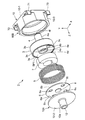
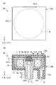
- FIG. 1 shows a perspective view of an external appearance of a solenoid valve (the whole is denoted by reference numeral 2) according to an embodiment of the present invention.
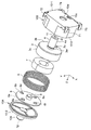
- FIG. 2 shows the electromagnetic valve 2 in an exploded state.
- FIG. 3 shows that FIG. 2 is viewed from another direction.
- XYZ orthogonal coordinates are also shown in FIGS. 1 to 3 and FIGS. 4 to 7 and 11 to 12 described later.
- the Z direction may be referred to as a thickness direction
- the XY direction may be referred to as a plane direction.
- the electromagnetic valve 2 includes a case 10 as a housing.
- the case 10 includes a lid case 10A disposed on one side in the thickness direction (+ Z side) and a main case 10B disposed on the opposite side in the thickness direction ( ⁇ Z side).
- the lid case 10A includes a disk-shaped second end wall 10-2 forming an outer wall, and a cylindrical portion 10a (fluid) protruding from the center of the second end wall 10-2 to the outside (+ Z side). And a second fluid inlet / outlet port 12 for passing the fluid.
- the main case 10B has a rectangular (in this example, square) plate-shaped first end wall 10-1 and a substantially cylindrical outer peripheral wall 10-3 connected to the first end wall 10-1. ing. As shown in FIG. 3, a through hole 10w into which a pole piece 4 described later is fitted is provided in the center of the first end wall 10-1. In addition, a through hole 10u through which a wiring (a lead wire (not shown)) passes is provided on one side (in this example, the side on the -Y side) of the first end wall 10-1. Connection terminals 71, 72, 73, and 74 (reference) made of metal (such as copper) are integrally provided at the four corners of the outer surface of the first end wall 10-1.
- the lid case 10A is formed by integrally molding a nonmagnetic plastic material.
- the main case 10B is formed by integrally molding (insert molding) a nonmagnetic plastic material together with the connection terminals 71, 72, 73, and 74.
- the second end wall 10-2 of the lid case 10A is welded to the outer peripheral wall 10-3 of the main case 10B.
- the present invention is not limited to this, and the second end wall 10-2 may be screwed to the outer peripheral wall 10-3.
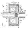
- a solenoid coil 7, a coil spring 5 as an urging portion, a diaphragm 6, and an elastic body 8 formed integrally with the diaphragm 6 are provided inside the case 10 of the electromagnetic valve 2, a yoke 3 and a pole piece 4 integrally attached perpendicularly to the yoke 3 (end plate portion 3 b).
- a solenoid coil 7, a coil spring 5 as an urging portion, a diaphragm 6, and an elastic body 8 formed integrally with the diaphragm 6 are provided inside the case 10 of the electromagnetic valve 2, a yoke 3 and a pole piece 4 integrally attached perpendicularly to the yoke 3 (end plate portion 3 b).
- the yoke 3 is connected to the end plate portion 3b having an annular (circular in this example) peripheral edge, and the peripheral edge of the end plate portion 3b, and on one side (+ Z side) of the end plate portion 3b. And a side plate portion 3c surrounding the adjacent space SP1 in a ring shape.
- a through hole 3w is provided in the center of the end plate portion 3b, and a pole piece 4 is fitted in the through hole 3w.
- a portion of the peripheral edge of the end plate portion 3b corresponding to the through hole 10u of the first end wall 10-1 of the main case 10B is provided with a through hole 3u through which wiring (lead wire not shown) is passed. ing.
- the shape of the peripheral edge of the end plate portion 3b of the yoke 3 is not limited to a circle, and may be a rounded square (a square with rounded corners). The same applies to the annular shape of the side wall portion of the side plate portion 3c.
- the outer diameter of the side plate portion 3c of the yoke 3 is set smaller than the inner diameter of the outer peripheral wall 10-3 of the main case 10B.
- the pole piece 4 has a substantially cylindrical shape as a whole.
- the pole piece 4 has a projection 4a that fits into the through-hole 3w of the yoke 3 and protrudes outside in the axial direction (Z direction), and a main portion having an outer diameter larger than the outer diameter of the projection 4a. 4b. That is, this pole piece 4 is orthogonal to the end plate portion 3b of the yoke 3 in one direction (from one end portion 4e existing in the space SP1 on one side (+ Z side) to the other end portion 4f on the opposite side ( ⁇ Z side) ( Z direction).
- the pole piece 4 has a recess 4d having a circular planar shape that opens toward the elastic body 8 of the diaphragm 6 at one end 4e.
- a circular opening 4o is opened at the bottom of the recess 4d.
- a circular first fluid inlet / outlet port 11 communicating with the opening 4 o through the pole piece 4 is provided at the other end portion 4 f of the pole piece 4.
- the yoke 3 and the pole piece 4 are each made of SUM24L (sulfur composite free cutting steel) which is a magnetic material.
- the protrusion 4a of the pole piece 4 is press-fitted into the through hole 3w of the yoke 3, so that the yoke 3 and the pole piece 4 are integrally formed.
- the magnetic resistance between the pole piece 4 and the yoke 3 is small, and the efficiency of the magnetic circuit using them as a path is increased.
- the airtightness between the pole piece 4 and the yoke 3 can be improved, and air leakage can be prevented.
- the yoke 3 and the pole piece 4 may be configured as a spatially continuous unit.
- the solenoid coil 7 has a compact cylindrical outer shape.
- the dimensions of the solenoid coil 7 are set such that the solenoid coil 7 can be accommodated in an annular space SP1 between the pole piece 4 and the side plate portion 3c of the yoke 3.
- a pair of lead wires extend from the solenoid coil 7.
- the coil spring 5 has a substantially cylindrical outline.
- the coil spring 5 is disposed along the annular space SP2 between the side plate portion 3c of the yoke 3 and the outer peripheral wall 10-3 of the main case 10B in the assembled state shown in FIG.
- the pole piece 4 is biased in a direction away from the one end 4e (that is, + Z direction).
- a biasing force f ⁇ b> 2 in which the coil spring 5 biases the diaphragm 6 is schematically indicated by an arrow.
- it can be simply comprised with components (namely, coil spring 5) with few energizing parts.
- the diaphragm 6 has a substantially disk-shaped outer shape.
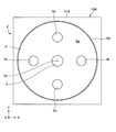
- FIG. 5 shows the planar shape of the diaphragm 6
- four circular through holes 6s, 6t, 6u, 6v are provided.
- fluid can flow through the through holes 6s, 6t, 6u, and 6v between the rear surface (surface facing the + Z side) 6a side and the inner surface (surface facing the -Z side) 6b side of the diaphragm 6. ing.
- the diaphragm 6 has a dimension extending over the annular edge 3 e of the side plate portion 3 c of the yoke 3.
- the outer diameter of the diaphragm 6 substantially matches the outer diameter of the coil spring 5.
- the diaphragm 6 is substantially disc-shaped as described above, and is made of permalloy (Ni—Fe alloy) as a magnetic material.
- the diaphragm 6 can be comprised lightly compared with a rod-shaped movable iron core, for example. In that case, when the posture (orientation) of the electromagnetic valve 2 changes in various directions with respect to the vertical direction, the characteristics (for example, the current-flow-current characteristic) are hardly affected by the posture of the electromagnetic valve 2.
- the diaphragm 6 has a substantially cylindrical elastic member for closing the opening 4 o opposite to the opening 4 o formed in the recess 4 d of the one end 4 e of the pole piece 4.
- the body 8 is attached integrally.
- the elastic body 8 is made of silicone rubber.
- the elastic body 8 may consist of other elastic materials (flexible material), such as nitrile rubber (NBR) and ethylene propylene diene rubber (EPDM).
- the outer diameter of the elastic body 8 is set larger than the diameter of the opening 4o and smaller than the inner diameter of the recess 4d. Thereby, the elastic body 8 can block
- the elastic body 8 is integrally attached to the diaphragm 6 by insert molding. Thereby, the diaphragm 6 and the elastic body 8 can be easily attached integrally.
- the invention is not limited to this, and the elastic body 8 may be attached to the diaphragm 6 by press-fitting, bonding, or the like.
- the solenoid coil 7 is accommodated in the annular space SP1 between the pole piece 4 and the side plate portion 3c of the yoke 3.
- a pair of lead wires (not shown) extending from the solenoid coil 7 are connected to the through hole 3u of the end plate portion 3b of the yoke 3 and the through hole 10u of the first end wall 10-1 of the main case 10B. And is pulled out of the main case 10B.
- a pair of lead wires drawn out are soldered one by one to any two of the four connection terminals 71, 72, 73, 74 provided on the outer surface of the first end wall 10-1. Attach.
- connection terminals 71, 72, 73, 74 are left as dummy terminals.
- the yoke 3 is bonded to the main case 10B, and the solenoid coil 7 is bonded to the yoke 3 in an airtight manner with an adhesive.
- the through hole 3u of the end plate portion 3b of the yoke 3 through which the pair of lead wires pass and / or the through hole 10u of the first end wall 10-1 of the main case 10B are filled with an adhesive. And get airtight.
- the coil spring 5 is accommodated in the annular space SP2 (see FIG.
- the diaphragm 6 is arranged from one side (+ Z side) of the coil spring 5 so as to face the end plate portion 3b of the yoke 3 through the space SP1. Further, while pushing the diaphragm 6 against the urging force f2 of the coil spring 5 with the lid case 10A, the second end wall 10-2 of the lid case 10A exceeds the outer peripheral wall 10-3 of the main case 10B. It is welded airtight by sonic welding. In this way, the electromagnetic valve 2 is assembled as shown in FIG.
- the case 10 is a sealed case, and the yoke 3 and the main part of the pole piece 4 with the protrusion 4 a (including the other end 4 f) of the pole piece 4 exposed to the outside. 4b, the solenoid coil 7, the diaphragm 6 (and the elastic body 8), and the coil spring 5 are collectively and airtightly covered.
- the first end wall 10-1 of the main case 10B is along the outer surface (the surface facing the -Z side) of the end plate portion 3b of the yoke 3, while the second end wall 10-2 of the lid case 10A is the diaphragm 6 It is in a state along the rear surface (surface facing the + Z side) 6a.
- the protrusion 4a of the pole piece 4 that forms the first fluid inlet / outlet 11 protrudes from the first end wall 10-1 to the outside, and the cylindrical portion 10a that forms the second fluid inlet / outlet 12 2 projecting outward from the end wall 10-2. Accordingly, the first fluid inlet / outlet port 11 and the second fluid inlet / outlet port 12 can be easily connected to, for example, the downstream side and the upstream side of the flow path so as to allow fluid flow. Thereby, this electromagnetic valve 2 can be easily inserted in the flow path.
- the biasing force of the coil spring 5 is generated by the magnetic force F0 generated by the solenoid coil 7 (the resultant force of the magnetic forces f0, f0,... Applied to each part of the diaphragm 6).
- the diaphragm 6 is formed on the pole piece 4 against the repulsive force f2 ′ (the resultant force of these f2 and f2 ′ is expressed as a drag force F2) received by the elastic body 8 from f2 and the recess 4d of the end 4e of the pole piece 4.
- the elastic body 8 can close the opening 4o of the one end portion 4e of the pole piece 4.
- the lines of magnetic force generated by the solenoid coil 7 are mainly the side plates of the yoke 3 as indicated by a two-dot chain line M in FIG. 3c reaches the periphery of the end plate portion 3b, reaches from the periphery of the end plate portion 3b through the end plate portion 3b to an orthogonal position between the end plate portion 3b and the pole piece 4, and passes through the pole piece 4 from this orthogonal position.
- the diaphragm 6 approaches the one end 4e of the pole piece 4, and the opening 4o can be closed by the elastic body 8.
- the solenoid valve 2 is in an open state or a closed state depending on whether the solenoid coil 7 is in a non-energized state (during operation) or whether the solenoid coil 7 is in a conduction state (during operation). be able to. Thereby, the flow of the fluid through the pole piece 4, that is, through the electromagnetic valve 2 can be allowed or blocked.
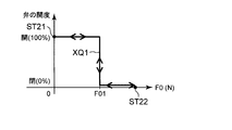
- FIG. 10 shows the relationship between the magnetic force F0 generated by the solenoid coil 7 and the opening of the valve for the electromagnetic valve 2.
- the opening degree of the valve is expressed as 100% when the valve is fully opened and 0% when the valve is fully closed. For simplicity, an intermediate state between the open state and the closed state of each valve will be ignored and described.
- the energization amount of the solenoid coil 7 is increased and the magnetic force F0 is increased as shown by the solid line XQ1
- the state shifts from the open state to the closed state at the magnetic force F01.
- the magnetic force F0 is temporarily stopped at a point ST22 where it slightly exceeds F01.
- the electromagnetic valve 2 when the energization amount of the solenoid coil 7 is decreased to reduce the magnetic force F0, the electromagnetic valve 2 moves backward on the solid line XQ1 and returns to the open state when the magnetic force F01 is almost reached. Then, the process returns to the first point ST21.
- the open / close state of the solenoid valve 2 there is an intermediate state in which the flow rate is controlled according to the energization amount of the solenoid between the closed state and the open state.
- the elastic body 8 of the diaphragm 6 approaches the opening 4 o of the one end 4 e of the pole piece 4. Thereby, a stable energization current (or drive voltage) versus flow rate characteristic can be obtained.
- the plate-like diaphragm 6 approaches the one end 4 e of the pole piece 4 in a posture facing the end plate 3 b of the yoke 3 in order to allow or block the fluid flow.
- it is configured to move in parallel in one direction (Z direction) in the direction of separation. That is, unlike the conventional example (in which the movable iron core is rod-shaped and moves along its longitudinal direction), in this solenoid valve 2, the plate-like diaphragm 6 is perpendicular to the plate surface of the diaphragm 6. Move in the direction (Z direction). Therefore, the size of the solenoid valve 2 can be reduced in one direction (Z direction) in which the diaphragm 6 moves. As a result, the electromagnetic valve 2 can be configured in a small size.
- the first and second end walls 10-1, 10-1, 10-2 are set by reducing the size of the case 10 from the first end wall 10-1 to the second end wall 10-2. It can have a flat outline along 10-2.
- Such an outer shape is suitable for mounting the electromagnetic valve 2 (case 10) along, for example, a wiring board and forming the electromagnetic valve 2 (case 10) and the wiring board together in a flat shape as a whole.
- the thickness (Z-direction dimension) H of the case 10 is set to about 2.5 mm.
- the planar dimension (XY dimension) W1, W2 of the case 10 is set to about 5.5 mm.
- the case 10 has a flat outer shape.
- the dimension in which the cylindrical portion 10a of the lid case 10A protrudes from the second end wall 10-2 to the + Z side is set to about 1.6 mm.
- the outer diameter and inner diameter of the cylindrical portion 10a are set to about 1.3 mm and about 0.8 mm, respectively.
- the dimension in which the protrusion 4a of the pole piece 4 protrudes from the first end wall 10-1 of the main case 10B to the -Z side is set to about 1.6 mm.
- the outer diameter and inner diameter of the protrusion 4a of the pole piece 4 are set to about 1.3 mm and about 0.5 mm, respectively.
- the solenoid valve 2 can be configured in a small size.
- the electromagnetic valve 2 can be reduced in weight.
- the solenoid valve 2 instead of the rod-like movable iron core of the conventional solenoid valve, the solenoid valve 2 includes a plate-like diaphragm 6 made of permalloy, so that the solenoid valve 2 can be reduced in weight. Even if the posture of the solenoid valve 2 changes variously with respect to the vertical direction, there is little change in characteristics (for example, current-flow characteristic versus flow characteristic). Therefore, the electromagnetic valve 2 can be opened and closed stably and reliably.
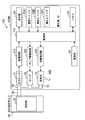
- FIG. 8 shows a schematic block configuration of an electronic sphygmomanometer (the whole is denoted by reference numeral 100) according to an embodiment of the present invention.
- the sphygmomanometer 100 roughly includes a cuff 20 attached to a measurement site such as a wrist or an upper arm, and a main body 100M.
- the cuff 20 includes a fluid bag 22 for pressing the measurement site.
- the fluid bag 22 and the main body 100M are connected by a flexible air tube 38 so that fluid can flow.
- the main body 100M includes a control unit 110, a display device 50, a memory 51 as a storage unit, an operation unit 52, a power supply unit 53, a pressure sensor 31, a pump 32, and an exhaust valve composed of the electromagnetic valve 2 described above.
- the valve 33 is mounted.
- the main body 100M includes an oscillation circuit 310 that converts the output from the pressure sensor 31 into a frequency, a pump drive circuit 320 that drives the pump 32, and a valve drive circuit 330 that drives the exhaust valve 33.
- the pressure sensor 31, the pump 32, and the exhaust valve 33 are connected to an air tube 38 through a common air pipe 39 provided in the main body 100M so that fluid can flow.
- the second fluid inlet / outlet 12 is connected in communication with the air pipe 39, and the first fluid inlet / outlet 11 is opened toward the atmosphere 900.
- the display device 50 includes a display, an indicator, and the like, and displays predetermined information (for example, blood pressure measurement result) according to a control signal from the control unit 110.
- the operation unit 52 includes a power switch 52A that receives an input of an instruction for turning the power supply unit 53 on (ON) or OFF (off), a measurement switch 52B for receiving an instruction to start blood pressure measurement, and an instruction to stop the measurement And a stop switch 52C.
- These switches 52 ⁇ / b> A, 52 ⁇ / b> B, and 52 ⁇ / b> C input an operation signal according to an instruction from the user to the control unit 110.
- the memory 51 is data of a program for controlling the sphygmomanometer 100, data used for controlling the sphygmomanometer 100, setting data for setting various functions of the sphygmomanometer 100, and data of blood pressure value measurement results Memorize etc.
- the memory 51 is used as a work memory when the program is executed.
- the control unit 110 includes a CPU (Central Processing Unit) and controls the overall operation of the sphygmomanometer 100. Specifically, the control unit 110 works as a pressure control unit according to a program for controlling the sphygmomanometer 100 stored in the memory 51, and in response to an operation signal from the operation unit 52, the pump 32 and the exhaust valve 33. The control which drives is performed. The control unit 110 also functions as a blood pressure calculation unit, calculates a blood pressure value, and controls the display 50 and the memory 51. A specific method for measuring blood pressure will be described later.
- CPU Central Processing Unit
- the power supply unit 53 supplies power to the control unit 110, the pressure sensor 31, the pump 32, the exhaust valve 33, the display 50, the memory 51, the oscillation circuit 310, the pump drive circuit 320, and the valve drive circuit 330.
- the pump 32 supplies air as a fluid to the fluid bag 22 in order to pressurize the pressure (cuff pressure) in the fluid bag 22 contained in the cuff 20.
- the exhaust valve 33 is opened and closed to discharge or enclose the air in the fluid bag 22 and control the cuff pressure.
- the pump drive circuit 320 drives the pump 32 based on a control signal given from the control unit 110.
- the valve drive circuit 330 opens and closes the exhaust valve 33 based on a control signal given from the control unit 110.
- the pressure sensor 31 and the oscillation circuit 310 function as a pressure detection unit that detects the cuff pressure.
- the pressure sensor 31 is, for example, a piezoresistive pressure sensor, and detects the pressure (cuff pressure) in the fluid bag 22 contained in the cuff 20 via the air pipe 39 and the air tube 38.
- the oscillation circuit 310 oscillates based on an electric signal value based on a change in electric resistance due to the piezoresistance effect from the pressure sensor 31 and controls a frequency signal having a frequency corresponding to the electric signal value of the pressure sensor 31. Output to the unit 110.
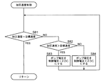
- FIG. 9A shows an operation flow when the user performs blood pressure measurement with the sphygmomanometer 100.
- control unit 110 When the user gives an instruction to start measurement with the operation unit 52 provided in the main body 100M with the cuff 20 attached to the measurement site, the control unit 110 performs initial setting (step S1 in FIG. 9A). Specifically, the control unit 110 initializes the processing memory area, turns off (stops) the pump 32, and opens the exhaust valve 33, thereby adjusting the pressure sensor 31 to 0 mmHg (atmospheric pressure to 0 mmHg). Set.)
- control unit 110 closes the exhaust valve 33 via the valve drive circuit 330 and then turns on (activates) the pump 32 via the pump drive circuit 320, and the cuff 20 (fluid bag 22). Pressurization is started (step S2).
- the controller 110 controls the pressurization speed based on the output of the pressure sensor 31 while supplying air from the pump 32 to the fluid bag 22 through the air pipe 39 and the air tube 38 (step S3).
- the controller 110 determines whether or not the pressurization speed matches the target speed (step S81 in FIG. 9B).
- the process directly returns to the flow of FIG. 9A.
- the process proceeds to step S82 in FIG. 9B to determine whether the pressurization speed is greater than the target speed.
- step S82 if the pressurization speed is larger than the target speed (YES in step S82), the drive voltage of the pump 32 is decreased from the current control voltage by a fixed value ⁇ [V] (step S83). On the other hand, if the pressurization speed is smaller than the target speed (NO in step S82), the drive voltage of the pump 32 is increased from the current control voltage by a fixed value ⁇ [V] (step S84). Thereafter, the flow returns to the flow of FIG. 9A.
- step S4 of FIG. 9A the control unit 110 operates as a blood pressure calculation unit, and based on the pulse wave signal acquired at this time (the fluctuation component due to the pulse wave included in the output of the pressure sensor 31).
- the blood pressure values (systolic blood pressure SBP (systolic blood pressure) and diastolic blood pressure DBP (diastolic blood pressure)) are tried to be calculated by a known oscillometric method.
- step S5 if the blood pressure value cannot be calculated yet due to lack of data (NO in step S5), the cuff pressure has reached the upper limit pressure (for example, 300 mmHg is determined in advance for safety). Unless otherwise specified, the processes in steps S3 to S5 are repeated.
- the upper limit pressure for example, 300 mmHg is determined in advance for safety.
- the control unit 110 displays the measurement result of the blood pressure value on the display 50. Further, the control unit 110 performs control to turn off the pump 32, open the exhaust valve 33 (step S6), and exhaust the air in the cuff 20 (fluid bag 22).
- control unit 110 displays the calculated blood pressure value on the display device 50 (step S7), and performs control to store the blood pressure value in the memory 51.
- the blood pressure calculation may be performed not during the pressurization process of the cuff 20 (fluid bag 22) but during the decompression process.
- the exhaust valve 33 is composed of a solenoid valve 2 that is small and lightweight. Therefore, the main body 100M, and thus the entire blood pressure monitor 100, can be configured to be small and lightweight. Even if the posture of the exhaust valve 33 (solenoid valve 2) changes variously with respect to the vertical direction, there is little change in characteristics (for example, energization current vs. flow characteristics). Therefore, the exhaust valve 33 can be opened and closed stably and reliably, and thus the operation of the sphygmomanometer 100 can be stabilized.
- the second fluid inlet / outlet 12 of the electromagnetic valve 2 is configured by the cylindrical portion 10a protruding outward (+ Z side) from the second end wall 10-2 of the lid case 10A. In that case, it becomes easy to insert the electromagnetic valve 2 in the straight flow path.
- the present invention is not limited to this.
- FIGS. 11A and 11B show an example of an electromagnetic valve 2D obtained by modifying the case 10 of the electromagnetic valve 2 described above.
- FIG. 11A shows the electromagnetic valve 2D viewed from the + Z side.
- FIG. 11B shows a cross-sectional structure viewed from the lower side ( ⁇ Y side) in FIG.
- the cylindrical portion 10b forming the second fluid inlet / outlet 12 is disposed so as to protrude from the outer peripheral wall 10-3 of the main case 10B to the outside (+ X side).
- the other points are configured in the same manner as the solenoid valve 2 (in FIG. 11B, for simplicity, the structure of the diaphragm 6 is simplified and illustrated as compared with FIGS. 4, 6, and 7. (This also applies to FIG. 12B described later.)
- the diaphragm 6 approaches the one end 4e of the pole piece 4 and the opening 4o is closed by the elastic body 8 as in the electromagnetic valve 2.
- the cylindrical portion 10b forming the second fluid inlet / outlet 12 is prevented from projecting to the outside (+ Z side) from the second end wall 10-2 of the lid case 10A.
- a solenoid valve can be reduced in thickness.
- the main case 10B is attached along the upper surface of the wiring board (not shown), and the protrusion 4a that forms the first fluid inlet / outlet 11 extends downward through the wiring board, so that the electromagnetic valve 2D
- the wiring board and the wiring board can be configured flat as a whole.
- FIG. 12A and 12B show another example of an electromagnetic valve 2E obtained by modifying the case 10 of the electromagnetic valve 2.
- FIG. 12A shows the electromagnetic valve 2E viewed from the + Z side.
- FIG. 12B shows a cross-sectional structure viewed from the lower side ( ⁇ Y side) in FIG.
- the cylindrical portion 10c forming the second fluid inlet / outlet 12 is disposed so as to protrude from the first end wall 10-1 of the main case 10B to the outside ( ⁇ Z side).
- the other points are configured in the same manner as the electromagnetic valve 2.
- the diaphragm 6 approaches the one end 4e of the pole piece 4 and the opening 4o is closed by the elastic body 8 as in the electromagnetic valve 2.
- the cylindrical portion 10c forming the second fluid inlet / outlet 12 protrudes from the second end wall 10-2 of the lid case 10A to the outside (+ Z side). Can be avoided. Thereby, a solenoid valve can be reduced in thickness. Further, in the electromagnetic valve 2E, the cylindrical portion 10c forming the second fluid inlet / outlet 12 can be protruded in the same direction (the ⁇ Z direction) as the protruding portion 4a forming the first fluid inlet / outlet 11.
- the main case 10B is attached along the upper surface of a wiring board (not shown), and both the cylindrical portion 10c and the protruding portion 4a extend downward through the wiring board, so that the electromagnetic valve 2E and the wiring Together with the substrate, it can be configured flat as a whole.
- the flow path connected to the electromagnetic valve 2E can be disposed only below the wiring board.
- the electromagnetic valve of the present invention is applied to a sphygmomanometer, but the present invention is not limited to this.
- the electromagnetic valve of the present invention can be applied to various devices other than a blood pressure monitor.
- the solenoid valve of this invention can be applied also to the apparatus containing the function part which performs a blood pressure measurement function and other various functions.
- the device can be configured to be small and lightweight.
- the solenoid valve can be opened and closed stably and reliably. Therefore, the operation of the device can be stabilized.
Landscapes
- Health & Medical Sciences (AREA)
- Life Sciences & Earth Sciences (AREA)
- Engineering & Computer Science (AREA)
- Cardiology (AREA)
- Vascular Medicine (AREA)
- General Engineering & Computer Science (AREA)
- Biophysics (AREA)
- Molecular Biology (AREA)
- Physics & Mathematics (AREA)
- Veterinary Medicine (AREA)
- Public Health (AREA)
- Pathology (AREA)
- Biomedical Technology (AREA)
- Heart & Thoracic Surgery (AREA)
- Medical Informatics (AREA)
- Physiology (AREA)
- Surgery (AREA)
- Animal Behavior & Ethology (AREA)
- General Health & Medical Sciences (AREA)
- Ophthalmology & Optometry (AREA)
- Mechanical Engineering (AREA)
- Magnetically Actuated Valves (AREA)
- Measuring Pulse, Heart Rate, Blood Pressure Or Blood Flow (AREA)
Priority Applications (4)
| Application Number | Priority Date | Filing Date | Title |
|---|---|---|---|
| DE112019000772.6T DE112019000772T5 (de) | 2018-02-13 | 2019-01-24 | Elektronisches ventil, sphygmomanometer und gerät |
| BR112020016367-8A BR112020016367B1 (pt) | 2018-02-13 | 2019-01-24 | Válvula eletrônica, esfigmomanômetro, e, aparelho capaz de medir pressão arterial de uma parte a ser medida |
| CN201980013083.9A CN111712661B (zh) | 2018-02-13 | 2019-01-24 | 电磁阀、血压计以及设备 |
| US16/942,845 US12171532B2 (en) | 2018-02-13 | 2020-07-30 | Electronic valve, sphygmomanometer, and apparatus |
Applications Claiming Priority (2)
| Application Number | Priority Date | Filing Date | Title |
|---|---|---|---|
| JP2018-023421 | 2018-02-13 | ||
| JP2018023421A JP6989405B2 (ja) | 2018-02-13 | 2018-02-13 | 電磁弁、血圧計および機器 |
Related Child Applications (1)
| Application Number | Title | Priority Date | Filing Date |
|---|---|---|---|
| US16/942,845 Continuation US12171532B2 (en) | 2018-02-13 | 2020-07-30 | Electronic valve, sphygmomanometer, and apparatus |
Publications (1)
| Publication Number | Publication Date |
|---|---|
| WO2019159640A1 true WO2019159640A1 (ja) | 2019-08-22 |
Family
ID=67619391
Family Applications (1)
| Application Number | Title | Priority Date | Filing Date |
|---|---|---|---|
| PCT/JP2019/002310 Ceased WO2019159640A1 (ja) | 2018-02-13 | 2019-01-24 | 電磁弁、血圧計および機器 |
Country Status (5)
| Country | Link |
|---|---|
| US (1) | US12171532B2 (enExample) |
| JP (1) | JP6989405B2 (enExample) |
| CN (1) | CN111712661B (enExample) |
| DE (1) | DE112019000772T5 (enExample) |
| WO (1) | WO2019159640A1 (enExample) |
Families Citing this family (7)
| Publication number | Priority date | Publication date | Assignee | Title |
|---|---|---|---|---|
| KR20220142709A (ko) * | 2021-04-15 | 2022-10-24 | 한화에어로스페이스 주식회사 | 방폭 구조를 구비하는 솔레노이드 밸브, 연료 공급 시스템 및 그 제조방법 |
| US11674611B2 (en) * | 2021-04-22 | 2023-06-13 | Fisher Controls International Llc | Wear-resistant electro-pneumatic converters |
| CN114396503B (zh) * | 2022-02-25 | 2025-02-28 | 惠州市盈毅电机有限公司 | 一种簧片型微电磁阀 |
| CN117287549A (zh) * | 2022-06-20 | 2023-12-26 | 华为技术有限公司 | 一种电磁阀及设备 |
| EP4403101A1 (en) * | 2023-01-20 | 2024-07-24 | Shenzhen Jamr Technology Co., Ltd. | Air control mechanism and sphygmomanometer |
| CN118924270B (zh) * | 2023-05-11 | 2025-09-05 | 华为技术有限公司 | 电磁阀及可穿戴设备 |
| CN118361576A (zh) * | 2024-04-29 | 2024-07-19 | 采埃孚商用车系统(青岛)有限公司 | 电磁阀及其装配方法 |
Citations (2)
| Publication number | Priority date | Publication date | Assignee | Title |
|---|---|---|---|---|
| US3433256A (en) * | 1965-03-11 | 1969-03-18 | Buehler Ag Geb | Electrohydraulic valve |
| US4848727A (en) * | 1987-03-30 | 1989-07-18 | Koganei Ltd. | Solenoid valve |
Family Cites Families (15)
| Publication number | Priority date | Publication date | Assignee | Title |
|---|---|---|---|---|
| GB1164043A (en) * | 1966-12-30 | 1969-09-10 | United Aircraft Corp | Electromechanical Actuator |
| DE3424913A1 (de) * | 1984-07-06 | 1986-01-16 | Robert Bosch Gmbh, 7000 Stuttgart | Elektromagnetisches ventil |
| DE3704504A1 (de) * | 1987-02-13 | 1988-08-25 | Siegfried Schertler | Ventil |
| US4858886A (en) * | 1987-03-31 | 1989-08-22 | Aisin Seiki Kabushiki Kaisha | Electromagnetic valve |
| JPH08203730A (ja) | 1995-01-26 | 1996-08-09 | Matsushita Electric Works Ltd | ソレノイド |
| US6948697B2 (en) * | 2000-02-29 | 2005-09-27 | Arichell Technologies, Inc. | Apparatus and method for controlling fluid flow |
| JP3385262B2 (ja) * | 2000-05-29 | 2003-03-10 | 日本コーリン株式会社 | 血圧測定装置 |
| JP2001346769A (ja) * | 2000-06-09 | 2001-12-18 | Nippon Colin Co Ltd | 循環状態監視装置 |
| JP2002034933A (ja) * | 2000-07-26 | 2002-02-05 | Nippon Colin Co Ltd | 術後回復状態評価装置 |
| JP2002221279A (ja) * | 2001-01-25 | 2002-08-09 | Foster Electric Co Ltd | 流量コントロール弁 |
| JP2006242232A (ja) * | 2005-03-01 | 2006-09-14 | Nippon Seimitsu Sokki Kk | 電動排気弁及び血圧計 |
| US7427267B2 (en) * | 2006-03-06 | 2008-09-23 | Welch Allyn, Inc. | Blood pressure determining method |
| JP4943748B2 (ja) * | 2006-06-27 | 2012-05-30 | テルモ株式会社 | 血圧測定装置、その測定方法及び記憶媒体 |
| US8047997B2 (en) * | 2007-08-27 | 2011-11-01 | General Electric Company | Non-invasive blood pressure monitor apparatus and system |
| JP2016138573A (ja) * | 2015-01-26 | 2016-08-04 | オムロンヘルスケア株式会社 | 電磁弁およびそれを備えた電子血圧計 |
-
2018
- 2018-02-13 JP JP2018023421A patent/JP6989405B2/ja active Active
-
2019
- 2019-01-24 WO PCT/JP2019/002310 patent/WO2019159640A1/ja not_active Ceased
- 2019-01-24 CN CN201980013083.9A patent/CN111712661B/zh active Active
- 2019-01-24 DE DE112019000772.6T patent/DE112019000772T5/de active Granted
-
2020
- 2020-07-30 US US16/942,845 patent/US12171532B2/en active Active
Patent Citations (2)
| Publication number | Priority date | Publication date | Assignee | Title |
|---|---|---|---|---|
| US3433256A (en) * | 1965-03-11 | 1969-03-18 | Buehler Ag Geb | Electrohydraulic valve |
| US4848727A (en) * | 1987-03-30 | 1989-07-18 | Koganei Ltd. | Solenoid valve |
Also Published As
| Publication number | Publication date |
|---|---|
| JP2019138403A (ja) | 2019-08-22 |
| DE112019000772T5 (de) | 2020-10-29 |
| US12171532B2 (en) | 2024-12-24 |
| US20200352454A1 (en) | 2020-11-12 |
| JP6989405B2 (ja) | 2022-01-05 |
| BR112020016367A2 (pt) | 2020-12-15 |
| CN111712661A (zh) | 2020-09-25 |
| CN111712661B (zh) | 2022-08-02 |
Similar Documents
| Publication | Publication Date | Title |
|---|---|---|
| WO2019159640A1 (ja) | 電磁弁、血圧計および機器 | |
| JP2019138403A5 (enExample) | ||
| US10502328B2 (en) | Valve and fluid control appratus | |
| WO2019159639A1 (ja) | 電磁弁、血圧計、血圧測定方法、および機器 | |
| US8905940B2 (en) | Flow rate control valve and blood pressure information measurement device including the same | |
| CN100585239C (zh) | 电动排气阀及血压计 | |
| US11293427B2 (en) | Valve, and fluid control device including valve | |
| JP6338017B2 (ja) | 吸引装置 | |
| CN110693477B (zh) | 流量控制阀以及具有其的血压信息测量装置 | |
| JP2015111562A (ja) | スイッチ構造および防爆機器 | |
| JP5364592B2 (ja) | ソレノイドバルブ | |
| JP6805558B2 (ja) | 流量制御弁およびその製造方法、ならびに血圧情報測定装置 | |
| WO2008038759A1 (en) | Speaker | |
| EP3289259B1 (en) | Low profile miniature solenoid proportional valve | |
| CN214093239U (zh) | 一种透气阀及便携式电子装置 | |
| JPS6376969A (ja) | 切換弁 | |
| JP2006242232A (ja) | 電動排気弁及び血圧計 | |
| JP6790467B2 (ja) | 流量制御弁および血圧情報測定装置 | |
| JP2020008032A (ja) | 流体通路開閉装置、流量制御装置および血圧計 | |
| CN213783763U (zh) | 一种便携电子装置及其可穿戴电子装置 | |
| JP6329781B2 (ja) | ソレノイド装置 | |
| JP5006538B2 (ja) | マイクロポンプおよび駆動体 | |
| JP2016138573A (ja) | 電磁弁およびそれを備えた電子血圧計 | |
| CN119353460A (zh) | 透气阀及便携式电子装置 | |
| BR112020016367B1 (pt) | Válvula eletrônica, esfigmomanômetro, e, aparelho capaz de medir pressão arterial de uma parte a ser medida |
Legal Events
| Date | Code | Title | Description |
|---|---|---|---|
| 121 | Ep: the epo has been informed by wipo that ep was designated in this application |
Ref document number: 19754411 Country of ref document: EP Kind code of ref document: A1 |
|
| DPE1 | Request for preliminary examination filed after expiration of 19th month from priority date (pct application filed from 20040101) | ||
| REG | Reference to national code |
Ref country code: BR Ref legal event code: B01A Ref document number: 112020016367 Country of ref document: BR |
|
| ENP | Entry into the national phase |
Ref document number: 112020016367 Country of ref document: BR Kind code of ref document: A2 Effective date: 20200812 |
|
| 122 | Ep: pct application non-entry in european phase |
Ref document number: 19754411 Country of ref document: EP Kind code of ref document: A1 |