WO2019159508A1 - 先端カバーおよび挿入機器 - Google Patents
先端カバーおよび挿入機器 Download PDFInfo
- Publication number
- WO2019159508A1 WO2019159508A1 PCT/JP2018/045084 JP2018045084W WO2019159508A1 WO 2019159508 A1 WO2019159508 A1 WO 2019159508A1 JP 2018045084 W JP2018045084 W JP 2018045084W WO 2019159508 A1 WO2019159508 A1 WO 2019159508A1
- Authority
- WO
- WIPO (PCT)
- Prior art keywords
- cover
- tip
- distal end
- modification
- tip cover
- Prior art date
- Legal status (The legal status is an assumption and is not a legal conclusion. Google has not performed a legal analysis and makes no representation as to the accuracy of the status listed.)
- Ceased
Links
Images











Classifications
-
- A—HUMAN NECESSITIES
- A61—MEDICAL OR VETERINARY SCIENCE; HYGIENE
- A61B—DIAGNOSIS; SURGERY; IDENTIFICATION
- A61B1/00—Instruments for performing medical examinations of the interior of cavities or tubes of the body by visual or photographical inspection, e.g. endoscopes; Illuminating arrangements therefor
-
- A—HUMAN NECESSITIES
- A61—MEDICAL OR VETERINARY SCIENCE; HYGIENE
- A61B—DIAGNOSIS; SURGERY; IDENTIFICATION
- A61B1/00—Instruments for performing medical examinations of the interior of cavities or tubes of the body by visual or photographical inspection, e.g. endoscopes; Illuminating arrangements therefor
- A61B1/012—Instruments for performing medical examinations of the interior of cavities or tubes of the body by visual or photographical inspection, e.g. endoscopes; Illuminating arrangements therefor characterised by internal passages or accessories therefor
- A61B1/018—Instruments for performing medical examinations of the interior of cavities or tubes of the body by visual or photographical inspection, e.g. endoscopes; Illuminating arrangements therefor characterised by internal passages or accessories therefor for receiving instruments
-
- G—PHYSICS
- G02—OPTICS
- G02B—OPTICAL ELEMENTS, SYSTEMS OR APPARATUS
- G02B23/00—Telescopes, e.g. binoculars; Periscopes; Instruments for viewing the inside of hollow bodies; Viewfinders; Optical aiming or sighting devices
- G02B23/24—Instruments or systems for viewing the inside of hollow bodies, e.g. fibrescopes
Definitions
- the present invention relates to a distal end cover and an insertion device provided at the distal end portion of an endoscope in which a treatment instrument capable of performing high-frequency therapy or the like is used.
- endoscopes that can observe organs in a body cavity and the like by inserting an elongated insertion portion into the body cavity are widely used.
- an endoscope or the like in which a solid-state imaging device such as a charge coupled device (CCD) is provided at the imaging unit at the front or rear end of the endoscope insertion unit is used. It has been.
- CCD charge coupled device
- a signal output from an image sensor provided in the endoscope is converted into a video signal by an image processing apparatus which is an external device of an endoscope separate from an electronic endoscope, an external camera, etc., and is output to a monitor.
- the electronic endoscope configured separately and the image processing apparatus are connected via an endoscope connector.
- a distal end cover is disposed at the distal end portion of the insertion portion.
- Japanese Patent Application Laid-Open No. 9-075295 discloses an endoscope technique in which the tip cover can be easily removed and there is no fear of reusing the used tip cover.
- an endoscope may treat a diseased part in the body by deriving a high-frequency treatment tool from the distal end of the insertion part.
- a high-frequency treatment tool from the distal end of the insertion part.
- the tip cover that covers the tip portion of a conventional endoscope is deformed by an external force, the insulating property of the deformed portion is lowered, and high-frequency current from the high-frequency treatment tool may leak from the tip portion. was there.
- the present invention has been made in view of the above circumstances, and improves the insulating property of the distal end portion of the insertion portion inserted into the body so that a high-frequency current may leak to the outside during treatment with the high-frequency treatment instrument.
- An object is to provide a tip cover and an insertion device to prevent.
- the distal end cover is a distal end cover that is attached to the distal end configuration portion provided at the distal end portion of the insertion portion that is inserted into the body, has electrical insulation, and is attached to and detached from the distal end configuration portion.
- An insertion device is a distal end cover attached to a distal end configuration portion provided at a distal end portion of an insertion portion to be inserted into a body, and has electrical insulation, and is attached to and detached from the distal end configuration portion.
- a front end cover including the first cover is attached to the front end of the insertion portion.
- the side view which shows the structure of the endoscope of this invention The perspective view which shows the structure of the front-end
- subjected Sectional drawing which shows the structure of the front-end
- Sectional drawing which shows the structure of the front-end
- the perspective view which shows the structure of the front-end
- the exploded perspective view which shows the front-end
- an aspect of an endoscope will be described as an example.
- the drawings based on each embodiment are schematic, and the relationship between the thickness and width of each part, the thickness ratio of each part, and the like are different from the actual ones. It should be noted that the drawings may include portions having different dimensional relationships and ratios between the drawings.
- the endoscope in the following description of the configuration will be described taking as an example a so-called flexible endoscope having a flexible insertion portion for insertion into an upper or lower digestive organ of a living body, but is not limited thereto.
- the technique can also be applied to a so-called rigid endoscope having a hard insertion portion used for surgery.
- FIG. 1 is a side view showing the configuration of the endoscope
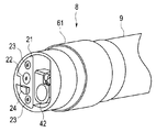
- FIG. 2 is a perspective view showing the configuration of the distal end portion of the insertion portion
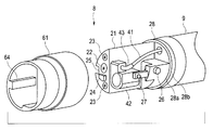
- FIG. 3 is a perspective view showing the configuration of the distal end portion with the distal end cover removed.
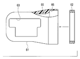
- 4 is a partial cross-sectional view showing the configuration of the tip cover and the rubber cover
- FIG. 5 is a cross-sectional view showing the configuration of the tip cover provided with the rubber cover
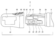
- FIG. 6 shows the configuration of the tip portion to which the tip cover is attached.
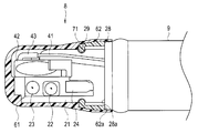
- FIG. 7 is a sectional view showing a configuration of the distal end portion to which the distal end cover is attached
- FIG. 8 is a sectional view showing the distal end portion in a state where the high-frequency treatment instrument raised by the raising base is led out.
- the endoscope 2 that is the insertion device of the present embodiment has an insertion portion 5 that is inserted into the body, an operation portion 6, and a universal cable 7.
- the insertion portion 5 is an elongated long member that is inserted into the observation target site from the distal end side in the longitudinal axis direction.
- the insertion portion 5 is configured by connecting a distal end portion 8, a bending portion 9, and a flexible tube portion 10.
- the distal end portion 8 incorporates an illumination optical system including a light guide and an imaging optical system including an imaging device, and a distal end surface is provided with a suction port that also serves as a nozzle and a treatment instrument outlet (both are not provided here). (Illustrated).
- the distal end portion 8 is provided with an observation window and an illumination window having a predetermined angle with respect to the insertion direction of the insertion portion 5, and serves as a direction conversion portion that raises the treatment instrument and converts it into the observation direction.
- An elevator 42 that is a movable part is disposed.
- the elevator 42 is connected to an elevator operating wire (hereinafter simply abbreviated as a wire) 41 as a pulling / relaxing member which is a long member inserted into the insertion portion 5 and the operation portion 6.
- a wire 41 as a pulling / relaxing member which is a long member inserted into the insertion portion 5 and the operation portion 6.
- the wire 41 is pulled and relaxed, the raising and lowering operation of the raising base 42 is performed. Note that the wire 41 is pulled or loosened by operating the elevator base operating lever 16.
- the bending portion 9 is configured to be freely bent in, for example, four directions, up, down, left, and right.
- the flexible tube portion 10 is a long and flexible tubular member.
- the operation unit 6 includes a gripping portion 6a, the gripping portion 6a is connected to the proximal end portion of the insertion portion 5, and a treatment instrument insertion port 6b is provided.
- the operation unit 6 is provided with a bending operation unit 11, an air / water supply button 13, a suction button 14, a cleaning tube attachment base 15, and the like. Further, the operation unit 6 is provided with a raising base operation lever 16 as an operation member.
- the bending operation unit 11 includes a bending operation knob 11a for performing the bending operation of the bending unit 9 of the insertion unit 5, and a fixing lever 11b for fixing the bending operation knob 11a at a desired rotation position. .
- the universal cable 7 is extended from the side surface of the operation unit 6. An end of the universal cable 7 is provided with an endoscope connector 30 connected to a light source device that is an external device.
- the endoscope connector 30 has a signal transmission cable 33 extending from the side. On the other end side of the signal transmission cable 33, an electrical connector 34 connected to the video processor is provided.
- the distal end portion 8 of the insertion portion 5 is provided with a distal end constituting portion 21 formed of a metal such as stainless steel.
- a raising base 42 made of a metal such as stainless steel is rotatably disposed.
- the distal end component 21 is provided with an observation window 22 and an illumination window 23 on one side surface orthogonal to the insertion axis X shown in FIG.
- the tip component part 21 is provided with a nozzle 24 for supplying air and water toward the observation window 22 and the illumination window 23.
- An insulating ring 28 which is a non-conductive first insulating member made of non-metal such as resin or ceramic, is provided on the outer periphery of the base end of the tip component 21.
- the elevator 42 is rotatably provided and is pivotally supported by the tip component portion 21 by a rotation shaft 27.
- the raising base 42 is connected to one side by a connecting body 43 formed by refracting the wire 41, and undulates around the rotation shaft 27 by a pulling / relaxing operation of the wire 41.
- a tip cover 61 which is a first cover formed from a synthetic resin such as an elastic-plastic material having electrical insulation, is detachably attached to the tip constituent portion 21.
- the tip cover 61 is mounted so as to cover the tip constituent portion 21.
- the restriction convex part 64 provided on the inner peripheral surface of the tip cover 61 is engaged with the restriction concave part 25 formed in the tip constituent part 21. Thereby, the mounting position of the tip cover 61 to the tip constituent portion 21 is defined.
- the front end cover 61 is an engaging portion formed on the inner peripheral portion of the convex locking pin 26 that is an engaging portion provided so as to protrude from the side portion of the tip constituting portion 21.
- the stop recess 65 (see FIGS. 4 and 5) engages and is fixedly attached to the tip constituting portion 21.
- the tip cover 61 has an opening 63 that exposes the observation window 22 and the illumination window 23 and leads out the treatment tool 100 that is raised and lowered by the raising table 42.
- the front end cover 61 is formed with a step portion 66 in the circumferential direction inside the base end, and the step portion 66 is an elastic second cover having electrical insulation.
- a ring-shaped rubber cover 62 as an insulating member 2 is adhered.
- a rubber cover 62 that is an insulating member is disposed around the entire inner periphery of the base end of the tip cover 61.
- the rubber cover 62 has a minimum inner diameter of approximately 14 mm or less, and is formed of rubber or the like that is softer than the tip cover 61.
- the distal end cover 61 covers the insulating ring 28 provided on the outer periphery of the proximal end of the distal end configuration portion 21 when the proximal end portion is attached to the distal end configuration portion 21.
- the entire circumference of the base end surface 62 a of the rubber cover 62 is in close contact with the entire circumference of the distal end surface 28 a of the insulating ring 28.
- the rubber cover 62 is in a state of being kept watertight by being in close contact with the joint portion with the insulating ring 28.
- the endoscope 1 configured as described above has a high-frequency current E that is generated at the distal end component during high-frequency treatment using a high-frequency treatment instrument 100 such as a high-frequency electric knife raised by a raising table 42. Even if it flows to 21, the rubber cover 62 of the tip cover 61 and the insulating ring 28 of the tip component 21 are in close contact with each other, and the possibility of flowing to the outside of the insertion portion 5 can be prevented.
- the distal end cover 61 is formed of an elastic-plastic member even when an external force is applied to the proximal end portion, and is not easily deformed due to the thickness of the rubber cover 62, so that the rubber cover 62 and the insulating ring 28 are in close contact with each other. Is maintained.
- the endoscope 1 is provided with the distal end configuration portion provided in the distal end portion 8 when the high-frequency treatment instrument 100 is led out from the distal end portion 8 of the insertion portion 5 to treat the affected area in the body.
- the tip cover 61 that covers the member 21 can prevent the high-frequency current E from the high-frequency treatment instrument 100 from leaking outside from the tip portion 8 without lowering the insulation.
- the endoscope 1 can improve the insulating property of the distal end portion 8 of the insertion portion 5 and prevent the possibility that the high-frequency current E leaks to the outside during the treatment with the high-frequency treatment instrument 100.
- FIG. 9 is a partial cross-sectional view showing a joined state of the rubber cover to the tip cover of the first modification.
- a concave circumferential groove 67 may be formed in a stepped portion 66 at the proximal end portion of the distal end cover 61, and the rubber cover 62 may be bonded to the circumferential groove 67.
- the rubber cover 62 cannot remove
- FIG. 10 is a partial cross-sectional view showing a joined state of the rubber cover to the tip cover of the second modified example.
- irregularities 68 may be formed on the stepped portion 66 of the proximal end portion of the tip cover 61, and a rubber cover 62 having an outer peripheral surface similar to the irregularities 68 may be bonded. Thereby, it can be set as the structure which the rubber cover 62 cannot remove
- FIG. 11 is a cross-sectional view showing the configuration of the tip portion to which the tip cover of the third modified example is attached.
- the rubber cover 62 may be formed in two colors on the base end outer periphery of the tip cover 61. Further, a part of the rubber cover 62 may be exposed on the outer peripheral surface of the tip cover 61.
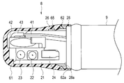
- FIG. 12 is a cross-sectional view showing the configuration of the tip portion to which the tip cover of the fourth modified example is attached.
- the rubber cover 62 may be provided at the proximal inner peripheral portion of the distal end cover 61 so that the inner peripheral surface 62 b is in close contact with the outer peripheral surface 28 b of the insulating ring 28 of the distal end constituting portion 21. .
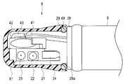
- FIG. 13 is sectional drawing which shows the structure of the front-end
- an O-ring 69 that is in close contact with the entire periphery of the distal end surface 28 a of the insulating ring 28 may be provided on the inner peripheral portion of the proximal end of the distal end cover 61.
- a locking recess 29 into which the O-ring 69 of the tip cover 61 is engaged is formed in the tip component portion 21 so that the tip cover 61 is mounted and fixed to the tip component portion 21. Also good.
- FIG. 14 is a cross-sectional view showing the configuration of the tip end portion to which the tip cover of the sixth modified example is attached.
- a convex portion 71 protruding in the inner diameter direction is provided at the distal end portion of the rubber cover 62, and a locking concave portion 29 into which the convex portion 71 is engaged is provided in the distal end constituting portion 21 instead of the locking pin 26.
- the tip cover 61 may be mounted and fixed to the tip constituent portion 21.
- FIG. 15 is a cross-sectional view showing the configuration of the tip end portion to which the tip cover of the seventh modified example is attached.
- a convex portion 71 a that protrudes in the inner diameter direction is provided at the distal end portion of the rubber cover 62, and a protruding portion 72 that is formed symmetrically adjacent to the convex portion 71 a is formed on the inner peripheral surface of the distal end cover 61.
- a locking recess 29 in which the protrusion 71 a and the protrusion 72 are engaged is formed in the tip component 21 instead of the locking pin 26 so that the tip cover 61 is attached and fixed to the tip component 21. It may be.
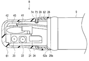
- FIG. 16 is a cross-sectional view showing the configuration of the tip portion to which the tip cover of the eighth modified example is attached.
- a protrusion 73 is formed on the inner peripheral surface of the tip cover 61, and a protrusion 74 covering the protrusion 73 is formed on the rubber cover 62, and this protrusion 74 is engaged.
- a locking recess 29 may be formed in the tip component 21 instead of the locking pin 26 so that the tip cover 61 is mounted and fixed to the tip component 21.
- FIG. 17 is a cross-sectional view showing the configuration of the tip end portion to which the tip cover of the ninth modification is attached. As shown in FIG. 17, a hole 81 that can accommodate a deformed rubber cover 62 is formed in the tip cover 61, and the locking pin 26 of the tip constituent portion 21 presses against the rubber cover 62 so that the tip cover 61 has a tip configuration. It may be attached and fixed to the portion 21.
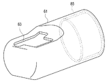
- FIG. 18 is a perspective view showing the configuration of the tip cover of the tenth modification
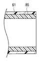
- FIG. 19 is a cross-sectional view of the first form of the proximal end portion of the tip cover of the tenth modification
- FIG. 20 is the tenth modification.
- FIG. 21 is a sectional view of the third embodiment of the base end portion of the tip cover of the tenth modification
- FIG. 22 is a sectional view of the tenth modification of the base end portion of the tip cover of the example.
- FIG. 23 is a sectional view of the fourth embodiment of the proximal end portion of the distal end cover
- FIG. 23 is a sectional view of the fifth embodiment of the proximal end portion of the distal end cover of the tenth modification.
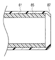
- the rubber cover 85 may be a tube body having a predetermined length. As shown in FIG. 20, a tapered surface 86 may be formed at the proximal end portion of the distal end cover 61. In addition, as shown in FIG. 21, the base end portion of the distal end cover 61 may be formed with a small diameter portion 87 that is slanted in the inner diameter direction.
- the rubber cover 85 may protrude from the proximal end of the distal end cover 61.
- the rubber cover 85 may be formed with a protruding portion 88 in close contact with the outer peripheral surface of the tip constituting portion 21 in the circumferential direction of the inner peripheral portion.
- FIG. 24 is an exploded perspective view showing the distal end portion of the endoscope in which the visual field direction of the eleventh modified example is a direct view
- FIG. 25 is a perspective view showing the distal end portion of the endoscope in which the visual field direction of the eleventh modified example is a direct view.
- the technique described above exemplifies the configuration of the endoscope 1 in which the visual field direction is side view or perspective view.
- the present invention is not limited to this, and as shown in FIGS.
- the present invention can also be applied to an endoscope configuration in which the distal end cover 61 is attached to and detached from the distal end configuration portion 21 and the elevator base 42 as a movable portion is provided at the distal end portion 8.
- the above-described endoscope 1 has a configuration including the raising base 42 for raising and lowering the treatment instrument.
- the present invention is not limited to this, and a movable part that swings the treatment instrument or the like instead of the raising base 42 is provided. It is good also as a structure which has the rocking
- the stated requirements can be deleted if the stated problem can be solved and the stated effect can be obtained.
- the structure thus constructed can be extracted as an invention.
- a tip cover and an insertion device that improve the insulation of the tip of the insertion portion inserted into the body and prevent the possibility of high-frequency current leaking to the outside during treatment with the high-frequency treatment tool. be able to.
Landscapes
- Health & Medical Sciences (AREA)
- Life Sciences & Earth Sciences (AREA)
- Physics & Mathematics (AREA)
- Surgery (AREA)
- Optics & Photonics (AREA)
- Biomedical Technology (AREA)
- Animal Behavior & Ethology (AREA)
- Radiology & Medical Imaging (AREA)
- Nuclear Medicine, Radiotherapy & Molecular Imaging (AREA)
- Engineering & Computer Science (AREA)
- Biophysics (AREA)
- Heart & Thoracic Surgery (AREA)
- Medical Informatics (AREA)
- Molecular Biology (AREA)
- Pathology (AREA)
- General Health & Medical Sciences (AREA)
- Public Health (AREA)
- Veterinary Medicine (AREA)
- Astronomy & Astrophysics (AREA)
- General Physics & Mathematics (AREA)
- Endoscopes (AREA)
- Instruments For Viewing The Inside Of Hollow Bodies (AREA)
Abstract
先端カバー61は、体内に挿入される挿入部5の先端部8に設けられた先端構成部21に装着される先端カバー61であって、電気絶縁性を有し、先端構成部21に着脱自在な第1のカバー61と、第1のカバー61の内周部に設けられ、先端構成部21の外周部に設けられた絶縁リング28に全周が密着する電気絶縁性を有した環状の第2のカバー62と、を備える。
Description
本発明は、高周波治療などが行える処置具が用いられる内視鏡の先端部に設けられる先端カバーおよび挿入機器に関する。
従来、医療用分野においては、細長の挿入部を体腔内に挿入することにより、体腔内臓器などを観察することが出来る内視鏡が広く用いられている。体腔内臓器などの観察画像をモニターに表示させる場合には、内視鏡挿入部先端または後端の撮像部に電荷結合素子(CCD)などの固体撮像素子を配設した内視鏡などが用いられている。
内視鏡に設けた撮像素子から出力される信号は、電子内視鏡、外付けカメラなどとは別体の内視鏡の外部機器である画像処理装置によって映像信号化されてモニターに出力される。そして、別体に構成された電子内視鏡と画像処理装置との間は、内視鏡用コネクタを介して接続される。
このような内視鏡には、例えば、日本国特開平9-075295号公報に開示されるように、挿入部の先端部に先端カバーが配設される。この日本国特開平9-075295号公報には、先端カバーの取り外しが容易にでき、使用済みの先端カバーを再使用するおそれがないようにする内視鏡の技術が開示されている。
ところで、内視鏡は、挿入部の先端部から高周波処置具を導出して、体内の患部を処置する場合がある。しかしながら、従来の内視鏡のような先端部に被せる先端カバーは、外力によって変形してしまうと、その変形部分の絶縁性が低下し高周波処置具からの高周波電流が先端部から漏れてしまう虞があった。
そこで、本発明は、上記事情に鑑みなされたものあり、体内に挿入される挿入部の先端部の絶縁性を向上させて高周波処置具による治療の際に、高周波電流が外部に漏れる可能性を防ぐ先端カバーおよび挿入機器を提供することを目的とする。
本発明の一態様における先端カバーは、体内に挿入される挿入部の先端部に設けられた先端構成部に装着される先端カバーであって、電気絶縁性を有し、前記先端構成部に着脱自在な第1のカバーと、前記第1のカバーの内周部に設けられ、前記先端構成部の外周部に設けられた絶縁部材に全周が密着する電気絶縁性を有した環状の第2のカバーと、を備える。
本発明の一態様における挿入機器は、体内に挿入される挿入部の先端部に設けられた先端構成部に装着される先端カバーであって、電気絶縁性を有し、前記先端構成部に着脱自在な第1のカバーと、前記第1のカバーの内周部に設けられ、前記先端構成部の外周部に設けられた絶縁部材に全周が密着する電気絶縁性を有した環状の第2のカバーと、を備える先端カバーが前記挿入部の前記先端部に装着されている。
ここでは、内視鏡の一態様を例に挙げて説明する。なお、以下の説明において、各実施の形態に基づく図面は、模式的なものであり、各部分の厚みと幅との関係、夫々の部分の厚みの比率などは現実のものとは異なることに留意すべきであり、図面の相互間においても互いの寸法の関係や比率が異なる部分が含まれている場合がある。
また、以下の構成説明における内視鏡は、生体の上部または下部の消化器官などに挿入するため挿入部に可撓性のある所謂軟性鏡を例に挙げて説明するが、これに限定されることなく、外科用に用いられる挿入部が硬質な所謂硬性鏡にも適用できる技術である。
また、以下の構成説明における内視鏡は、生体の上部または下部の消化器官などに挿入するため挿入部に可撓性のある所謂軟性鏡を例に挙げて説明するが、これに限定されることなく、外科用に用いられる挿入部が硬質な所謂硬性鏡にも適用できる技術である。
(実施の形態)
以下、本発明の一態様の内視鏡について、図面に基づいて説明する。
なお、図1は、内視鏡の構成を示す側面図、図2は挿入部の先端部の構成を示す斜視図、図3は先端カバーが取り外された状態の先端部の構成を示す斜視図、図4は先端カバーとゴムカバーの構成を示す部分断面図、図5はゴムカバーが設けられた先端カバーの構成を示す断面図、図6は先端カバーが装着される先端部の構成を示す部分断面図、図7は先端カバーが装着された先端部の構成を示す断面図、図8は起上台によって起上された高周波処置具が導出した状態の先端部を示す断面図である。
以下、本発明の一態様の内視鏡について、図面に基づいて説明する。
なお、図1は、内視鏡の構成を示す側面図、図2は挿入部の先端部の構成を示す斜視図、図3は先端カバーが取り外された状態の先端部の構成を示す斜視図、図4は先端カバーとゴムカバーの構成を示す部分断面図、図5はゴムカバーが設けられた先端カバーの構成を示す断面図、図6は先端カバーが装着される先端部の構成を示す部分断面図、図7は先端カバーが装着された先端部の構成を示す断面図、図8は起上台によって起上された高周波処置具が導出した状態の先端部を示す断面図である。
本実施の形態の挿入機器である内視鏡2は、体内に挿入される挿入部5と、操作部6と、ユニバーサルケーブル7とを有している。挿入部5は、観察対象部位へ長手軸方向の先端側から挿入される細長な長尺部材である。挿入部5は、先端部8と、湾曲部9と、可撓管部10とを連設して構成されている。
先端部8にはライトガイドを備える照明光学系、撮像装置を備える撮像光学系が内蔵され、先端面にはノズル、処置具導出口を兼用する吸引口が設けられている(ここでは何れも不図示)。
この先端部8には、挿入部5の挿入方向に対して、所定の角度を有する観察窓および照明窓が設けられており、処置具を起上して観察方向に変換する方向変換部としての可動部である起上台42が配設されている。
この起上台42は、挿入部5および操作部6内に挿通される長尺部材である牽引弛緩部材としての起上台操作ワイヤ(以下、単にワイヤと略記する)41に接続されている。このワイヤ41が牽引弛緩されることで起上台42の起伏操作がなされる。なお、ワイヤ41は、起上台操作レバー16の操作によって牽引弛緩される。
湾曲部9は、例えば上下左右の四方向に湾曲自在に構成されている。可撓管部10は、長尺で可撓性を有する管状部材である。
操作部6は、把持部6aを備え、この把持部6aが挿入部5の基端部に連設しており、処置具挿入口6bが配設されている。
操作部6には、湾曲操作部11、送気送水ボタン13、吸引ボタン14、洗浄チューブ取付口金15などが設けられている。また、操作部6には、操作部材としての起上台操作レバー16が設けられている。
湾曲操作部11は、挿入部5の湾曲部9の湾曲操作を行うための湾曲操作ノブ11aと、この湾曲操作ノブ11aを所望の回転位置で固定するための固定レバー11bとを有している。
ユニバーサルケーブル7は、操作部6の側面より延出されている。ユニバーサルケーブル7の端部には外部機器である光源装置に接続される内視鏡コネクタ30が設けられている。この内視鏡コネクタ30は、側部から信号伝達ケーブル33が延設されている。信号伝達ケーブル33の他端側には、ビデオプロセッサに接続される電気コネクタ34が設けられている。
図2および図3に示すように、挿入部5の先端部8には、ステンレスなどの金属から形成された先端構成部21が設けられている。この先端構成部21には、ステンレスなどの金属から形成された起上台42が回動自在に配設されている。
先端構成部21は、図2に示す挿入軸Xに対して直交する一側面に観察窓22および照明窓23が設けられている。また、先端構成部21には、観察窓22および照明窓23に向けて送気送水するためのノズル24が設けられている。
この先端構成部21の基端外周部には、樹脂、セラミックなどの非金属から形成された非導電性の第1の絶縁部材である絶縁リング28が設けられている。
起上台42は、回動自在に設けられ、回動軸27によって先端構成部21に軸支されている。この起上台42は、一側面にワイヤ41を屈折させて構成される接続体43によって接続されており、ワイヤ41の牽引弛緩操作によって回動軸27回りに起伏する。
先端構成部21には、電気絶縁性を有する弾塑性材料のプラスチックなどの合成樹脂から形成された第1のカバーである先端カバー61が着脱自在に装着される。この先端カバー61は、先端構成部21を覆うように装着される。
このとき、先端カバー61の内周面に設けられた規制凸部64が先端構成部21に形成された規制凹部25に係入される。これにより、先端構成部21への先端カバー61の装着位置が規定される。
そして、先端カバー61は、先端構成部21の側部から突出するように設けられた係止部である凸部状の係止ピン26に内周部に形成された被係止部である係止凹部65(図4および図5参照)が係合することで先端構成部21に装着固定される。
また、先端カバー61は、観察窓22、照明窓23を露出し、起上台42によって起伏される処置具100などを導出するための開口部63を有している。
この先端カバー61は、図4および図5に示すように、基端内部の周方向に段部66が形成され、この段部66に電気絶縁性を有した弾性の第2のカバーである第2の絶縁部材としてのリング状のゴムカバー62が接着される。
即ち、先端カバー61の基端内周部の全周に絶縁部材であるゴムカバー62が配設されている。このゴムカバー62は、およそ14mm以下の最小内径を有し、先端カバー61よりも柔らかいゴムなどから形成されている。
なお、先端カバー61は、図6から図7に示すように、先端構成部21に装着された状態において、基端部分が先端構成部21の基端外周に設けられた絶縁リング28を覆い、ゴムカバー62の基端面62aの全周が絶縁リング28の先端面28aの全周に密着する。このとき、ゴムカバー62は、絶縁リング28との接合部に密着することで水密保持した状態となる。
以上のように構成された内視鏡1は、図8に示すように、起上台42によって起上された高周波電気メスなどの高周波処置具100による高周波処置の際、高周波電流Eが先端構成部21に流れても、先端カバー61のゴムカバー62と先端構成部21の絶縁リング28が密着しており、挿入部5の外部に流れる可能性を防ぐことができる。
なお、先端カバー61は、基端部分に外力が加わっても、弾塑性部材で形成されていると共に、ゴムカバー62の肉厚などによって変形し難く、ゴムカバー62と絶縁リング28との密着状態が維持される。
このように、本実施の形態の内視鏡1は、挿入部5の先端部8から高周波処置具100を導出して、体内の患部を処置する際に、先端部8に設けられる先端構成部21を覆う先端カバー61により絶縁性が低下することなく、高周波処置具100からの高周波電流Eが先端部8から外部に漏れる可能性を防ぐことができる構成となる。
以上の説明により、内視鏡1は、挿入部5の先端部8の絶縁性を向上させて高周波処置具100による治療の際に、高周波電流Eが外部に漏れる可能性を防ぐことができる。
(第1の変形例)
図9は、第1の変形例の先端カバーへのゴムカバーの接合状態を示す部分断面図である。
図9に示すように、先端カバー61の基端部分の段部66に凹部状の周溝67を形成して、この周溝67にゴムカバー62を接着してもよい。これにより、ゴムカバー62が先端カバー61から脱離し難い構成とすることができる。
図9は、第1の変形例の先端カバーへのゴムカバーの接合状態を示す部分断面図である。
図9に示すように、先端カバー61の基端部分の段部66に凹部状の周溝67を形成して、この周溝67にゴムカバー62を接着してもよい。これにより、ゴムカバー62が先端カバー61から脱離し難い構成とすることができる。
(第2の変形例)
図10は、第2の変形例の先端カバーへのゴムカバーの接合状態を示す部分断面図である。
図10に示すように、先端カバー61の基端部分の段部66に凹凸68を形成して、この凹凸68に相似する外周面が形成されたゴムカバー62を接着してもよい。これにより、ゴムカバー62が先端カバー61から脱離し難い構成とすることができる。
図10は、第2の変形例の先端カバーへのゴムカバーの接合状態を示す部分断面図である。
図10に示すように、先端カバー61の基端部分の段部66に凹凸68を形成して、この凹凸68に相似する外周面が形成されたゴムカバー62を接着してもよい。これにより、ゴムカバー62が先端カバー61から脱離し難い構成とすることができる。
(第3の変形例)
図11は、第3の変形例の先端カバーが装着された先端部の構成を示す断面図である。
図11に示すように、ゴムカバー62は、先端カバー61の基端外周分に2色形成されていてもよい。また、ゴムカバー62は、一部が先端カバー61の外周面に露出していてもよい。
図11は、第3の変形例の先端カバーが装着された先端部の構成を示す断面図である。
図11に示すように、ゴムカバー62は、先端カバー61の基端外周分に2色形成されていてもよい。また、ゴムカバー62は、一部が先端カバー61の外周面に露出していてもよい。
(第4の変形例)
図12は、第4の変形例の先端カバーが装着された先端部の構成を示す断面図である。
図12に示すように、ゴムカバー62は、内周面62bが先端構成部21の絶縁リング28の外周面28bに密着するように先端カバー61の基端内周部に設けられていてもよい。
図12は、第4の変形例の先端カバーが装着された先端部の構成を示す断面図である。
図12に示すように、ゴムカバー62は、内周面62bが先端構成部21の絶縁リング28の外周面28bに密着するように先端カバー61の基端内周部に設けられていてもよい。
(第5の変形例)
図13は、第5の変形例の先端カバーが装着された先端部の構成を示す断面図である。
図13に示すように、ゴムカバー62に変えて、先端カバー61の基端内周部に絶縁リング28の先端面28aの全周に密着するOリング69を設けてもよい。
図13は、第5の変形例の先端カバーが装着された先端部の構成を示す断面図である。
図13に示すように、ゴムカバー62に変えて、先端カバー61の基端内周部に絶縁リング28の先端面28aの全周に密着するOリング69を設けてもよい。
また、先端構成部21に係止ピン26の代わりに、先端カバー61のOリング69が係入する係止凹部29を形成して先端カバー61が先端構成部21に装着固定されるようにしてもよい。
(第6の変形例)
図14は、第6の変形例の先端カバーが装着された先端部の構成を示す断面図である。
図14に示すように、ゴムカバー62の先端部分に内径方向に突出する凸部71を設け、この凸部71が係入する係止凹部29を先端構成部21に係止ピン26の代わりに形成して、先端カバー61が先端構成部21に装着固定されるようにしてもよい。
図14は、第6の変形例の先端カバーが装着された先端部の構成を示す断面図である。
図14に示すように、ゴムカバー62の先端部分に内径方向に突出する凸部71を設け、この凸部71が係入する係止凹部29を先端構成部21に係止ピン26の代わりに形成して、先端カバー61が先端構成部21に装着固定されるようにしてもよい。
(第7の変形例)
図15は、第7の変形例の先端カバーが装着された先端部の構成を示す断面図である。
図15に示すように、ゴムカバー62の先端部分に内径方向に突出する凸部71aを設け、先端カバー61の内周面に凸部71aに隣接する線対称に形成された突起部72を形成して、これら凸部71aおよび突起部72が係入する係止凹部29を先端構成部21に係止ピン26の代わりに形成して、先端カバー61が先端構成部21に装着固定されるようにしてもよい。
図15は、第7の変形例の先端カバーが装着された先端部の構成を示す断面図である。
図15に示すように、ゴムカバー62の先端部分に内径方向に突出する凸部71aを設け、先端カバー61の内周面に凸部71aに隣接する線対称に形成された突起部72を形成して、これら凸部71aおよび突起部72が係入する係止凹部29を先端構成部21に係止ピン26の代わりに形成して、先端カバー61が先端構成部21に装着固定されるようにしてもよい。
(第8の変形例)
図16は、第8の変形例の先端カバーが装着された先端部の構成を示す断面図である。
図16に示すように、先端カバー61の内周面に突起部73を形成し、ゴムカバー62に突起部73を覆う凸部74が形成されるようにして、この凸部74が係入する係止凹部29を先端構成部21に係止ピン26の代わりに形成して、先端カバー61が先端構成部21に装着固定されるようにしてもよい。
図16は、第8の変形例の先端カバーが装着された先端部の構成を示す断面図である。
図16に示すように、先端カバー61の内周面に突起部73を形成し、ゴムカバー62に突起部73を覆う凸部74が形成されるようにして、この凸部74が係入する係止凹部29を先端構成部21に係止ピン26の代わりに形成して、先端カバー61が先端構成部21に装着固定されるようにしてもよい。
(第9の変形例)
図17は、第9の変形例の先端カバーが装着された先端部の構成を示す断面図である。
図17に示すように、先端カバー61に変形するゴムカバー62を収容できる孔部81を形成して、先端構成部21の係止ピン26がゴムカバー62を圧接して先端カバー61が先端構成部21に装着固定されるようにしてもよい。
図17は、第9の変形例の先端カバーが装着された先端部の構成を示す断面図である。
図17に示すように、先端カバー61に変形するゴムカバー62を収容できる孔部81を形成して、先端構成部21の係止ピン26がゴムカバー62を圧接して先端カバー61が先端構成部21に装着固定されるようにしてもよい。
(第10の変形例)
図18は、第10の変形例の先端カバーの構成を示す斜視図、図19は第10の変形例の先端カバーの基端部分の第1の形態の断面図、図20は第10の変形例の先端カバーの基端部分の第2の形態の断面図、図21は第10の変形例の先端カバーの基端部分の第3の形態の断面図、図22は第10の変形例の先端カバーの基端部分の第4の形態の断面図、図23は第10の変形例の先端カバーの基端部分の第5の形態の断面図である。
図18は、第10の変形例の先端カバーの構成を示す斜視図、図19は第10の変形例の先端カバーの基端部分の第1の形態の断面図、図20は第10の変形例の先端カバーの基端部分の第2の形態の断面図、図21は第10の変形例の先端カバーの基端部分の第3の形態の断面図、図22は第10の変形例の先端カバーの基端部分の第4の形態の断面図、図23は第10の変形例の先端カバーの基端部分の第5の形態の断面図である。
図18および図19に示すように、ゴムカバー85は、所定の長さを有するチューブ体としてもよい。なお、図20に示すように、先端カバー61の基端部分にテーパー面86を形成してもよい。また、図21に示すように、先端カバー61の基端部分を内径方向に斜めに細径となる細径部87を形成してもよい。
さらに、図22に示すように、ゴムカバー85は、先端カバー61の基端から突出するようにしてもよい。最後に、図23に示すように、ゴムカバー85は、先端構成部21の外周面に密着する突出部88を内周部の周方向に形成されていてもよい。
(第11の変形例)
図24は、第11の変形例の視野方向が直視の内視鏡の先端部を示す分解斜視図、図25は第11の変形例の視野方向が直視の内視鏡の先端部を示す斜視図である。
図24は、第11の変形例の視野方向が直視の内視鏡の先端部を示す分解斜視図、図25は第11の変形例の視野方向が直視の内視鏡の先端部を示す斜視図である。
以上に記載の技術は、視野方向が側視または斜視の内視鏡1の構成を例示したが、これに限定されることなく、図24および図25に示すように、直視の視野方向を有し、先端構成部21に先端カバー61が装着脱され、先端部8に可動部である起上台42が設けられる内視鏡の構成にも適用可能である。
なお、上述の内視鏡1は、処置具を起伏する起上台42を有する構成を例示したが、これに限定されることなく、起上台42に変えて、処置具などを揺動する可動部としての揺動台を有する構成としてもよい。
以上に記載した各実施の形態および変形例の構成は、それぞれを組み合わせたものとしてもよく、その他、実施段階ではその要旨を逸脱しない範囲で種々の変形を実施し得ることが可能である。さらに、上記各実施の形態には、種々の段階の発明が含まれており、開示される複数の構成要件における適宜な組合せにより種々の発明が抽出され得るものである。
例えば、各実施の形態に示される全構成要件から幾つかの構成要件が削除されても、述べられている課題が解決でき、述べられている効果が得られる場合には、この構成要件が削除された構成が発明として抽出され得るものである。
本発明によれば、体内に挿入される挿入部の先端部の絶縁性を向上させて高周波処置具による治療の際に、高周波電流が外部に漏れる可能性を防ぐ先端カバーおよび挿入機器を提供することができる。
本出願は、2018年2月15日に日本国に出願された特願2018-024913号を優先権主張の基礎として出願するものであり、上記の開示内容は、本願明細書、請求の範囲に引用されるものとする。
Claims (10)
- 体内に挿入される挿入部の先端部に設けられた先端構成部に装着される先端カバーであって、
電気絶縁性を有し、前記先端構成部に着脱自在な第1のカバーと、
前記第1のカバーの内周部に設けられ、前記先端構成部の外周部に設けられた絶縁部材に全周が密着する電気絶縁性を有した環状の第2のカバーと、
を備えることを特徴とする先端カバー。 - 前記第1のカバーは、前記絶縁部材の外周を覆うように前記先端構成部に装着されることを特徴とする請求項1に記載の先端カバー。
- 前記第2のカバーは、前記絶縁部材との接合部を水密保持することを特徴とする請求項1に記載の先端カバー。
- 前記第1のカバーは、弾塑性部材によって形成されていることを特徴とする請求項1に記載の先端カバー。
- 前記第1のカバーは、前記先端構成部に設けられた係止部に係合する被係止部を有していることを特徴とする請求項1に記載の先端カバー。
- 前記第1のカバーの内面に形成され、前記先端構成部に設けられた凸部に係合する凹部を有していることを特徴とする請求項5に記載の先端カバー。
- 前記第2のカバーは、前記先端構成部に設けられた係止部に係合する被係止部を有していることを特徴とする請求項1に記載の先端カバー。
- 前記第2のカバーの内径方向に突起形成され、前記先端構成部に設けられた凹部に係合する凸部を有している特徴とする請求項5に記載の先端カバー。
- 請求項1に記載の先端カバーが前記挿入部の前記先端部に装着されていることを特徴とする挿入機器。
- 前記先端部に高周波処置具を起伏する起上台を備えたことを特徴とする請求項9に記載の挿入機器。
Applications Claiming Priority (2)
| Application Number | Priority Date | Filing Date | Title |
|---|---|---|---|
| JP2018024913 | 2018-02-15 | ||
| JP2018-024913 | 2018-02-15 |
Publications (1)
| Publication Number | Publication Date |
|---|---|
| WO2019159508A1 true WO2019159508A1 (ja) | 2019-08-22 |
Family
ID=67620977
Family Applications (1)
| Application Number | Title | Priority Date | Filing Date |
|---|---|---|---|
| PCT/JP2018/045084 Ceased WO2019159508A1 (ja) | 2018-02-15 | 2018-12-07 | 先端カバーおよび挿入機器 |
Country Status (1)
| Country | Link |
|---|---|
| WO (1) | WO2019159508A1 (ja) |
Citations (6)
| Publication number | Priority date | Publication date | Assignee | Title |
|---|---|---|---|---|
| JPH11244219A (ja) * | 1998-03-06 | 1999-09-14 | Olympus Optical Co Ltd | 内視鏡湾曲部保護装置 |
| JP2003093324A (ja) * | 2001-09-25 | 2003-04-02 | Fuji Photo Optical Co Ltd | 内視鏡カバー |
| JP2003102669A (ja) * | 2001-09-28 | 2003-04-08 | Fuji Photo Optical Co Ltd | 内視鏡カバー |
| JP2009508629A (ja) * | 2005-09-21 | 2009-03-05 | ボストン サイエンティフィック リミテッド | キャップとカバーを有する内視鏡組立体 |
| JP2010253110A (ja) * | 2009-04-27 | 2010-11-11 | Hoya Corp | 内視鏡カバーおよび内視鏡装置 |
| WO2017006705A1 (ja) * | 2015-07-06 | 2017-01-12 | オリンパス株式会社 | 内視鏡のカバー取り外し治具 |
-
2018
- 2018-12-07 WO PCT/JP2018/045084 patent/WO2019159508A1/ja not_active Ceased
Patent Citations (6)
| Publication number | Priority date | Publication date | Assignee | Title |
|---|---|---|---|---|
| JPH11244219A (ja) * | 1998-03-06 | 1999-09-14 | Olympus Optical Co Ltd | 内視鏡湾曲部保護装置 |
| JP2003093324A (ja) * | 2001-09-25 | 2003-04-02 | Fuji Photo Optical Co Ltd | 内視鏡カバー |
| JP2003102669A (ja) * | 2001-09-28 | 2003-04-08 | Fuji Photo Optical Co Ltd | 内視鏡カバー |
| JP2009508629A (ja) * | 2005-09-21 | 2009-03-05 | ボストン サイエンティフィック リミテッド | キャップとカバーを有する内視鏡組立体 |
| JP2010253110A (ja) * | 2009-04-27 | 2010-11-11 | Hoya Corp | 内視鏡カバーおよび内視鏡装置 |
| WO2017006705A1 (ja) * | 2015-07-06 | 2017-01-12 | オリンパス株式会社 | 内視鏡のカバー取り外し治具 |
Similar Documents
| Publication | Publication Date | Title |
|---|---|---|
| CN103037750B (zh) | 内窥镜 | |
| CN103153152B (zh) | 电连接件和内窥镜系统 | |
| JP5683614B2 (ja) | 超音波内視鏡 | |
| US20080033245A1 (en) | Rotating self-traveling endoscope system, rotating self-traveling endoscope insertion assisting tool, and method for technique of inserting endoscope insertion portion into small intestine using rotating self-traveling endoscope | |
| EP2517615A1 (en) | Tube to be disposed in endoscopes, and endoscope | |
| JPWO2019087550A1 (ja) | 内視鏡装置、医療デバイスおよび帯状体 | |
| JP6072389B1 (ja) | 内視鏡用コネクタ | |
| WO2019159507A1 (ja) | 内視鏡 | |
| JP2006334246A (ja) | 内視鏡装置 | |
| JP5836505B2 (ja) | 内視鏡用アダプタ及び内視鏡 | |
| JP6147710B2 (ja) | 内視鏡用フード及び内視鏡システム | |
| JP7123192B2 (ja) | 内視鏡、接地方法および内視鏡の先端部の接地方法 | |
| JPWO2019026385A1 (ja) | 内視鏡用カメラヘッド | |
| US20170020365A1 (en) | Endoscope | |
| WO2016088496A1 (ja) | 超音波内視鏡 | |
| JP6744831B2 (ja) | 処置具チャンネル及び内視鏡 | |
| WO2019159508A1 (ja) | 先端カバーおよび挿入機器 | |
| JP2007282713A (ja) | 内視鏡 | |
| JP3753327B2 (ja) | 内視鏡 | |
| JP5390151B2 (ja) | 補助具及びこれを用いる内視鏡システム | |
| JP5415746B2 (ja) | 内視鏡システム | |
| JP3462597B2 (ja) | 超音波内視鏡の先端部 | |
| JP4025753B2 (ja) | 側視型内視鏡 | |
| JP6850694B2 (ja) | 内視鏡及び内視鏡の製造方法 | |
| JPH08280603A (ja) | カバー式内視鏡 |
Legal Events
| Date | Code | Title | Description |
|---|---|---|---|
| 121 | Ep: the epo has been informed by wipo that ep was designated in this application |
Ref document number: 18905985 Country of ref document: EP Kind code of ref document: A1 |
|
| NENP | Non-entry into the national phase |
Ref country code: DE |
|
| 122 | Ep: pct application non-entry in european phase |
Ref document number: 18905985 Country of ref document: EP Kind code of ref document: A1 |
|
| NENP | Non-entry into the national phase |
Ref country code: JP |