WO2019155824A1 - 提示制御装置、及び提示制御プログラム - Google Patents
提示制御装置、及び提示制御プログラム Download PDFInfo
- Publication number
- WO2019155824A1 WO2019155824A1 PCT/JP2019/000806 JP2019000806W WO2019155824A1 WO 2019155824 A1 WO2019155824 A1 WO 2019155824A1 JP 2019000806 W JP2019000806 W JP 2019000806W WO 2019155824 A1 WO2019155824 A1 WO 2019155824A1
- Authority
- WO
- WIPO (PCT)
- Prior art keywords
- presentation
- light emission
- vehicle
- mode
- information
- Prior art date
Links
- 238000012806 monitoring device Methods 0.000 claims abstract description 41
- 230000006698 induction Effects 0.000 claims description 37
- 230000009471 action Effects 0.000 claims description 24
- 230000002093 peripheral effect Effects 0.000 claims description 5
- 230000008033 biological extinction Effects 0.000 claims description 2
- 238000000034 method Methods 0.000 description 143
- 230000008569 process Effects 0.000 description 141
- 230000006399 behavior Effects 0.000 description 133
- 230000006870 function Effects 0.000 description 45
- 238000012545 processing Methods 0.000 description 35
- 230000008859 change Effects 0.000 description 33
- 208000019901 Anxiety disease Diseases 0.000 description 32
- 230000036506 anxiety Effects 0.000 description 32
- 230000001133 acceleration Effects 0.000 description 27
- 238000010586 diagram Methods 0.000 description 26
- 230000003449 preventive effect Effects 0.000 description 16
- 230000007704 transition Effects 0.000 description 15
- 238000001514 detection method Methods 0.000 description 13
- 238000012544 monitoring process Methods 0.000 description 12
- 230000000007 visual effect Effects 0.000 description 7
- 239000003086 colorant Substances 0.000 description 6
- 238000012790 confirmation Methods 0.000 description 6
- 230000008602 contraction Effects 0.000 description 6
- 238000004364 calculation method Methods 0.000 description 5
- 230000001276 controlling effect Effects 0.000 description 5
- 238000013473 artificial intelligence Methods 0.000 description 3
- 238000004891 communication Methods 0.000 description 3
- 230000007774 longterm Effects 0.000 description 3
- 238000013459 approach Methods 0.000 description 2
- 230000007613 environmental effect Effects 0.000 description 2
- 239000000047 product Substances 0.000 description 2
- 230000001105 regulatory effect Effects 0.000 description 2
- 230000033228 biological regulation Effects 0.000 description 1
- 230000004397 blinking Effects 0.000 description 1
- 230000000295 complement effect Effects 0.000 description 1
- 230000007812 deficiency Effects 0.000 description 1
- 230000000881 depressing effect Effects 0.000 description 1
- 230000008034 disappearance Effects 0.000 description 1
- 230000008921 facial expression Effects 0.000 description 1
- 238000005562 fading Methods 0.000 description 1
- 230000001771 impaired effect Effects 0.000 description 1
- 238000009434 installation Methods 0.000 description 1
- 230000010354 integration Effects 0.000 description 1
- 239000004973 liquid crystal related substance Substances 0.000 description 1
- 230000003287 optical effect Effects 0.000 description 1
- 230000035484 reaction time Effects 0.000 description 1
- 230000009467 reduction Effects 0.000 description 1
- 230000008929 regeneration Effects 0.000 description 1
- 238000011069 regeneration method Methods 0.000 description 1
- 230000004044 response Effects 0.000 description 1
- 239000013589 supplement Substances 0.000 description 1
- 230000001502 supplementing effect Effects 0.000 description 1
- 239000000725 suspension Substances 0.000 description 1
- 230000008685 targeting Effects 0.000 description 1
- 238000012795 verification Methods 0.000 description 1
Images


Classifications
-
- B—PERFORMING OPERATIONS; TRANSPORTING
- B60—VEHICLES IN GENERAL
- B60K—ARRANGEMENT OR MOUNTING OF PROPULSION UNITS OR OF TRANSMISSIONS IN VEHICLES; ARRANGEMENT OR MOUNTING OF PLURAL DIVERSE PRIME-MOVERS IN VEHICLES; AUXILIARY DRIVES FOR VEHICLES; INSTRUMENTATION OR DASHBOARDS FOR VEHICLES; ARRANGEMENTS IN CONNECTION WITH COOLING, AIR INTAKE, GAS EXHAUST OR FUEL SUPPLY OF PROPULSION UNITS IN VEHICLES
- B60K35/00—Instruments specially adapted for vehicles; Arrangement of instruments in or on vehicles
-
- B—PERFORMING OPERATIONS; TRANSPORTING
- B60—VEHICLES IN GENERAL
- B60W—CONJOINT CONTROL OF VEHICLE SUB-UNITS OF DIFFERENT TYPE OR DIFFERENT FUNCTION; CONTROL SYSTEMS SPECIALLY ADAPTED FOR HYBRID VEHICLES; ROAD VEHICLE DRIVE CONTROL SYSTEMS FOR PURPOSES NOT RELATED TO THE CONTROL OF A PARTICULAR SUB-UNIT
- B60W50/00—Details of control systems for road vehicle drive control not related to the control of a particular sub-unit, e.g. process diagnostic or vehicle driver interfaces
- B60W50/08—Interaction between the driver and the control system
- B60W50/14—Means for informing the driver, warning the driver or prompting a driver intervention
-
- G—PHYSICS
- G01—MEASURING; TESTING
- G01C—MEASURING DISTANCES, LEVELS OR BEARINGS; SURVEYING; NAVIGATION; GYROSCOPIC INSTRUMENTS; PHOTOGRAMMETRY OR VIDEOGRAMMETRY
- G01C21/00—Navigation; Navigational instruments not provided for in groups G01C1/00 - G01C19/00
- G01C21/26—Navigation; Navigational instruments not provided for in groups G01C1/00 - G01C19/00 specially adapted for navigation in a road network
-
- G—PHYSICS
- G08—SIGNALLING
- G08G—TRAFFIC CONTROL SYSTEMS
- G08G1/00—Traffic control systems for road vehicles
- G08G1/16—Anti-collision systems
Definitions
- the disclosure according to this specification relates to a presentation control apparatus and a presentation control program for presenting information to a vehicle occupant.
- the vehicle disclosed in Patent Document 1 can execute automatic driving based on the recognition result of the surroundings of the vehicle by the traveling environment recognition unit.
- a driving environment recognition unit inevitably has a capacity limit. Therefore, the alarm device is mounted on the vehicle of Patent Document 1.
- the alarm device prompts the driver to hold the steering wheel by presenting information that causes the light emitting unit provided on the steering wheel to emit light.
- the capacity limit of the traveling environment recognition unit is presented to the vehicle occupant only at a limited timing when automatic driving cannot be continued. Therefore, the vehicle occupant cannot obtain a clue to know the capability limit of the traveling environment recognition unit at many occasions during the boarding. As a result, the vehicle occupant can easily feel anxiety about the periphery recognition by the traveling environment recognition unit.
- This disclosure is intended to provide a presentation control device and a presentation control program that can reduce occupant anxiety about driving environment recognition in a vehicle.
- a presentation control device is a presentation control device that is used in a vehicle equipped with a periphery monitoring device and presents information by light emission control of a light emitting unit provided in the vehicle, and includes a travel environment by the periphery monitoring device.
- An information monitoring unit that acquires recognition information related to recognition, a mode switching unit that switches information presentation using the light emitting unit among a plurality of presentation modes, and a light emission control of the light emitting unit using the recognition information.
- a presentation control device comprising a light emission control unit that presents the capability limit of a plurality of presentation modes in a plurality of presentation modes.
- a presentation control program is a presentation control program that is used in a vehicle equipped with a periphery monitoring device and presents information by light emission control of a light emitting unit provided in the vehicle, and includes at least one processing unit An information acquisition unit that acquires recognition information related to driving environment recognition by the surrounding monitoring device, a mode switching unit that switches information presentation using the light emitting unit among a plurality of presentation modes, and light emission of the light emitting unit using the recognition information
- a presentation control program is provided that causes the capability limit of the periphery monitoring device to function as a light emission control unit that presents in a plurality of presentation modes.
- the capability limit of the periphery monitoring device is presented to the vehicle occupant by the light emission control of the light emitting unit performed in each presentation mode. Is done. According to the above, a vehicle occupant can obtain a clue to know the capability limit of the periphery monitoring device on many occasions while riding. Therefore, information presentation by the presentation control device and the presentation control program can reduce occupant anxiety about recognition of the driving environment in the vehicle.
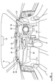
- FIG. 1 is a diagram showing a layout and the like of an information presentation system around a driver seat.
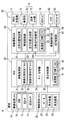
- FIG. 2 is a block diagram showing an overall image of the in-vehicle system including the HCU.
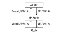
- FIG. 3 is a state transition diagram showing the transition of the operating state of the automatic driving system,
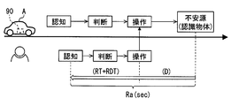
- FIG. 4 is a diagram for explaining the concept of information presentation timing and margin time,
- FIG. 5 is a flowchart showing details of the area specifying process.
- FIG. 6 is a diagram illustrating a requirement recognition range and an assumed recognition range.
- FIG. 7 is a diagram illustrating an unrecognizable area, FIG.
- FIG. 8 is a state transition diagram showing an overview of a plurality of presentation modes of the light emitting device.
- FIG. 9 is a flowchart showing details of the mode change process for switching the presentation mode.
- FIG. 10 is a flowchart showing details of the status notification processing performed in the status notification mode.
- FIG. 11 is a flowchart showing details of the front-rear behavior presentation processing performed in the vehicle behavior mode.
- FIG. 12 is a diagram illustrating an example of a lighting width setting function for setting the lighting width of the preceding light emission spot.
- FIG. 13 is a diagram illustrating an example of a period setting function for setting a repetition period of the movement or contraction of the preceding light emission spot,
- FIG. 14 is a display example in the case where the preceding light emission spot is superimposed on the notification light emission spot.
- FIG. 15 is a flowchart showing details of the left / right behavior presentation processing performed in the vehicle behavior mode.
- FIG. 16 is a diagram illustrating an example of a position setting function for setting the lighting position of the preceding light emission spot.
- FIG. 17 is a flowchart showing details of the front-rear behavior presentation processing different from FIG.
- FIG. 18 is a diagram illustrating an example of a period setting function for setting a repetition period of movement or contraction of the preceding light emission spot.
- FIG. 19 is a flowchart showing details of the left / right behavior presentation processing different from FIG.
- FIG. 20 is a flowchart showing details of the timing setting process for setting the presentation timing of the future behavior.
- FIG. 21 is a flowchart showing details of the detail level setting process for setting the detail level of the presentation information.
- FIG. 22 is a flowchart showing details of the ability limit presentation processing performed in the action induction mode.
- FIG. 23 is a diagram illustrating an example of a scene in which a plurality (four) of unrecognizable areas occur.
- FIG. 24 is a diagram showing a lighting state of the light emitting device in the scene of FIG.
- FIG. 25 is a diagram illustrating an example of a scene in which a plurality (three) of unrecognizable areas occur.
- FIG. 26 is a diagram showing a lighting state of the light emitting device in the scene of FIG.
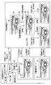
- FIG. 27 is a diagram showing a comparison of lighting modes of different preceding light emission spots for each automation level, FIG.
- FIG. 28 is a diagram comparing and comparing lighting modes of different induced light emission spots for each automation level
- FIG. 29 is a diagram showing a comparison of lighting states of different notification light emission spots for each automation level
- FIG. 30 is a flowchart showing details of the automation level presentation processing
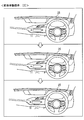
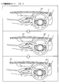
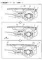
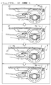
- FIG. 31 is a diagram sequentially showing information presentation by the information presentation system in use case 1.
- FIG. 32 is a diagram showing the details of the behavior presentation before and after in use case 1.
- FIG. 33 is a diagram showing the details of the behavior induction presentation in use case 1.
- FIG. 34 is a diagram showing details of the behavior induction presentation by a pattern different from FIG.
- FIG. 35 is a diagram illustrating an example of a method of fading out the induced light emission spot in accordance with the driver's confirmation action
- FIG. 36 is a diagram showing information presentation in use case 2 together with FIG.
- FIG. 37 is a diagram showing information presentation in use case 2 together with FIG.
- FIG. 38 is a diagram illustrating details of the
- the function of the presentation control apparatus is realized by an HCU (HMI (Machine Machine Interface) Control Unit) 30 illustrated in FIGS. 1 and 2.
- the HCU 30 is mounted on the vehicle A together with electronic control units such as a vehicle control ECU (Electronic Control Unit) 80 and an automatic operation ECU 50.
- the vehicle control ECU 80 and the automatic driving ECU 50 are processing devices that realize an automatic driving function for performing a driving operation on behalf of the driver, and can make the vehicle A autonomously travel in cooperation.
- the HCU 30, the automatic operation ECU 50, and the vehicle control ECU 80 are electrically connected to each other directly or indirectly, and can communicate with each other.
- the vehicle control ECU 80 is directly or indirectly electrically connected to the in-vehicle sensor group 82 and the in-vehicle actuator group 83 mounted on the vehicle A.
- the in-vehicle sensor group 82 is a plurality of sensors that detect the state of the vehicle A.
- the in-vehicle sensor group 82 includes, for example, a vehicle speed sensor, a steering angle sensor, an acceleration sensor, an accelerator position sensor, and a brake pedal sensor.
- the in-vehicle actuator group 83 executes acceleration / deceleration control and operation control of the vehicle A.
- the in-vehicle actuator group 83 includes, for example, a throttle actuator of an electronically controlled throttle, an injector, a brake actuator, and a motor generator for driving and regeneration.
- the vehicle control ECU 80 is mainly configured by a computer having a processing unit, a RAM, a memory device, an input / output interface, and the like.
- the vehicle control ECU 80 executes the vehicle control program stored in the memory device by the processing unit, thereby constructing the actuator control unit 81 as a functional block related to vehicle control.
- the actuator control unit 81 integrates the in-vehicle actuator group 83 based on at least one of the operation information based on the driving operation of the driver and the autonomous traveling information acquired from the automatic driving ECU 50 and the detection information of the in-vehicle sensor group 82. Operate and control the behavior of vehicle A.
- the automatic operation ECU 50 is directly or indirectly electrically connected to a GNSS (Global Navigation Satellite System) receiver 71, a map database 72, an autonomous sensor group 73, an automatic operation switch 76, and the like.
- the automatic driving ECU 50 constructs an automatic driving system 90 in the vehicle A together with a GNSS receiver 71, a map database 72, an autonomous sensor group 73, and the like that are configured to acquire information necessary for autonomous driving.
- GNSS Global Navigation Satellite System
- the GNSS receiver 71 can receive positioning signals transmitted from a plurality of artificial satellites.
- the GNSS receiver 71 sequentially outputs the received positioning signal to the automatic operation ECU 50 as information for specifying the current position of the vehicle A.
- the map database 72 is a storage device that stores a large number of map data. Map data includes road structure information such as curvature, slope and section length of each road, building information indicating the shape of buildings around the road, and non-temporary traffic regulation information such as speed limit and one-way traffic, etc. It is included.
- the map database 72 provides map data about the current position of the vehicle A and the traveling direction to the automatic driving ECU 50 based on a request from the automatic driving ECU 50.
- the autonomous sensor group 73 detects moving objects such as pedestrians and other vehicles, and still objects such as falling objects on the road, traffic signals, guardrails, curbs, road signs, road markings, and lane markings.
- the autonomous sensor group 73 includes, for example, a camera unit, a lidar unit, a millimeter wave radar unit, and the like. Each of the autonomous sensor groups 73 sequentially outputs object information related to the detected moving object and stationary object to the automatic driving ECU 50.
- the automatic operation switch 76 is an input device that switches the operation state of the automatic operation system 90.
- the automatic operation switch 76 is provided, for example, in the spoke portion of the steering wheel 113.
- the automatic operation switch 76 includes, for example, a SET / ON button and a Cancel / OFF button.
- the automatic driving system 90 shown in FIG. 2 can perform autonomous traveling with different automation levels.
- the automation level can be set using the definition of Society of Automotive Engineers. Specifically, at the automation levels 0 to 2, the driver performs the driving operation mainly. At this time, the automatic driving system 90 is in an off state, a standby state (automated level 0), or in a state that assists the driving operation of the driver (automated levels 1 and 2). On the other hand, at the automation levels 3 to 5, the driving operation is performed mainly by the automatic driving system 90.
- the automation level as described above may be switchable by the driver, or may be automatically changed according to the automation level permitted for the travel area.
- the automatic operation ECU 50 is mainly configured by a computer having a processing unit 61, a RAM 62, a memory device 63, and an input / output interface.
- the processing unit 61 includes at least one of a CPU (Central Processing Unit), a GPU (Graphics Processing Unit), an FPGA (Field-Programmable Gate Array), and the like.
- the processing unit 61 may be provided with a dedicated accelerator specialized in AI (Artificial Intelligence) learning and inference.
- AI Artificial Intelligence
- the automatic operation ECU 50 can execute the automatic operation program stored in the memory device 63 by the processing unit 61.
- the automatic driving program includes a program for autonomously driving the vehicle A, a program for controlling driving changes between the driver and the automatic driving system 90, and the like.
- a self-vehicle position specifying unit 51, an environment recognizing unit 52, a travel plan generating unit 53, an autonomous travel control unit 54, and the like are constructed in the automatic driving ECU 50.
- the own vehicle position specifying unit 51 specifies the current position of the vehicle A based on the positioning signal received by the GNSS receiver 71.
- the own vehicle position specifying unit 51 corrects the detailed current position of the vehicle A by comparing the image of the front area acquired from the camera unit of the autonomous sensor group 73 with the detailed map data acquired from the map database 72.
- the environment recognizing unit 52 combines the position information specified by the vehicle position specifying unit 51, the map data acquired from the map database 72, the object information acquired from the autonomous sensor group 73, and the like. Recognize the driving environment.
- the environment recognizing unit 52 acquires a recognition result obtained by recognizing the shape and moving state of objects around the vehicle A based on the integration result of each object information, particularly within the detection range of each autonomous sensor.
- the environment recognition unit 52 implements the function of the periphery monitoring device 70 together with the autonomous sensor group 73.
- the environment recognition unit 52 generates a virtual space in which the actually recognized traveling environment is reproduced in three dimensions by combining the recognition result around the vehicle A, the position information, and the map data.
- a functional part including the environment recognition unit 52 and the autonomous sensor group 73 is referred to as a periphery monitoring device 70.
- the travel plan generation unit 53 generates a travel plan for causing the vehicle A to autonomously travel by the automatic driving system 90 based on the travel environment recognized by the environment recognition unit 52.
- a long-term travel plan and a short-term travel plan are generated.
- a route for directing the vehicle A to the destination set by the driver is defined.
- a planned travel route for realizing travel according to the long-term travel plan is defined using the virtual space generated by the environment recognition unit 52. Specifically, execution of lane following, steering for lane change and right / left turn, acceleration / deceleration for speed adjustment and temporary stop, and the like is determined based on a short-term travel plan.
- the autonomous traveling control unit 54 generates autonomous traveling information instructing acceleration / deceleration and steering based on the planned traveling route formulated by the traveling plan generating unit 53 in the automatic operation mode.
- the autonomous traveling control unit 54 sequentially outputs the generated autonomous traveling information to the vehicle control ECU 80.
- the autonomous traveling control unit 54 cooperates with the actuator control unit 81 to cause the vehicle A to autonomously travel along the planned traveling route.
- the HCU 30 is further connected to the occupant monitoring system 10, the information presentation system 20, and the like.
- the occupant monitoring system 10 is a system that mainly monitors the state of a driver sitting in the driver's seat 110 (see FIG. 1).
- the occupant monitoring system 10 includes a DSM (Driver Status Monitor) 11, a foot sensor 12 and a grip sensor 13.
- DSM Driver Status Monitor
- the DSM 11 includes a near-infrared light source and a near-infrared camera and a control unit for controlling them.
- the DSM 11 is arranged, for example, on the upper surface of the instrument panel in a posture with the near-infrared camera facing the driver's seat side.
- the DSM 11 photographs the upper body of the driver irradiated with near infrared light from a near infrared light source with a near infrared camera in order to monitor the driver's condition.
- the DSM 11 sequentially outputs the captured image as detection information to the HCU 30.
- the foot sensor 12 is an active object detection sensor that detects an object by light irradiation.
- the detection range of the foot sensor 12 is set so as to particularly include an accelerator pedal and a brake pedal.
- the foot sensor 12 detects the position of the driver's foot among the floor, the accelerator pedal, the brake pedal, and the like, and sequentially outputs detection information to the HCU 30.
- the grip sensor 13 is provided on the rim portion of the steering wheel 113 (see FIG. 1), and detects the grip of the steering wheel 113 by the driver.
- the grip sensor 13 sequentially outputs detection information indicating whether or not the driver is gripping the steering wheel 113 toward the HCU 30.
- the information presentation system 20 is a system that presents information related to the vehicle A to each occupant of the vehicle A including the driver.
- the information presentation system 20 includes presentation devices such as a speaker 21, a display device 22, and a light emitting device 23.
- the speaker 21 can reproduce, for example, a warning sound and a voice message.
- the display device 22 is mainly composed of a liquid crystal display, for example.
- the display device 22 is installed on the instrument panel with the display surface facing the driver's seat 110.
- the display device 22 can display various images and characters on the display screen.
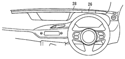
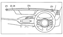
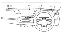
- the light-emitting device 23 is a presentation device that presents information to the occupant according to the light-emission mode of the light-emitting spot 25 that displays light in the linear stretch region 24.
- the linear extending region 24 extends linearly along the width direction WD of the vehicle A.
- a large number of light emitting elements (for example, LEDs) arranged along the width direction WD are provided in the linear extending region 24.
- the light emitting device 23 can change the number, size, position, moving direction, moving speed, light emitting color (hue, saturation, brightness), light emission luminance, and the like of the light emitting spots 25 displayed in the linear extending region 24.
- a dark dot range indicates a light-off region
- a white or very thin dot range indicates a light-emitting region where the light-emitting spot 25 is formed.
- the HCU 30 is an electronic control unit that integrally controls information presentation to the driver using the information presentation system 20.
- the HCU 30 is mainly configured by a computer having a processing unit 41, a RAM 42, a memory device 43, an input / output interface, and the like.
- the processing unit 41 includes at least one of a CPU, GPU, FPGA, and the like.
- the processing unit 41 may be provided with a dedicated accelerator specialized for AI learning and inference.
- the HCU 30 can execute the presentation control program stored in the memory device 43 by the processing unit 41.
- the presentation control program includes a program related to driver state estimation, a program related to operation control of the information presentation system 20, and the like. Based on the presentation control program, an information acquisition unit 31, a mode switching unit 34, a presentation control unit 35, and the like are constructed in the HCU 30.
- the information acquisition unit 31 acquires various information necessary for presentation using the information presentation system 20 from the occupant monitoring system 10, the automatic driving ECU 50, the vehicle control ECU 80, and the like. Specifically, the information acquisition unit 31 relates to status information of the automatic driving system 90, vehicle state information indicating the driving state of the vehicle A, driver detection information by the occupant monitoring system 10, and driving environment recognition by the periphery monitoring device 70. Acquired recognition information and the like. The information acquisition part 31 may acquire each information required for information presentation by communication, or may acquire each of these information by the process which processes the information acquired by communication.
- the status information includes, for example, information indicating the operating state of the automatic driving system 90 and information indicating the automation level of autonomous driving.
- the vehicle state information includes the speed information of the vehicle A measured using the vehicle speed sensor, the steering information of the vehicle A measured using the steering angle sensor, the information indicating the current position of the vehicle A, and the state of the surrounding traveling environment The environmental information etc. which show are included.
- the detection information is a detection result output from the DSM 11, the foot sensor 12, and the grip sensor 13.
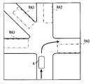
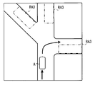
- the recognition information includes relative position information of the object recognized by the periphery monitoring device 70, a short-term travel plan created using the recognition result, and direction information indicating the direction of the unrecognizable area RA3 (see FIG. 7). It is out.
- the information acquisition unit 31 includes an occupant state determination block 32 and a recognition state determination block 33 as sub function blocks. As described above, the occupant state determination block 32 and the recognition state determination block 33 use the information provided from the occupant monitoring system 10, the automatic driving ECU 50, and the vehicle control ECU 80 to generate information necessary for information presentation. It is.
- the occupant state determination block 32 determines the state of the driver using the detection information from the occupant monitoring system 10. Specifically, the occupant state determination block 32 relates to the driving posture, such as the driver's viewing direction, whether the steering wheel 113 and other operating systems are gripped, and whether the foot is positioned at the position where the brake pedal is stepped on. Make the decision. In addition, the occupant state determination block 32 calculates the driver's anxiety using a predetermined arithmetic expression based on the driver's facial expression, the number of blinks, hand and leg movements, and the driving posture described above. To do. For such calculation of the degree of anxiety, information such as the heart rate of the driver may be further used.
- the heart rate is measured by, for example, a wearable device worn by the driver, and transmitted to the HCU 30 by wireless communication or the like.
- Information indicating the driving posture and the degree of anxiety may be generated by the occupant monitoring system 10 and provided to the information acquisition unit 31 sequentially. In such a form, the occupant state determination block 32 can be omitted.
- the recognition state determination block 33 determines the traveling environment of the vehicle A using the recognition result by the periphery monitoring device 70. Specifically, the recognition state determination block 33 selects a risk target that is a target of alerting the occupant from the objects recognized by the periphery monitoring device 70. In addition, the recognition state determination block 33 grasps the presence of the unrecognizable area RA3 (see FIG. 6) that cannot be recognized by the periphery monitoring device 70. Note that the calculation for selecting the risk target and the calculation for grasping the unrecognizable area RA3 may be performed by the environment recognition unit 52. If both of these calculation results are provided to the information acquisition unit 31, the recognition state determination block 33 can be omitted.
- the risk target is an object whose margin time Ra for the vehicle A is negative among the objects indicated by the relative position information.
- the allowance time Ra is the minimum time necessary for responding to the object by recognizing, judging and operating the object.
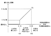
- the allowance time Ra is the sum of the driver's reaction time RT and the driver's reaction delay time RDT and the time D required to respond by a braking operation or a steering operation (see FIG. 4).
- the recognition state determination block 33 calculates the margin time Ra of each recognition object based on the relative position information, and selects a recognition object having a negative value (minus) as the risk time Ra.
- the unrecognizable area RA3 is a range that becomes a capability limit of the periphery monitoring device 70, and is calculated from a difference between a sensing range necessary for autonomous traveling and a current sensing possible range.
- the recognition state determination block 33 includes a request recognition range RA1 (see FIG. 6) required by the automatic driving system 90 and an assumed recognition range RA2 (see FIG. 6) where actual recognition by the periphery monitoring device 70 is assumed.
- the unrecognizable area RA3 is set using the difference from ().
- the recognition state determination block 33 specifies the occurrence of the unrecognizable area RA3 and the direction of the unrecognizable area RA3 as viewed from the driver by area specifying processing (see FIG. 5). At least a part of the area specifying process may be executed by the environment recognition unit 52, for example.
- the area specifying process is started based on switching of the vehicle power source to the on state, and is continued until the vehicle power source is turned off.
- an assumed speed Vs (m / s) of another vehicle traveling around is acquired, and the process proceeds to S103.
- the assumed speed Vs is set to, for example, a value obtained by adding a specific value (for example, 20 km / h ⁇ 5.6 m / s) to the speed limit, or a value that can include 95% of vehicles in a normal traffic volume.
- the assumed speed Vs can be set using accumulated normal speed data. For example, 2 ⁇ ( ⁇ : standard deviation of speed) is added to the average moving speed. Set to a value.
- S103 the behavior of the host vehicle (vehicle A) after a few seconds based on the travel plan is acquired, and the process proceeds to S104.
- S104 the estimated required time T (s) related to the own vehicle behavior acquired in S103 is acquired, and the process proceeds to S105. For example, when a right turn is planned as the vehicle behavior, an estimated required time T of 6 to 7 seconds is acquired.
- the required recognition range RA1 is calculated mainly using map data. Specifically, the product of the estimated speed Vs acquired in S102 and the estimated required time T acquired in S104 with the radius of the product of the vehicle A as a center. (See FIG. 6).
- the weather information, the time zone information, the prospect information, and the like for considering the quality of the surrounding visual field are acquired as the environmental information around the vehicle A, and the process proceeds to S107.
- the line-of-sight information is information indicating the presence / absence and shape of a roadside shielding object based on map data or the like.
- the assumed recognition range RA2 is calculated using the environment information acquired in S106, and the process proceeds to S108.
- the assumed recognition range RA2 is acquired by a process of narrowing the maximum detection range of the autonomous sensor group 73 (see FIG. 2) using the environment information acquired in S106.
- the range that is the blind spot of the shielding object BO is out of the assumed recognition range RA2 (see FIG. 7).
- the unrecognizable area RA3 is fitted to the road shape shown in the map data (see FIG. 7), the unrecognizable area RA3 is set in the range where the risk target can exist, and the process proceeds to S110.
- the unrecognizable area RA3 is set on the road in a range where it becomes a blind spot from the own vehicle due to the shield BO such as a bag.
- the direction of the unrecognizable area RA3 viewed from the driver is set based on the relative position of the at least one unrecognizable area RA3 (see FIG. 7) extracted in S109.
- a plurality of directions are set (see also FIG. 23, FIG. 25, etc.).
- the information acquisition unit 31 can sequentially acquire the direction information of the unrecognizable area RA3.
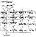
- the mode switching unit 34 switches information presentation using the information presentation system 20 among a plurality of presentation modes according to the state of the vehicle A.
- the HCU 30 is preset with four presentation modes: a state notification mode, a preventive safety mode, a vehicle behavior mode, and an action induction mode.
- the state of the vehicle A that triggers the switching of the presentation mode includes the state of the vehicle A itself, the state of the vehicle A caused by the traveling environment such as whether or not a risk target is detected, and whether or not a specific operation is input.
- the state of the vehicle A caused by the driver is also included.
- the mode switching unit 34 sets the presentation mode to the vehicle behavior mode during normal autonomous driving.
- the mode switching unit 34 switches the presentation mode from the vehicle behavior mode to the preventive safety mode when a risk target occurs during autonomous traveling (Ra ⁇ 0).
- the mode switching unit 34 switches the presentation mode from the preventive safety mode to the vehicle behavior mode.
- the mode switching unit 34 switches the presentation mode from the vehicle behavior mode to the behavior induction mode.
- the mode switching unit 34 changes the presentation mode to the state notification mode. At this time, the automatic driving system 90 is in a standby state.
- the mode switching unit 34 switches from the state notification mode to the vehicle behavior mode. Transition the presentation mode.
- the mode switching unit 34 changes the presentation mode from the state notification mode to the preventive safety mode.
- the operation (start trigger) for resuming the autonomous running includes a pressing operation of the SET / ON button, a pedal operation of lightly depressing the accelerator pedal, and the like.
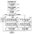
- the mode switching unit 34 transitions each presentation mode as described above by executing the mode change process.
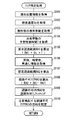
- the mode change process is started based on switching of the vehicle power source to the on state, and is continued until the vehicle power source is turned off. Details of the mode change process will be described below with reference to FIGS. 2 and 8 based on FIG.
- S121 information indicating the operating state (hereinafter, “AD state”) of the automatic driving system 90 is acquired, and the process proceeds to S122.
- AD state the operating state of the automatic driving system 90
- S122 the selection result of the risk target based on the margin time Ra (see FIG. 4) is determined. If there is a risk target whose margin time Ra is negative, the process proceeds to S123.
- S123 the presentation mode is set to the preventive safety mode, and the process returns to S121.
- the process proceeds to S124.
- S124 the AD state acquired in S121 is determined. If it is determined in S124 that the AD state is an off state or a standby state, the process proceeds to S125.
- S125 the presentation mode is set to the state notification mode, and the process returns to S121.
- the process proceeds to S126.
- S126 the presence / absence of the unrecognizable area RA3 (see FIG. 7) extracted by the recognition state determination block 33 or the like is determined. If it is determined in S126 that there is an unrecognizable area RA3, the process proceeds to S127. In S127, the presentation mode is set to the action induction mode, and the process returns to S121. On the other hand, when it is determined in S126 that there is no unrecognizable area RA3, the process proceeds to S128. In S128, the presentation mode is set to the vehicle behavior mode, and the process returns to S121.
- the presentation control unit 35 shown in FIG. 2 controls information presentation by the information presentation system 20 using the recognition information acquired by the information acquisition unit 31 and the like.
- the presentation control unit 35 has a playback control function for notification sounds and voice messages from the speaker 21, a display control function for the display device 22, and a light emission control function for the light emitting device 23.
- the light emission control function of the light emitting device 23 the light emission mode of the light emission spot 25 is changed according to the switching of the presentation mode by the mode switching unit 34, and is appropriately changed based on the latest recognition information or the like in each presentation mode.
- the presentation control unit 35 adjusts the light emission luminance of the light emission spot 25 according to the recognition reliability of the periphery monitoring device 70. Specifically, when the reliability of the driving environment recognition is reduced due to backlight, rain, dirt, or the like, the presentation control unit 35 does not reduce the reliability of the light emission luminance of the light emission spot 25. Set lower than the state. Further, the presentation control unit 35 causes the light emitting device 23 to emit light in different emission colors that are defined in advance for each presentation mode in each presentation mode set by the mode switching unit 34. Hereinafter, details of the light emission control in each presentation mode will be described in order with reference to FIGS. 2 and 8.
- the state notification mode is a presentation mode indicating the state of the automatic driving system 90, and specifically notifies the driver that the automatic driving system 90 is in an off state or a standby state.
- the state notification mode clearly indicates to the driver that the driver's operation (permission) for switching the automatic driving system 90 to the on state is necessary.
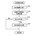
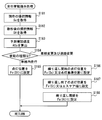
- the presentation control unit 35 performs the state notification process shown in FIG. 10 in the state notification mode.
- the state notification process is started based on switching from the action induction mode to the state notification mode.
- the light emitting device 23 is turned off, and the process proceeds to S132.
- the occupant is notified of the standby state of the automatic driving system 90.
- the start permission information is acquired, and the process proceeds to S133.
- the start permission information is information indicating an input of a start trigger for resuming autonomous travel, and is information output from the automatic driving ECU 50.
- it waits for acquisition of start permission information. If the start permission information is acquired in S133, the process proceeds to S134. In S134, switching to the light emission control of the vehicle behavior mode or the preventive safety mode is performed according to the presence or absence of the risk target, and the state notification process is terminated.
- the preventive safety mode is a presentation mode that alerts the presence of risk objects around the vehicle A.
- the presentation control unit 35 presents the relative position of the risk target around the vehicle A grasped by the recognition state determination block 33 using a light emission spot (hereinafter, “notification light emission spot 28”).
- notification light emission spot 28 For example, when there is an object that requires abrupt avoidance, the direction is indicated to the driver.
- the lighting position of the notification light emitting spot 28 is set to an intersection position where a virtual line connecting the driver's eye point and the risk target and the linear extension region 24 intersect in a top view. As described above, the notification light emission spot 28 is lit in the direction of the risk target as viewed from the driver.
- the presentation control unit 35 can guide the driver's visual recognition direction by moving the notification light emitting spot 28 in either the left or right direction where the risk target exists, for example.
- the driver can respond when the avoidance support by the automatic driving system 90 is insufficient.
- oversight of risk targets by the driver can be reduced when the automatic driving system 90 restarts.
- the light emission color of the notification light emission spot 28 is, for example, orange (amber).
- the notification light emission spot 28 can cause the occupant to foresee the occurrence of a sudden behavior than usual by lighting in a light emission color different from that of the light emission spot 25 in other presentation modes.
- the occupant of the vehicle A can be prepared in advance for a sudden change in vehicle behavior by the automatic driving system 90.
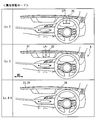
- the vehicle behavior mode is a presentation mode in which the future behavior of the autonomous traveling planned by the travel plan generation unit 53 is presented in advance by a light emitting spot (hereinafter, “preceding light emitting spot 26”).
- preceding light emitting spot 26 a light emitting spot
- the occupant of the vehicle A can acquire a clue to know the capability limit of the periphery monitoring device 70.
- the occupant of the vehicle A determines the future behavior of the object around the vehicle A. It becomes possible to foresee that the contents are missed.
- the occupant of the vehicle A can notice the misrecognition or unrecognition of the periphery monitoring device 70 using the future behavior as a clue before appearing in the vehicle behavior. Therefore, in the vehicle behavior mode, the future behavior functions as information indicating an unknown capability limit.
- the light emission color of the preceding light emission spot 26 in the vehicle behavior mode is a light emission color different from the preventive safety mode and the action induction mode, for example, green.
- the presentation control unit 35 lights the preceding light-emitting spot 26 at the lighting reference position LPr (see FIG. 8).
- the lighting reference position LPr is defined as the front position of the driver's seat 110 (see FIG. 1).
- the presentation control unit 35 performs front-rear behavior presentation, left-right behavior presentation, and the like when a behavior change from straight ahead is scheduled in the travel plan.
- the content of the animation displayed in each behavior presentation can be changed according to the planned behavior change amount or the type of behavior change.
- the presentation control unit 35 can adjust the timing and level of detail of information presentation according to the driver's state.
- the presentation control unit 35 causes the light emitting device 23 to present the front-rear behavior when the deceleration behavior is scheduled in the travel plan.
- the animation is changed according to the amount of behavior change.
- the preceding light-emitting spot 26 is lit at the lighting reference position LPr, and notifies the deceleration of the vehicle A felt by the occupant by expansion and contraction in the width direction WD.
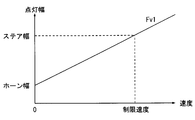
- the presentation control unit 35 changes the lighting width and period in the telescopic display of the preceding light emitting spot 26 according to the amount of change in the deceleration behavior planned in the travel plan.
- the presentation control unit 35 sets a lighting width setting function Fv1 (see FIG.
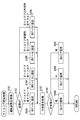
- S141 of the front / rear behavior presentation process shown in FIG. 11 the current speed information Vc is acquired, and the process proceeds to S142.
- S142 speed information Vt after a few seconds specified in the travel plan is acquired, and the process proceeds to S143.
- S143 the predicted acceleration Atd in the front-rear direction acting on the vehicle A is calculated based on the speed difference indicated by the speed information Vc and Vt acquired in S141 and S142, and the process proceeds to S144.
- the predicted acceleration Atd calculated in S143 is compared with two threshold values th1 and th2 defined in advance.
- the threshold th1 is an acceleration serving as a boundary whether or not a person feels, and is about 0.1 G, for example.
- the threshold th2 is an acceleration serving as a boundary whether or not a person becomes anxious, and is about 0.2 G, for example. If it is determined in S144 that the predicted acceleration Atd is less than the threshold th1, the process proceeds to S145.
- the lighting width of the preceding light emitting spot 26 is set using the lighting width setting function Fv1 (see FIG. 12), and the process returns to S141.
- the lighting width is defined according to the vehicle speed, and is set wider as the future speed indicated by the speed information Vt becomes higher.
- the lighting width setting function Fv1 is defined such that the lighting width corresponding to the stop (speed zero) is the horn width, and the lighting width corresponding to the speed limit of the traveling road is the steering width.
- the horn width is approximately the same as the lateral width of the center pad of the steering wheel 113.
- the steer width is approximately the same as the outer diameter of the steering wheel 113.
- the process proceeds to S146.
- the lighting width setting function Fv1 (see FIG. 12) is used to set the lighting width at the start of repetition, and the process proceeds to S147.
- the lighting width at the end of repetition is set using the lighting width setting function Fv1, and the process proceeds to S148.
- the lighting width at the start of repetition may be set to the steer width.
- the lighting width at the end of repetition may be set to the horn width.
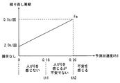
- the cycle setting function Fa (see FIG. 13) is used to set a repetition cycle of the animation for expanding and contracting the preceding light emitting spot 26, and the process returns to S141.
- the repetition period is defined according to the longitudinal acceleration, and is set shorter as the predicted acceleration Atd increases.
- the repetition period is set, for example, in a range close to a person's heart rate, and specifically, adjusted in a range of 0.5 to 2.0 (seconds / time).
- the animation expression of the preceding light spot 26 becomes larger as the vehicle speed and acceleration are larger and the uneasiness of the passenger is more likely to increase. Therefore, the occupant can intuitively understand the future movement of the vehicle A and the steepness of the behavior change. In addition, when the vehicle speed and acceleration are small and anxiety of the occupant is suppressed, the animation expression of the preceding light emission spot 26 becomes small. As a result, the occupant's troublesomeness can be reduced.
- the presentation mode is switched from the vehicle behavior mode to the preventive safety mode.
- the presentation control unit 35 causes the light-emitting device 23 to display the preceding light-emitting spot 26 on the notification light-emitting spot 28 (see FIG. 14). From the viewpoint of the driver, the preceding light emission spot 26 is superposed on the notification light emission spot 28. The size (horizontal width) of the notification light emission spot 28 is larger than the size of the preceding light emission spot 26. The preceding light spot 26 is turned off after showing the future behavior of the vehicle A.
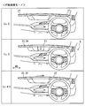
- the presentation control unit 35 causes the light emitting device 23 to present the left-right behavior when a behavior accompanied by left-right movement (hereinafter, “left-right behavior”) is scheduled in the travel plan.
- the animation is changed according to the amount of behavior change.
- the preceding light emitting spot 26 gives a notice of the lateral movement of the vehicle A felt by the occupant by displaying repeatedly moving left or right. For example, when a left turn of the vehicle A, a lane change to the left lane, a merge in the left direction, and the like are scheduled, the preceding light emitting spot 26 repeats a movement flowing in the left direction. Similarly, when a right turn of the vehicle A, a lane change to the right lane, a merge in the right direction, and the like are scheduled, the preceding light emission spot 26 repeats a movement flowing in the right direction.
- the presentation control part 35 changes the movement width and period in the horizontal movement display of the prior
- the presentation control unit 35 sets a position setting function Fv2 (see FIG. 16) for defining the lighting mode of the preceding light emitting spot 26 and a cycle setting function Fa (see FIG. 12) for defining the cycle of movement.
- Fv2 see FIG. 16
- a cycle setting function Fa for defining the cycle of movement.
- S151 of the left / right behavior presentation process shown in FIG. 15 the current steering information Sc is acquired, and the process proceeds to S152.
- S152 the steering information St after a few seconds specified in the travel plan is acquired, and the process proceeds to S153.
- S153 the predicted lateral acceleration Ats in the left-right direction acting on the vehicle A is calculated based on the steering angle difference indicated by the steering information Sc and St acquired in S151 and S152, and the process proceeds to S154.
- the predicted lateral acceleration Ats calculated in S153 is compared with two threshold values th1 and th2 defined in advance.
- the threshold values th1 and th2 may be the same as the values used in the front / rear behavior presentation process. If it is determined in S154 that the predicted lateral acceleration Ats is less than the threshold th1, the process proceeds to S155.
- the lighting position of the preceding light-emitting spot 26 is set using the position setting function Fv2 (see FIG. 16), and the process returns to S151.
- the lighting position is defined according to the steering angle, and is set at a position away from the lighting reference position LPr in either the left or right steering direction as the future steering angle indicated by the steering information St increases.
- the steering angle is 90 ° or more
- the preceding light emitting spot 26 apparently coincides with the left end or the right end of the steering wheel 113 at a position ( ⁇ steer width) separated from the lighting reference position LPr by the radius of the steering wheel 113. Is displayed.
- the process proceeds to S156.
- the position setting function Fv2 (see FIG. 16) is used to set the lighting position for repeated start, and the process proceeds to S157.
- the position setting function Fv2 is used to set the lighting position at the end of repetition, and the process proceeds to S158.
- the lighting position at the start of repetition may be set to the lighting reference position LPr. Further, the lighting position at the end of repetition may be set to a position of ⁇ steer width.
- the cycle setting function Fa (see FIG. 13) is used to set an animation repetition period for moving the preceding light-emitting spot 26, and the process returns to S151.
- the repetition cycle is defined according to the lateral acceleration, and is set shorter as the predicted lateral acceleration Ats increases.
- the repetition cycle of the left / right behavior presentation is adjusted in the range of 0.5 to 2.0 (seconds / times), similarly to the front / rear behavior presentation.
- the animation expression of the preceding light-emitting spot 26 becomes larger as the steering angle and the change in the steering angle are larger and the passenger's anxiety is more likely to increase. Therefore, the occupant can intuitively understand the future movement of the vehicle A and the steepness of the behavior change. In addition, when the steering angle and the steering angle change are small and anxiety of the occupant is suppressed, the animation expression of the preceding light spot 26 becomes small. As a result, the occupant's troublesomeness can be reduced.
- the presentation control unit 35 changes the animation mode using the preceding light emission spot 26 as another display pattern for presenting the front-rear behavior according to the type of deceleration behavior planned in the travel plan.
- the presentation control unit 35 displays an animation when the signal is scheduled to pass through and an animation when the signal is scheduled to stop in a different manner.
- the presentation control unit 35 defines the lighting width and period in the expansion / contraction display of the preceding light emitting spot 26 based on the lighting width setting function Fv1 (see FIG. 12) and the period setting function Fa (see FIG. 18). To do.
- Fv1 see FIG. 12
- Fa period setting function
- the speed information Vc, Vt after the current and several seconds later and the predicted acceleration Atd in the front-rear direction are obtained by substantially the same process as S141-S143 (see FIG. 11). And the process proceeds to S164.
- S164 the type of future behavior scheduled in the travel plan is determined. If it is determined in S164 that the vehicle stops at a signal, specifically, a temporary stop, a red light stop, a stop for waiting for a right turn, a stop following the preceding vehicle, etc., the process proceeds to S166. .
- the lighting width at the start of repetition, the lighting width at the end of repetition, and the repetition period are set to the lighting width setting function Fv1 (see FIG. 12) and the period setting by substantially the same processing as S146 to S148 (see FIG. 11). It sets using the function Fa (refer FIG. 18).
- the animation for contracting the preceding light emission spot 26 toward the lighting reference position LPr is repeatedly displayed.
- the process proceeds to S169.
- the lighting width at the start of repetition is set to the horn width, and the process proceeds to S170.
- a lighting width at the end of repetition is set using a lighting width setting function Fv1 (see FIG. 12), and the process proceeds to S171.
- the lighting width at the end of repetition set in S170 may be a steer width.
- the repetition cycle of expansion and contraction of the preceding light-emitting spot 26 is set using the cycle setting function Fa (see FIG. 18). As described above, the animation for expanding the preceding light emitting spot 26 to the outside is repeatedly displayed in the signal passing schedule presentation.
- the process proceeds to S165.
- the lighting width of the preceding light-emitting spot 26 is set by substantially the same processing as S145 (see FIG. 11), and the process returns to S161. In this case, the preceding light emission spot 26 having a lighting width corresponding to the speed after deceleration is displayed at the lighting reference position LPr.
- the presentation control unit 35 changes the mode of animation using the preceding light-emitting spot 26 as another display pattern for presenting the left-right behavior according to the type of left-right behavior planned in the travel plan. Even in the presentation of left and right behavior, if the classification of future behavior is presented in detail, the passenger can easily understand the future behavior. As an example, the presentation control unit 35 displays a left-right behavior animation for maintaining traveling in a lane and a left-right movement animation across the lane in different modes. Even in such another pattern, the presentation control unit 35 defines the movement width and period in the lateral movement display of the preceding light emitting spot 26 based on the position setting function Fv2 (see FIG. 16) and the period setting function Fa (see FIG. 18). To do. The details of another left / right behavior presentation process for changing the mode of animation according to the type of planned left / right behavior will be described below.
- the process proceeds to S186.
- the position setting function Fv2 (see FIG. 16) is used to set the lighting position for repeated start, and the process proceeds to S187.
- the position setting function Fv2 is used to set the lighting position at the end of repetition, and the process proceeds to S188.
- S188 based on the predicted lateral acceleration Ats calculated in S183, a repetition period for moving the preceding light emitting spot 26 is set using the period setting function Fa (see FIG.
- the lighting position at the start of repetition may be set to the lighting reference position LPr. Further, the lighting position at the end of repetition may be set to ⁇ steer width.
- the presentation control unit 35 can change the timing of the advance presentation according to the driver's state.
- the presentation control unit 35 uses the calculation result of the margin time Ra (see FIG. 4) in the recognition state determination block 33 to adjust the timing of the previous presentation to a time when the occupant does not feel uneasy.
- the presentation control unit 35 presents the recognition and determination in the automatic driving system 90 at the same timing as the driver's recognition and determination (see FIG. 4).
- the advance presentation timing is set to a time when the margin time Ra is about 0 to 2 seconds, and is adjusted according to the driving posture and the anxiety level of the driver. According to such setting, even when the recognition and determination in the automatic driving system 90 are wrong, the driver can respond without anxiety.
- the details of the timing setting process for setting the timing of prior presentation will be described below.
- S191 of the timing setting process shown in FIG. 20 information related to the driving posture determined in the occupant state determination block 32 is acquired, and the process proceeds to S192.
- S192 the current driving posture of the driver is diagnosed based on the information acquired in S191. If it is determined in S192 that the driver's hand is holding the steering wheel 113 and the driver's foot is stepping on the brake pedal, the process proceeds to S193. In S193, since the driver is in the correct driving posture, the driver's reaction delay time RDT (see FIG. 4) is set to zero, and the process proceeds to S197.
- the process proceeds to S194.
- the driver's reaction delay time RDT is set to 0.5 seconds, and the process proceeds to S197.
- the process proceeds to S195.
- the driver's reaction delay time RDT is set to 1.0 second, and the process proceeds to S197.
- the process proceeds to S196.
- the driver's reaction delay time RDT is set to 2.0 seconds, and the process proceeds to S197.
- S197 the driver's anxiety degree calculated in the occupant state determination block 32 is acquired, and the process proceeds to S198.
- the degree of anxiety acquired in S197 is determined. If it is determined in S198 that the degree of anxiety is low, the process proceeds to S199.
- S199 the time when the margin time Ra becomes zero is set as the presentation timing.
- the process proceeds to S200, and the time when the margin time Ra is 1.0 second is set as the presentation timing. If it is determined in S198 that the degree of anxiety is high, the process proceeds to S201, and the time when the margin time Ra is 2.0 seconds is set as the presentation timing. As a result of the above processing, the higher the degree of anxiety, the earlier the timing of prior presentation with respect to the arrival time at the source of anxiety.
- the presentation control unit 35 can adjust the level of detail of information presentation according to the driver's state (anxiety level).
- the presentation control unit 35 causes the information presentation system 20 to present more detailed information when the driver's anxiety level is higher and higher.
- the presentation control unit 35 stops the summary presentation when the driver's sense of security is high or higher. According to the adjustment of the information granularity according to the degree of anxiety, it is possible to ensure both a sense of security and a reduction in bothersomeness.
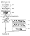
- the details of the detail level setting process for setting the detail level of information presentation will be described below.
- the driver's anxiety level calculated in the occupant state determination block 32 is acquired, and the process proceeds to S212.
- S212 the degree of anxiety acquired in S211 is determined. If it is determined in S212 that the degree of anxiety is low, the process proceeds to S213.
- the display device used for information presentation in the information presentation system 20 is set to the display device 22 and the light emitting device 23.
- the information presentation in this case is a content that shows an outline of the future behavior, and is intended to realize monitoring by the driver and understanding of the instantaneous information in parallel with the peripheral monitoring.
- the process proceeds to S214.
- S214 in addition to the display device 22 and the light emitting device 23, the speaker 21 is set as a presentation device to be used. In this case, the passenger 21 is notified of the content of the future behavior by the speaker 21. Furthermore, if it is determined in S212 that the degree of anxiety is high, the process proceeds to S215. In S215, as in S214, the light emitting device 23, the display device 22, and the speaker 21 are set to be used. In this case, in addition to the contents of the future behavior, the reason for the behavior change is notified to the occupant by at least one of display and sound. According to such information presentation, the driver can confirm the details of the behavior change as necessary.
- the behavior induction mode is a presentation mode that notifies the occurrence of the unrecognizable area RA3 (see FIG. 7) and prompts the driver to perform confirmation action or driving change of the unrecognizable area RA3.
- the unrecognizable area RA3 is an area indicating the capability limit of the periphery monitoring device 70, and is an area where the automatic driving system 90 cannot grasp the situation.
- the unknown ability limit is presented indirectly, whereas in the behavior induction mode, the known ability limit is presented directly. Since the capability limit of the peripheral monitoring device 70 is known in advance and it becomes easy to understand which direction should be confirmed, the driver can cope with the capability limit with a margin.
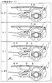
- the presentation control unit 35 presents the presence of the unrecognizable area RA3 (see FIG. 7) grasped by the recognition state determination block 33 using a light emission spot (hereinafter referred to as “guided light emission spot 27”, see FIG. 8).
- the light emission color of the induced light emission spot 27 in the behavior induction mode is a light emission color different from that in the preventive safety mode in order to prevent confusion with the case where there is a risk target, for example, yellow.
- the induced light spot 27 indicates the direction of the unrecognizable area RA3 as viewed from the driver. Details of the capability limit presentation processing for controlling the presentation of the unrecognizable area RA3 will be described below with reference to FIG. 22 and FIGS. 23 to 26 together with FIG.
- the direction information (see S110 in FIG. 5) of the unrecognizable area RA3 grasped by the recognition state determination block 33 is acquired, and the process proceeds to S302.
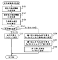
- the number of directions in the current unrecognizable area RA3 is determined from the direction information acquired in S301.
- the lighting pattern is changed according to the number of occurrences of the capacity limit. If the number of directions is zero in S302, that is, if there is no unrecognizable area RA3, the process returns to S301.
- the process proceeds to S303.
- the lighting position of the induced light emission spot 27 (see FIG. 8) is set in the direction of the unrecognizable area RA3, and the process proceeds to S304.
- S304 between the lighting positions set in S304, it is set as a light-off state, and the process proceeds to S307.
- S302 when it is determined that the number of directions of the unrecognizable area RA3 is three or more (see FIGS. 23 and 25), the process proceeds to S305. In this case, all the two directions indicating the outermost unrecognizable area RA3 are turned on. In S305, both end positions of the light emission range 27a are defined. Specifically, in S305, among the directions of the plurality of unrecognizable areas RA3, a position 27r that is the right end as viewed from the driver and a position 27l that is the left end are set, and the process proceeds to S306 (see FIGS. 24 and 26). In S306, the lighting state is set between the two lighting positions set in S305, and the process proceeds to S307. According to the band-like light emission in the light emission range 27a, it is possible to prevent the occupant from being confused due to the lighting of the many induced light emission spots 27.
- S307 information indicating the viewing direction of the driver specified in the occupant state determination block 32 (hereinafter, “viewing direction information”) is acquired, and the process proceeds to S308.
- viewing direction information information indicating the viewing direction of the driver specified in the occupant state determination block 32
- the guide light emission spot 27 is moved from the lighting reference position LPr in front of the driver's seat 110 to the lighting position set in S303 or S305, and the process proceeds to S310.
- the guided light emission spot 27 is repeatedly moved for a specific time or a specific number of times, and the process proceeds to S313.
- the process proceeds to S311.
- S311 in the top view, the guide light emission spot 27 is moved from the intersection position where the imaginary line defining the line-of-sight direction and the linear extension region 24 (see FIG. 24) intersect to the lighting position set in S303 or S305. Move to S312.
- S312 after repeating the movement of the induced light emission spot 27 for a specific time or a specific number of times, the process proceeds to S313.
- Each presentation mode described so far is based on the premise of automatic operation at automation level 2.
- the presentation control unit 35 illuminates the light emission mode of the light emission spot 25 in each presentation mode, specifically, the lighting reference position LPr and the lighting according to the automation level of automatic driving.
- the width can be changed.
- information presentation that mainly targets the driver is performed as the personal mode.
- the automation level is 3 or higher, information presentation for all passengers is performed as the all-person mode.
- the lighting reference position LPr of the preceding light emission spot 26 is set in front of the driver's seat 110 (see FIG. 1).
- the lighting reference position LPr is set closer to the center of the vehicle A than the front position of the driver's seat 110, and is set to the center of the vehicle A in the width direction WD as an example.
- the lighting width of the preceding light-emitting spot 26 is a specific width X defined in advance. And the preceding light emission spot 26 notifies future behavior by the change of a lighting width and a lighting position. By such presentation, the future behavior of the vehicle A is transmitted to the passengers other than the driver.
- the lighting width of the preceding light emission spot 26 is extended to the entire linear extending region 24. Thereby, the whole linear extending
- the light emitting device 23 presents that the driver does not need to respond by not changing the expression according to the future behavior.
- the induced light spot 27 presents the direction of the unrecognizable area RA3 (see FIG. 23) in which the capability of the periphery monitoring device 70 is insufficient, to the driver. Request supplementary verification capabilities.
- the light emitting device 23 requests the driver to change driving by light emission of the linear extending region 24. Specifically, in the case of the automation level 3, several seconds to several minutes before the driving change is required, the guide light emission spot 27 having a specific width X is lit in the center of the vehicle A in the width direction WD.
- the lighting width of the induced light emission spot 27 is expanded to the entire linear extending region 24 several seconds to several minutes before the driving change is required. Thereby, the whole linear extending
- the notification light emitting spot 28 presents the direction of the risk target to the driver.
- the notification light emission spot 28 presents the direction of the risk target to the driver.
- the notification light emission spot 28 in the case of the automation level 2 plays a role of notifying the occurrence of sudden braking or sudden steering, or prompting an override by the driver.
- the notification light emission spot 28 is lit with the specific width X in the center of the width direction WD in the vehicle A regardless of the direction of the risk target.
- the lighting width of the notification light emission spot 28 is expanded to the entire linear stretch region 24, and the entire linear stretch region 24 emits light.
- the light emitted from the light-emitting device 23 is a presentation for notifying all passengers of the occurrence of sudden braking or sudden steering by the automatic driving system 90.
- the presentation control unit 35 changes the setting of each presentation mode according to the automation level.
- the light emitting device 23 can present the current automation level from the light emission mode of the linearly extending region 24 (see FIG. 29, etc.).
- details of the automation level presentation processing performed by the presentation control unit 35 will be described.
- S401 of the automation level presentation process shown in FIG. 30 information indicating the automation level of the automatic operation being operated in the automatic operation system 90 is acquired, and the process proceeds to S402.
- the automation level acquired in S401 is determined. If it is determined in S401 that the automation level is 0 (manual operation) or 1, the process proceeds to S403.
- the vehicle behavior mode is set to the off state, and the process proceeds to S404.
- the action induction mode is set to the off state, and the process proceeds to S405.
- the lighting reference position LPr is set in front of the driver's seat 110, and the process proceeds to S406.
- the reference lighting width is set to the specific width X, and the process ends.
- the process proceeds to S407.
- the vehicle behavior mode is set to the on state, and the process proceeds to S408.
- the action induction mode is set to the on state, and the process proceeds to S409.
- the lighting reference position LPr is set in front of the driver, and the process proceeds to S410.
- the reference lighting width is set to the specific width X, and the process ends.
- the process proceeds to S411.
- the vehicle behavior mode is set to the on state, and the process proceeds to S412.
- the action induction mode is set to the on state, and the process proceeds to S413.
- the lighting reference position LPr is set at the center of the vehicle A, and the process proceeds to S414.
- the reference lighting width is set to the specific width X, and the process ends.
- the process proceeds to S415.
- the vehicle behavior mode is set to the on state, and the process proceeds to S416.
- the action induction mode is set to the on state, and the process proceeds to S417.
- the lighting reference position LPr is set at the center of the vehicle A, and the process proceeds to S418.
- the lighting width is set to the entire surface of the linear extension region 24 (see FIG. 29), and the process ends.
- the vehicle A in which the automatic driving system 90 is on travels straight by autonomous traveling and approaches the intersection (see [1] in FIG. 31).
- the light-emitting device 23 is presenting information in the vehicle behavior mode, and lights the preceding light-emitting spot 26 at the lighting reference position LPr.
- an icon indicating a traffic sign indicating a temporary stop is displayed on the display device 22.
- the speaker 21 (see FIG. 2) utters a voice message “There will be a pause for the future”.
- the light emitting device 23 uses the preceding light emitting spot 26 to notify the start of deceleration. Specifically, the light emitting device 23 repeatedly displays an animation for contracting the preceding light emitting spot 26 inward (see [2] in FIG. 31 and FIG. 32). Then, when the automatic driving system 90 stops the vehicle A before the stop line, the preceding light-emitting spot 26 is turned on in a state of being reduced to, for example, the horn width (see FIG. 12) (see [3] in FIG. 31). . When a two-stage stop at the intersection is performed, information presentation [1] to [3] in FIG. 31 is repeated.
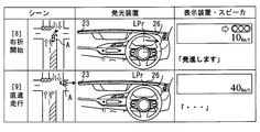
- the presentation mode of the light emitting device 23 transitions from the vehicle behavior mode to the action induction mode.
- the light emitting device 23 prompts the driver to confirm the status of the unrecognizable area RA3 by the induced light emission spot 27 (see [4] in FIG. 31).
- the display device 22 displays an overhead view of the intersection indicating the position of the unrecognizable area RA3 and a message for prompting safety confirmation and permission to start.
- a voice message “Please check the surrounding safety and press the start button” is uttered from the speaker 21 (see FIG. 2).
- the light-emitting device 23 splits the induced light-emitting spot 27 lit at the lighting reference position LPr left and right in [4] in FIG. 31, and moves it to the direction of the unrecognizable area RA3.
- the DSM 11 detects the driver's visual recognition direction, as shown in FIG. 34, the induced light emission spot 27 is split left and right after moving from the lighting reference position LPr toward the gazing point PG. Also good.
- the light emitting device 23 fades out the induced light spot 27 after repeating the movement of the guided light spot 27 a plurality of times (see [5] in FIG. 31).
- the induced light emission spots 27 are sequentially turned off based on the situation confirmation of the unrecognizable area RA3 by the driver.
- FIG. 35 when the driver's gazing point PG is directed to the unrecognizable area RA3 that is in the right direction when viewed from the driver, the right direction light emitting spot 27 is turned off.
- the left guide light emission spot 27 is turned off.
- the guide light emission spot 27 is turned off after a lapse of a certain time from the start of lighting.
- the presentation mode transitions from the behavior induction mode to the state notification mode in accordance with the timing when the information presentation in the behavior induction mode is completed and the induced light emission spot 27 is turned off.
- the automatic driving system 90 enters a standby state waiting for the driver's operation to be permitted to start.
- the automatic driving system 90 transitions to an on state.
- the presentation mode of the light emitting device 23 also transitions from the state notification mode to the vehicle behavior mode.
- the light emitting device 23 repeatedly displays an animation for moving the preceding light emitting spot 26 to the right from the lighting reference position LPr (see [6] in FIG. 31).
- the autonomous running is resumed.
- the vehicle A transitions to straight running due to the completion of the right turn the preceding light emission spot 26 is turned on at the lighting reference position LPr (see [7] in FIG. 31).
- Vehicle A in which the automatic driving system 90 is in an on state travels straight by autonomous traveling and approaches an intersection of green lights (see [1] in FIG. 36).
- the light emitting device 23 is presenting information in the vehicle behavior mode, and lights the preceding light emitting spot 26 at the lighting reference position LPr.
- the speaker 21 (see FIG. 2) utters a voice message saying “I will turn right at the intersection.
- the right direction indicator starts blinking.
- the light emitting device 23 will give notice of deceleration. Specifically, an animation for contracting the preceding light emitting spot 26 is displayed on the light emitting device 23 to the lighting width corresponding to the vehicle speed after several seconds set in the travel plan (see [2] in FIG. 36).
- the automatic driving system 90 causes the vehicle A, which has been slowly decelerated, to enter the right turn lane. A few seconds before entering the right turn lane, the light emitting device 23 repeatedly displays an animation for moving the preceding light emitting spot 26 to the right from the lighting reference position LPr (see [3]).
- the movement width of the preceding light-emitting spot 26 in the right direction is a movement width corresponding to the steering amount after several seconds set in the travel plan.
- the light-emitting device 23 When the vehicle A stops at the intersection, the light-emitting device 23 lights the preceding light-emitting spot 26 at the lighting reference position LPr with a lighting width corresponding to when the vehicle is stopped (0 km / h) (see [4] in FIG. 36). . When the vehicle A stops due to a red light, the light-emitting device 23 changes to the state [4] without repeating the information [3] after repeating [1] and [2] in FIG. 36. To do.
- the light-emitting device 23 When the unrecognizable area RA3 has occurred in the vicinity of the intersection, the light-emitting device 23 presents information in the behavior induction mode, and prompts the driver to confirm the status of the unrecognizable area RA3 by the induced light emission spot 27 ( (See [5] in FIG. 36). Specifically, the light-emitting device 23 splits the induced light-emitting spot 27 lit at the lighting reference position LPr to the left and right, and moves a part thereof to the position of the unrecognizable area RA3 in the right direction (see FIG. 38). At this time, the display device 22 displays an overhead view of the intersection indicating the position of the unrecognizable area RA3 and a message for prompting safety confirmation and permission to start. In addition, a voice message “Please check the surrounding safety and press the start button” is uttered from the speaker 21 (see FIG. 2).
- the light emitting device 23 repeats the movement of the induced light emission spot 27 a plurality of times, and then fades out the induced light emission spot 27 (see [6] in FIG. 36).
- the guided light emission spots 27 are sequentially turned off based on the confirmation action of the unrecognizable area RA3 by the driver.
- the guide light emission spot 27 is turned off after a lapse of a certain time from the start of lighting.
- the presentation mode transitions from the behavior induction mode to the state notification mode at the timing when the action induction presentation in the action induction mode is completed and the induced light emission spot 27 is turned off.
- the automatic driving system 90 holds the start permission by the driver at the timing when the oncoming vehicle is detected as a risk target, and maintains the stop state of the vehicle A.
- the presentation mode of the light emitting device 23 transitions from the state notification mode to the preventive safety mode.
- the notification light emission spot 28 is turned on in the direction of the oncoming vehicle that is the risk target (see [7] in FIG. 36).
- a voice message “Waiting for the oncoming vehicle to pass” is uttered from the speaker 21 (see FIG. 2).
- the vehicle A When the risk target disappears due to the passing of the oncoming vehicle intersection, the vehicle A starts making a right turn at the intersection. At this time, the presentation mode of the light-emitting device 23 transitions from the preventive safety mode to the vehicle behavior mode as the risk is eliminated. As a result, an animation for moving the preceding light emission spot 26 from the lighting reference position LPr to the right is repeatedly displayed (see [8] in FIG. 37). After the information presentation by the movement of the preceding light emitting spot 26 and the utterance of the voice message “I will start”, the autonomous running is resumed. Then, when the vehicle A goes straight ahead upon completion of the right turn, the preceding light emission spot 26 is turned on at the lighting reference position LPr (see [9] in FIG. 37).
- the capability limit of the peripheral monitoring device 70 is controlled by the light emission control of the light emitting device 23 implemented in each presentation mode.
- the occupant of the vehicle A can obtain a clue to know the capability limit of the periphery monitoring device 70 on many occasions. Therefore, the HCU 30 can reduce the anxiety of the occupant about the driving environment recognition in the vehicle A.
- the driver can almost always recognize the clue to know the capacity limit, so that the vehicle A can be aware of misrecognition and unrecognition in the recognition of the driving environment while the risk level of the vehicle A is low. .
- the driver can supplement the automatic driving system 90 and cope with the risk. If such a response is possible, the driver's sense of security with respect to automatic driving is less likely to be impaired.
- the presentation mode is switched based on the presence / absence of the unrecognizable area RA3 indicating the capability limit of the periphery monitoring device 70. According to such transition of the presentation mode, it is possible to perform information presentation that prompts the driver to perform an action that complements the capacity limit after the automatic driving system 90 self-detects the occurrence of the capacity limit.
- display is performed in which the preceding light emission spot 26 is superimposed on the notification light emission spot 28 due to the occurrence of a risk target.
- Such information presentation makes it easier for the passenger to grasp the situation. As a result, the occupant can calmly cope with a sudden behavior change by the automatic driving system 90 for dealing with the risk target.
- the relative position of the unrecognizable area RA3 is presented according to the direction of the guide light emission spot 27 viewed from the driver.
- the occupant can easily grasp the generation range of the capability limit of the automatic driving system 90 and can smoothly complement the capability limit. Therefore, even if the capacity limit occurs, an increase in passenger anxiety is unlikely to occur.
- the induced light emission spot 27 in the present embodiment moves toward the unrecognizable area RA3. According to such presentation, it is possible to induce the driver to visually recognize the unrecognizable area RA3. As described above, if the occupant's supplementary behavior is promoted by the behavior of the induced light spot 27, the anxiety of the occupant to the vehicle A displaying the induced light spot 27 can be reduced.
- the light emitting device 23 can transmit the existence of a large number of unrecognizable areas RA3 to the occupant without omission while avoiding a situation in which the occupant is confused by the light emission of the large number of induced light spots 27.
- the automatic driving system 90 stops autonomous traveling and enters a standby state. Therefore, if the state is changed to the state notification mode indicating the standby state in accordance with the extinction of the guide light emission spot, the suspension of the autonomous traveling is clearly shown to the driver who has confirmed the unrecognizable area RA3. As a result, the driver is prompted to input an operation that permits the resumption of autonomous driving.
- the lighting reference position LPr is switched according to the automation level of autonomous driving. Such switching makes it easier for the occupant to grasp the automation level. And according to the state grasp of the automation level, the anxiety of the occupant to the automatic driving system 90 is further reduced.
- the unrecognizable area RA3 is set based on the difference between the required recognition range RA1 and the assumed recognition range RA2. According to such processing, the unrecognizable area RA3 can be appropriately set within a range that is a capability limit of the periphery monitoring device 70 and needs to be supplemented by the driver. Therefore, a situation in which the driver's load for supplementing the automatic driving system 90 and the periphery monitoring device 70 is unnecessarily increased is avoided.
- the light emission colors of the light emission spots 25 in each presentation mode are different from each other. Therefore, even if the presentation mode is switched among a plurality, the light emitting device 23 can present to the occupant without confusing the state of the automatic driving system 90. As a result, the passenger's sense of security can be further improved.
- the light emitting device 23 corresponds to the “light emitting unit”
- the positions 27r and 27l correspond to “both end positions”
- the presentation control unit 35 corresponds to the “light emitting control unit”
- the HCU 30 It corresponds to a “presentation control device”.
- the capability limit of the peripheral monitoring device was presented.
- the number of presentation modes set in the HCU is not limited to four, and may be five or more, for example.
- the number of presentation modes for presenting capability limits may be three or more.
- the presentation mode for presenting the capability limit may be all or a part of a plurality of preset presentation modes.
- information serving as a trigger for switching each presentation mode is not limited to the presence or absence of an unrecognizable area as in the above embodiment. Various information related to the state of the vehicle can be used as trigger information for changing the presentation mode.
- the future behavior presentation in the vehicle behavior mode and the direction presentation of the unrecognizable area in the behavior induction mode correspond to presentation of the capability limit, respectively.
- the method of presenting the capability limit in each presentation mode may be changed as appropriate.
- the content of the animation using the light emission spot in the vehicle behavior mode and the behavior induction mode may be changed as appropriate.
- the directions of the individual unrecognizable areas may be presented individually by lighting a large number of induced light emission spots.
- the emission colors defined for each presentation mode may not be all different. That is, the emission colors defined in some presentation modes may be substantially the same. When the two emission colors are set differently, it is desirable that these emission colors are separated by a predetermined angle or more on the hue circle.
- the configuration of the light emitting device for displaying the light emitting spots can be changed as appropriate.
- a linear extending region that displays a movable light emitting spot may be realized by using a self-luminous panel such as an organic EL formed in a band shape.
- the installation position of the light emitting device can be changed as appropriate.
- the light emitting device may be installed above the windshield in a shape along the upper edge of the windshield.
- the light emitting device may be installed below the windshield and project light onto the lower edge region of the windshield. In this configuration, each passenger sees the reflected light reflected by the lower edge region of the windshield. That is, the light emitting device may be a virtual image display device that allows a passenger to visually recognize a virtual image of a light emitting spot.
- an automatic driving system capable of changing the automation level of autonomous driving has been assumed.
- the automation level of autonomous driving realized by the automatic driving system may not be changeable.
- the automatic driving system is a system that performs only autonomous level 2 or 3 autonomous traveling, and may be a system that does not perform autonomous level 4 or higher autonomous traveling. Even if it is such a form, the change of the light emission mode of the light-emitting device according to an automation level may not be implemented.
- the definition of the automation level is not limited to the above definition and can be changed as appropriate.
- the function provided by the control circuit of the HCU can be provided by hardware and software different from those described above, or a combination thereof.
- Various non-transitory physical storage media can be employed for the memory device 63 (see FIG. 1) that stores the presentation control program.
- the storage medium for storing the presentation control program is not limited to the memory device of the HCU, and may be an optical disk serving as a copy source to the memory device, a hard disk drive of a general-purpose computer, or the like.
- each unit is expressed as, for example, S101.
- each part can be divided into a plurality of sub-parts, while the plurality of parts can be combined into one part.
- each part configured in this manner can be referred to as a circuit, a device, a module, and a means.
- each of the plurality of parts described above or a combination thereof includes not only (i) a software part combined with a hardware unit (for example, a computer) but also (ii) hardware (for example, an integrated circuit, As a part of the (wiring logic circuit), it can be realized with or without including the functions of related devices.
- the hardware unit can be configured inside a microcomputer.
Landscapes
- Engineering & Computer Science (AREA)
- Radar, Positioning & Navigation (AREA)
- Remote Sensing (AREA)
- Automation & Control Theory (AREA)
- Physics & Mathematics (AREA)
- General Physics & Mathematics (AREA)
- Transportation (AREA)
- Mechanical Engineering (AREA)
- Human Computer Interaction (AREA)
- Chemical & Material Sciences (AREA)
- Combustion & Propulsion (AREA)
- Traffic Control Systems (AREA)
- Navigation (AREA)
- Control Of Driving Devices And Active Controlling Of Vehicle (AREA)
- Instrument Panels (AREA)
Abstract
周辺監視装置(70)を搭載する車両(A)において用いられ、車両に設けられた発光部(23)の発光制御によって情報を提示する提示制御装置を提供する。提示制御装置は、周辺監視装置による走行環境認識に関連した認識情報を取得する情報取得部(31)と、発光部を用いた情報提示を複数の提示モードのうちで切り替えるモード切替部(34)と、認識情報を用いた発光部の発光制御により、周辺監視装置の能力限界を、複数の提示モードにおいて提示する発光制御部(35)と、を備える。
Description
本出願は、2018年2月8日に出願された日本特許出願番号2018-21189号に基づくもので、ここにその記載内容を援用する。
この明細書による開示は、車両の乗員に情報を提示する提示制御装置、及び提示制御プログラムに関する。
従来、例えば特許文献1に開示の車両は、走行環境認識部による車両の周辺の認識結果に基づく自動運転を実行可能である。こうした走行環境認識部には、能力限界が不可避的に存在する。そのため、特許文献1の車両には、警報装置が搭載されている。警報装置は、自動運転を継続不能である場合に、ステアリングホイールに設けられた発光部を発光させる情報提示により、運転者にステアリングホイールの把持を促す。
特許文献1の警報装置では、自動運転が継続不能となる限られたタイミングにおいてのみ、走行環境認識部の能力限界が、車両の乗員に提示される。そのため車両の乗員は、乗車中の多くの機会において、走行環境認識部の能力限界を知る手がかりを得ることができない。その結果、車両の乗員は、走行環境認識部による周辺認識に対して、不安を感じ易くなり得た。
本開示は、車両における走行環境認識への乗員の不安を低減可能な提示制御装置及び提示制御プログラムの提供を目的とする。
本開示の一態様による提示制御装置は、周辺監視装置を搭載する車両において用いられ、車両に設けられた発光部の発光制御によって情報を提示する提示制御装置であって、周辺監視装置による走行環境認識に関連した認識情報を取得する情報取得部と、発光部を用いた情報提示を複数の提示モードのうちで切り替えるモード切替部と、認識情報を用いた発光部の発光制御により、周辺監視装置の能力限界を、複数の提示モードにおいて提示する発光制御部と、を備える提示制御装置とされる。
本開示の他の態様による提示制御プログラムは、周辺監視装置を搭載する車両において用いられ、車両に設けられた発光部の発光制御によって情報を提示する提示制御プログラムであって、少なくとも一つの処理部を、周辺監視装置による走行環境認識に関連した認識情報を取得する情報取得部、発光部を用いた情報提示を複数の提示モードのうちで切り替えるモード切替部、認識情報を用いた発光部の発光制御により、周辺監視装置の能力限界を、複数の提示モードにおいて提示する発光制御部、として機能させる提示制御プログラムとされる。
これらの態様によれば、発光部を用いた情報提示の提示モードが切り替えられても、周辺監視装置の能力限界は、各提示モードにおいて実施される発光部の発光制御により、車両の乗員に提示される。以上によれば、車両の乗員は、周辺監視装置の能力限界を知る手がかりを乗車中の多くの機会において得られるようになる。したがって、提示制御装置及び提示制御プログラムによる情報提示は、車両における走行環境認識への乗員の不安を低減できる。
本開示についての上記目的およびその他の目的、特徴や利点は、添付の図面を参照しながら下記の詳細な記述により、より明確になる。その図面は、
図1は、運転席周辺における情報提示システムのレイアウト等を示す図であり、
図2は、HCUを含む車載システムの全体像を示すブロック図であり、
図3は、自動運転システムの作動状態の遷移を示す状態遷移図であり、
図4は、情報提示のタイミング及び余裕時間の考え方を説明するための図であり、
図5は、エリア特定処理の詳細を示すフローチャートであり、
図6は、要求認識範囲及び想定認識範囲を例示する図であり、
図7は、認識不可エリアを例示する図であり、
図8は、発光装置の複数の提示モードの全体像を示す状態遷移図であり、
図9は、提示モードを切り替えるモード変更処理の詳細を示すフローチャートであり、
図10は、状態通知モードにて実施される状態通知処理の詳細を示すフローチャートであり、
図11は、車両挙動モードにて実施される前後挙動提示処理の詳細を示すフローチャートであり、
図12は、先行発光スポットの点灯幅を設定する点灯幅設定関数の一例を示す図であり、
図13は、先行発光スポットの移動又は収縮の繰り返し周期を設定する周期設定関数の一例を示す図であり、
図14は、報知発光スポットに先行発光スポットを重ねて表示する場合の表示例であり、
図15は、車両挙動モードにて実施される左右挙動提示処理の詳細を示すフローチャートであり、
図16は、先行発光スポットの点灯位置を設定する位置設定関数の一例を示す図であり、
図17は、図11とは別の前後挙動提示処理の詳細を示すフローチャートであり、
図18は、先行発光スポットの移動又は収縮の繰り返し周期を設定する周期設定関数の一例を示す図であり、
図19は、図15とは別の左右挙動提示処理の詳細を示すフローチャートであり、
図20は、将来挙動の提示タイミングを設定するタイミング設定処理の詳細を示すフローチャートであり、
図21は、提示情報の詳細度を設定する詳細度設定処理の詳細を示すフローチャートであり、
図22は、行動誘発モードにて実施される能力限界提示処理の詳細を示すフローチャートであり、
図23は、複数(四つ)の認識不可エリアが発生するシーンの一例を示す図であり、
図24は、図23のシーンにおける発光装置の点灯状態を示す図であり、
図25は、複数(三つ)の認識不可エリアが発生するシーンの一例を示す図であり、
図26は、図25のシーンにおける発光装置の点灯状態を示す図であり、
図27は、自動化レベル毎に異なる先行発光スポットの点灯態様を比較して示す図であり、
図28は、自動化レベル毎に異なる誘導発光スポットの点灯態様を比較して示す図であり、
図29は、自動化レベル毎に異なる報知発光スポットの点灯態様を比較して示す図であり、
図30は、自動化レベル提示処理の詳細を示すフローチャートであり、
図31は、ユースケース1での情報提示システムによる情報提示を順に示す図であり、
図32は、ユースケース1での前後挙動提示の詳細を示す図であり、
図33は、ユースケース1での行動誘発提示の詳細を示す図であり、
図34は、図33とは別パターンによる行動誘発提示の詳細を示す図であり、
図35は、運転者の確認行動に伴って誘導発光スポットをフェードアウトさせる方法の一例を示す図であり、
図36は、ユースケース2での情報提示を図37と共に示す図であり、
図37は、ユースケース2での情報提示を図36と共に示す図であり、
図38は、ユースケース2での行動誘発提示の詳細を示す図である。
本開示の一実施形態による提示制御装置の機能は、図1及び図2に示すHCU(HMI(Human Machine Interface)Control Unit)30によって実現されている。HCU30は、車両制御ECU(Electronic Control Unit)80及び自動運転ECU50等の電子制御ユニットと共に車両Aに搭載されている。車両制御ECU80及び自動運転ECU50は、運転者に代わって運転操作を行う自動運転機能を実現する処理装置であって、協調して車両Aを自律走行させることができる。HCU30、自動運転ECU50及び車両制御ECU80は、直接的又は間接的に互い電気接続されており、相互に通信可能である。
車両制御ECU80は、車両Aに搭載された車載センサ群82及び車載アクチュエータ群83と直接的又は間接的に電気接続されている。車載センサ群82は、車両Aの状態を検出する複数のセンサである。車載センサ群82には、例えば車速センサ、舵角センサ、加速度センサ、アクセルポジションセンサ及びブレーキペダルセンサが含まれている。車載アクチュエータ群83は、車両Aの加減速制御及び操作制御等を実行する。車載アクチュエータ群83には、例えば電子制御スロットルのスロットルアクチュエータ、インジェクタ、ブレーキアクチュエータ、並びに駆動用及び回生用のモータジェネレータが含まれている。
車両制御ECU80は、処理部、RAM、メモリ装置、及び入出力インターフェース等を有するコンピュータを主体に構成されている。車両制御ECU80は、メモリ装置に記憶された車両制御プログラムを処理部によって実行することにより、車両制御に係る機能ブロックとしてアクチュエータ制御部81を構築する。アクチュエータ制御部81は、運転者の運転操作に基づく操作情報及び自動運転ECU50から取得される自律走行情報の少なくとも一方と、車載センサ群82の検出情報とに基づき、車載アクチュエータ群83を統合的に作動させ、車両Aの挙動を制御する。
自動運転ECU50は、GNSS(Global Navigation Satellite System)受信機71、地図データベース72、自律センサ群73、自動運転スイッチ76等と直接的又は間接的に電気接続されている。自動運転ECU50は、自律走行に必要な情報を取得する構成であるGNSS受信機71、地図データベース72及び自律センサ群73等と共に、車両Aにおける自動運転システム90を構築している。
GNSS受信機71は、複数の人工衛星から送信された測位信号を受信可能である。GNSS受信機71は、受信した測位信号を、車両Aの現在位置を特定するための情報として、自動運転ECU50へ向けて逐次出力する。
地図データベース72は、多数の地図データを格納している記憶装置である。地図データには、各道路の曲率、勾配、区間の長さといった道路構造情報、道路周囲の建築物の形状等を示す建築物情報、並びに制限速度及び一方通行といった非一時的な交通規制情報等が含まれている。地図データベース72は、自動運転ECU50からの要求に基づき、車両Aの現在位置の周辺及び進行方向の地図データを自動運転ECU50に提供する。
自律センサ群73は、歩行者及び他の車両等の移動物体、さらに路上の落下物、交通信号、ガードレール、縁石、道路標識、道路標示、及び区画線等の静止物体を検出する。自律センサ群73には、例えばカメラユニット、ライダユニット及びミリ波レーダユニット等が含まれている。自律センサ群73はそれぞれ、検出した移動物体及び静止物体に係る物体情報を、自動運転ECU50へ向けて逐次出力する。
自動運転スイッチ76は、自動運転システム90の作動状態を切り替える入力装置である。自動運転スイッチ76は、例えばステアリングホイール113のスポーク部分に設けられている。自動運転スイッチ76には、例えばSET/ONボタン及びCancel/OFFボタンが含まれている。
図3に示すように、自動運転システム90(図2参照)がオフ状態(AD_OFF)である場合にSET/ONボタンが操作されると、自動運転システム90の状態は、待機状態(AD_Ready)に遷移する。そして、待機状態でのSET/ONボタンの操作により、自動運転システム90による自律走行が開始される(AD_ON)。また、自律走行中でのCancel/OFFボタンの操作によれば、自動運転システム90の状態は、待機状態に戻る。さらに、待機状態でのCancel/OFFボタンの操作により、自動運転システム90は、オフ状態となる。
図2に示す自動運転システム90は、自動化レベルの異なる自律走行を実施可能である。自動化レベルは、一例としてSociety of Automotive Engineersの定義等を用いて設定できる。具体的に、自動化レベル0~2では、運転者が主体となって運転操作を実施する。このとき、自動運転システム90は、オフ状態又は待機状態(自動化レベル0)であるか、或いは運転者の運転操作を支援する状態(自動化レベル1~2)である。一方で、自動化レベル3~5では、自動運転システム90が主体となって運転操作を実施する。以上のような自動化レベルは、運転者によって切り替え可能であってもよく、走行エリアに対し許可される自動化レベルに合わせて自動的に変更されてもよい。
自動運転ECU50は、処理部61、RAM62、メモリ装置63及び入出力インターフェースを有するコンピュータを主体に構成されている。処理部61は、CPU(Central Processing Unit)、GPU(Graphics Processing Unit)及びFPGA(Field-Programmable Gate Array)等の少なくとも一つを含む構成である。処理部61には、AI(Artificial Intelligence)の学習及び推論に特化した専用のアクセラレータが設けられていてもよい。
自動運転ECU50は、メモリ装置63に記憶された自動運転プログラムを処理部61によって実行可能である。自動運転プログラムには、車両Aを自律走行させるためのプログラムと、運転者及び自動運転システム90間での運転交代を制御するためのプログラム等が含まれている。自動運転プログラムに基づき、自動運転ECU50には、自車位置特定部51、環境認識部52、走行計画生成部53及び自律走行制御部54等が構築される。
自車位置特定部51は、GNSS受信機71にて受信された測位信号に基づき、車両Aの現在位置を特定する。自車位置特定部51は、自律センサ群73のカメラユニットから取得する前方領域の画像と、地図データベース72から取得する詳細な地図データとの照合により、車両Aの詳細な現在位置を補正する。
環境認識部52は、自車位置特定部51にて特定された位置情報、地図データベース72から取得した地図データ、及び自律センサ群73から取得した物体情報等を組み合わせることで、車両Aの周囲の走行環境を認識する。環境認識部52は、特に各自律センサの検出範囲内について、各物体情報の統合結果に基づき、車両Aの周囲の物体の形状及び移動状態を認識した認識結果を取得する。環境認識部52は、自律センサ群73と共に周辺監視装置70の機能を実現する。環境認識部52は、車両Aの周囲の認識結果と、位置情報及び地図データと組み合わせることで、実際に認識した走行環境を三次元で再現した仮想空間を生成する。尚、以下の説明では、環境認識部52及び自律センサ群73を含めた機能部分を、周辺監視装置70と記載する。
走行計画生成部53は、環境認識部52によって認識された走行環境に基づき、自動運転システム90によって車両Aを自律走行させるための走行計画を生成する。走行計画としては、長中期の走行計画と、短期の走行計画とが生成される。長中期の走行計画では、運転者によって設定された目的地に車両Aを向かわせるための経路が規定される。短期の走行計画では、環境認識部52にて生成された仮想空間を用いて、長中期の走行計画に従った走行を実現するための予定走行経路が規定される。具体的に、車線追従、車線変更及び右左折のための操舵、並びに速度調整及び一時停止のための加減速等の実行が、短期の走行計画に基づいて決定される。
自律走行制御部54は、自動運転モードにて、走行計画生成部53によって策定された予定走行経路に基づく内容の加減速及び操舵を指示する自律走行情報を生成する。自律走行制御部54は、生成した自律走行情報を車両制御ECU80へ向けて逐次出力する。自律走行制御部54は、アクチュエータ制御部81と連携し、予定走行経路に沿って車両Aを自律走行させる。
HCU30は、乗員監視システム10及び情報提示システム20等とさらに接続されている。乗員監視システム10は、主に運転席110(図1参照)に着座する運転者の状態を監視するシステムである。乗員監視システム10には、DSM(Driver Status Monitor)11、足センサ12及び把持センサ13が含まれている。
DSM11は、近赤外光源及び近赤外カメラと、これらを制御する制御ユニット等とによって構成されている。DSM11は、近赤外カメラを運転席側に向けた姿勢にて、例えばインスツルメントパネルの上面等に配置されている。DSM11は、運転者の状態監視のため、近赤外光源によって近赤外光を照射された運転者の上半身を近赤外カメラで撮影する。DSM11は、撮影した画像を検出情報として、HCU30へ向けて逐次出力する。
足センサ12は、光の照射によって物体を検出するアクティブ型の物体検出センサである。足センサ12の検出範囲は、特にアクセルペダル及びブレーキペダルを含むように設定されている。足センサ12は、フロア、アクセルペダル及びブレーキペダル等のうちで、運転者の足が置かれている位置を検出し、HCU30へ向けて検出情報を逐次出力する。
把持センサ13は、ステアリングホイール113(図1参照)のリム部分に設けられ、運転者によるステアリングホイール113の把持を検出する。把持センサ13は、ステアリングホイール113を運転者が把持しているか否かを示す検出情報を、HCU30へ向けて逐次出力する。
情報提示システム20は、運転者を含む車両Aの各乗員へ向けて、車両Aに関連する情報を提示するシステムである。情報提示システム20には、スピーカ21、表示装置22及び発光装置23等の提示デバイスが含まれている。スピーカ21は、例えば警告音及び音声メッセージ等を再生可能である。表示装置22は、例えば液晶ディスプレイ等を主体に構成されている。表示装置22は、表示面を運転席110へ向けた姿勢で、インスツルメントパネルに設置されている。表示装置22は、種々の画像及び文字等を、表示画面に表示可能である。
図1及び図2に示す発光装置23は、運転者の前方に位置するように、車両のインスツルメントパネルに設置されている。発光装置23は、線状延伸領域24に発光表示させる発光スポット25の発光態様により、乗員に情報を提示する提示装置である。線状延伸領域24は、車両Aの幅方向WDに沿って線状に延伸している。線状延伸領域24の内部には、幅方向WDに沿って並ぶ多数の発光素子(例えばLED)が設けられている。発光装置23は、線状延伸領域24に表示させる発光スポット25の数、サイズ、位置、移動方向、移動速度、発光色(色相、彩度、明度)及び発光輝度等を変更可能である。尚、各図における線状延伸領域24では、濃いドットの範囲が消灯領域を示し、白色又はごく薄いドットの範囲が発光スポット25となる発光領域を示している。
HCU30は、情報提示システム20を用いた運転者への情報提示を統合的に制御する電子制御ユニットである。HCU30は、処理部41、RAM42、メモリ装置43、及び入出力インターフェース等を有するコンピュータを主体に構成されている。処理部41は、CPU、GPU及びFPGA等の少なくとも一つを含む構成である。処理部41には、処理部61と同様に、AIの学習及び推論に特化した専用のアクセラレータが設けられていてもよい。
HCU30は、メモリ装置43に記憶された提示制御プログラムを処理部41によって実行可能である。提示制御プログラムには、運転者の状態推定に関連したプログラムと、情報提示システム20の作動制御に関連したプログラム等が含まれている。提示制御プログラムに基づき、HCU30には、情報取得部31、モード切替部34及び提示制御部35等が構築される。
情報取得部31は、乗員監視システム10、自動運転ECU50及び車両制御ECU80等から、情報提示システム20を用いた提示に必要な種々の情報を取得する。具体的に、情報取得部31は、自動運転システム90のステータス情報、車両Aの走行状態を示す車両状態情報、乗員監視システム10による運転者の検出情報、周辺監視装置70による走行環境認識に関連した認識情報等を取得する。情報取得部31は、情報提示に必要な各情報を通信によって取得してもよく、又は通信によって取得した情報を加工する処理によりこれらの各情報を取得してもよい。
ステータス情報は、例えば自動運転システム90の作動状態を示す情報、及び自律走行の自動化レベルを示す情報を含んでいる。車両状態情報は、車速センサを用いて計測された車両Aの速度情報、舵角センサを用いて計測された車両Aの操舵情報、車両Aの現在位置を示す情報、及び周囲の走行環境の状態を示す環境情報等を含んでいる。検出情報は、DSM11、足センサ12及び把持センサ13から出力された検出結果である。認識情報は、周辺監視装置70にて認識された物体の相対位置情報、認識結果を用いて作成された短期の走行計画、及び認識不可エリアRA3(図7参照)の方向を示す方向情報を含んでいる。
情報取得部31は、サブ機能ブロックとして乗員状態判定ブロック32及び認識状態判定ブロック33を有している。乗員状態判定ブロック32及び認識状態判定ブロック33は、上述したように、乗員監視システム10、自動運転ECU50及び車両制御ECU80から提供される情報を用いて、情報提示に必要な情報を生成する機能部である。
乗員状態判定ブロック32は、乗員監視システム10による検出情報を用いて、運転者の状態を判定する。具体的に、乗員状態判定ブロック32は、運転者の視認方向、ステアリングホイール113及び他の操作系の把持の有無、ブレーキペダルを踏める位置に足が位置しているか否か等、運転姿勢に関連した判定を実施する。加えて乗員状態判定ブロック32は、運転者の表情、瞬きの回数、手及び脚の動き、並びに上記の運転姿勢等に基づき、予め設定された演算式を用いて、運転者の不安度を算定する。こうした不安度の算定には、運転者の心拍数等の情報がさらに用いられてもよい。心拍数は、例えば運転者の着用するウェアラブルデバイス等によって計測され、無線通信等によってHCU30に送信される。尚、運転姿勢及び不安度を示す情報は、乗員監視システム10にて生成され、情報取得部31に逐次提供されてもよい。こうした形態では、乗員状態判定ブロック32は、省略可能となる。
認識状態判定ブロック33は、周辺監視装置70による認識結果を用いて、車両Aの走行環境を判定する。具体的に、認識状態判定ブロック33は、周辺監視装置70にて認識された物体の中から、乗員への注意喚起の対象とするリスク対象を選別する。加えて認識状態判定ブロック33は、周辺監視装置70によって認識できない認識不可エリアRA3(図6参照)の存在を把握する。尚、リスク対象を選別する演算及び認識不可エリアRA3を把握する演算は、環境認識部52にて実施されてもよい。これらの演算結果が共に情報取得部31に提供される形態であれば、認識状態判定ブロック33は、省略可能となる。
リスク対象は、相対位置情報の示す物体のうちで、車両Aに対する余裕時間Raがマイナスとなる物体である。余裕時間Raは、物体の認知、判断及び操作によって物体に対応するために必要な最低限の時間である。余裕時間Raは、運転者の反応時間RT及び運転者の反応遅れ時間RDTと、制動操作又は操舵操作によって対応するために必要な時間Dとの合計となる(図4参照)。認識状態判定ブロック33は、相対位置情報に基づき、各認識物体の余裕時間Raを算出し、余裕時間Raが負の値(マイナス)となる認識物体をリスク対象として選別する。
認識不可エリアRA3は、周辺監視装置70の能力限界となる範囲であり、自律走行に必要なセンシング範囲と、現在のセンシング可能範囲との差分から算出する。具体的に、認識状態判定ブロック33は、自動運転システム90によって要求される要求認識範囲RA1(図6参照)と、周辺監視装置70による実際の認識が想定される想定認識範囲RA2(図6参照)との差分を用いて、認識不可エリアRA3を設定する。認識状態判定ブロック33は、認識不可エリアRA3の発生と、運転者から見た認識不可エリアRA3の方向とを、エリア特定処理(図5参照)によって特定する。エリア特定処理の少なくとも一部は、例えば環境認識部52によって実行されてもよい。エリア特定処理は、車両電源のオン状態への切り替えに基づき開始され、車両電源がオフ状態となるまで継続される。
図5に示すエリア特定処理のS101では、現在位置を示す情報を取得し、S102に進む。S102では、周囲を走行する他車両の想定速度Vs(m/s)を取得し、S103に進む。想定速度Vsは、例えば制限速度に特定値(例えば20km/h≒5.6m/s)を加えた値、又は普段の交通量において95%の車両を含むことができる値等に設定される。また、歩行者及びサイクリストを対象とする場合、想定速度Vsは、蓄積された普段の速度データを用いて設定可能であり、例えば平均の移動速度に2σ(σ:速度の標準偏差)を加えた値に設定される。
S103では、走行計画に基づく数秒後の自車(車両A)の挙動を取得し、S104に進む。S104では、S103にて取得した自車挙動にかかる予想所要時間T(s)を取得し、S105に進む。例えば、自車挙動として右折が計画されていた場合、6~7秒の予想所要時間Tを取得する。
S105では、要求認識範囲RA1を算出し、S106に進む。要求認識範囲RA1は、主に地図データを用いて算出され、具体的には、車両Aを中心とし、S102にて取得した想定速度VsとS104にて取得した予想所要時間Tとの積を半径とする円形の範囲とされる(図6参照)。S106では、車両Aの周囲の環境情報として、周囲の視界の良否を考慮するための天候情報、時間帯情報、及び見通し情報等を取得し、S107に進む。見通し情報は、地図データ等に基づく道路脇の遮蔽物の有無及び形状等を示す情報である。
S107では、S106にて取得した環境情報を用いて、想定認識範囲RA2を算出し、S108に進む。想定認識範囲RA2は、自律センサ群73(図2参照)の最大検出範囲を、S106にて取得した環境情報を用いて狭める処理によって取得される。遮蔽物BOの死角となる範囲は、想定認識範囲RA2から外れるようになる(図7参照)。
S108では、要求認識範囲RA1と想定認識範囲RA2との差分に基づき、認識不可エリアRA3として算出し、S109に進む。S109では、地図データに示された道路形状に認識不可エリアRA3をフィッティングさせ(図7参照)、リスク対象の存在可能な範囲に認識不可エリアRA3を設定し、S110に進む。こうした処理により、塀等の遮蔽物BOによって自車からは死角となる範囲の道路上に、認識不可エリアRA3が設定される。
S110では、S109にて抽出された少なくとも一つの認識不可エリアRA3(図7参照)の相対位置に基づき、運転者から見た認識不可エリアRA3の方向を設定する。複数の認識不可エリアRA3が存在する場合には、複数の方向が設定される(図23及び図25等も参照)。以上の処理の繰り返しにより、情報取得部31(図2参照)は、認識不可エリアRA3の方向情報を逐次取得可能となる。
図2及び図8に示すように、モード切替部34は、情報提示システム20を用いた情報提示を、車両Aの状態に応じて、複数の提示モードのうちで切り替える。HCU30には、状態通知モード、予防安全モード、車両挙動モード及び行動誘発モードという四つの提示モードが予め設定されている。提示モードの切り替えのトリガとなる車両Aの状態には、車両A自体の状態、リスク対象を検出しているか否かといった走行環境に起因する車両Aの状態、及び特定操作が入力されたか否かといった運転者に起因する車両Aの状態も含まれる。
モード切替部34は、通常の自律走行中において、提示モードを車両挙動モードとする。モード切替部34は、自律走行中にリスク対象が発生した場合(Ra<0)、車両挙動モードから予防安全モードへと提示モードを切り替える。そして、リスク対象の消失によってリスクが解消された場合には(Ra≧0)、モード切替部34は、予防安全モードから車両挙動モードへと提示モードを切り替える。一方、モード切替部34は、自律走行中に認識不可エリアRA3(図7参照)が発生した場合、車両挙動モードから行動誘発モードへと提示モードを切り替える。そして、行動誘発モードでの情報提示が終了すると、モード切替部34は、状態通知モードへと提示モードを遷移させる。このとき、自動運転システム90は、待機状態となる。
自動運転システム90による自律走行を再開させる操作が運転者によって入力され、車両Aの周囲にリスク対象が存在しない場合(Ra≧0)、モード切替部34は、状態通知モードから車両挙動モードへと提示モードを遷移させる。一方、自律走行を再開させる操作が運転者によって入力されたとき、リスク対象が存在している場合(Ra<0)、モード切替部34は、状態通知モードから予防安全モードへと提示モードを遷移させる。尚、自律走行を再開させる操作(発進トリガ)には、SET/ONボタンの押圧操作、及びアクセルペダルを軽く踏むペダル操作等が含まれる。
モード切替部34は、モード変更処理の実行により、上述の如く各提示モードを遷移せる。モード変更処理は、車両電源のオン状態への切り替えに基づき開始され、車両電源がオフ状態となるまで継続される。以下、モード変更処理の詳細を、図9に基づき、図2及び図8を参照しつつ説明する。
S121では、自動運転システム90の作動状態(以下、「AD状態」)を示す情報を取得し、S122に進む。S122では、余裕時間Ra(図4参照)に基づくリスク対象の選別結果を判定する。余裕時間Raがマイナスとなるリスク対象が存在している場合、S123に進む。S123では、提示モードを予防安全モードに設定し、S121に戻る。
S122にて、余裕時間Raが全てプラスであり、リスク対象が選別されていないと判定した場合、S124に進む。S124では、S121にて取得したAD状態を判定する。S124にて、AD状態がオフ状態又は待機状態であると判定した場合、S125に進む。S125では、提示モードを状態通知モードに設定し、S121に戻る。
S124にて、AD状態がオン状態であると判定した場合、S126に進む。S126では、認識状態判定ブロック33等にて抽出される認識不可エリアRA3(図7参照)の有無を判定する。S126にて、認識不可エリアRA3が有ると判定した場合、S127に進む。S127では、提示モードを行動誘発モードに設定し、S121に戻る。一方、S126にて、認識不可エリアRA3が無いと判定した場合、S128に進む。S128では、提示モードを車両挙動モードに設定し、S121に戻る。
図2に示す提示制御部35は、情報取得部31にて取得された認識情報等を用いて情報提示システム20による情報提示を制御する。具体的に、提示制御部35は、スピーカ21による通知音及び音声メッセージ等の再生制御機能、表示装置22の表示制御機能、並びに発光装置23の発光制御機能を有している。発光装置23の発光制御機能により、発光スポット25の発光態様は、モード切替部34による提示モードの切り替えに応じて変更され、且つ、各提示モードにて最新の認識情報等に基づいて適宜変更される。
例えば提示制御部35は、周辺監視装置70の認識の信頼度に応じて、発光スポット25の発光輝度を調整する。具体的には、逆光、降雨及び汚れ等に起因して、走行環境認識の信頼度が低下している場合、提示制御部35は、発光スポット25の発光輝度を、信頼度が低下してない状態よりも低く設定する。さらに提示制御部35は、モード切替部34によって設定された各提示モードにおいて、個々の提示モードに対し予め規定された互いに異なる発光色で発光装置23を発光させる。以下、各提示モードにおける発光制御の詳細を、図2及び図8を参照しつつ、順に説明する。
(状態通知モード)
状態通知モードは、自動運転システム90の状態を示す提示モードであり、具体的には、自動運転システム90がオフ状態又は待機状態であることを運転者に通知する。状態通知モードは、自動運転システム90をオン状態に切り替えるための運転者の操作(許可)が必要なことを運転者に明示する。
状態通知モードは、自動運転システム90の状態を示す提示モードであり、具体的には、自動運転システム90がオフ状態又は待機状態であることを運転者に通知する。状態通知モードは、自動運転システム90をオン状態に切り替えるための運転者の操作(許可)が必要なことを運転者に明示する。
提示制御部35は、状態通知モードにて、図10に示す状態通知処理を実施する。状態通知処理は、行動誘発モードから状態通知モードへの切り替えに基づき開始される。状態通知処理のS131では、発光装置23を消灯させ、S132に進む。発光装置23の消灯により、自動運転システム90の待機状態が乗員に通知される。
S132では、発進許可情報の取得処理を行い、S133に進む。発進許可情報は、自律走行を再開させる発進トリガの入力を示す情報であり、自動運転ECU50から出力される情報である。S133では、発進許可情報の取得を待機する。S133にて、発進許可情報が取得された場合には、S134に進む。S134では、リスク対象の有無に応じて、車両挙動モード又は予防安全モードの発光制御への切り替えを実施し、状態通知処理を終了する。
(予防安全モード)
予防安全モードは、車両Aの周辺のリスク対象の存在を注意喚起する提示モードである。提示制御部35は、予防安全モードにて、認識状態判定ブロック33により把握された車両Aの周辺のリスク対象の相対位置を発光スポット(以下、「報知発光スポット28」)によって提示する。例えば急な回避を必要とする物体が存在する場合、その方向が運転者に示される。報知発光スポット28の点灯位置は、上面視にて、運転者のアイポイント及びリスク対象を結ぶ仮想線と、線状延伸領域24とが交差する交差位置に設定される。以上により、報知発光スポット28は、運転者から見てリスク対象の方向に点灯される。提示制御部35は、例えばリスク対象が存在する左右いずれかの方向へ向けて報知発光スポット28を移動させ、運転者の視認方向を誘導可能である。
予防安全モードは、車両Aの周辺のリスク対象の存在を注意喚起する提示モードである。提示制御部35は、予防安全モードにて、認識状態判定ブロック33により把握された車両Aの周辺のリスク対象の相対位置を発光スポット(以下、「報知発光スポット28」)によって提示する。例えば急な回避を必要とする物体が存在する場合、その方向が運転者に示される。報知発光スポット28の点灯位置は、上面視にて、運転者のアイポイント及びリスク対象を結ぶ仮想線と、線状延伸領域24とが交差する交差位置に設定される。以上により、報知発光スポット28は、運転者から見てリスク対象の方向に点灯される。提示制御部35は、例えばリスク対象が存在する左右いずれかの方向へ向けて報知発光スポット28を移動させ、運転者の視認方向を誘導可能である。
報知発光スポット28によるリスク対象の提示によれば、自動運転システム90による回避支援が不十分な場合に、運転者による対応が可能となる。加えて、自動運転システム90による再発進の際に、運転者によるリスク対象の見落としが低減され得る。報知発光スポット28の発光色は、例えば橙色(アンバー)とされる。報知発光スポット28は、他の提示モードの発光スポット25と異なる発光色での点灯により、普段よりも急な挙動の発生を乗員に予見させることができる。その結果、車両Aの乗員は、自動運転システム90による急な車両挙動の変化に前もって構えることができる。
(車両挙動モード)
車両挙動モードは、走行計画生成部53にて計画された自律走行の将来挙動を、発光スポット(以下、「先行発光スポット26」)によって先行提示する提示モードである。将来挙動の提示により、車両Aの乗員は、周辺監視装置70の能力限界を知る手がかりを獲得できる。詳記すると、周辺監視装置70の能力限界に起因し、車両Aの周囲の物体を見逃した内容の将来挙動が提示された場合、車両Aの乗員は、将来挙動が車両Aの周囲の物体を見逃した内容であることを予見可能となる。以上によれば、車両Aの乗員は、車両挙動に現れる前に、将来挙動を手がかりとして、周辺監視装置70の誤認識又は未認識に気づくことができる。故に、車両挙動モードでは、将来挙動が未知の能力限界を示す情報として機能する。
車両挙動モードは、走行計画生成部53にて計画された自律走行の将来挙動を、発光スポット(以下、「先行発光スポット26」)によって先行提示する提示モードである。将来挙動の提示により、車両Aの乗員は、周辺監視装置70の能力限界を知る手がかりを獲得できる。詳記すると、周辺監視装置70の能力限界に起因し、車両Aの周囲の物体を見逃した内容の将来挙動が提示された場合、車両Aの乗員は、将来挙動が車両Aの周囲の物体を見逃した内容であることを予見可能となる。以上によれば、車両Aの乗員は、車両挙動に現れる前に、将来挙動を手がかりとして、周辺監視装置70の誤認識又は未認識に気づくことができる。故に、車両挙動モードでは、将来挙動が未知の能力限界を示す情報として機能する。
車両挙動モードにおける先行発光スポット26の発光色は、予防安全モード及び行動誘発モードとは異なる発光色であり、例えば緑色とされる。自律走行によって車両Aが直進している場合、提示制御部35は、先行発光スポット26を点灯基準位置LPr(図8参照)に点灯させる。点灯基準位置LPrは、運転席110(図1参照)の正面位置に規定される。提示制御部35は、直進からの挙動変化が走行計画にて予定されている場合に、前後挙動提示及び左右挙動提示等を実施する。各挙動提示にて表示されるアニメーションの内容は、予定された挙動変化量又は挙動変化の種類によって変更可能である。加えて提示制御部35は、情報提示のタイミング及び詳細度を、運転者の状態に応じて調整可能である。以下、先行発光スポット26を用いた各挙動提示の詳細を順に説明する。
(前後挙動提示 パターン1)
提示制御部35は、走行計画にて減速挙動が予定された場合に、前後挙動の提示を発光装置23に行わせる。前後挙動提示では、挙動の変化量に応じてアニメーションを変更する。前後挙動提示において、先行発光スポット26は、点灯基準位置LPrに点灯され、乗員に感じられる車両Aの減速を幅方向WDの伸縮によって予告する。提示制御部35は、先行発光スポット26の伸縮表示における点灯幅及び周期を、走行計画にて計画された減速挙動の変化量に応じて変更する。提示制御部35は、先行発光スポット26の点灯幅を規定するための点灯幅設定関数Fv1(図12参照)と、伸縮の周期を規定するための周期設定関数Fa(図13参照)とを設定する。以下、点灯幅設定関数Fv1及び周期設定関数Faを用いて前後挙動提示を制御する前後挙動提示処理の詳細を説明する。
提示制御部35は、走行計画にて減速挙動が予定された場合に、前後挙動の提示を発光装置23に行わせる。前後挙動提示では、挙動の変化量に応じてアニメーションを変更する。前後挙動提示において、先行発光スポット26は、点灯基準位置LPrに点灯され、乗員に感じられる車両Aの減速を幅方向WDの伸縮によって予告する。提示制御部35は、先行発光スポット26の伸縮表示における点灯幅及び周期を、走行計画にて計画された減速挙動の変化量に応じて変更する。提示制御部35は、先行発光スポット26の点灯幅を規定するための点灯幅設定関数Fv1(図12参照)と、伸縮の周期を規定するための周期設定関数Fa(図13参照)とを設定する。以下、点灯幅設定関数Fv1及び周期設定関数Faを用いて前後挙動提示を制御する前後挙動提示処理の詳細を説明する。
図11に示す前後挙動提示処理のS141では、現在の速度情報Vcを取得し、S142に進む。S142では、走行計画にて規定された数秒後の速度情報Vtを取得し、S143に進む。S143では、S141及びS142にて取得した各速度情報Vc,Vtの示す速度差に基づき、車両Aに作用する前後方向の予測加速度Atdを算出し、S144に進む。
S144では、S143にて算出した予測加速度Atdと、予め規定された二つの閾値th1,th2とを比較する。閾値th1は、人が感じるか否かの境界となる加速度であり、例えば0.1G程度である。閾値th2は、人が不安になるか否かの境界となる加速度であり、例えば0.2G程度である。S144にて、予測加速度Atdが閾値th1未満であると判定した場合、S145に進む。
S145では、S142にて取得した数秒後の速度情報Vtに基づき、点灯幅設定関数Fv1(図12参照)を用いて、先行発光スポット26の点灯幅を設定し、S141に戻る。点灯幅は、車速に応じて規定され、速度情報Vtの示す将来速度が高くなるほど、広く設定される。点灯幅設定関数Fv1は、一例として、停車(速度ゼロ)に対応する点灯幅をホーン幅とし、走行中の道路の制限速度に対応する点灯幅をステア幅とするように規定される。尚、ホーン幅は、ステアリングホイール113のセンターパッドの横幅と同程度の長さである。また、ステア幅は、ステアリングホイール113の外径と同程度の長さである。
一方、S144にて、予測加速度Atdが閾値th1以上であると判定した場合、S146に進む。S146では、S141にて取得した現在の速度情報Vcに基づき、点灯幅設定関数Fv1(図12参照)を用いて、繰り返し開始の点灯幅を設定し、S147に進む。S147では、S142にて取得した将来の速度情報Vtに基づき、点灯幅設定関数Fv1を用いて、繰り返し終了の点灯幅を設定し、S148に進む。尚、繰り返し開始の点灯幅は、ステア幅に設定されてもよい。また、繰り返し終了の点灯幅は、ホーン幅に設定されてもよい。
S148では、S143にて算出した予測加速度Atdに基づき、周期設定関数Fa(図13参照)を用いて、先行発光スポット26を伸縮させるアニメーションの繰り返し周期を設定し、S141に戻る。繰り返し周期は、前後加速度に応じて規定され、予測加速度Atdが大きくなるに従って短く設定される。繰り返し周期は、例えば人の心拍数に近い範囲で設定され、具体的には、0.5~2.0(秒/回)の範囲で調整される。
以上の提示では、車速及び加速度が大きく、乗員の不安が大きくなり易いほど、先行発光スポット26のアニメーション表現が大きくなる。故に、乗員は、車両Aの今後の動きと、挙動変化の急峻さを直感的に理解可能となる。加えて、車速及び加速度が小さく、乗員の不安が小さく抑えられる場合、先行発光スポット26のアニメーション表現は、小さくなる。その結果、乗員の煩わしさが低減可能となる。
また、S144にて、予測加速度Atdが閾値th2以上であると判定された場合、提示モードは、車両挙動モードから予防安全モードへと切り替えられる。このとき、提示制御部35は、報知発光スポット28の上に先行発光スポット26を重ねた表示を発光装置23に行わせる(図14参照)。運転者の見かけ上にて、先行発光スポット26は、報知発光スポット28の上に重畳された態様となる。報知発光スポット28のサイズ(横幅)は、先行発光スポット26のサイズよりも大きい。先行発光スポット26は、車両Aの将来挙動を示した後、消灯される。
(左右挙動提示 パターン1)
提示制御部35は、走行計画にて左右への移動を伴う挙動(以下、「左右挙動」)が予定された場合に、左右挙動の提示を発光装置23に行わせる。左右挙動提示では、挙動の変化量に応じてアニメーションを変更する。左右挙動提示において、先行発光スポット26は、左右いずれかへの移動を繰り返す表示により、乗員に感じられる車両Aの横移動を予告する。例えば、車両Aの左折、左車線への車線変更、及び左方向への合流等が予定された場合に、先行発光スポット26は、左方向へ流れる動きを繰り返す。同様に、車両Aの右折、右車線への車線変更、及び右方向への合流等が予定された場合に、先行発光スポット26は、右方向へ流れる動きを繰り返す。
提示制御部35は、走行計画にて左右への移動を伴う挙動(以下、「左右挙動」)が予定された場合に、左右挙動の提示を発光装置23に行わせる。左右挙動提示では、挙動の変化量に応じてアニメーションを変更する。左右挙動提示において、先行発光スポット26は、左右いずれかへの移動を繰り返す表示により、乗員に感じられる車両Aの横移動を予告する。例えば、車両Aの左折、左車線への車線変更、及び左方向への合流等が予定された場合に、先行発光スポット26は、左方向へ流れる動きを繰り返す。同様に、車両Aの右折、右車線への車線変更、及び右方向への合流等が予定された場合に、先行発光スポット26は、右方向へ流れる動きを繰り返す。
提示制御部35は、先行発光スポット26の横移動表示における移動幅及び周期を、走行計画にて計画された左右挙動の変化量に応じて変更する。提示制御部35は、先行発光スポット26の点灯態様を規定するための位置設定関数Fv2(図16参照)と、移動の周期を規定するための周期設定関数Fa(図12参照)とを設定する。以下、位置設定関数Fv2及び周期設定関数Faを用いて左右挙動提示を制御する左右挙動提示処理の詳細を説明する。
図15に示す左右挙動提示処理のS151では、現在の操舵情報Scを取得し、S152に進む。S152では、走行計画にて規定された数秒後の操舵情報Stを取得し、S153に進む。S153では、S151及びS152にて取得した各操舵情報Sc,Stが示す舵角差に基づき、車両Aに作用する左右方向の予測横加速度Atsを算出し、S154に進む。
S154では、S153にて算出した予測横加速度Atsと、予め規定された二つの閾値th1,th2とを比較する。各閾値th1,th2は、前後挙動提示処理にて用いられる値と同一でよい。S154にて、予測横加速度Atsが閾値th1未満であると判定した場合、S155に進む。
S155では、S152にて取得した数秒後の操舵情報Stに基づき、位置設定関数Fv2(図16参照)を用いて、先行発光スポット26の点灯位置を設定し、S151に戻る。点灯位置は、操舵角に応じて規定され、操舵情報Stの示す将来舵角が大きくなるほど、点灯基準位置LPrから左右いずれかの操舵方向へ離れた位置に設定される。操舵角が90°以上の場合、先行発光スポット26は、点灯基準位置LPrからステアリングホイール113の半径分離れた(±ステア幅の)位置に、ステアリングホイール113の左端又は右端と見かけ上で一致するように表示される。
一方、S154にて、予測横加速度Atsが閾値th1以上であると判定した場合、S156に進む。S156では、S151にて取得した現在の操舵情報Scに基づき、位置設定関数Fv2(図16参照)を用いて、繰り返し開始の点灯位置を設定し、S157に進む。S157では、S152にて取得した将来の操舵情報Stに基づき、位置設定関数Fv2を用いて、繰り返し終了の点灯位置を設定し、S158に進む。尚、繰り返し開始の点灯位置は、点灯基準位置LPrに設定されてもよい。また、繰り返し終了の点灯位置は、±ステア幅の位置に設定されてもよい。
S158では、S153にて算出した予測横加速度Atsに基づき、周期設定関数Fa(図13参照)を用いて、先行発光スポット26を移動させるアニメーションの繰り返し周期を設定し、S151に戻る。繰り返し周期は、横方向の加速度に応じて規定され、予測横加速度Atsが大きくなるに従い、短く設定される。左右挙動提示の繰り返し周期は、前後挙動提示と同様に、0.5~2.0(秒/回)の範囲で調整される。
以上の提示では、操舵角及び操舵角変化が大きく、乗員の不安が大きくなり易いほど、先行発光スポット26のアニメーション表現が大きくなる。故に、乗員は、車両Aの今後の動きと、挙動変化の急峻さを直感的に理解可能となる。加えて、操舵角及び操舵角変化が小さく、乗員の不安が小さく抑えられる場合、先行発光スポット26のアニメーション表現は、小さくなる。その結果、乗員の煩わしさが低減可能となる。
(前後挙動提示 パターン2)
提示制御部35は、前後挙動提示の別の表示パターンとして、先行発光スポット26を用いたアニメーションの態様を、走行計画にて計画された減速挙動の種類に応じて変更する。このように、将来挙動の分類を詳細に提示すれば、乗員による将来挙動の理解が容易となる。一例として、提示制御部35は、信号を通過予定の場合のアニメーションと、信号で停車予定の場合のアニメーションとを、異なる態様で表示する。こうした別のパターンにおいても、提示制御部35は、点灯幅設定関数Fv1(図12参照)及び周期設定関数Fa(図18参照)に基づき、先行発光スポット26の伸縮表示における点灯幅及び周期を規定する。以下、予定された前後挙動の種類に応じて、アニメーションの態様を変更する別の前後挙動提示処理の詳細を説明する。
提示制御部35は、前後挙動提示の別の表示パターンとして、先行発光スポット26を用いたアニメーションの態様を、走行計画にて計画された減速挙動の種類に応じて変更する。このように、将来挙動の分類を詳細に提示すれば、乗員による将来挙動の理解が容易となる。一例として、提示制御部35は、信号を通過予定の場合のアニメーションと、信号で停車予定の場合のアニメーションとを、異なる態様で表示する。こうした別のパターンにおいても、提示制御部35は、点灯幅設定関数Fv1(図12参照)及び周期設定関数Fa(図18参照)に基づき、先行発光スポット26の伸縮表示における点灯幅及び周期を規定する。以下、予定された前後挙動の種類に応じて、アニメーションの態様を変更する別の前後挙動提示処理の詳細を説明する。
図17に示す前後挙動提示処理のS161~S163では、S141~S143(図11参照)と実質同一の処理により、現在及び数秒後の各速度情報Vc,Vtの取得と、前後方向の予測加速度Atdの算出とを行い、S164に進む。S164では、走行計画にて予定された将来挙動の種類を判別する。S164にて、信号での停車、具体的には、一時停止、赤信号による停止、右折待ちのための停止、及び先行車に続いた停止等が予定されていると判断した場合、S166に進む。
S166~S168では、S146~S148(図11参照)と実質同一の処理により、繰り返し開始の点灯幅、繰り返し終了の点灯幅、及び繰り返し周期を、点灯幅設定関数Fv1(図12参照)及び周期設定関数Fa(図18参照)を用いて設定する。以上により、停車挙動の予告提示では、点灯基準位置LPrへ向けて先行発光スポット26を縮ませるアニメーションが繰り返し表示される。
一方、S164にて、信号の通過が予定されていると判断した場合、S169に進む。S169では、繰り返し開始の点灯幅をホーン幅に設定し、S170に進む。S170では、S161にて取得した現在の速度情報Vcに基づき、点灯幅設定関数Fv1(図12参照)を用いて、繰り返し終了の点灯幅を設定し、S171に進む。S170にて設定される繰り返し終了の点灯幅は、ステア幅であってもよい。S171では、S163にて算出した予測加速度Atdに基づき、周期設定関数Fa(図18参照)を用いて、先行発光スポット26の伸縮の繰り返し周期を設定する。以上により、信号通過の予定提示では、先行発光スポット26を外側へ拡張させるアニメーションが繰り返し表示される。
さらに、S164にて、信号停車及び信号通過のいずれも走行計画では予定されていないと判定した場合、S165に進む。S165では、S145(図11参照)と実質同一の処理により、先行発光スポット26の点灯幅を設定し、S161に戻る。この場合、減速後の速度に応じた点灯幅の先行発光スポット26が、点灯基準位置LPrに表示される。
(左右挙動提示 パターン2)
提示制御部35は、左右挙動提示の別の表示パターンとして、先行発光スポット26を用いたアニメーションの態様を、走行計画にて計画された左右挙動の種類に応じて変更する。左右挙動提示においても、将来挙動の分類を詳細に提示すれば、乗員による将来挙動の理解が容易となる。一例として、提示制御部35は、車線内走行を維持する左右挙動のアニメーションと、車線を跨ぐ左右移動のアニメーションとを、異なる態様で表示する。こうした別のパターンにおいても、提示制御部35は、位置設定関数Fv2(図16参照)及び周期設定関数Fa(図18参照)に基づき、先行発光スポット26の横移動表示における移動幅及び周期を規定する。以下、予定された左右挙動の種類に応じて、アニメーションの態様を変更する別の左右挙動提示処理の詳細を説明する。
提示制御部35は、左右挙動提示の別の表示パターンとして、先行発光スポット26を用いたアニメーションの態様を、走行計画にて計画された左右挙動の種類に応じて変更する。左右挙動提示においても、将来挙動の分類を詳細に提示すれば、乗員による将来挙動の理解が容易となる。一例として、提示制御部35は、車線内走行を維持する左右挙動のアニメーションと、車線を跨ぐ左右移動のアニメーションとを、異なる態様で表示する。こうした別のパターンにおいても、提示制御部35は、位置設定関数Fv2(図16参照)及び周期設定関数Fa(図18参照)に基づき、先行発光スポット26の横移動表示における移動幅及び周期を規定する。以下、予定された左右挙動の種類に応じて、アニメーションの態様を変更する別の左右挙動提示処理の詳細を説明する。
図19に示す左右挙動提示処理のS181~S183では、S151~S153(図15参照)と実質同一の処理により、現在及び数秒後の各操舵情報Sc,Stと、左右方向の予測横加速度Atsを算出し、S184に進む。S184では、走行計画にて予定された将来挙動の種類を判別する。S184にて、車線内走行の維持が予定されていると判断した場合、S185に進む。S185では、S155(図15参照)と実質同一の処理により、位置設定関数Fv2(図16参照)を用いて、先行発光スポット26の点灯位置を設定し、S181に戻る。以上により、点灯基準位置LPrから左右にずれた位置に先行発光スポット26が点灯される。
一方、S184にて、合流及び分岐を含む車線変更、並びに右左折等の進路変更が予定されていると判断した場合、S186に進む。S186では、S181にて取得した現在の操舵情報Scに基づき、位置設定関数Fv2(図16参照)を用いて、繰り返し開始の点灯位置を設定し、S187に進む。S187では、S182にて取得した将来の操舵情報Stに基づき、位置設定関数Fv2を用いて、繰り返し終了の点灯位置を設定し、S188に進む。S188では、S183にて算出した予測横加速度Atsに基づき、周期設定関数Fa(図18参照)を用いて、先行発光スポット26を移動させる繰り返し周期を設定し、S181に戻る。以上によれば、先行発光スポット26の左右いずれかへの移動が繰り返される。尚、繰り返し開始の点灯位置は、点灯基準位置LPrに設定されてもよい。また、繰り返し終了の点灯位置は、±ステア幅に設定されてもよい。
(提示タイミングの調整)
提示制御部35は、運転者の状態に応じて、先行提示のタイミングを変更可能である。提示制御部35は、認識状態判定ブロック33における余裕時間Ra(図4参照)の算出結果を利用して、先行提示のタイミングを、乗員に不安を感じさせない時期に調整する。提示制御部35は、運転者の認知及び判断と同じタイミングで、自動運転システム90における認知及び判断を提示する(図4参照)。具体的に、先行提示のタイミングは、余裕時間Raが0~2秒程度となる時期に設定され、運転者の運転姿勢及び不安度に応じて調整される。こうした設定によれば、自動運転システム90における認知及び判断が誤っている場合でも、運転者は、不安なく対応可能となる。以下、先行提示のタイミングを設定するタイミング設定処理の詳細を説明する。
提示制御部35は、運転者の状態に応じて、先行提示のタイミングを変更可能である。提示制御部35は、認識状態判定ブロック33における余裕時間Ra(図4参照)の算出結果を利用して、先行提示のタイミングを、乗員に不安を感じさせない時期に調整する。提示制御部35は、運転者の認知及び判断と同じタイミングで、自動運転システム90における認知及び判断を提示する(図4参照)。具体的に、先行提示のタイミングは、余裕時間Raが0~2秒程度となる時期に設定され、運転者の運転姿勢及び不安度に応じて調整される。こうした設定によれば、自動運転システム90における認知及び判断が誤っている場合でも、運転者は、不安なく対応可能となる。以下、先行提示のタイミングを設定するタイミング設定処理の詳細を説明する。
図20に示すタイミング設定処理のS191では、乗員状態判定ブロック32にて判定された運転姿勢に関連する情報を取得し、S192に進む。S192では、S191にて取得した情報に基づき、運転者の現在の運転姿勢を診断する。S192にて、運転者の手がステアリングホイール113を把持しており、且つ、運転者の足がブレーキペダルを踏んでいると判定した場合、S193に進む。S193では、運転者が正しい運転姿勢をとっているため、運転者の反応遅れ時間RDT(図4参照)をゼロに設定し、S197に進む。
一方、S192にて、運転者の手がステアリングホイール113を把持しているものの、足がフロアに置かれていると判定した場合、S194に進む。S194では、運転者の反応遅れ時間RDTを0.5秒に設定し、S197に進む。また、S192にて、運転者の手がステアリングホイール113を把持していないと判定した場合、S195に進む。S195では、運転者の反応遅れ時間RDTを1.0秒に設定し、S197に進む。さらに、S192にて、運転者の手がステアリングホイール113以外を把持していると判定した場合、S196に進む。S196では、運転者の反応遅れ時間RDTを2.0秒に設定し、S197に進む。以上の処理により、運転姿勢に応じた余裕時間Raが設定される。
S197では、乗員状態判定ブロック32にて算定された運転者の不安度を取得し、S198に進む。S198では、S197にて取得した不安度を判定する。S198にて、不安度が低いと判定した場合、S199に進む。S199では、余裕時間Raがゼロとなるときを提示タイミングに設定する。
一方、S198にて、不安度が中程度と判定した場合、S200に進み、余裕時間Raが1.0秒となるときを提示タイミングに設定する。また、S198にて、不安度が高いと判定した場合、S201に進み、余裕時間Raが2.0秒となるときを提示タイミングに設定する。以上の処理により、不安度が高くなるほど、先行提示のタイミングが、不安源への到達時刻に対して早められる。
(情報提示の詳細度の調整)
提示制御部35は、運転者の状態(不安度)に応じて、情報提示の詳細度を調整可能である。提示制御部35は、運転者の不安度が高いとき及び高いところほど、情報提示システム20に詳細な情報を提示させる。一方、提示制御部35は、運転者の安心感が高いとき及び高いところほど、概要提示に留める。不安度に応じた情報粒度の調整によれば、安心感の確保と煩わしさの低減とを両立することが可能になる。以下、情報提示の詳細度を設定する詳細度設定処理の詳細を説明する。
提示制御部35は、運転者の状態(不安度)に応じて、情報提示の詳細度を調整可能である。提示制御部35は、運転者の不安度が高いとき及び高いところほど、情報提示システム20に詳細な情報を提示させる。一方、提示制御部35は、運転者の安心感が高いとき及び高いところほど、概要提示に留める。不安度に応じた情報粒度の調整によれば、安心感の確保と煩わしさの低減とを両立することが可能になる。以下、情報提示の詳細度を設定する詳細度設定処理の詳細を説明する。
図21に示す詳細度設定処理のS211では、乗員状態判定ブロック32にて算定された運転者の不安度を取得し、S212に進む。S212では、S211にて取得した不安度を判定する。S212にて、不安度が低いと判定した場合、S213に進む。S213では、情報提示システム20のうちで情報提示に使用する提示デバイスを、表示装置22及び発光装置23に設定する。この場合の情報提示は、将来挙動の概要を示す内容であり、周辺監視と併行した運転者によるモニタリング及び瞬時の情報の理解の実現を狙いとした内容となる。
一方、S212にて、不安度が中程度と判定した場合、S214に進む。S214では、表示装置22及び発光装置23に加えて、スピーカ21を、使用する提示デバイスに設定する。この場合、スピーカ21により、将来挙動の内容が乗員に通知される。さらに、S212にて、不安度が高いと判定した場合、S215に進む。S215では、S214と同様に、発光装置23、表示装置22及びスピーカ21が、使用対象に設定される。この場合、将来挙動の内容に加えて、挙動変化の実施理由等が、表示及び音声の少なくとも一方により、乗員に対して通知される。こうした情報提示によれば、運転者は、必要に応じて挙動変化の詳細を確認可能となる。
(行動誘発モード)
行動誘発モードは、認識不可エリアRA3(図7参照)の発生を通知し、認識不可エリアRA3の確認行動又は運転交代を運転者に促す提示モードである。上述したように、認識不可エリアRA3は、周辺監視装置70の能力限界を示すエリアであり、自動運転システム90が状況を把握できないエリアである。車両挙動モードでは未知の能力限界を間接的に提示するのに対して、行動誘発モードでは、既知の能力限界を直接的に提示する。周辺監視装置70の能力限界が予め分かるうえに、どの方向を確認すればよいか理解容易となることで、運転者は、能力限界に対して余裕を持って対応できる。
行動誘発モードは、認識不可エリアRA3(図7参照)の発生を通知し、認識不可エリアRA3の確認行動又は運転交代を運転者に促す提示モードである。上述したように、認識不可エリアRA3は、周辺監視装置70の能力限界を示すエリアであり、自動運転システム90が状況を把握できないエリアである。車両挙動モードでは未知の能力限界を間接的に提示するのに対して、行動誘発モードでは、既知の能力限界を直接的に提示する。周辺監視装置70の能力限界が予め分かるうえに、どの方向を確認すればよいか理解容易となることで、運転者は、能力限界に対して余裕を持って対応できる。
提示制御部35は、行動誘発モードにおいて、認識状態判定ブロック33により把握された認識不可エリアRA3(図7参照)の存在を発光スポット(以下、「誘導発光スポット27」,図8参照)によって提示する。行動誘発モードにおける誘導発光スポット27の発光色は、リスク対象がいる場合との混乱を防ぐため、予防安全モードとは異なった発光色とされ、例えば黄色とされる。誘導発光スポット27は、運転者から見た認識不可エリアRA3の方向を示す。以下、認識不可エリアRA3の提示を制御する能力限界提示処理の詳細を、図22に基づき、図23~図26を図2と共に参照しつつ説明する。
能力限界提示処理のS301では、認識状態判定ブロック33にて把握された認識不可エリアRA3の方向情報(図5 S110参照)を取得し、S302に進む。S302では、S301にて取得した方向情報から、現在の認識不可エリアRA3の方向の数を判定する。S302の分岐により、能力限界の発生数に応じて点灯パターンが変更される。S302にて、方向の数がゼロ、即ち、認識不可エリアRA3が無い場合、S301に戻る。
一方、S302にて、認識不可エリアRA3の方向の数が1つ又は2つであると判定した場合、S303に進む。S303では、認識不可エリアRA3の方向に、誘導発光スポット27(図8参照)の点灯位置を設定し、S304に進む。S304では、S304にて設定された点灯位置の間について、消灯状態とする設定とし、S307に進む。
また、S302にて、認識不可エリアRA3の方向の数が三つ以上であると判定した場合(図23及び図25参照)、S305に進む。この場合、最も外側の認識不可エリアRA3を示した二方向の間が全点灯される。S305では、発光範囲27aの両端位置を規定する。具体的にS305では、複数の認識不可エリアRA3の方向のうちで、運転者から見て右端となる位置27rと左端となる位置27lを設定し、S306に進む(図24及び図26参照)。S306では、S305にて設定された二つの点灯位置の間について、点灯状態とする設定とし、S307に進む。こうした発光範囲27aの帯状発光によれば、多数の誘導発光スポット27の点灯に起因した乗員の混乱が防止可能となる。
S307では、乗員状態判定ブロック32にて特定された運転者の視認方向を示す情報(以下、「視認方向情報」)を取得し、S308に進む。S308では、S307にて視認方向情報が取得できたか否かを判定する。S308にて、視認方向情報が取得できないと判定した場合、S309に進む。一例として、乗員監視システム10にDSM11が設けられていない場合、視認方向情報は、取得されない。また、DSM11が設けられていても、顔及び目等が検出できない場合、視認方向のロストにより、視認方向情報は、取得されない。
S309では、運転席110の正面の点灯基準位置LPrから、S303又はS305にて設定した点灯位置まで、誘導発光スポット27を移動させ、S310に進む。こうした誘導発光スポット27の移動により、運転者の視認方向が誘導される。S310では、特定時間又は特定回数、誘導発光スポット27の移動を繰り返し、S313に進む。
一方、S308にて、視認方向情報が取得できていると判定した場合、S311に進む。S311では、上面視にて、視線方向を規定する仮想線と線状延伸領域24(図24参照)とが交差する交差位置から、S303又はS305にて設定した点灯位置まで、誘導発光スポット27を移動させ、S312に進む。S312では、特定時間又は特定回数、誘導発光スポット27の移動を繰り返した後、S313に進む。
以上のS310及びS312では、DSM11による運転者の注視点PG(図35参照)の検出情報を用いて、認識不可エリアRA3の方向を運転者が確認した場合に、誘導発光スポット27を消灯してもよい。誘導発光スポット27を消灯した後のS313では、行動誘発提示を終了し、発光装置23の作動状態を状態通知モードの待機状態に設定する(図8参照)。
(自動化レベル提示)
ここまで説明した各提示モードは、自動化レベル2の自動運転を前提した内容である。一方で、提示制御部35は、図27~図29に示すように、自動運転の自動化レベルに応じて、各提示モードにおける発光スポット25の発光態様、具体的には、点灯基準位置LPr及び点灯幅を変更可能である。自動化レベル2以下の場合、個人モードとして、主に運転者を提示の対象とする情報提示が実施される。一方で、自動化レベル3以上の場合、全員モードとして、全ての乗員を提示の対象とした情報提示が実施される。こうした提示により、乗員は、自動運転の自動化レベルを直感的に理解できる。以下、車両挙動モード、行動誘発モード及び予防安全モードについて、自動化レベル毎の表示の詳細を順に説明する。尚、運転者が寝ている場合に、全員モードでの提示が実施されてもよい。また、特定のスイッチ等の操作により、個人モードと全員モードとが切り替えられてもよい。
ここまで説明した各提示モードは、自動化レベル2の自動運転を前提した内容である。一方で、提示制御部35は、図27~図29に示すように、自動運転の自動化レベルに応じて、各提示モードにおける発光スポット25の発光態様、具体的には、点灯基準位置LPr及び点灯幅を変更可能である。自動化レベル2以下の場合、個人モードとして、主に運転者を提示の対象とする情報提示が実施される。一方で、自動化レベル3以上の場合、全員モードとして、全ての乗員を提示の対象とした情報提示が実施される。こうした提示により、乗員は、自動運転の自動化レベルを直感的に理解できる。以下、車両挙動モード、行動誘発モード及び予防安全モードについて、自動化レベル毎の表示の詳細を順に説明する。尚、運転者が寝ている場合に、全員モードでの提示が実施されてもよい。また、特定のスイッチ等の操作により、個人モードと全員モードとが切り替えられてもよい。
図27に示す車両挙動モードでは、自動化レベル2の場合に、先行発光スポット26の点灯基準位置LPrは、運転席110(図1参照)の正面に設定される。一方で、自動化レベル3の場合には、点灯基準位置LPrは、運転席110の正面位置よりも車両Aの中央寄りとされ、一例として車両Aにおける幅方向WDの中央に設定される。以上のような点灯基準位置LPrの切り替えにより、自動化レベル2では、運転者が運転の主体であることが表現され、自動化レベル3では、自動運転システム90が運転の主体であることが表現される。
また自動化レベル2,3の場合、先行発光スポット26の点灯幅は、予め規定された特定幅Xとされる。そして、点灯幅及び点灯位置の変化により、先行発光スポット26は、将来挙動を通知する。こうした提示により、運転者を除く乗員にも、車両Aの将来挙動が伝わるようになる。対して、自動化レベル4-5の場合、先行発光スポット26の点灯幅が線状延伸領域24の全体まで拡張される。これにより、線状延伸領域24の全体が、車両挙動モードに規定された発光色(緑色)で発光する。発光装置23は、将来挙動に応じた表現の変化を行わないことで、運転者による対応が不要であることを提示する。
図28に示す行動誘発モードでは、自動化レベル2の場合、誘導発光スポット27は、周辺監視装置70の能力不足が生じている認識不可エリアRA3(図23参照)の方向を提示し、運転者に確認能力の補完を要請する。一方で、自動化レベル3,4-5の状態で能力不足が発生すると、発光装置23は、線状延伸領域24の発光により、運転者への運転交代を要請する。具体的に、自動化レベル3の場合、運転交代が必要となる数秒~数分前に、車両Aにおける幅方向WDの中央に、特定幅Xの誘導発光スポット27が点灯される。そして、運転者が運転交代の要請に対応すると、自動化レベル2以下の行動誘発モードへの切り替えが実施される。一方、自動化レベル4-5の場合、運転交代が必要となる数秒~数分前に、誘導発光スポット27の点灯幅が線状延伸領域24の全体まで拡張される。これにより、線状延伸領域24の全体が、行動誘発モードに規定された発光色(黄色)で発光する。この場合でも、運転者が運転交代の要請に対応すると、自動化レベル3以下の行動誘発モードへの切り替えが実施される。
図29に示す予防安全モードでは、自動化レベル0-1の場合でも、情報提示が実施される。自動化レベル0-1の場合、報知発光スポット28は、リスク対象の方向を運転者に対し提示する。同様に、自動化レベル2の場合でも、報知発光スポット28は、リスク対象の方向を運転者に対し提示する。自動化レベル2の場合の報知発光スポット28は、急制動又は急操舵の発生を予告する役割、又は運転者によるオーバーライドを促す役割を果たしている。
一方、自動化レベル3の場合、報知発光スポット28は、リスク対象の方向に関係なく、車両Aにおける幅方向WDの中央に特定幅Xで点灯される。同様に、自動化レベル4-5の場合、リスク対象の発生により、報知発光スポット28の点灯幅が線状延伸領域24の全体まで拡張され、線状延伸領域24の全体が発光する。以上のように、自動化レベル3,4-5の場合、リスク対象の方向は提示されない。これらの場合、発光装置23の発光は、自動運転システム90による急制動又は急操舵の発生を、全乗員に予告する提示となる。
以上のように、提示制御部35は、自動化レベルに応じて各提示モードの設定を変更する。その結果、発光装置23は、線状延伸領域24(図29等参照)の発光態様から現在の自動化レベルを提示可能となる。以下、提示制御部35にて実施される自動化レベル提示処理の詳細を説明する。
図30に示す自動化レベル提示処理のS401では、自動運転システム90にて作動中の自動運転の自動化レベルを示す情報を取得し、S402に進む。S402では、S401にて取得した自動化レベルを判定する。S401にて、自動化レベル0(手動運転中)又は1であると判定した場合、S403に進む。
S403では、車両挙動モードをオフ状態に設定し、S404に進む。S404では、行動誘発モードをオフ状態に設定し、S405に進む。S405では、点灯基準位置LPrを運転席110の正面に設定し、S406に進む。S406では、基準となる点灯幅を特定幅Xに設定し、処理を終了する。
S402にて、自動化レベル2であると判定した場合、S407に進む。S407では、車両挙動モードをオン状態に設定し、S408に進む。S408では、行動誘発モードをオン状態に設定し、S409に進む。S409では、点灯基準位置LPrを運転者正面に設定し、S410に進む。S410では、基準となる点灯幅を特定幅Xに設定し、処理を終了する。
S402にて、自動化レベル3であると判定した場合、S411に進む。S411では、車両挙動モードをオン状態に設定し、S412に進む。S412では、行動誘発モードをオン状態に設定し、S413に進む。S413では、点灯基準位置LPrを車両Aの中央に設定し、S414に進む。S414では、基準となる点灯幅を特定幅Xに設定し、処理を終了する。
S402にて、自動化レベル4-5であると判定した場合、S415に進む。S415では、車両挙動モードをオン状態に設定し、S416に進む。S416では、行動誘発モードをオン状態に設定し、S417に進む。S417では、点灯基準位置LPrを車両Aの中央に設定し、S418に進む。S418では、点灯幅を線状延伸領域24(図29参照)の全面に設定し、処理を終了する。
次に、実際の交通シーンにて行われる情報提示の詳細を、各ユースケースに沿って説明する。
(ユースケース1)
図31に示すユースケース1では、信号の無い交差点(T字路)を車両Aが右折する過程での情報提示を順に説明する。ユースケース1における交差点の手前には、一時停止を義務付ける停止線が設定されている。またユースケース1における交差点の近傍には、車両Aに対するリスク対象は、存在していない。
図31に示すユースケース1では、信号の無い交差点(T字路)を車両Aが右折する過程での情報提示を順に説明する。ユースケース1における交差点の手前には、一時停止を義務付ける停止線が設定されている。またユースケース1における交差点の近傍には、車両Aに対するリスク対象は、存在していない。
自動運転システム90がオン状態である車両Aは、自律走行によって直進走行し、交差点に接近する(図31の[1]参照)。このとき発光装置23は、車両挙動モードでの情報提示を実施しており、先行発光スポット26を点灯基準位置LPrに点灯させている。走行計画にて停止線での停車が予定されると、表示装置22には、一時停止の交通標識を示すアイコンが表示される。加えてスピーカ21(図2参照)からは、「この先、一旦停止があります」という音声メッセージが発話される。
車両Aにて減速が開始される数秒前に、発光装置23は、先行発光スポット26を用いて、減速の開始を予告する。具体的に、発光装置23は、先行発光スポット26を内側に収縮させるアニメーションを繰り返し表示する(図31の[2]及び図32参照)。そして、自動運転システム90が車両Aを停止線の手前で停車させると、先行発光スポット26は、例えばホーン幅(図12参照)まで縮んだ状態で点灯される(図31の[3]参照)。尚、交差点での二段階停止が実施される場合には、図31の[1]~[3]の情報提示が繰り返される。
ここで、認識不可エリアRA3が発生していた場合、発光装置23の提示モードは、車両挙動モードから行動誘発モードへと遷移する。発光装置23は、誘導発光スポット27によって認識不可エリアRA3の状況の確認を運転者に促す(図31の[4]参照)。加えて表示装置22には、認識不可エリアRA3の位置を示す交差点の俯瞰図と、安全確認及び発進許可を促すメッセージとが表示される。またスピーカ21(図2参照)からは、「周囲の安全を確認して、発進ボタンを押してください」という音声メッセージが発話される。
図33に示すように、発光装置23は、図31の[4]にて、点灯基準位置LPrに点灯させた誘導発光スポット27を左右に分裂させ、認識不可エリアRA3の方向まで移動させる。DSM11にて、運転者の視認方向が検出されている場合、図34に示すように、誘導発光スポット27は、点灯基準位置LPrから注視点PGの方向に移動した後で、左右に分裂されてもよい。
図31に示すように、発光装置23は、誘導発光スポット27の移動を複数回繰り返した後で、誘導発光スポット27をフェードアウトさせる(図31の[5]参照)。DSM11(図2参照)によって運転者の視認方向が検出されている場合、誘導発光スポット27は、運転者による認識不可エリアRA3の状況確認が行われたことに基づき、順に消灯される。具体的には、図35に示すように、運転者から見て右方向にある認識不可エリアRA3に運転者の注視点PGが向けられた場合、右方向の誘導発光スポット27が消灯される。同様に、運転者から見て左方向にある認識不可エリアRA3に運転者の注視点PGが向けられた場合、左方向の誘導発光スポット27が消灯される。尚、運転者の視認方向が確認できない場合には、点灯開始からの一定時間の経過により、誘導発光スポット27は消灯される。行動誘発モードによる情報提示が完了し、誘導発光スポット27が消灯されるタイミングに合わせて、提示モードは、行動誘発モードから状態通知モードへと遷移する。
図31に示すように、自動運転システム90は、停止線にて車両Aを停車させた後、発進許可となる運転者の操作を待機した待機状態となる。発進許可となる操作が入力されると、自動運転システム90は、オン状態へと遷移する。このとき、発光装置23の提示モードも、状態通知モードから車両挙動モードへと遷移する。その結果、発光装置23は、先行発光スポット26を点灯基準位置LPrから右方向へ移動させるアニメーションを繰り返し表示する(図31の[6]参照)。先行発光スポット26の移動による情報提示と、スピーカ21(図2参照)からの「発進します」という音声メッセージの発話とが実施された後、自律走行が再開される。そして、右折完了によって車両Aが直進走行に遷移すると、先行発光スポット26は、点灯基準位置LPrに点灯された状態となる(図31の[7]参照)。
(ユースケース2)
図36及び図37に示すユースケース2では、信号の有る交差点を車両Aが右折する過程での情報提示を順に説明する。ユースケース2では、青信号の状態での交差点の進入が想定されている。またユースケース2では、交差点に進入する対向車がリスク対象として発生する。
図36及び図37に示すユースケース2では、信号の有る交差点を車両Aが右折する過程での情報提示を順に説明する。ユースケース2では、青信号の状態での交差点の進入が想定されている。またユースケース2では、交差点に進入する対向車がリスク対象として発生する。
自動運転システム90がオン状態である車両Aは、自律走行によって直進走行し、青信号の交差点に接近する(図36の[1]参照)。このとき発光装置23は、車両挙動モードでの情報提示を実施しており、点灯基準位置LPrに先行発光スポット26を点灯させている。そして、スピーカ21(図2参照)からの「この先、交差点を右折します」という音声メッセージに発話により、右折の実施が予告される。車両Aでは、右側の方向指示器の点滅が開始される。
そして、交差点の手前にて緩減速が開始される数秒前に、発光装置23によって減速実施が予告される。具体的には、走行計画にて設定された数秒後の車速に応じた点灯幅まで、先行発光スポット26を収縮させるアニメーションが発光装置23に表示される(図36の[2]参照)。
自動運転システム90は、緩減速させた車両Aを右折レーンへ進入させる。この右折レーンへの進入の数秒前に、発光装置23は、先行発光スポット26を点灯基準位置LPrから右方向へ移動させるアニメーションを繰り返し表示する([3]参照)。右方向への先行発光スポット26の移動幅は、走行計画にて設定された数秒後の操舵量に応じた移動幅とされる。
交差点にて車両Aが停車すると、発光装置23は、停車時(0km/h)に対応する点灯幅にて、先行発光スポット26を点灯基準位置LPrに点灯させる(図36の[4]参照)。尚、赤信号で車両Aが停止する場合、発光装置23は、図36の[1]及び[2]を繰り返した後、[3]の情報提示を行わずに、[4]の状態に遷移する。
交差点の近傍に認識不可エリアRA3が発生していた場合、発光装置23は、行動誘発モードでの情報提示を実施し、誘導発光スポット27によって認識不可エリアRA3の状況の確認を運転者に促す(図36の[5]参照)。具体的に、発光装置23は、点灯基準位置LPrに点灯させた誘導発光スポット27を左右に分裂させ、その一部を右方向の認識不可エリアRA3の位置まで移動させる(図38参照)。このとき、表示装置22には、認識不可エリアRA3の位置を示す交差点の俯瞰図と、安全確認及び発進許可を促すメッセージとが表示される。またスピーカ21(図2参照)からは「周囲の安全を確認して、発進ボタンを押してください」という音声メッセージが発話される。
発光装置23は、誘導発光スポット27の移動を複数回繰り返した後で、誘導発光スポット27をフェードアウトさせる(図36の[6]参照)。DSM11によって運転者の視認方向が検出されている場合、運転者による認識不可エリアRA3の確認行動が行われたことに基づき、誘導発光スポット27は、順に消灯される。一方で、運転者の視認方向が確認できない場合には、点灯開始からの一定時間の経過により、誘導発光スポット27は消灯される。行動誘発モードによる行動誘発提示が完了し、誘導発光スポット27が消灯されるタイミングにて、提示モードは、行動誘発モードから状態通知モードへと遷移する。
ここで、運転者が対向車を見落としたまま発進許可となる操作を入力した場合、対向車は、リスク対象として検出される。この場合、自動運転システム90は、対向車をリスク対象として検出したタイミングにて、運転者による発進許可を保留し、車両Aの停車状態を維持する。このとき発光装置23の提示モードは、状態通知モードから予防安全モードへと遷移する。以上により、リスク対象である対向車の方向に報知発光スポット28が点灯される(図36の[7]参照)。加えてスピーカ21(図2参照)からは「対向車の通過を待ちます」という音声メッセージが発話される。
対向車の交差点の通過によってリスク対象が消失すると、車両Aは、交差点の右折を開始する。このとき、発光装置23の提示モードは、リスク解消に伴い、予防安全モードから車両挙動モードへと遷移する。その結果、点灯基準位置LPrから右方向へ先行発光スポット26を移動させるアニメーションが繰り返し表示される(図37の[8]参照)。先行発光スポット26の移動による情報提示と、「発進します」という音声メッセージの発話とが実施された後、自律走行が再開される。そして、右折完了によって車両Aが直進走行となると、先行発光スポット26は、点灯基準位置LPrに点灯された状態となる(図37の[9]参照)。
ここまで説明した本実施形態では、発光装置23を用いた情報提示の提示モードが切り替えられても、周辺監視装置70の能力限界は、各提示モードにおいて実施される発光装置23の発光制御により、車両Aの乗員に提示される。以上によれば、車両Aの乗員は、周辺監視装置70の能力限界を知る手がかりを多くの機会で得られるようになる。したがって、HCU30は、車両Aにおける走行環境認識への乗員の不安を低減できる。
加えて本実施形態によれば、運転者は、能力限界を知る手がかりを概ね常時認識できるようになるため、車両Aのリスクレベルが低いうちに、走行環境認識における誤認識及び未認識に気付き得る。その結果、運転者は、自動運転システム90を補完して、リスクに対応可能となる。このような対応が可能であれば、運転者の自動運転に対する安心感は、損なわれ難くなる。
加えて本実施形態では、周辺監視装置70の能力限界を示す認識不可エリアRA3の有無に基づき、提示モードが切り替わる。こうした提示モードの遷移によれば、能力限界の発生を自動運転システム90にて自己検知したうえで、その能力限界を補完させるような行動を、運転者に促す情報提示が実施可能となる。
また本実施形態では、認識不可エリアRA3が無い場合に、車両挙動モードにて、将来挙動が提示される。こうした情報提示によれば、先行発光スポット26の動きと、周囲の状況との比較から、乗員は、能力限界の発生を予見可能となる。故に、能力限界の発生を自動運転システム90にて自己検知できない場合でも、乗員は、能力限界を知る手がかりを得ることができる。したがって、走行環境認識への乗員の不安は、多くの自律走行期間にて、低減可能となる。
さらに本実施形態では、リスク対象の発生により、先行発光スポット26を報知発光スポット28に重ねた表示が行われる。こうした情報提示によれば、乗員による状況把握は、いっそう容易となる。その結果、乗員は、リスク対象への対応のための自動運転システム90による急な挙動変化にも、落ち着いて対応可できる。
加えて本実施形態では、認識不可エリアRA3が把握されている場合に、認識不可エリアRA3の相対位置が、運転者から見た誘導発光スポット27の方向によって提示される。こうした情報提示であれば、乗員は、自動運転システム90の能力限界の発生範囲を容易に把握でき、能力限界を円滑に補完可能となる。故に、能力限界が発生しても、乗員の不安の増大は、生じ難くなる。
また本実施形態における誘導発光スポット27は、認識不可エリアRA3へ向けて移動する。こうした提示によれば、認識不可エリアRA3の視認行動を運転者に誘発させることができる。以上のように、誘導発光スポット27の挙動によって乗員の補完行動が促されれば、誘導発光スポット27を表示させている車両Aへの乗員の不安は、低減され得る。
さらに本実施形態では、認識不可エリアRA3が三つ以上ある場合に、最も外側に位置する二つの認識不可エリアRA3を基準として、全ての認識不可エリアRA3の方向を包含するような帯状の発光範囲27aが設定される。こうした発光態様によれば、発光装置23は、多数の誘導発光スポット27の発光によって乗員を混乱させる事態を回避しつつ、多数の認識不可エリアRA3の存在を漏れ無く乗員に伝えることができる。
加えて本実施形態では、認識不可エリアRA3が発生した場合、自動運転システム90は、自律走行を中断して待機状態となる。故に、誘導発光スポットの消灯に合わせて、待機状態を示す状態通知モードに遷移すれば、認識不可エリアRA3の確認を終えた運転者に対し、自律走行の中断が明示される。その結果、自律走行の再開を許可する操作の入力が運転者に促される。
また本実施形態では、自律走行の自動化レベルに応じて、点灯基準位置LPrが切り替えられる。こうした切り替えによれば、乗員による自動化レベルの把握が容易となる。そして、自動化レベルの状態把握によれば、自動運転システム90への乗員の不安は、いっそう低減される。
さらに本実施形態では、要求認識範囲RA1と想定認識範囲RA2との差分に基づき、認識不可エリアRA3が設定される。こうした処理によれば、認識不可エリアRA3は、周辺監視装置70の能力限界となる範囲であって、運転者による補完が必要な範囲に、適確に設定され得る。したがって、自動運転システム90及び周辺監視装置70を補完するための運転者の負荷が不必要に高まる事態は、回避される。
加えて本実施形態では、各提示モードにおける発光スポット25の発光色が互いに異なっている。故に、複数のうちで提示モードが切り替えられても、発光装置23は、自動運転システム90の状態を混乱させることなく乗員に提示できる。その結果、乗員の安心感は、いっそう向上可能となる。
尚、上記実施形態では、発光装置23が「発光部」に相当し、各位置27r,27lが「両端位置」に相当し、提示制御部35が「発光制御部」に相当し、HCU30が「提示制御装置」に相当する。
(他の実施形態)
以上、本開示の一実施形態について説明したが、本開示は、上記実施形態に限定して解釈されるものではなく、本開示の要旨を逸脱しない範囲内において種々の実施形態及び組み合わせに適用することができる。
以上、本開示の一実施形態について説明したが、本開示は、上記実施形態に限定して解釈されるものではなく、本開示の要旨を逸脱しない範囲内において種々の実施形態及び組み合わせに適用することができる。
上記実施形態では、四つの提示モードが設定されていた。加えて、四つの提示モードのうちの二つにおいて、周辺監視装置の能力限界が提示されていた。しかし、HCUに設定された提示モードの数は、四つに限定されず、例えば五つ以上であってもよい。加えて、能力限界を提示する提示モードの数も、三つ以上であってよい。また、能力限界を提示する提示モードは、予め設定された複数の提示モードの全てであってもよく、又は一部であってもよい。加えて、各提示モードの切り替えのトリガとなる情報も、上記実施形態のような認識不可エリアの有無に限定されない。車両の状態に関連する種々の情報が、提示モードを遷移させるトリガ情報として利用可能である。
上記実施形態では、車両挙動モードにおける将来挙動提示と行動誘発モードにおける認識不可エリアの方向提示とが、それぞれ能力限界の提示に相当した。しかし、各提示モードにて能力限界を提示する方法は、適宜変更されてよい。加えて、車両挙動モード及び行動誘発モードにて発光スポットを用いたアニメーションの内容も、適宜変更されてよい。さらに、三つ以上の認識不可エリアが存在する場合でも、多数の誘導発光スポットの点灯により、個々の認識不可エリアの方向が個別に提示されてよい。
加えて、提示モード毎に規定された発光色は、全て異なっていなくてもよい。即ち、一部の提示モードに規定された発光色は、互いに実質同一であってもよい。尚、二つの発光色を異なる設定とする場合、これらの発光色は、色相環上において、所定の角度以上、離れていることが望ましい。
発光スポットを表示させるための発光装置の構成は、適宜変更可能である。例えば、帯状に形成された有機EL等の自発光パネルを用いて、移動可能な発光スポットを表示する線状延伸領域が実現されてもよい。加えて、発光装置の設置位置も、適宜変更可能である。例えば発光装置は、ウインドシールドの上方に、ウインドシールドの上縁に沿う形状で設置されていてもよい。或いは発光装置は、ウインドシールドの下方に設置され、ウインドシールドの下縁領域に光を投影する構成であってもよい。この構成では、ウインドシールドの下縁領域にて反射された反射光が各乗員に視認される。即ち、発光装置は、発光スポットの虚像を乗員に視認させる虚像表示装置であってもよい。
上記実施形態では、右ハンドルの車両における情報提示の具体例を説明した。しかし、上記実施形態の情報提示は、左ハンドルの車両にも適用可能であり、乗員の不安低減に有効となる。
上記実施形態では、自律走行の自動化レベルを変更可能な自動運転システムが想定されていた。しかし、自動運転システムによって実現される自律走行の自動化レベルは、変更不可能であってもよい。具体的に、自動運転システムは、自動化レベル2又は3の自律走行のみを行うシステムであり、自動化レベル4以上の自律走行を実施しないシステムであってもよい。こうした形態であれは、自動化レベルに応じた発光装置の発光態様の変更は、実施されなくてもよい。加えて、自動化レベルの定義も、上述の定義に限定されず適宜変更可能である。
上記実施形態において、HCUの制御回路によって提供されていた機能は、上述のものとは異なるハードウェア及びソフトウェア、或いはこれらの組み合わせによって提供可能である。また、提示制御プログラムを記憶するメモリ装置63(図1参照)には、種々の非遷移的実体的記憶媒体(non- transitory tangible storage medium)が採用可能である。加えて、提示制御プログラムを記憶する記憶媒体は、HCUのメモリ装置に限定されず、当該メモリ装置へのコピー元となる光学ディスク及び汎用コンピュータのハードディスクドライブ等であってもよい。
本開示に記載されるフローチャート、あるいは、フローチャートの処理は、複数の部(あるいはステップと言及される)から構成され、各部は、たとえば、S101と表現される。さらに、各部は、複数のサブ部に分割されることができる、一方、複数の部が合わさって一つの部にすることも可能である。さらに、このように構成される各部は、サーキット、デバイス、モジュール、ミーンズとして言及されることができる。
また、上記の複数の部の各々あるいは組合わさったものは、(i) ハードウエアユニット(例えば、コンピュータ)と組み合わさったソフトウエアの部のみならず、(ii) ハードウエア(例えば、集積回路、配線論理回路)の部として、関連する装置の機能を含みあるいは含まずに実現できる。さらに、ハードウエアの部は、マイクロコンピュータの内部に構成されることもできる。
Claims (13)
- 周辺監視装置(70)を搭載する車両(A)において用いられ、前記車両に設けられた発光部(23)の発光制御によって情報を提示する提示制御装置であって、
前記周辺監視装置による走行環境認識に関連した認識情報を取得する情報取得部(31)と、
前記発光部を用いた情報提示を複数の提示モードのうちで切り替えるモード切替部(34)と、
前記認識情報を用いた前記発光部の発光制御により、前記周辺監視装置の能力限界を、複数の前記提示モードにおいて提示する発光制御部(35)と、を備える提示制御装置。 - 前記モード切替部は、前記周辺監視装置によって認識できない認識不可エリア(RA3)の有無に基づき、異なる前記提示モードに設定する請求項1に記載の提示制御装置。
- 前記車両には、前記走行環境認識に基づく自動運転を実施する自動運転システム(90)が搭載され、
前記モード切替部は、前記認識不可エリアが無い場合に、前記提示モードを車両挙動モードに設定し、
前記発光制御部は、前記車両挙動モードにおいて、前記自動運転システムにて計画された将来挙動を、前記発光部に表示させた先行発光スポット(26)によって提示する請求項2に記載の提示制御装置。 - 前記発光制御部は、前記車両の周辺のリスク対象が前記周辺監視装置によって検出された場合に、当該リスク対象を報知する報知発光スポット(28)に前記先行発光スポットを重ねた表示を前記発光部に行わせる請求項3に記載の提示制御装置。
- 前記モード切替部は、前記認識不可エリアが有る場合に、前記提示モードを行動誘発モードに設定し、
前記発光制御部は、前記行動誘発モードにおいて、前記認識不可エリアの存在を、前記発光部に表示させた誘導発光スポット(27)によって提示する請求項3又は4に記載の提示制御装置。 - 前記発光制御部は、前記認識不可エリアへ向けて前記誘導発光スポットを移動させる請求項5に記載の提示制御装置。
- 前記発光部は、前記車両の幅方向(WD)に沿って延伸する形状であり、
前記発光制御部は、前記認識不可エリアが三つ以上ある場合に、複数の前記認識不可エリアのうちで最も外側に位置する二つを基準に、前記発光部における発光範囲(27a)の両端位置(27r,27l)を規定する請求項5又は6に記載の提示制御装置。 - 前記モード切替部は、前記認識不可エリアを示す前記誘導発光スポットの消灯に合わせて、前記行動誘発モードから、前記自動運転システムの待機状態を示す状態通知モードに、前記提示モードを切り替える請求項5~7のいずれか一項に記載の提示制御装置。
- 前記情報取得部は、前記自動運転システムにて実施される自律走行の自動化レベルを取得し、
前記発光制御部は、
前記自動化レベルが予め規定された閾値よりも低い場合に、前記発光部における発光スポット(25)の点灯基準位置(LPr)を、前記車両の運転席(110)の正面位置に設定し、
前記自動化レベルが予め規定された閾値よりも高い場合に、前記正面位置よりも前記車両の幅方向(WD)における中央寄りに前記点灯基準位置を設定する請求項5~8のいずれか一項に記載の提示制御装置。 - 前記発光制御部は、前記発光スポットの点灯幅を前記自動化レベルに応じて変更する請求項9に記載の提示制御装置。
- 前記認識不可エリアは、前記自動運転システムによって要求される要求認識範囲(RA1)と、前記周辺監視装置による実際の認識が想定される想定認識範囲(RA2)との差分に基づき設定される請求項3~10のいずれか一項に記載の提示制御装置。
- 前記発光制御部は、前記モード切替部によって設定された各前記提示モードにおいて、個々の前記提示モードに対し予め規定された互いに異なる発光色にて前記発光部を発光させる請求項1~11のいずれか一項に記載の提示制御装置。
- 周辺監視装置(70)を搭載する車両(A)において用いられ、前記車両に設けられた発光部(23)の発光制御によって情報を提示するコンピュータ読み取り可能な持続的且つ有形の記憶媒体に保管されている提示制御プログラムであって、
前記周辺監視装置による走行環境認識に関連した認識情報を取得し、
前記発光部を用いた情報提示を複数の提示モードのうちで切り替え、
前記認識情報を用いた前記発光部の発光制御により、前記周辺監視装置の能力限界を、複数の前記提示モードにおいて提示する、ためのコンピュータによって実施される命令を含む提示制御プログラム。
Applications Claiming Priority (2)
| Application Number | Priority Date | Filing Date | Title |
|---|---|---|---|
| JP2018-021189 | 2018-02-08 | ||
| JP2018021189A JP6911786B2 (ja) | 2018-02-08 | 2018-02-08 | 提示制御装置、及び提示制御プログラム |
Publications (1)
| Publication Number | Publication Date |
|---|---|
| WO2019155824A1 true WO2019155824A1 (ja) | 2019-08-15 |
Family
ID=67549526
Family Applications (1)
| Application Number | Title | Priority Date | Filing Date |
|---|---|---|---|
| PCT/JP2019/000806 WO2019155824A1 (ja) | 2018-02-08 | 2019-01-14 | 提示制御装置、及び提示制御プログラム |
Country Status (2)
| Country | Link |
|---|---|
| JP (1) | JP6911786B2 (ja) |
| WO (1) | WO2019155824A1 (ja) |
Cited By (1)
| Publication number | Priority date | Publication date | Assignee | Title |
|---|---|---|---|---|
| EP3995340A1 (en) * | 2020-11-10 | 2022-05-11 | Toyota Jidosha Kabushiki Kaisha | Vehicle display control device, acceleration display method, and non-transitory memory medium memorizing program |
Families Citing this family (4)
| Publication number | Priority date | Publication date | Assignee | Title |
|---|---|---|---|---|
| JP7200968B2 (ja) * | 2020-03-31 | 2023-01-10 | トヨタ自動車株式会社 | 車両制御装置および車両制御方法 |
| JP7297166B2 (ja) * | 2020-09-25 | 2023-06-23 | 三菱電機株式会社 | 移動体制御装置および移動体制御方法 |
| JP2022110440A (ja) * | 2021-01-18 | 2022-07-29 | 株式会社東海理化電機製作所 | 発光装置、制御装置および移動体 |
| WO2023281959A1 (ja) * | 2021-07-05 | 2023-01-12 | 株式会社デンソー | 提示制御装置、提示制御プログラム、自動運転制御装置、及び自動運転制御プログラム |
Citations (2)
| Publication number | Priority date | Publication date | Assignee | Title |
|---|---|---|---|---|
| JP2007233770A (ja) * | 2006-03-01 | 2007-09-13 | Alpine Electronics Inc | 車載周辺状況提示装置 |
| JP2016196289A (ja) * | 2015-04-03 | 2016-11-24 | 株式会社デンソー | 情報提示装置 |
-
2018
- 2018-02-08 JP JP2018021189A patent/JP6911786B2/ja active Active
-
2019
- 2019-01-14 WO PCT/JP2019/000806 patent/WO2019155824A1/ja active Application Filing
Patent Citations (2)
| Publication number | Priority date | Publication date | Assignee | Title |
|---|---|---|---|---|
| JP2007233770A (ja) * | 2006-03-01 | 2007-09-13 | Alpine Electronics Inc | 車載周辺状況提示装置 |
| JP2016196289A (ja) * | 2015-04-03 | 2016-11-24 | 株式会社デンソー | 情報提示装置 |
Cited By (2)
| Publication number | Priority date | Publication date | Assignee | Title |
|---|---|---|---|---|
| EP3995340A1 (en) * | 2020-11-10 | 2022-05-11 | Toyota Jidosha Kabushiki Kaisha | Vehicle display control device, acceleration display method, and non-transitory memory medium memorizing program |
| US11794581B2 (en) | 2020-11-10 | 2023-10-24 | Toyota Jidosha Kabushiki Kaisha | Vehicle display control device, acceleration display method, and non-transitory memory medium memorizing program |
Also Published As
| Publication number | Publication date |
|---|---|
| JP6911786B2 (ja) | 2021-07-28 |
| JP2019137179A (ja) | 2019-08-22 |
Similar Documents
| Publication | Publication Date | Title |
|---|---|---|
| WO2019155824A1 (ja) | 提示制御装置、及び提示制御プログラム | |
| JP7249914B2 (ja) | 走行制御装置及び車載システム | |
| US11492017B2 (en) | Information presentation device and information presentation method | |
| US11267480B2 (en) | Travel control apparatus and travel control method | |
| JP6814153B2 (ja) | 車両用照明装置、車両システム及び車両 | |
| US10392027B2 (en) | Driving assistance control apparatus | |
| KR101730321B1 (ko) | 운전자 보조 장치 및 그 제어방법 | |
| CN107408349B (zh) | 信息提示装置以及信息提示方法 | |
| JP6761426B2 (ja) | 車両用照明装置、車両システム及び車両 | |
| US20180118109A1 (en) | Information presentation apparatus | |
| JP6489084B2 (ja) | 自動運転システム | |
| KR20170093817A (ko) | 자동 운전 제어 디바이스 및 자동 운전 제어 방법, 및 프로그램 | |
| CN108883724B (zh) | 驾驶辅助方法、装置、驾驶控制装置、车辆和记录介质 | |
| JP7198142B2 (ja) | 車両制御システム | |
| CN116507537A (zh) | 用于根据驾驶员数据运行驾驶功能的车辆引导系统和方法 | |
| CN112849157A (zh) | 信息提供系统 | |
| US20200047618A1 (en) | Information conveyance method during automatic driving, and in-vehicle information presentation device | |
| CN111746532A (zh) | 车辆控制系统 | |
| JP2020163986A (ja) | 車両制御システム | |
| CN111746389A (zh) | 车辆控制系统 | |
| CN116323349A (zh) | 根据预期停止持续时间运行驾驶功能的车辆引导系统和方法 | |
| CN116368048A (zh) | 用于输出关于信号单元的信息的车辆引导系统和方法 | |
| CN112590809A (zh) | 车载界面装置和车辆 | |
| US20240174172A1 (en) | Notification method, notification system, and vehicle | |
| WO2019166102A1 (en) | Driver attention system |
Legal Events
| Date | Code | Title | Description |
|---|---|---|---|
| 121 | Ep: the epo has been informed by wipo that ep was designated in this application |
Ref document number: 19751850 Country of ref document: EP Kind code of ref document: A1 |
|
| NENP | Non-entry into the national phase |
Ref country code: DE |
|
| 122 | Ep: pct application non-entry in european phase |
Ref document number: 19751850 Country of ref document: EP Kind code of ref document: A1 |