WO2019155824A1 - 提示制御装置、及び提示制御プログラム - Google Patents
提示制御装置、及び提示制御プログラム Download PDFInfo
- Publication number
- WO2019155824A1 WO2019155824A1 PCT/JP2019/000806 JP2019000806W WO2019155824A1 WO 2019155824 A1 WO2019155824 A1 WO 2019155824A1 JP 2019000806 W JP2019000806 W JP 2019000806W WO 2019155824 A1 WO2019155824 A1 WO 2019155824A1
- Authority
- WO
- WIPO (PCT)
- Prior art keywords
- presentation
- light emission
- vehicle
- mode
- information
- Prior art date
- Legal status (The legal status is an assumption and is not a legal conclusion. Google has not performed a legal analysis and makes no representation as to the accuracy of the status listed.)
- Ceased
Links
Images


Classifications
-
- B—PERFORMING OPERATIONS; TRANSPORTING
- B60—VEHICLES IN GENERAL
- B60K—ARRANGEMENT OR MOUNTING OF PROPULSION UNITS OR OF TRANSMISSIONS IN VEHICLES; ARRANGEMENT OR MOUNTING OF PLURAL DIVERSE PRIME-MOVERS IN VEHICLES; AUXILIARY DRIVES FOR VEHICLES; INSTRUMENTATION OR DASHBOARDS FOR VEHICLES; ARRANGEMENTS IN CONNECTION WITH COOLING, AIR INTAKE, GAS EXHAUST OR FUEL SUPPLY OF PROPULSION UNITS IN VEHICLES
- B60K35/00—Instruments specially adapted for vehicles; Arrangement of instruments in or on vehicles
- B60K35/10—Input arrangements, i.e. from user to vehicle, associated with vehicle functions or specially adapted therefor
-
- B—PERFORMING OPERATIONS; TRANSPORTING
- B60—VEHICLES IN GENERAL
- B60K—ARRANGEMENT OR MOUNTING OF PROPULSION UNITS OR OF TRANSMISSIONS IN VEHICLES; ARRANGEMENT OR MOUNTING OF PLURAL DIVERSE PRIME-MOVERS IN VEHICLES; AUXILIARY DRIVES FOR VEHICLES; INSTRUMENTATION OR DASHBOARDS FOR VEHICLES; ARRANGEMENTS IN CONNECTION WITH COOLING, AIR INTAKE, GAS EXHAUST OR FUEL SUPPLY OF PROPULSION UNITS IN VEHICLES
- B60K35/00—Instruments specially adapted for vehicles; Arrangement of instruments in or on vehicles
- B60K35/20—Output arrangements, i.e. from vehicle to user, associated with vehicle functions or specially adapted therefor
- B60K35/21—Output arrangements, i.e. from vehicle to user, associated with vehicle functions or specially adapted therefor using visual output, e.g. blinking lights or matrix displays
- B60K35/22—Display screens
-
- B—PERFORMING OPERATIONS; TRANSPORTING
- B60—VEHICLES IN GENERAL
- B60K—ARRANGEMENT OR MOUNTING OF PROPULSION UNITS OR OF TRANSMISSIONS IN VEHICLES; ARRANGEMENT OR MOUNTING OF PLURAL DIVERSE PRIME-MOVERS IN VEHICLES; AUXILIARY DRIVES FOR VEHICLES; INSTRUMENTATION OR DASHBOARDS FOR VEHICLES; ARRANGEMENTS IN CONNECTION WITH COOLING, AIR INTAKE, GAS EXHAUST OR FUEL SUPPLY OF PROPULSION UNITS IN VEHICLES
- B60K35/00—Instruments specially adapted for vehicles; Arrangement of instruments in or on vehicles
- B60K35/60—Instruments characterised by their location or relative disposition in or on vehicles
-
- B—PERFORMING OPERATIONS; TRANSPORTING
- B60—VEHICLES IN GENERAL
- B60W—CONJOINT CONTROL OF VEHICLE SUB-UNITS OF DIFFERENT TYPE OR DIFFERENT FUNCTION; CONTROL SYSTEMS SPECIALLY ADAPTED FOR HYBRID VEHICLES; ROAD VEHICLE DRIVE CONTROL SYSTEMS FOR PURPOSES NOT RELATED TO THE CONTROL OF A PARTICULAR SUB-UNIT
- B60W50/00—Details of control systems for road vehicle drive control not related to the control of a particular sub-unit, e.g. process diagnostic or vehicle driver interfaces
- B60W50/08—Interaction between the driver and the control system
- B60W50/14—Means for informing the driver, warning the driver or prompting a driver intervention
-
- G—PHYSICS
- G01—MEASURING; TESTING
- G01C—MEASURING DISTANCES, LEVELS OR BEARINGS; SURVEYING; NAVIGATION; GYROSCOPIC INSTRUMENTS; PHOTOGRAMMETRY OR VIDEOGRAMMETRY
- G01C21/00—Navigation; Navigational instruments not provided for in groups G01C1/00 - G01C19/00
- G01C21/26—Navigation; Navigational instruments not provided for in groups G01C1/00 - G01C19/00 specially adapted for navigation in a road network
-
- G—PHYSICS
- G08—SIGNALLING
- G08G—TRAFFIC CONTROL SYSTEMS
- G08G1/00—Traffic control systems for road vehicles
- G08G1/16—Anti-collision systems
Definitions
- the disclosure according to this specification relates to a presentation control apparatus and a presentation control program for presenting information to a vehicle occupant.
- the vehicle disclosed in Patent Document 1 can execute automatic driving based on the recognition result of the surroundings of the vehicle by the traveling environment recognition unit.
- a driving environment recognition unit inevitably has a capacity limit. Therefore, the alarm device is mounted on the vehicle of Patent Document 1.
- the alarm device prompts the driver to hold the steering wheel by presenting information that causes the light emitting unit provided on the steering wheel to emit light.
- the capacity limit of the traveling environment recognition unit is presented to the vehicle occupant only at a limited timing when automatic driving cannot be continued. Therefore, the vehicle occupant cannot obtain a clue to know the capability limit of the traveling environment recognition unit at many occasions during the boarding. As a result, the vehicle occupant can easily feel anxiety about the periphery recognition by the traveling environment recognition unit.
- This disclosure is intended to provide a presentation control device and a presentation control program that can reduce occupant anxiety about driving environment recognition in a vehicle.
- a presentation control device is a presentation control device that is used in a vehicle equipped with a periphery monitoring device and presents information by light emission control of a light emitting unit provided in the vehicle, and includes a travel environment by the periphery monitoring device.
- An information monitoring unit that acquires recognition information related to recognition, a mode switching unit that switches information presentation using the light emitting unit among a plurality of presentation modes, and a light emission control of the light emitting unit using the recognition information.
- a presentation control device comprising a light emission control unit that presents the capability limit of a plurality of presentation modes in a plurality of presentation modes.
- a presentation control program is a presentation control program that is used in a vehicle equipped with a periphery monitoring device and presents information by light emission control of a light emitting unit provided in the vehicle, and includes at least one processing unit An information acquisition unit that acquires recognition information related to driving environment recognition by the surrounding monitoring device, a mode switching unit that switches information presentation using the light emitting unit among a plurality of presentation modes, and light emission of the light emitting unit using the recognition information
- a presentation control program is provided that causes the capability limit of the periphery monitoring device to function as a light emission control unit that presents in a plurality of presentation modes.
- the capability limit of the periphery monitoring device is presented to the vehicle occupant by the light emission control of the light emitting unit performed in each presentation mode. Is done. According to the above, a vehicle occupant can obtain a clue to know the capability limit of the periphery monitoring device on many occasions while riding. Therefore, information presentation by the presentation control device and the presentation control program can reduce occupant anxiety about recognition of the driving environment in the vehicle.
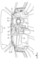
- FIG. 1 is a diagram showing a layout and the like of an information presentation system around a driver seat.
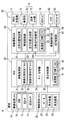
- FIG. 2 is a block diagram showing an overall image of the in-vehicle system including the HCU.
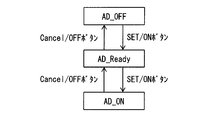
- FIG. 3 is a state transition diagram showing the transition of the operating state of the automatic driving system,
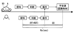
- FIG. 4 is a diagram for explaining the concept of information presentation timing and margin time,
- FIG. 5 is a flowchart showing details of the area specifying process.
- FIG. 6 is a diagram illustrating a requirement recognition range and an assumed recognition range.
- FIG. 7 is a diagram illustrating an unrecognizable area, FIG.
- FIG. 8 is a state transition diagram showing an overview of a plurality of presentation modes of the light emitting device.
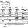
- FIG. 9 is a flowchart showing details of the mode change process for switching the presentation mode.
- FIG. 10 is a flowchart showing details of the status notification processing performed in the status notification mode.
- FIG. 11 is a flowchart showing details of the front-rear behavior presentation processing performed in the vehicle behavior mode.
- FIG. 12 is a diagram illustrating an example of a lighting width setting function for setting the lighting width of the preceding light emission spot.
- FIG. 13 is a diagram illustrating an example of a period setting function for setting a repetition period of the movement or contraction of the preceding light emission spot,
- FIG. 14 is a display example in the case where the preceding light emission spot is superimposed on the notification light emission spot.
- FIG. 15 is a flowchart showing details of the left / right behavior presentation processing performed in the vehicle behavior mode.
- FIG. 16 is a diagram illustrating an example of a position setting function for setting the lighting position of the preceding light emission spot.
- FIG. 17 is a flowchart showing details of the front-rear behavior presentation processing different from FIG.
- FIG. 18 is a diagram illustrating an example of a period setting function for setting a repetition period of movement or contraction of the preceding light emission spot.
- FIG. 19 is a flowchart showing details of the left / right behavior presentation processing different from FIG.
- FIG. 20 is a flowchart showing details of the timing setting process for setting the presentation timing of the future behavior.
- FIG. 21 is a flowchart showing details of the detail level setting process for setting the detail level of the presentation information.
- FIG. 22 is a flowchart showing details of the ability limit presentation processing performed in the action induction mode.
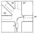
- FIG. 23 is a diagram illustrating an example of a scene in which a plurality (four) of unrecognizable areas occur.
- FIG. 24 is a diagram showing a lighting state of the light emitting device in the scene of FIG.
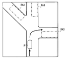
- FIG. 25 is a diagram illustrating an example of a scene in which a plurality (three) of unrecognizable areas occur.
- FIG. 26 is a diagram showing a lighting state of the light emitting device in the scene of FIG.
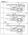
- FIG. 27 is a diagram showing a comparison of lighting modes of different preceding light emission spots for each automation level, FIG.
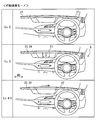
- FIG. 28 is a diagram comparing and comparing lighting modes of different induced light emission spots for each automation level
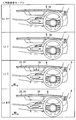
- FIG. 29 is a diagram showing a comparison of lighting states of different notification light emission spots for each automation level
- FIG. 30 is a flowchart showing details of the automation level presentation processing
- FIG. 31 is a diagram sequentially showing information presentation by the information presentation system in use case 1.
- FIG. 32 is a diagram showing the details of the behavior presentation before and after in use case 1.
- FIG. 33 is a diagram showing the details of the behavior induction presentation in use case 1.
- FIG. 34 is a diagram showing details of the behavior induction presentation by a pattern different from FIG.
- FIG. 35 is a diagram illustrating an example of a method of fading out the induced light emission spot in accordance with the driver's confirmation action
- FIG. 36 is a diagram showing information presentation in use case 2 together with FIG.
- FIG. 37 is a diagram showing information presentation in use case 2 together with FIG.
- FIG. 38 is a diagram illustrating details of the
- the function of the presentation control apparatus is realized by an HCU (HMI (Machine Machine Interface) Control Unit) 30 illustrated in FIGS. 1 and 2.
- the HCU 30 is mounted on the vehicle A together with electronic control units such as a vehicle control ECU (Electronic Control Unit) 80 and an automatic operation ECU 50.
- the vehicle control ECU 80 and the automatic driving ECU 50 are processing devices that realize an automatic driving function for performing a driving operation on behalf of the driver, and can make the vehicle A autonomously travel in cooperation.
- the HCU 30, the automatic operation ECU 50, and the vehicle control ECU 80 are electrically connected to each other directly or indirectly, and can communicate with each other.
- the vehicle control ECU 80 is directly or indirectly electrically connected to the in-vehicle sensor group 82 and the in-vehicle actuator group 83 mounted on the vehicle A.
- the in-vehicle sensor group 82 is a plurality of sensors that detect the state of the vehicle A.
- the in-vehicle sensor group 82 includes, for example, a vehicle speed sensor, a steering angle sensor, an acceleration sensor, an accelerator position sensor, and a brake pedal sensor.
- the in-vehicle actuator group 83 executes acceleration / deceleration control and operation control of the vehicle A.
- the in-vehicle actuator group 83 includes, for example, a throttle actuator of an electronically controlled throttle, an injector, a brake actuator, and a motor generator for driving and regeneration.
- the vehicle control ECU 80 is mainly configured by a computer having a processing unit, a RAM, a memory device, an input / output interface, and the like.
- the vehicle control ECU 80 executes the vehicle control program stored in the memory device by the processing unit, thereby constructing the actuator control unit 81 as a functional block related to vehicle control.
- the actuator control unit 81 integrates the in-vehicle actuator group 83 based on at least one of the operation information based on the driving operation of the driver and the autonomous traveling information acquired from the automatic driving ECU 50 and the detection information of the in-vehicle sensor group 82. Operate and control the behavior of vehicle A.
- the automatic operation ECU 50 is directly or indirectly electrically connected to a GNSS (Global Navigation Satellite System) receiver 71, a map database 72, an autonomous sensor group 73, an automatic operation switch 76, and the like.
- the automatic driving ECU 50 constructs an automatic driving system 90 in the vehicle A together with a GNSS receiver 71, a map database 72, an autonomous sensor group 73, and the like that are configured to acquire information necessary for autonomous driving.
- GNSS Global Navigation Satellite System
- the GNSS receiver 71 can receive positioning signals transmitted from a plurality of artificial satellites.
- the GNSS receiver 71 sequentially outputs the received positioning signal to the automatic operation ECU 50 as information for specifying the current position of the vehicle A.
- the map database 72 is a storage device that stores a large number of map data. Map data includes road structure information such as curvature, slope and section length of each road, building information indicating the shape of buildings around the road, and non-temporary traffic regulation information such as speed limit and one-way traffic, etc. It is included.
- the map database 72 provides map data about the current position of the vehicle A and the traveling direction to the automatic driving ECU 50 based on a request from the automatic driving ECU 50.
- the autonomous sensor group 73 detects moving objects such as pedestrians and other vehicles, and still objects such as falling objects on the road, traffic signals, guardrails, curbs, road signs, road markings, and lane markings.
- the autonomous sensor group 73 includes, for example, a camera unit, a lidar unit, a millimeter wave radar unit, and the like. Each of the autonomous sensor groups 73 sequentially outputs object information related to the detected moving object and stationary object to the automatic driving ECU 50.
- the automatic operation switch 76 is an input device that switches the operation state of the automatic operation system 90.
- the automatic operation switch 76 is provided, for example, in the spoke portion of the steering wheel 113.
- the automatic operation switch 76 includes, for example, a SET / ON button and a Cancel / OFF button.
- the automatic driving system 90 shown in FIG. 2 can perform autonomous traveling with different automation levels.
- the automation level can be set using the definition of Society of Automotive Engineers. Specifically, at the automation levels 0 to 2, the driver performs the driving operation mainly. At this time, the automatic driving system 90 is in an off state, a standby state (automated level 0), or in a state that assists the driving operation of the driver (automated levels 1 and 2). On the other hand, at the automation levels 3 to 5, the driving operation is performed mainly by the automatic driving system 90.
- the automation level as described above may be switchable by the driver, or may be automatically changed according to the automation level permitted for the travel area.
- the automatic operation ECU 50 is mainly configured by a computer having a processing unit 61, a RAM 62, a memory device 63, and an input / output interface.
- the processing unit 61 includes at least one of a CPU (Central Processing Unit), a GPU (Graphics Processing Unit), an FPGA (Field-Programmable Gate Array), and the like.
- the processing unit 61 may be provided with a dedicated accelerator specialized in AI (Artificial Intelligence) learning and inference.
- AI Artificial Intelligence
- the automatic operation ECU 50 can execute the automatic operation program stored in the memory device 63 by the processing unit 61.
- the automatic driving program includes a program for autonomously driving the vehicle A, a program for controlling driving changes between the driver and the automatic driving system 90, and the like.
- a self-vehicle position specifying unit 51, an environment recognizing unit 52, a travel plan generating unit 53, an autonomous travel control unit 54, and the like are constructed in the automatic driving ECU 50.
- the own vehicle position specifying unit 51 specifies the current position of the vehicle A based on the positioning signal received by the GNSS receiver 71.
- the own vehicle position specifying unit 51 corrects the detailed current position of the vehicle A by comparing the image of the front area acquired from the camera unit of the autonomous sensor group 73 with the detailed map data acquired from the map database 72.
- the environment recognizing unit 52 combines the position information specified by the vehicle position specifying unit 51, the map data acquired from the map database 72, the object information acquired from the autonomous sensor group 73, and the like. Recognize the driving environment.
- the environment recognizing unit 52 acquires a recognition result obtained by recognizing the shape and moving state of objects around the vehicle A based on the integration result of each object information, particularly within the detection range of each autonomous sensor.
- the environment recognition unit 52 implements the function of the periphery monitoring device 70 together with the autonomous sensor group 73.
- the environment recognition unit 52 generates a virtual space in which the actually recognized traveling environment is reproduced in three dimensions by combining the recognition result around the vehicle A, the position information, and the map data.
- a functional part including the environment recognition unit 52 and the autonomous sensor group 73 is referred to as a periphery monitoring device 70.
- the travel plan generation unit 53 generates a travel plan for causing the vehicle A to autonomously travel by the automatic driving system 90 based on the travel environment recognized by the environment recognition unit 52.
- a long-term travel plan and a short-term travel plan are generated.
- a route for directing the vehicle A to the destination set by the driver is defined.
- a planned travel route for realizing travel according to the long-term travel plan is defined using the virtual space generated by the environment recognition unit 52. Specifically, execution of lane following, steering for lane change and right / left turn, acceleration / deceleration for speed adjustment and temporary stop, and the like is determined based on a short-term travel plan.
- the autonomous traveling control unit 54 generates autonomous traveling information instructing acceleration / deceleration and steering based on the planned traveling route formulated by the traveling plan generating unit 53 in the automatic operation mode.
- the autonomous traveling control unit 54 sequentially outputs the generated autonomous traveling information to the vehicle control ECU 80.
- the autonomous traveling control unit 54 cooperates with the actuator control unit 81 to cause the vehicle A to autonomously travel along the planned traveling route.
- the HCU 30 is further connected to the occupant monitoring system 10, the information presentation system 20, and the like.
- the occupant monitoring system 10 is a system that mainly monitors the state of a driver sitting in the driver's seat 110 (see FIG. 1).
- the occupant monitoring system 10 includes a DSM (Driver Status Monitor) 11, a foot sensor 12 and a grip sensor 13.
- DSM Driver Status Monitor
- the DSM 11 includes a near-infrared light source and a near-infrared camera and a control unit for controlling them.
- the DSM 11 is arranged, for example, on the upper surface of the instrument panel in a posture with the near-infrared camera facing the driver's seat side.
- the DSM 11 photographs the upper body of the driver irradiated with near infrared light from a near infrared light source with a near infrared camera in order to monitor the driver's condition.
- the DSM 11 sequentially outputs the captured image as detection information to the HCU 30.
- the foot sensor 12 is an active object detection sensor that detects an object by light irradiation.
- the detection range of the foot sensor 12 is set so as to particularly include an accelerator pedal and a brake pedal.
- the foot sensor 12 detects the position of the driver's foot among the floor, the accelerator pedal, the brake pedal, and the like, and sequentially outputs detection information to the HCU 30.
- the grip sensor 13 is provided on the rim portion of the steering wheel 113 (see FIG. 1), and detects the grip of the steering wheel 113 by the driver.
- the grip sensor 13 sequentially outputs detection information indicating whether or not the driver is gripping the steering wheel 113 toward the HCU 30.
- the information presentation system 20 is a system that presents information related to the vehicle A to each occupant of the vehicle A including the driver.
- the information presentation system 20 includes presentation devices such as a speaker 21, a display device 22, and a light emitting device 23.
- the speaker 21 can reproduce, for example, a warning sound and a voice message.
- the display device 22 is mainly composed of a liquid crystal display, for example.
- the display device 22 is installed on the instrument panel with the display surface facing the driver's seat 110.
- the display device 22 can display various images and characters on the display screen.
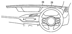
- the light-emitting device 23 is a presentation device that presents information to the occupant according to the light-emission mode of the light-emitting spot 25 that displays light in the linear stretch region 24.
- the linear extending region 24 extends linearly along the width direction WD of the vehicle A.
- a large number of light emitting elements (for example, LEDs) arranged along the width direction WD are provided in the linear extending region 24.
- the light emitting device 23 can change the number, size, position, moving direction, moving speed, light emitting color (hue, saturation, brightness), light emission luminance, and the like of the light emitting spots 25 displayed in the linear extending region 24.
- a dark dot range indicates a light-off region
- a white or very thin dot range indicates a light-emitting region where the light-emitting spot 25 is formed.
- the HCU 30 is an electronic control unit that integrally controls information presentation to the driver using the information presentation system 20.
- the HCU 30 is mainly configured by a computer having a processing unit 41, a RAM 42, a memory device 43, an input / output interface, and the like.
- the processing unit 41 includes at least one of a CPU, GPU, FPGA, and the like.
- the processing unit 41 may be provided with a dedicated accelerator specialized for AI learning and inference.
- the HCU 30 can execute the presentation control program stored in the memory device 43 by the processing unit 41.
- the presentation control program includes a program related to driver state estimation, a program related to operation control of the information presentation system 20, and the like. Based on the presentation control program, an information acquisition unit 31, a mode switching unit 34, a presentation control unit 35, and the like are constructed in the HCU 30.
- the information acquisition unit 31 acquires various information necessary for presentation using the information presentation system 20 from the occupant monitoring system 10, the automatic driving ECU 50, the vehicle control ECU 80, and the like. Specifically, the information acquisition unit 31 relates to status information of the automatic driving system 90, vehicle state information indicating the driving state of the vehicle A, driver detection information by the occupant monitoring system 10, and driving environment recognition by the periphery monitoring device 70. Acquired recognition information and the like. The information acquisition part 31 may acquire each information required for information presentation by communication, or may acquire each of these information by the process which processes the information acquired by communication.
- the status information includes, for example, information indicating the operating state of the automatic driving system 90 and information indicating the automation level of autonomous driving.
- the vehicle state information includes the speed information of the vehicle A measured using the vehicle speed sensor, the steering information of the vehicle A measured using the steering angle sensor, the information indicating the current position of the vehicle A, and the state of the surrounding traveling environment The environmental information etc. which show are included.
- the detection information is a detection result output from the DSM 11, the foot sensor 12, and the grip sensor 13.
- the recognition information includes relative position information of the object recognized by the periphery monitoring device 70, a short-term travel plan created using the recognition result, and direction information indicating the direction of the unrecognizable area RA3 (see FIG. 7). It is out.
- the information acquisition unit 31 includes an occupant state determination block 32 and a recognition state determination block 33 as sub function blocks. As described above, the occupant state determination block 32 and the recognition state determination block 33 use the information provided from the occupant monitoring system 10, the automatic driving ECU 50, and the vehicle control ECU 80 to generate information necessary for information presentation. It is.
- the occupant state determination block 32 determines the state of the driver using the detection information from the occupant monitoring system 10. Specifically, the occupant state determination block 32 relates to the driving posture, such as the driver's viewing direction, whether the steering wheel 113 and other operating systems are gripped, and whether the foot is positioned at the position where the brake pedal is stepped on. Make the decision. In addition, the occupant state determination block 32 calculates the driver's anxiety using a predetermined arithmetic expression based on the driver's facial expression, the number of blinks, hand and leg movements, and the driving posture described above. To do. For such calculation of the degree of anxiety, information such as the heart rate of the driver may be further used.
- the heart rate is measured by, for example, a wearable device worn by the driver, and transmitted to the HCU 30 by wireless communication or the like.
- Information indicating the driving posture and the degree of anxiety may be generated by the occupant monitoring system 10 and provided to the information acquisition unit 31 sequentially. In such a form, the occupant state determination block 32 can be omitted.
- the recognition state determination block 33 determines the traveling environment of the vehicle A using the recognition result by the periphery monitoring device 70. Specifically, the recognition state determination block 33 selects a risk target that is a target of alerting the occupant from the objects recognized by the periphery monitoring device 70. In addition, the recognition state determination block 33 grasps the presence of the unrecognizable area RA3 (see FIG. 6) that cannot be recognized by the periphery monitoring device 70. Note that the calculation for selecting the risk target and the calculation for grasping the unrecognizable area RA3 may be performed by the environment recognition unit 52. If both of these calculation results are provided to the information acquisition unit 31, the recognition state determination block 33 can be omitted.
- the risk target is an object whose margin time Ra for the vehicle A is negative among the objects indicated by the relative position information.
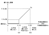
- the allowance time Ra is the minimum time necessary for responding to the object by recognizing, judging and operating the object.
- the allowance time Ra is the sum of the driver's reaction time RT and the driver's reaction delay time RDT and the time D required to respond by a braking operation or a steering operation (see FIG. 4).
- the recognition state determination block 33 calculates the margin time Ra of each recognition object based on the relative position information, and selects a recognition object having a negative value (minus) as the risk time Ra.
- the unrecognizable area RA3 is a range that becomes a capability limit of the periphery monitoring device 70, and is calculated from a difference between a sensing range necessary for autonomous traveling and a current sensing possible range.
- the recognition state determination block 33 includes a request recognition range RA1 (see FIG. 6) required by the automatic driving system 90 and an assumed recognition range RA2 (see FIG. 6) where actual recognition by the periphery monitoring device 70 is assumed.
- the unrecognizable area RA3 is set using the difference from ().
- the recognition state determination block 33 specifies the occurrence of the unrecognizable area RA3 and the direction of the unrecognizable area RA3 as viewed from the driver by area specifying processing (see FIG. 5). At least a part of the area specifying process may be executed by the environment recognition unit 52, for example.
- the area specifying process is started based on switching of the vehicle power source to the on state, and is continued until the vehicle power source is turned off.
- an assumed speed Vs (m / s) of another vehicle traveling around is acquired, and the process proceeds to S103.
- the assumed speed Vs is set to, for example, a value obtained by adding a specific value (for example, 20 km / h ⁇ 5.6 m / s) to the speed limit, or a value that can include 95% of vehicles in a normal traffic volume.
- the assumed speed Vs can be set using accumulated normal speed data. For example, 2 ⁇ ( ⁇ : standard deviation of speed) is added to the average moving speed. Set to a value.
- S103 the behavior of the host vehicle (vehicle A) after a few seconds based on the travel plan is acquired, and the process proceeds to S104.
- S104 the estimated required time T (s) related to the own vehicle behavior acquired in S103 is acquired, and the process proceeds to S105. For example, when a right turn is planned as the vehicle behavior, an estimated required time T of 6 to 7 seconds is acquired.
- the required recognition range RA1 is calculated mainly using map data. Specifically, the product of the estimated speed Vs acquired in S102 and the estimated required time T acquired in S104 with the radius of the product of the vehicle A as a center. (See FIG. 6).
- the weather information, the time zone information, the prospect information, and the like for considering the quality of the surrounding visual field are acquired as the environmental information around the vehicle A, and the process proceeds to S107.
- the line-of-sight information is information indicating the presence / absence and shape of a roadside shielding object based on map data or the like.
- the assumed recognition range RA2 is calculated using the environment information acquired in S106, and the process proceeds to S108.
- the assumed recognition range RA2 is acquired by a process of narrowing the maximum detection range of the autonomous sensor group 73 (see FIG. 2) using the environment information acquired in S106.
- the range that is the blind spot of the shielding object BO is out of the assumed recognition range RA2 (see FIG. 7).
- the unrecognizable area RA3 is fitted to the road shape shown in the map data (see FIG. 7), the unrecognizable area RA3 is set in the range where the risk target can exist, and the process proceeds to S110.
- the unrecognizable area RA3 is set on the road in a range where it becomes a blind spot from the own vehicle due to the shield BO such as a bag.
- the direction of the unrecognizable area RA3 viewed from the driver is set based on the relative position of the at least one unrecognizable area RA3 (see FIG. 7) extracted in S109.
- a plurality of directions are set (see also FIG. 23, FIG. 25, etc.).
- the information acquisition unit 31 can sequentially acquire the direction information of the unrecognizable area RA3.
- the mode switching unit 34 switches information presentation using the information presentation system 20 among a plurality of presentation modes according to the state of the vehicle A.
- the HCU 30 is preset with four presentation modes: a state notification mode, a preventive safety mode, a vehicle behavior mode, and an action induction mode.
- the state of the vehicle A that triggers the switching of the presentation mode includes the state of the vehicle A itself, the state of the vehicle A caused by the traveling environment such as whether or not a risk target is detected, and whether or not a specific operation is input.
- the state of the vehicle A caused by the driver is also included.
- the mode switching unit 34 sets the presentation mode to the vehicle behavior mode during normal autonomous driving.
- the mode switching unit 34 switches the presentation mode from the vehicle behavior mode to the preventive safety mode when a risk target occurs during autonomous traveling (Ra ⁇ 0).
- the mode switching unit 34 switches the presentation mode from the preventive safety mode to the vehicle behavior mode.
- the mode switching unit 34 switches the presentation mode from the vehicle behavior mode to the behavior induction mode.
- the mode switching unit 34 changes the presentation mode to the state notification mode. At this time, the automatic driving system 90 is in a standby state.
- the mode switching unit 34 switches from the state notification mode to the vehicle behavior mode. Transition the presentation mode.
- the mode switching unit 34 changes the presentation mode from the state notification mode to the preventive safety mode.
- the operation (start trigger) for resuming the autonomous running includes a pressing operation of the SET / ON button, a pedal operation of lightly depressing the accelerator pedal, and the like.
- the mode switching unit 34 transitions each presentation mode as described above by executing the mode change process.
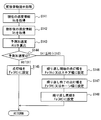
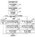
- the mode change process is started based on switching of the vehicle power source to the on state, and is continued until the vehicle power source is turned off. Details of the mode change process will be described below with reference to FIGS. 2 and 8 based on FIG.
- S121 information indicating the operating state (hereinafter, “AD state”) of the automatic driving system 90 is acquired, and the process proceeds to S122.
- AD state the operating state of the automatic driving system 90
- S122 the selection result of the risk target based on the margin time Ra (see FIG. 4) is determined. If there is a risk target whose margin time Ra is negative, the process proceeds to S123.
- S123 the presentation mode is set to the preventive safety mode, and the process returns to S121.
- the process proceeds to S124.
- S124 the AD state acquired in S121 is determined. If it is determined in S124 that the AD state is an off state or a standby state, the process proceeds to S125.
- S125 the presentation mode is set to the state notification mode, and the process returns to S121.
- the process proceeds to S126.
- S126 the presence / absence of the unrecognizable area RA3 (see FIG. 7) extracted by the recognition state determination block 33 or the like is determined. If it is determined in S126 that there is an unrecognizable area RA3, the process proceeds to S127. In S127, the presentation mode is set to the action induction mode, and the process returns to S121. On the other hand, when it is determined in S126 that there is no unrecognizable area RA3, the process proceeds to S128. In S128, the presentation mode is set to the vehicle behavior mode, and the process returns to S121.
- the presentation control unit 35 shown in FIG. 2 controls information presentation by the information presentation system 20 using the recognition information acquired by the information acquisition unit 31 and the like.
- the presentation control unit 35 has a playback control function for notification sounds and voice messages from the speaker 21, a display control function for the display device 22, and a light emission control function for the light emitting device 23.
- the light emission control function of the light emitting device 23 the light emission mode of the light emission spot 25 is changed according to the switching of the presentation mode by the mode switching unit 34, and is appropriately changed based on the latest recognition information or the like in each presentation mode.
- the presentation control unit 35 adjusts the light emission luminance of the light emission spot 25 according to the recognition reliability of the periphery monitoring device 70. Specifically, when the reliability of the driving environment recognition is reduced due to backlight, rain, dirt, or the like, the presentation control unit 35 does not reduce the reliability of the light emission luminance of the light emission spot 25. Set lower than the state. Further, the presentation control unit 35 causes the light emitting device 23 to emit light in different emission colors that are defined in advance for each presentation mode in each presentation mode set by the mode switching unit 34. Hereinafter, details of the light emission control in each presentation mode will be described in order with reference to FIGS. 2 and 8.
- the state notification mode is a presentation mode indicating the state of the automatic driving system 90, and specifically notifies the driver that the automatic driving system 90 is in an off state or a standby state.
- the state notification mode clearly indicates to the driver that the driver's operation (permission) for switching the automatic driving system 90 to the on state is necessary.
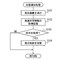
- the presentation control unit 35 performs the state notification process shown in FIG. 10 in the state notification mode.
- the state notification process is started based on switching from the action induction mode to the state notification mode.
- the light emitting device 23 is turned off, and the process proceeds to S132.
- the occupant is notified of the standby state of the automatic driving system 90.
- the start permission information is acquired, and the process proceeds to S133.
- the start permission information is information indicating an input of a start trigger for resuming autonomous travel, and is information output from the automatic driving ECU 50.
- it waits for acquisition of start permission information. If the start permission information is acquired in S133, the process proceeds to S134. In S134, switching to the light emission control of the vehicle behavior mode or the preventive safety mode is performed according to the presence or absence of the risk target, and the state notification process is terminated.
- the preventive safety mode is a presentation mode that alerts the presence of risk objects around the vehicle A.
- the presentation control unit 35 presents the relative position of the risk target around the vehicle A grasped by the recognition state determination block 33 using a light emission spot (hereinafter, “notification light emission spot 28”).
- notification light emission spot 28 For example, when there is an object that requires abrupt avoidance, the direction is indicated to the driver.
- the lighting position of the notification light emitting spot 28 is set to an intersection position where a virtual line connecting the driver's eye point and the risk target and the linear extension region 24 intersect in a top view. As described above, the notification light emission spot 28 is lit in the direction of the risk target as viewed from the driver.
- the presentation control unit 35 can guide the driver's visual recognition direction by moving the notification light emitting spot 28 in either the left or right direction where the risk target exists, for example.
- the driver can respond when the avoidance support by the automatic driving system 90 is insufficient.
- oversight of risk targets by the driver can be reduced when the automatic driving system 90 restarts.
- the light emission color of the notification light emission spot 28 is, for example, orange (amber).
- the notification light emission spot 28 can cause the occupant to foresee the occurrence of a sudden behavior than usual by lighting in a light emission color different from that of the light emission spot 25 in other presentation modes.
- the occupant of the vehicle A can be prepared in advance for a sudden change in vehicle behavior by the automatic driving system 90.
- the vehicle behavior mode is a presentation mode in which the future behavior of the autonomous traveling planned by the travel plan generation unit 53 is presented in advance by a light emitting spot (hereinafter, “preceding light emitting spot 26”).
- preceding light emitting spot 26 a light emitting spot
- the occupant of the vehicle A can acquire a clue to know the capability limit of the periphery monitoring device 70.
- the occupant of the vehicle A determines the future behavior of the object around the vehicle A. It becomes possible to foresee that the contents are missed.
- the occupant of the vehicle A can notice the misrecognition or unrecognition of the periphery monitoring device 70 using the future behavior as a clue before appearing in the vehicle behavior. Therefore, in the vehicle behavior mode, the future behavior functions as information indicating an unknown capability limit.
- the light emission color of the preceding light emission spot 26 in the vehicle behavior mode is a light emission color different from the preventive safety mode and the action induction mode, for example, green.
- the presentation control unit 35 lights the preceding light-emitting spot 26 at the lighting reference position LPr (see FIG. 8).
- the lighting reference position LPr is defined as the front position of the driver's seat 110 (see FIG. 1).
- the presentation control unit 35 performs front-rear behavior presentation, left-right behavior presentation, and the like when a behavior change from straight ahead is scheduled in the travel plan.
- the content of the animation displayed in each behavior presentation can be changed according to the planned behavior change amount or the type of behavior change.
- the presentation control unit 35 can adjust the timing and level of detail of information presentation according to the driver's state.
- the presentation control unit 35 causes the light emitting device 23 to present the front-rear behavior when the deceleration behavior is scheduled in the travel plan.
- the animation is changed according to the amount of behavior change.
- the preceding light-emitting spot 26 is lit at the lighting reference position LPr, and notifies the deceleration of the vehicle A felt by the occupant by expansion and contraction in the width direction WD.
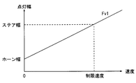
- the presentation control unit 35 changes the lighting width and period in the telescopic display of the preceding light emitting spot 26 according to the amount of change in the deceleration behavior planned in the travel plan.
- the presentation control unit 35 sets a lighting width setting function Fv1 (see FIG.
- S141 of the front / rear behavior presentation process shown in FIG. 11 the current speed information Vc is acquired, and the process proceeds to S142.
- S142 speed information Vt after a few seconds specified in the travel plan is acquired, and the process proceeds to S143.
- S143 the predicted acceleration Atd in the front-rear direction acting on the vehicle A is calculated based on the speed difference indicated by the speed information Vc and Vt acquired in S141 and S142, and the process proceeds to S144.
- the predicted acceleration Atd calculated in S143 is compared with two threshold values th1 and th2 defined in advance.
- the threshold th1 is an acceleration serving as a boundary whether or not a person feels, and is about 0.1 G, for example.
- the threshold th2 is an acceleration serving as a boundary whether or not a person becomes anxious, and is about 0.2 G, for example. If it is determined in S144 that the predicted acceleration Atd is less than the threshold th1, the process proceeds to S145.
- the lighting width of the preceding light emitting spot 26 is set using the lighting width setting function Fv1 (see FIG. 12), and the process returns to S141.
- the lighting width is defined according to the vehicle speed, and is set wider as the future speed indicated by the speed information Vt becomes higher.
- the lighting width setting function Fv1 is defined such that the lighting width corresponding to the stop (speed zero) is the horn width, and the lighting width corresponding to the speed limit of the traveling road is the steering width.
- the horn width is approximately the same as the lateral width of the center pad of the steering wheel 113.
- the steer width is approximately the same as the outer diameter of the steering wheel 113.
- the process proceeds to S146.
- the lighting width setting function Fv1 (see FIG. 12) is used to set the lighting width at the start of repetition, and the process proceeds to S147.
- the lighting width at the end of repetition is set using the lighting width setting function Fv1, and the process proceeds to S148.
- the lighting width at the start of repetition may be set to the steer width.
- the lighting width at the end of repetition may be set to the horn width.
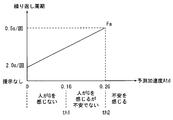
- the cycle setting function Fa (see FIG. 13) is used to set a repetition cycle of the animation for expanding and contracting the preceding light emitting spot 26, and the process returns to S141.
- the repetition period is defined according to the longitudinal acceleration, and is set shorter as the predicted acceleration Atd increases.
- the repetition period is set, for example, in a range close to a person's heart rate, and specifically, adjusted in a range of 0.5 to 2.0 (seconds / time).
- the animation expression of the preceding light spot 26 becomes larger as the vehicle speed and acceleration are larger and the uneasiness of the passenger is more likely to increase. Therefore, the occupant can intuitively understand the future movement of the vehicle A and the steepness of the behavior change. In addition, when the vehicle speed and acceleration are small and anxiety of the occupant is suppressed, the animation expression of the preceding light emission spot 26 becomes small. As a result, the occupant's troublesomeness can be reduced.
- the presentation mode is switched from the vehicle behavior mode to the preventive safety mode.
- the presentation control unit 35 causes the light-emitting device 23 to display the preceding light-emitting spot 26 on the notification light-emitting spot 28 (see FIG. 14). From the viewpoint of the driver, the preceding light emission spot 26 is superposed on the notification light emission spot 28. The size (horizontal width) of the notification light emission spot 28 is larger than the size of the preceding light emission spot 26. The preceding light spot 26 is turned off after showing the future behavior of the vehicle A.
- the presentation control unit 35 causes the light emitting device 23 to present the left-right behavior when a behavior accompanied by left-right movement (hereinafter, “left-right behavior”) is scheduled in the travel plan.
- the animation is changed according to the amount of behavior change.
- the preceding light emitting spot 26 gives a notice of the lateral movement of the vehicle A felt by the occupant by displaying repeatedly moving left or right. For example, when a left turn of the vehicle A, a lane change to the left lane, a merge in the left direction, and the like are scheduled, the preceding light emitting spot 26 repeats a movement flowing in the left direction. Similarly, when a right turn of the vehicle A, a lane change to the right lane, a merge in the right direction, and the like are scheduled, the preceding light emission spot 26 repeats a movement flowing in the right direction.
- the presentation control part 35 changes the movement width and period in the horizontal movement display of the prior
- the presentation control unit 35 sets a position setting function Fv2 (see FIG. 16) for defining the lighting mode of the preceding light emitting spot 26 and a cycle setting function Fa (see FIG. 12) for defining the cycle of movement.
- Fv2 see FIG. 16
- a cycle setting function Fa for defining the cycle of movement.
- S151 of the left / right behavior presentation process shown in FIG. 15 the current steering information Sc is acquired, and the process proceeds to S152.
- S152 the steering information St after a few seconds specified in the travel plan is acquired, and the process proceeds to S153.
- S153 the predicted lateral acceleration Ats in the left-right direction acting on the vehicle A is calculated based on the steering angle difference indicated by the steering information Sc and St acquired in S151 and S152, and the process proceeds to S154.
- the predicted lateral acceleration Ats calculated in S153 is compared with two threshold values th1 and th2 defined in advance.
- the threshold values th1 and th2 may be the same as the values used in the front / rear behavior presentation process. If it is determined in S154 that the predicted lateral acceleration Ats is less than the threshold th1, the process proceeds to S155.
- the lighting position of the preceding light-emitting spot 26 is set using the position setting function Fv2 (see FIG. 16), and the process returns to S151.
- the lighting position is defined according to the steering angle, and is set at a position away from the lighting reference position LPr in either the left or right steering direction as the future steering angle indicated by the steering information St increases.
- the steering angle is 90 ° or more
- the preceding light emitting spot 26 apparently coincides with the left end or the right end of the steering wheel 113 at a position ( ⁇ steer width) separated from the lighting reference position LPr by the radius of the steering wheel 113. Is displayed.
- the process proceeds to S156.
- the position setting function Fv2 (see FIG. 16) is used to set the lighting position for repeated start, and the process proceeds to S157.
- the position setting function Fv2 is used to set the lighting position at the end of repetition, and the process proceeds to S158.
- the lighting position at the start of repetition may be set to the lighting reference position LPr. Further, the lighting position at the end of repetition may be set to a position of ⁇ steer width.
- the cycle setting function Fa (see FIG. 13) is used to set an animation repetition period for moving the preceding light-emitting spot 26, and the process returns to S151.
- the repetition cycle is defined according to the lateral acceleration, and is set shorter as the predicted lateral acceleration Ats increases.
- the repetition cycle of the left / right behavior presentation is adjusted in the range of 0.5 to 2.0 (seconds / times), similarly to the front / rear behavior presentation.
- the animation expression of the preceding light-emitting spot 26 becomes larger as the steering angle and the change in the steering angle are larger and the passenger's anxiety is more likely to increase. Therefore, the occupant can intuitively understand the future movement of the vehicle A and the steepness of the behavior change. In addition, when the steering angle and the steering angle change are small and anxiety of the occupant is suppressed, the animation expression of the preceding light spot 26 becomes small. As a result, the occupant's troublesomeness can be reduced.
- the presentation control unit 35 changes the animation mode using the preceding light emission spot 26 as another display pattern for presenting the front-rear behavior according to the type of deceleration behavior planned in the travel plan.
- the presentation control unit 35 displays an animation when the signal is scheduled to pass through and an animation when the signal is scheduled to stop in a different manner.
- the presentation control unit 35 defines the lighting width and period in the expansion / contraction display of the preceding light emitting spot 26 based on the lighting width setting function Fv1 (see FIG. 12) and the period setting function Fa (see FIG. 18). To do.
- Fv1 see FIG. 12
- Fa period setting function
- the speed information Vc, Vt after the current and several seconds later and the predicted acceleration Atd in the front-rear direction are obtained by substantially the same process as S141-S143 (see FIG. 11). And the process proceeds to S164.
- S164 the type of future behavior scheduled in the travel plan is determined. If it is determined in S164 that the vehicle stops at a signal, specifically, a temporary stop, a red light stop, a stop for waiting for a right turn, a stop following the preceding vehicle, etc., the process proceeds to S166. .
- the lighting width at the start of repetition, the lighting width at the end of repetition, and the repetition period are set to the lighting width setting function Fv1 (see FIG. 12) and the period setting by substantially the same processing as S146 to S148 (see FIG. 11). It sets using the function Fa (refer FIG. 18).
- the animation for contracting the preceding light emission spot 26 toward the lighting reference position LPr is repeatedly displayed.
- the process proceeds to S169.
- the lighting width at the start of repetition is set to the horn width, and the process proceeds to S170.
- a lighting width at the end of repetition is set using a lighting width setting function Fv1 (see FIG. 12), and the process proceeds to S171.
- the lighting width at the end of repetition set in S170 may be a steer width.
- the repetition cycle of expansion and contraction of the preceding light-emitting spot 26 is set using the cycle setting function Fa (see FIG. 18). As described above, the animation for expanding the preceding light emitting spot 26 to the outside is repeatedly displayed in the signal passing schedule presentation.
- the process proceeds to S165.
- the lighting width of the preceding light-emitting spot 26 is set by substantially the same processing as S145 (see FIG. 11), and the process returns to S161. In this case, the preceding light emission spot 26 having a lighting width corresponding to the speed after deceleration is displayed at the lighting reference position LPr.
- the presentation control unit 35 changes the mode of animation using the preceding light-emitting spot 26 as another display pattern for presenting the left-right behavior according to the type of left-right behavior planned in the travel plan. Even in the presentation of left and right behavior, if the classification of future behavior is presented in detail, the passenger can easily understand the future behavior. As an example, the presentation control unit 35 displays a left-right behavior animation for maintaining traveling in a lane and a left-right movement animation across the lane in different modes. Even in such another pattern, the presentation control unit 35 defines the movement width and period in the lateral movement display of the preceding light emitting spot 26 based on the position setting function Fv2 (see FIG. 16) and the period setting function Fa (see FIG. 18). To do. The details of another left / right behavior presentation process for changing the mode of animation according to the type of planned left / right behavior will be described below.
- the process proceeds to S186.
- the position setting function Fv2 (see FIG. 16) is used to set the lighting position for repeated start, and the process proceeds to S187.
- the position setting function Fv2 is used to set the lighting position at the end of repetition, and the process proceeds to S188.
- S188 based on the predicted lateral acceleration Ats calculated in S183, a repetition period for moving the preceding light emitting spot 26 is set using the period setting function Fa (see FIG.
- the lighting position at the start of repetition may be set to the lighting reference position LPr. Further, the lighting position at the end of repetition may be set to ⁇ steer width.
- the presentation control unit 35 can change the timing of the advance presentation according to the driver's state.
- the presentation control unit 35 uses the calculation result of the margin time Ra (see FIG. 4) in the recognition state determination block 33 to adjust the timing of the previous presentation to a time when the occupant does not feel uneasy.
- the presentation control unit 35 presents the recognition and determination in the automatic driving system 90 at the same timing as the driver's recognition and determination (see FIG. 4).
- the advance presentation timing is set to a time when the margin time Ra is about 0 to 2 seconds, and is adjusted according to the driving posture and the anxiety level of the driver. According to such setting, even when the recognition and determination in the automatic driving system 90 are wrong, the driver can respond without anxiety.
- the details of the timing setting process for setting the timing of prior presentation will be described below.
- S191 of the timing setting process shown in FIG. 20 information related to the driving posture determined in the occupant state determination block 32 is acquired, and the process proceeds to S192.
- S192 the current driving posture of the driver is diagnosed based on the information acquired in S191. If it is determined in S192 that the driver's hand is holding the steering wheel 113 and the driver's foot is stepping on the brake pedal, the process proceeds to S193. In S193, since the driver is in the correct driving posture, the driver's reaction delay time RDT (see FIG. 4) is set to zero, and the process proceeds to S197.
- the process proceeds to S194.
- the driver's reaction delay time RDT is set to 0.5 seconds, and the process proceeds to S197.
- the process proceeds to S195.
- the driver's reaction delay time RDT is set to 1.0 second, and the process proceeds to S197.
- the process proceeds to S196.
- the driver's reaction delay time RDT is set to 2.0 seconds, and the process proceeds to S197.
- S197 the driver's anxiety degree calculated in the occupant state determination block 32 is acquired, and the process proceeds to S198.
- the degree of anxiety acquired in S197 is determined. If it is determined in S198 that the degree of anxiety is low, the process proceeds to S199.
- S199 the time when the margin time Ra becomes zero is set as the presentation timing.
- the process proceeds to S200, and the time when the margin time Ra is 1.0 second is set as the presentation timing. If it is determined in S198 that the degree of anxiety is high, the process proceeds to S201, and the time when the margin time Ra is 2.0 seconds is set as the presentation timing. As a result of the above processing, the higher the degree of anxiety, the earlier the timing of prior presentation with respect to the arrival time at the source of anxiety.
- the presentation control unit 35 can adjust the level of detail of information presentation according to the driver's state (anxiety level).
- the presentation control unit 35 causes the information presentation system 20 to present more detailed information when the driver's anxiety level is higher and higher.
- the presentation control unit 35 stops the summary presentation when the driver's sense of security is high or higher. According to the adjustment of the information granularity according to the degree of anxiety, it is possible to ensure both a sense of security and a reduction in bothersomeness.
- the details of the detail level setting process for setting the detail level of information presentation will be described below.
- the driver's anxiety level calculated in the occupant state determination block 32 is acquired, and the process proceeds to S212.
- S212 the degree of anxiety acquired in S211 is determined. If it is determined in S212 that the degree of anxiety is low, the process proceeds to S213.
- the display device used for information presentation in the information presentation system 20 is set to the display device 22 and the light emitting device 23.
- the information presentation in this case is a content that shows an outline of the future behavior, and is intended to realize monitoring by the driver and understanding of the instantaneous information in parallel with the peripheral monitoring.
- the process proceeds to S214.
- S214 in addition to the display device 22 and the light emitting device 23, the speaker 21 is set as a presentation device to be used. In this case, the passenger 21 is notified of the content of the future behavior by the speaker 21. Furthermore, if it is determined in S212 that the degree of anxiety is high, the process proceeds to S215. In S215, as in S214, the light emitting device 23, the display device 22, and the speaker 21 are set to be used. In this case, in addition to the contents of the future behavior, the reason for the behavior change is notified to the occupant by at least one of display and sound. According to such information presentation, the driver can confirm the details of the behavior change as necessary.
- the behavior induction mode is a presentation mode that notifies the occurrence of the unrecognizable area RA3 (see FIG. 7) and prompts the driver to perform confirmation action or driving change of the unrecognizable area RA3.
- the unrecognizable area RA3 is an area indicating the capability limit of the periphery monitoring device 70, and is an area where the automatic driving system 90 cannot grasp the situation.
- the unknown ability limit is presented indirectly, whereas in the behavior induction mode, the known ability limit is presented directly. Since the capability limit of the peripheral monitoring device 70 is known in advance and it becomes easy to understand which direction should be confirmed, the driver can cope with the capability limit with a margin.
- the presentation control unit 35 presents the presence of the unrecognizable area RA3 (see FIG. 7) grasped by the recognition state determination block 33 using a light emission spot (hereinafter referred to as “guided light emission spot 27”, see FIG. 8).
- the light emission color of the induced light emission spot 27 in the behavior induction mode is a light emission color different from that in the preventive safety mode in order to prevent confusion with the case where there is a risk target, for example, yellow.
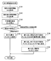
- the induced light spot 27 indicates the direction of the unrecognizable area RA3 as viewed from the driver. Details of the capability limit presentation processing for controlling the presentation of the unrecognizable area RA3 will be described below with reference to FIG. 22 and FIGS. 23 to 26 together with FIG.
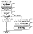
- the direction information (see S110 in FIG. 5) of the unrecognizable area RA3 grasped by the recognition state determination block 33 is acquired, and the process proceeds to S302.
- the number of directions in the current unrecognizable area RA3 is determined from the direction information acquired in S301.
- the lighting pattern is changed according to the number of occurrences of the capacity limit. If the number of directions is zero in S302, that is, if there is no unrecognizable area RA3, the process returns to S301.
- the process proceeds to S303.
- the lighting position of the induced light emission spot 27 (see FIG. 8) is set in the direction of the unrecognizable area RA3, and the process proceeds to S304.
- S304 between the lighting positions set in S304, it is set as a light-off state, and the process proceeds to S307.
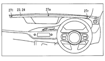
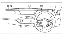
- S302 when it is determined that the number of directions of the unrecognizable area RA3 is three or more (see FIGS. 23 and 25), the process proceeds to S305. In this case, all the two directions indicating the outermost unrecognizable area RA3 are turned on. In S305, both end positions of the light emission range 27a are defined. Specifically, in S305, among the directions of the plurality of unrecognizable areas RA3, a position 27r that is the right end as viewed from the driver and a position 27l that is the left end are set, and the process proceeds to S306 (see FIGS. 24 and 26). In S306, the lighting state is set between the two lighting positions set in S305, and the process proceeds to S307. According to the band-like light emission in the light emission range 27a, it is possible to prevent the occupant from being confused due to the lighting of the many induced light emission spots 27.
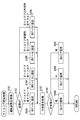
- S307 information indicating the viewing direction of the driver specified in the occupant state determination block 32 (hereinafter, “viewing direction information”) is acquired, and the process proceeds to S308.
- viewing direction information information indicating the viewing direction of the driver specified in the occupant state determination block 32
- the guide light emission spot 27 is moved from the lighting reference position LPr in front of the driver's seat 110 to the lighting position set in S303 or S305, and the process proceeds to S310.
- the guided light emission spot 27 is repeatedly moved for a specific time or a specific number of times, and the process proceeds to S313.
- the process proceeds to S311.
- S311 in the top view, the guide light emission spot 27 is moved from the intersection position where the imaginary line defining the line-of-sight direction and the linear extension region 24 (see FIG. 24) intersect to the lighting position set in S303 or S305. Move to S312.
- S312 after repeating the movement of the induced light emission spot 27 for a specific time or a specific number of times, the process proceeds to S313.
- Each presentation mode described so far is based on the premise of automatic operation at automation level 2.
- the presentation control unit 35 illuminates the light emission mode of the light emission spot 25 in each presentation mode, specifically, the lighting reference position LPr and the lighting according to the automation level of automatic driving.
- the width can be changed.
- information presentation that mainly targets the driver is performed as the personal mode.
- the automation level is 3 or higher, information presentation for all passengers is performed as the all-person mode.
- the lighting reference position LPr of the preceding light emission spot 26 is set in front of the driver's seat 110 (see FIG. 1).
- the lighting reference position LPr is set closer to the center of the vehicle A than the front position of the driver's seat 110, and is set to the center of the vehicle A in the width direction WD as an example.
- the lighting width of the preceding light-emitting spot 26 is a specific width X defined in advance. And the preceding light emission spot 26 notifies future behavior by the change of a lighting width and a lighting position. By such presentation, the future behavior of the vehicle A is transmitted to the passengers other than the driver.
- the lighting width of the preceding light emission spot 26 is extended to the entire linear extending region 24. Thereby, the whole linear extending
- the light emitting device 23 presents that the driver does not need to respond by not changing the expression according to the future behavior.
- the induced light spot 27 presents the direction of the unrecognizable area RA3 (see FIG. 23) in which the capability of the periphery monitoring device 70 is insufficient, to the driver. Request supplementary verification capabilities.
- the light emitting device 23 requests the driver to change driving by light emission of the linear extending region 24. Specifically, in the case of the automation level 3, several seconds to several minutes before the driving change is required, the guide light emission spot 27 having a specific width X is lit in the center of the vehicle A in the width direction WD.
- the lighting width of the induced light emission spot 27 is expanded to the entire linear extending region 24 several seconds to several minutes before the driving change is required. Thereby, the whole linear extending
- the notification light emitting spot 28 presents the direction of the risk target to the driver.
- the notification light emission spot 28 presents the direction of the risk target to the driver.
- the notification light emission spot 28 in the case of the automation level 2 plays a role of notifying the occurrence of sudden braking or sudden steering, or prompting an override by the driver.
- the notification light emission spot 28 is lit with the specific width X in the center of the width direction WD in the vehicle A regardless of the direction of the risk target.
- the lighting width of the notification light emission spot 28 is expanded to the entire linear stretch region 24, and the entire linear stretch region 24 emits light.
- the light emitted from the light-emitting device 23 is a presentation for notifying all passengers of the occurrence of sudden braking or sudden steering by the automatic driving system 90.
- the presentation control unit 35 changes the setting of each presentation mode according to the automation level.
- the light emitting device 23 can present the current automation level from the light emission mode of the linearly extending region 24 (see FIG. 29, etc.).
- details of the automation level presentation processing performed by the presentation control unit 35 will be described.
- S401 of the automation level presentation process shown in FIG. 30 information indicating the automation level of the automatic operation being operated in the automatic operation system 90 is acquired, and the process proceeds to S402.
- the automation level acquired in S401 is determined. If it is determined in S401 that the automation level is 0 (manual operation) or 1, the process proceeds to S403.
- the vehicle behavior mode is set to the off state, and the process proceeds to S404.
- the action induction mode is set to the off state, and the process proceeds to S405.
- the lighting reference position LPr is set in front of the driver's seat 110, and the process proceeds to S406.
- the reference lighting width is set to the specific width X, and the process ends.
- the process proceeds to S407.
- the vehicle behavior mode is set to the on state, and the process proceeds to S408.
- the action induction mode is set to the on state, and the process proceeds to S409.
- the lighting reference position LPr is set in front of the driver, and the process proceeds to S410.
- the reference lighting width is set to the specific width X, and the process ends.
- the process proceeds to S411.
- the vehicle behavior mode is set to the on state, and the process proceeds to S412.
- the action induction mode is set to the on state, and the process proceeds to S413.
- the lighting reference position LPr is set at the center of the vehicle A, and the process proceeds to S414.
- the reference lighting width is set to the specific width X, and the process ends.
- the process proceeds to S415.
- the vehicle behavior mode is set to the on state, and the process proceeds to S416.
- the action induction mode is set to the on state, and the process proceeds to S417.
- the lighting reference position LPr is set at the center of the vehicle A, and the process proceeds to S418.
- the lighting width is set to the entire surface of the linear extension region 24 (see FIG. 29), and the process ends.
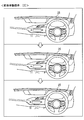
- the vehicle A in which the automatic driving system 90 is on travels straight by autonomous traveling and approaches the intersection (see [1] in FIG. 31).
- the light-emitting device 23 is presenting information in the vehicle behavior mode, and lights the preceding light-emitting spot 26 at the lighting reference position LPr.
- an icon indicating a traffic sign indicating a temporary stop is displayed on the display device 22.
- the speaker 21 (see FIG. 2) utters a voice message “There will be a pause for the future”.
- the light emitting device 23 uses the preceding light emitting spot 26 to notify the start of deceleration. Specifically, the light emitting device 23 repeatedly displays an animation for contracting the preceding light emitting spot 26 inward (see [2] in FIG. 31 and FIG. 32). Then, when the automatic driving system 90 stops the vehicle A before the stop line, the preceding light-emitting spot 26 is turned on in a state of being reduced to, for example, the horn width (see FIG. 12) (see [3] in FIG. 31). . When a two-stage stop at the intersection is performed, information presentation [1] to [3] in FIG. 31 is repeated.
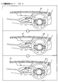
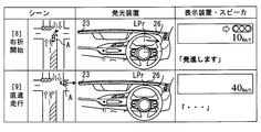
- the presentation mode of the light emitting device 23 transitions from the vehicle behavior mode to the action induction mode.
- the light emitting device 23 prompts the driver to confirm the status of the unrecognizable area RA3 by the induced light emission spot 27 (see [4] in FIG. 31).
- the display device 22 displays an overhead view of the intersection indicating the position of the unrecognizable area RA3 and a message for prompting safety confirmation and permission to start.
- a voice message “Please check the surrounding safety and press the start button” is uttered from the speaker 21 (see FIG. 2).
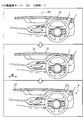
- the light-emitting device 23 splits the induced light-emitting spot 27 lit at the lighting reference position LPr left and right in [4] in FIG. 31, and moves it to the direction of the unrecognizable area RA3.
- the DSM 11 detects the driver's visual recognition direction, as shown in FIG. 34, the induced light emission spot 27 is split left and right after moving from the lighting reference position LPr toward the gazing point PG. Also good.
- the light emitting device 23 fades out the induced light spot 27 after repeating the movement of the guided light spot 27 a plurality of times (see [5] in FIG. 31).
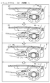
- the induced light emission spots 27 are sequentially turned off based on the situation confirmation of the unrecognizable area RA3 by the driver.
- FIG. 35 when the driver's gazing point PG is directed to the unrecognizable area RA3 that is in the right direction when viewed from the driver, the right direction light emitting spot 27 is turned off.
- the left guide light emission spot 27 is turned off.
- the guide light emission spot 27 is turned off after a lapse of a certain time from the start of lighting.
- the presentation mode transitions from the behavior induction mode to the state notification mode in accordance with the timing when the information presentation in the behavior induction mode is completed and the induced light emission spot 27 is turned off.
- the automatic driving system 90 enters a standby state waiting for the driver's operation to be permitted to start.
- the automatic driving system 90 transitions to an on state.
- the presentation mode of the light emitting device 23 also transitions from the state notification mode to the vehicle behavior mode.
- the light emitting device 23 repeatedly displays an animation for moving the preceding light emitting spot 26 to the right from the lighting reference position LPr (see [6] in FIG. 31).
- the autonomous running is resumed.
- the vehicle A transitions to straight running due to the completion of the right turn the preceding light emission spot 26 is turned on at the lighting reference position LPr (see [7] in FIG. 31).
- Vehicle A in which the automatic driving system 90 is in an on state travels straight by autonomous traveling and approaches an intersection of green lights (see [1] in FIG. 36).
- the light emitting device 23 is presenting information in the vehicle behavior mode, and lights the preceding light emitting spot 26 at the lighting reference position LPr.
- the speaker 21 (see FIG. 2) utters a voice message saying “I will turn right at the intersection.
- the right direction indicator starts blinking.
- the light emitting device 23 will give notice of deceleration. Specifically, an animation for contracting the preceding light emitting spot 26 is displayed on the light emitting device 23 to the lighting width corresponding to the vehicle speed after several seconds set in the travel plan (see [2] in FIG. 36).
- the automatic driving system 90 causes the vehicle A, which has been slowly decelerated, to enter the right turn lane. A few seconds before entering the right turn lane, the light emitting device 23 repeatedly displays an animation for moving the preceding light emitting spot 26 to the right from the lighting reference position LPr (see [3]).
- the movement width of the preceding light-emitting spot 26 in the right direction is a movement width corresponding to the steering amount after several seconds set in the travel plan.
- the light-emitting device 23 When the vehicle A stops at the intersection, the light-emitting device 23 lights the preceding light-emitting spot 26 at the lighting reference position LPr with a lighting width corresponding to when the vehicle is stopped (0 km / h) (see [4] in FIG. 36). . When the vehicle A stops due to a red light, the light-emitting device 23 changes to the state [4] without repeating the information [3] after repeating [1] and [2] in FIG. 36. To do.
- the light-emitting device 23 When the unrecognizable area RA3 has occurred in the vicinity of the intersection, the light-emitting device 23 presents information in the behavior induction mode, and prompts the driver to confirm the status of the unrecognizable area RA3 by the induced light emission spot 27 ( (See [5] in FIG. 36). Specifically, the light-emitting device 23 splits the induced light-emitting spot 27 lit at the lighting reference position LPr to the left and right, and moves a part thereof to the position of the unrecognizable area RA3 in the right direction (see FIG. 38). At this time, the display device 22 displays an overhead view of the intersection indicating the position of the unrecognizable area RA3 and a message for prompting safety confirmation and permission to start. In addition, a voice message “Please check the surrounding safety and press the start button” is uttered from the speaker 21 (see FIG. 2).
- the light emitting device 23 repeats the movement of the induced light emission spot 27 a plurality of times, and then fades out the induced light emission spot 27 (see [6] in FIG. 36).
- the guided light emission spots 27 are sequentially turned off based on the confirmation action of the unrecognizable area RA3 by the driver.
- the guide light emission spot 27 is turned off after a lapse of a certain time from the start of lighting.
- the presentation mode transitions from the behavior induction mode to the state notification mode at the timing when the action induction presentation in the action induction mode is completed and the induced light emission spot 27 is turned off.
- the automatic driving system 90 holds the start permission by the driver at the timing when the oncoming vehicle is detected as a risk target, and maintains the stop state of the vehicle A.
- the presentation mode of the light emitting device 23 transitions from the state notification mode to the preventive safety mode.
- the notification light emission spot 28 is turned on in the direction of the oncoming vehicle that is the risk target (see [7] in FIG. 36).
- a voice message “Waiting for the oncoming vehicle to pass” is uttered from the speaker 21 (see FIG. 2).
- the vehicle A When the risk target disappears due to the passing of the oncoming vehicle intersection, the vehicle A starts making a right turn at the intersection. At this time, the presentation mode of the light-emitting device 23 transitions from the preventive safety mode to the vehicle behavior mode as the risk is eliminated. As a result, an animation for moving the preceding light emission spot 26 from the lighting reference position LPr to the right is repeatedly displayed (see [8] in FIG. 37). After the information presentation by the movement of the preceding light emitting spot 26 and the utterance of the voice message “I will start”, the autonomous running is resumed. Then, when the vehicle A goes straight ahead upon completion of the right turn, the preceding light emission spot 26 is turned on at the lighting reference position LPr (see [9] in FIG. 37).
- the capability limit of the peripheral monitoring device 70 is controlled by the light emission control of the light emitting device 23 implemented in each presentation mode.
- the occupant of the vehicle A can obtain a clue to know the capability limit of the periphery monitoring device 70 on many occasions. Therefore, the HCU 30 can reduce the anxiety of the occupant about the driving environment recognition in the vehicle A.
- the driver can almost always recognize the clue to know the capacity limit, so that the vehicle A can be aware of misrecognition and unrecognition in the recognition of the driving environment while the risk level of the vehicle A is low. .
- the driver can supplement the automatic driving system 90 and cope with the risk. If such a response is possible, the driver's sense of security with respect to automatic driving is less likely to be impaired.
- the presentation mode is switched based on the presence / absence of the unrecognizable area RA3 indicating the capability limit of the periphery monitoring device 70. According to such transition of the presentation mode, it is possible to perform information presentation that prompts the driver to perform an action that complements the capacity limit after the automatic driving system 90 self-detects the occurrence of the capacity limit.
- display is performed in which the preceding light emission spot 26 is superimposed on the notification light emission spot 28 due to the occurrence of a risk target.
- Such information presentation makes it easier for the passenger to grasp the situation. As a result, the occupant can calmly cope with a sudden behavior change by the automatic driving system 90 for dealing with the risk target.
- the relative position of the unrecognizable area RA3 is presented according to the direction of the guide light emission spot 27 viewed from the driver.
- the occupant can easily grasp the generation range of the capability limit of the automatic driving system 90 and can smoothly complement the capability limit. Therefore, even if the capacity limit occurs, an increase in passenger anxiety is unlikely to occur.
- the induced light emission spot 27 in the present embodiment moves toward the unrecognizable area RA3. According to such presentation, it is possible to induce the driver to visually recognize the unrecognizable area RA3. As described above, if the occupant's supplementary behavior is promoted by the behavior of the induced light spot 27, the anxiety of the occupant to the vehicle A displaying the induced light spot 27 can be reduced.
- the light emitting device 23 can transmit the existence of a large number of unrecognizable areas RA3 to the occupant without omission while avoiding a situation in which the occupant is confused by the light emission of the large number of induced light spots 27.
- the automatic driving system 90 stops autonomous traveling and enters a standby state. Therefore, if the state is changed to the state notification mode indicating the standby state in accordance with the extinction of the guide light emission spot, the suspension of the autonomous traveling is clearly shown to the driver who has confirmed the unrecognizable area RA3. As a result, the driver is prompted to input an operation that permits the resumption of autonomous driving.
- the lighting reference position LPr is switched according to the automation level of autonomous driving. Such switching makes it easier for the occupant to grasp the automation level. And according to the state grasp of the automation level, the anxiety of the occupant to the automatic driving system 90 is further reduced.
- the unrecognizable area RA3 is set based on the difference between the required recognition range RA1 and the assumed recognition range RA2. According to such processing, the unrecognizable area RA3 can be appropriately set within a range that is a capability limit of the periphery monitoring device 70 and needs to be supplemented by the driver. Therefore, a situation in which the driver's load for supplementing the automatic driving system 90 and the periphery monitoring device 70 is unnecessarily increased is avoided.
- the light emission colors of the light emission spots 25 in each presentation mode are different from each other. Therefore, even if the presentation mode is switched among a plurality, the light emitting device 23 can present to the occupant without confusing the state of the automatic driving system 90. As a result, the passenger's sense of security can be further improved.
- the light emitting device 23 corresponds to the “light emitting unit”
- the positions 27r and 27l correspond to “both end positions”
- the presentation control unit 35 corresponds to the “light emitting control unit”
- the HCU 30 It corresponds to a “presentation control device”.
- the capability limit of the peripheral monitoring device was presented.
- the number of presentation modes set in the HCU is not limited to four, and may be five or more, for example.
- the number of presentation modes for presenting capability limits may be three or more.
- the presentation mode for presenting the capability limit may be all or a part of a plurality of preset presentation modes.
- information serving as a trigger for switching each presentation mode is not limited to the presence or absence of an unrecognizable area as in the above embodiment. Various information related to the state of the vehicle can be used as trigger information for changing the presentation mode.
- the future behavior presentation in the vehicle behavior mode and the direction presentation of the unrecognizable area in the behavior induction mode correspond to presentation of the capability limit, respectively.
- the method of presenting the capability limit in each presentation mode may be changed as appropriate.
- the content of the animation using the light emission spot in the vehicle behavior mode and the behavior induction mode may be changed as appropriate.
- the directions of the individual unrecognizable areas may be presented individually by lighting a large number of induced light emission spots.
- the emission colors defined for each presentation mode may not be all different. That is, the emission colors defined in some presentation modes may be substantially the same. When the two emission colors are set differently, it is desirable that these emission colors are separated by a predetermined angle or more on the hue circle.
- the configuration of the light emitting device for displaying the light emitting spots can be changed as appropriate.
- a linear extending region that displays a movable light emitting spot may be realized by using a self-luminous panel such as an organic EL formed in a band shape.
- the installation position of the light emitting device can be changed as appropriate.
- the light emitting device may be installed above the windshield in a shape along the upper edge of the windshield.
- the light emitting device may be installed below the windshield and project light onto the lower edge region of the windshield. In this configuration, each passenger sees the reflected light reflected by the lower edge region of the windshield. That is, the light emitting device may be a virtual image display device that allows a passenger to visually recognize a virtual image of a light emitting spot.
- an automatic driving system capable of changing the automation level of autonomous driving has been assumed.
- the automation level of autonomous driving realized by the automatic driving system may not be changeable.
- the automatic driving system is a system that performs only autonomous level 2 or 3 autonomous traveling, and may be a system that does not perform autonomous level 4 or higher autonomous traveling. Even if it is such a form, the change of the light emission mode of the light-emitting device according to an automation level may not be implemented.
- the definition of the automation level is not limited to the above definition and can be changed as appropriate.
- the function provided by the control circuit of the HCU can be provided by hardware and software different from those described above, or a combination thereof.
- Various non-transitory physical storage media can be employed for the memory device 63 (see FIG. 1) that stores the presentation control program.
- the storage medium for storing the presentation control program is not limited to the memory device of the HCU, and may be an optical disk serving as a copy source to the memory device, a hard disk drive of a general-purpose computer, or the like.
- each unit is expressed as, for example, S101.
- each part can be divided into a plurality of sub-parts, while the plurality of parts can be combined into one part.
- each part configured in this manner can be referred to as a circuit, a device, a module, and a means.
- each of the plurality of parts described above or a combination thereof includes not only (i) a software part combined with a hardware unit (for example, a computer) but also (ii) hardware (for example, an integrated circuit, As a part of the (wiring logic circuit), it can be realized with or without including the functions of related devices.
- the hardware unit can be configured inside a microcomputer.
Landscapes
- Engineering & Computer Science (AREA)
- Transportation (AREA)
- Mechanical Engineering (AREA)
- Combustion & Propulsion (AREA)
- Chemical & Material Sciences (AREA)
- Automation & Control Theory (AREA)
- Remote Sensing (AREA)
- Radar, Positioning & Navigation (AREA)
- General Physics & Mathematics (AREA)
- Physics & Mathematics (AREA)
- Human Computer Interaction (AREA)
- Traffic Control Systems (AREA)
- Navigation (AREA)
- Control Of Driving Devices And Active Controlling Of Vehicle (AREA)
- Instrument Panels (AREA)
Applications Claiming Priority (2)
| Application Number | Priority Date | Filing Date | Title |
|---|---|---|---|
| JP2018021189A JP6911786B2 (ja) | 2018-02-08 | 2018-02-08 | 提示制御装置、及び提示制御プログラム |
| JP2018-021189 | 2018-02-08 |
Publications (1)
| Publication Number | Publication Date |
|---|---|
| WO2019155824A1 true WO2019155824A1 (ja) | 2019-08-15 |
Family
ID=67549526
Family Applications (1)
| Application Number | Title | Priority Date | Filing Date |
|---|---|---|---|
| PCT/JP2019/000806 Ceased WO2019155824A1 (ja) | 2018-02-08 | 2019-01-14 | 提示制御装置、及び提示制御プログラム |
Country Status (2)
| Country | Link |
|---|---|
| JP (1) | JP6911786B2 (enExample) |
| WO (1) | WO2019155824A1 (enExample) |
Cited By (3)
| Publication number | Priority date | Publication date | Assignee | Title |
|---|---|---|---|---|
| EP3995340A1 (en) * | 2020-11-10 | 2022-05-11 | Toyota Jidosha Kabushiki Kaisha | Vehicle display control device, acceleration display method, and non-transitory memory medium memorizing program |
| US20220284717A1 (en) * | 2019-12-02 | 2022-09-08 | Denso Corporation | Consciousness determination device and consciousness determination method |
| CN116142221A (zh) * | 2021-11-22 | 2023-05-23 | 本田技研工业株式会社 | 车辆 |
Families Citing this family (9)
| Publication number | Priority date | Publication date | Assignee | Title |
|---|---|---|---|---|
| JP7200968B2 (ja) * | 2020-03-31 | 2023-01-10 | トヨタ自動車株式会社 | 車両制御装置および車両制御方法 |
| JP7297166B2 (ja) * | 2020-09-25 | 2023-06-23 | 三菱電機株式会社 | 移動体制御装置および移動体制御方法 |
| JP7558071B2 (ja) * | 2021-01-18 | 2024-09-30 | 株式会社東海理化電機製作所 | 発光装置、制御装置および移動体 |
| WO2022158230A1 (ja) * | 2021-01-21 | 2022-07-28 | 株式会社デンソー | 提示制御装置及び提示制御プログラム |
| WO2023281959A1 (ja) * | 2021-07-05 | 2023-01-12 | 株式会社デンソー | 提示制御装置、提示制御プログラム、自動運転制御装置、及び自動運転制御プログラム |
| JP7626095B2 (ja) * | 2021-07-05 | 2025-02-04 | 株式会社デンソー | 提示制御装置、提示制御プログラム、自動運転制御装置、及び自動運転制御プログラム |
| JP2023112364A (ja) * | 2022-02-01 | 2023-08-14 | 株式会社小糸製作所 | 制御装置 |
| JP7567849B2 (ja) * | 2022-03-31 | 2024-10-16 | トヨタ自動車株式会社 | 発光制御装置、発光装置、車両、発光制御方法及び発光制御プログラム |
| WO2024181081A1 (ja) * | 2023-03-02 | 2024-09-06 | 株式会社デンソー | 車両用制御装置及び車両用制御方法 |
Citations (2)
| Publication number | Priority date | Publication date | Assignee | Title |
|---|---|---|---|---|
| JP2007233770A (ja) * | 2006-03-01 | 2007-09-13 | Alpine Electronics Inc | 車載周辺状況提示装置 |
| JP2016196289A (ja) * | 2015-04-03 | 2016-11-24 | 株式会社デンソー | 情報提示装置 |
-
2018
- 2018-02-08 JP JP2018021189A patent/JP6911786B2/ja active Active
-
2019
- 2019-01-14 WO PCT/JP2019/000806 patent/WO2019155824A1/ja not_active Ceased
Patent Citations (2)
| Publication number | Priority date | Publication date | Assignee | Title |
|---|---|---|---|---|
| JP2007233770A (ja) * | 2006-03-01 | 2007-09-13 | Alpine Electronics Inc | 車載周辺状況提示装置 |
| JP2016196289A (ja) * | 2015-04-03 | 2016-11-24 | 株式会社デンソー | 情報提示装置 |
Cited By (4)
| Publication number | Priority date | Publication date | Assignee | Title |
|---|---|---|---|---|
| US20220284717A1 (en) * | 2019-12-02 | 2022-09-08 | Denso Corporation | Consciousness determination device and consciousness determination method |
| EP3995340A1 (en) * | 2020-11-10 | 2022-05-11 | Toyota Jidosha Kabushiki Kaisha | Vehicle display control device, acceleration display method, and non-transitory memory medium memorizing program |
| US11794581B2 (en) | 2020-11-10 | 2023-10-24 | Toyota Jidosha Kabushiki Kaisha | Vehicle display control device, acceleration display method, and non-transitory memory medium memorizing program |
| CN116142221A (zh) * | 2021-11-22 | 2023-05-23 | 本田技研工业株式会社 | 车辆 |
Also Published As
| Publication number | Publication date |
|---|---|
| JP6911786B2 (ja) | 2021-07-28 |
| JP2019137179A (ja) | 2019-08-22 |
Similar Documents
| Publication | Publication Date | Title |
|---|---|---|
| JP6911786B2 (ja) | 提示制御装置、及び提示制御プログラム | |
| US11267480B2 (en) | Travel control apparatus and travel control method | |
| JP7249914B2 (ja) | 走行制御装置及び車載システム | |
| JP6814153B2 (ja) | 車両用照明装置、車両システム及び車両 | |
| US10392027B2 (en) | Driving assistance control apparatus | |
| CN107000760B (zh) | 车辆控制设备、车辆控制方法和程序 | |
| KR101730321B1 (ko) | 운전자 보조 장치 및 그 제어방법 | |
| US10723367B2 (en) | Information presentation device and information presentation method | |
| CN108883724B (zh) | 驾驶辅助方法、装置、驾驶控制装置、车辆和记录介质 | |
| CN107408349B (zh) | 信息提示装置以及信息提示方法 | |
| JP6761426B2 (ja) | 車両用照明装置、車両システム及び車両 | |
| JP6489084B2 (ja) | 自動運転システム | |
| JP6587650B2 (ja) | 自動運転時情報伝達方法および車載情報提示装置 | |
| CN107428299A (zh) | 信息提示装置 | |
| KR20170093817A (ko) | 자동 운전 제어 디바이스 및 자동 운전 제어 방법, 및 프로그램 | |
| JP7198142B2 (ja) | 車両制御システム | |
| JP2020164038A (ja) | 車両制御システム | |
| JP2018181269A (ja) | 提示制御装置、自動運転制御装置、提示制御方法及び自動運転制御方法 | |
| JP2020164085A (ja) | 車両制御システム | |
| JP2020164081A (ja) | 車両制御システム | |
| CN112590809A (zh) | 车载界面装置和车辆 | |
| JP2020163986A (ja) | 車両制御システム | |
| CN116490414A (zh) | 用于根据前方车辆运行驾驶功能的车辆引导系统和方法 | |
| WO2019166102A1 (en) | Driver attention system | |
| US20250303962A1 (en) | Notification method, notification system, and vehicle |
Legal Events
| Date | Code | Title | Description |
|---|---|---|---|
| 121 | Ep: the epo has been informed by wipo that ep was designated in this application |
Ref document number: 19751850 Country of ref document: EP Kind code of ref document: A1 |
|
| NENP | Non-entry into the national phase |
Ref country code: DE |
|
| 122 | Ep: pct application non-entry in european phase |
Ref document number: 19751850 Country of ref document: EP Kind code of ref document: A1 |