WO2019150894A1 - メッシュ及びコンクリート剥落防止材 - Google Patents
メッシュ及びコンクリート剥落防止材 Download PDFInfo
- Publication number
- WO2019150894A1 WO2019150894A1 PCT/JP2019/000334 JP2019000334W WO2019150894A1 WO 2019150894 A1 WO2019150894 A1 WO 2019150894A1 JP 2019000334 W JP2019000334 W JP 2019000334W WO 2019150894 A1 WO2019150894 A1 WO 2019150894A1
- Authority
- WO
- WIPO (PCT)
- Prior art keywords
- fiber bundle
- glass fiber
- mesh
- synthetic fiber
- synthetic
- Prior art date
- Legal status (The legal status is an assumption and is not a legal conclusion. Google has not performed a legal analysis and makes no representation as to the accuracy of the status listed.)
- Ceased
Links
Images




Classifications
-
- D—TEXTILES; PAPER
- D03—WEAVING
- D03D—WOVEN FABRICS; METHODS OF WEAVING; LOOMS
- D03D15/00—Woven fabrics characterised by the material, structure or properties of the fibres, filaments, yarns, threads or other warp or weft elements used
- D03D15/20—Woven fabrics characterised by the material, structure or properties of the fibres, filaments, yarns, threads or other warp or weft elements used characterised by the material of the fibres or filaments constituting the yarns or threads
- D03D15/283—Woven fabrics characterised by the material, structure or properties of the fibres, filaments, yarns, threads or other warp or weft elements used characterised by the material of the fibres or filaments constituting the yarns or threads synthetic polymer-based, e.g. polyamide or polyester fibres
-
- C—CHEMISTRY; METALLURGY
- C04—CEMENTS; CONCRETE; ARTIFICIAL STONE; CERAMICS; REFRACTORIES
- C04B—LIME, MAGNESIA; SLAG; CEMENTS; COMPOSITIONS THEREOF, e.g. MORTARS, CONCRETE OR LIKE BUILDING MATERIALS; ARTIFICIAL STONE; CERAMICS; REFRACTORIES; TREATMENT OF NATURAL STONE
- C04B14/00—Use of inorganic materials as fillers, e.g. pigments, for mortars, concrete or artificial stone; Treatment of inorganic materials specially adapted to enhance their filling properties in mortars, concrete or artificial stone
- C04B14/38—Fibrous materials; Whiskers
- C04B14/42—Glass
-
- C—CHEMISTRY; METALLURGY
- C04—CEMENTS; CONCRETE; ARTIFICIAL STONE; CERAMICS; REFRACTORIES
- C04B—LIME, MAGNESIA; SLAG; CEMENTS; COMPOSITIONS THEREOF, e.g. MORTARS, CONCRETE OR LIKE BUILDING MATERIALS; ARTIFICIAL STONE; CERAMICS; REFRACTORIES; TREATMENT OF NATURAL STONE
- C04B16/00—Use of organic materials as fillers, e.g. pigments, for mortars, concrete or artificial stone; Treatment of organic materials specially adapted to enhance their filling properties in mortars, concrete or artificial stone
- C04B16/04—Macromolecular compounds
- C04B16/06—Macromolecular compounds fibrous
-
- C—CHEMISTRY; METALLURGY
- C04—CEMENTS; CONCRETE; ARTIFICIAL STONE; CERAMICS; REFRACTORIES
- C04B—LIME, MAGNESIA; SLAG; CEMENTS; COMPOSITIONS THEREOF, e.g. MORTARS, CONCRETE OR LIKE BUILDING MATERIALS; ARTIFICIAL STONE; CERAMICS; REFRACTORIES; TREATMENT OF NATURAL STONE
- C04B41/00—After-treatment of mortars, concrete, artificial stone or ceramics; Treatment of natural stone
- C04B41/60—After-treatment of mortars, concrete, artificial stone or ceramics; Treatment of natural stone of only artificial stone
-
- D—TEXTILES; PAPER
- D03—WEAVING
- D03D—WOVEN FABRICS; METHODS OF WEAVING; LOOMS
- D03D1/00—Woven fabrics designed to make specified articles
-
- D—TEXTILES; PAPER
- D03—WEAVING
- D03D—WOVEN FABRICS; METHODS OF WEAVING; LOOMS
- D03D15/00—Woven fabrics characterised by the material, structure or properties of the fibres, filaments, yarns, threads or other warp or weft elements used
-
- D—TEXTILES; PAPER
- D03—WEAVING
- D03D—WOVEN FABRICS; METHODS OF WEAVING; LOOMS
- D03D15/00—Woven fabrics characterised by the material, structure or properties of the fibres, filaments, yarns, threads or other warp or weft elements used
- D03D15/50—Woven fabrics characterised by the material, structure or properties of the fibres, filaments, yarns, threads or other warp or weft elements used characterised by the properties of the yarns or threads
- D03D15/587—Woven fabrics characterised by the material, structure or properties of the fibres, filaments, yarns, threads or other warp or weft elements used characterised by the properties of the yarns or threads adhesive; fusible
-
- D—TEXTILES; PAPER
- D03—WEAVING
- D03D—WOVEN FABRICS; METHODS OF WEAVING; LOOMS
- D03D9/00—Open-work fabrics
Definitions
- the present invention relates to a mesh and a concrete exfoliation preventing material provided with the mesh.
- a method of sticking a reinforcing material to the surface of a concrete frame is known as a measure for preventing the peeling of the concrete frame such as a building or a tunnel.
- a reinforcing material an anti-peeling material in which a mesh such as glass fiber or synthetic resin is embedded in cement mortar or resin is used.
- Patent Document 1 discloses a mesh used as a reinforcing material for a concrete frame.
- the mesh of Patent Document 1 is a mesh fabric in which a main fiber bundle composed of a plurality of strands is woven.
- the mesh fabric has an auxiliary fiber bundle entangled with a main fiber bundle, and is configured by impregnating the auxiliary fiber bundle with a resin.
- a mesh fabric is produced by entwining a cotton fiber, which is an auxiliary fiber bundle, with a glass fiber bundle, which is a main fiber bundle, and an acrylic resin is applied to the obtained mesh fabric by an immersion method. An impregnated mesh fabric is described.
- both the load and displacement in the punching test which is an index of the concrete peeling prevention property, may not be sufficiently increased.
- both the load and displacement in the punching test cannot be sufficiently increased, the reinforcing effect of the concrete frame may not be sufficiently obtained.
- cracks may occur in the concrete frame with a small load, or the cracked concrete pieces may fall off immediately. Therefore, peeling of concrete may not be sufficiently prevented.
- An object of the present invention is to provide a mesh having excellent punching characteristics that is an index of concrete peeling prevention characteristics, and a concrete peeling prevention material using the mesh.
- the mesh according to the present invention is a mesh composed of fiber bundles extending in a plurality of directions, and includes a glass fiber bundle and a synthetic fiber bundle having a tensile strength of 2000 MPa or more, and the glass A volume ratio of the glass fiber bundle to a sum of volumes of the fiber bundle and the synthetic fiber bundle is 20% or more and 95% or less.
- the tensile strength in the above is calculated
- the tensile elongation of the synthetic fiber bundle measured according to JIS L1015 (2010) is preferably 2% or more and 10% or less.
- the basis weight is preferably 100 g / m 2 or more and 900 g / m 2 or less.
- the mesh according to the present invention is preferably composed of a plurality of warps and a plurality of wefts.
- At least one of the warp and the weft includes both the glass fiber bundle and the synthetic fiber bundle.
- the warp yarn and the weft yarn include both the glass fiber bundle and the synthetic fiber bundle, respectively, and a ratio between the number of the synthetic fiber bundles and the number of the glass fiber bundles in the warp yarn ( Synthetic fiber bundle) / (glass fiber bundle) is 0.5 or more and 2.0 or less, and the ratio of the number of the synthetic fiber bundles to the number of the glass fiber bundles in the weft yarn (synthetic fiber bundle) / ( The glass fiber bundle) is preferably 0.5 or more and 2.0 or less.
- the glass fiber bundle preferably has a plurality of glass fiber monofilaments and a coating covering the surface of the glass fiber monofilament.
- the glass fiber monofilament preferably has an average diameter of 10 ⁇ m or more and 30 ⁇ m or less.
- the loss on ignition of the glass fiber bundle after being immersed in a styrene monomer at 25 ° C. for 1 hour is 20% or more lower than the loss on ignition of the glass fiber bundle before immersion. preferable.
- the coating contains a silane coupling agent.
- the glass fiber bundle and the synthetic fiber bundle are preferably sealed with heat-sealing yarns.
- the mesh according to the present invention is preferably used as a concrete exfoliation preventing material.
- the concrete exfoliation preventing material according to the present invention is characterized by comprising a matrix and a mesh configured according to the present invention.
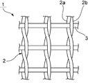
- FIG. 1 is a schematic plan view showing a mesh according to the first embodiment of the present invention.
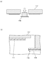
- Fig.2 (a) is typical sectional drawing for demonstrating a behavior when a punching test is done using the mesh which concerns on the 1st Embodiment of this invention.
- FIG.2 (b) is typical sectional drawing which expands and shows the part in which the mesh is provided in Fig.2 (a).
- FIG. 3A is a schematic cross-sectional view for explaining the behavior when a punching test is performed using a mesh made of only a synthetic fiber bundle as a comparative example.
- FIG.3 (b) is typical sectional drawing which expands and shows the part in which the mesh is provided in Fig.3 (a).
- FIG. 4A is a schematic cross-sectional view for explaining the behavior when a punching test is performed using a mesh made of only a glass fiber bundle as a comparative example.
- FIG.4 (b) is a schematic diagram which expands and shows the part in which the mesh is provided in Fig.4 (a).
- FIG. 5 is a schematic plan view showing a mesh according to the second embodiment of the present invention.
- FIG. 6 is a schematic cross-sectional view showing a concrete exfoliation preventing material according to an embodiment of the present invention.
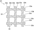
- FIG. 7 is a schematic plan view showing the meshes obtained in Examples 1, 2, 5 to 11.
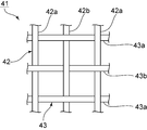
- FIG. 8 is a schematic plan view showing the meshes obtained in Examples 3, 4, and 12.
- FIG. 1 is a schematic plan view showing a mesh according to the first embodiment of the present invention.
- the mesh 1 is a mesh fabric in which a plurality of warps 2 and a plurality of wefts 3 are woven. Accordingly, the mesh 1 is composed of a plurality of warp yarns 2 and a plurality of weft yarns 3.
- the plurality of warps 2 each have a first strand 2a and a second strand 2b.
- the first strand 2a and the second strand 2b are entangled with each other so as to be twisted, and a plurality of wefts 3 are woven between them. That is, the mesh 1 is a woven fabric in which the first strand 2a and the second strand 2b constituting the warp yarn 2 and the weft yarn 3 are woven together.
- the first strand 2a constituting the warp yarn 2 is constituted by one glass fiber bundle.
- the second strand 2b constituting the warp yarn 2 is constituted by one synthetic fiber bundle.
- the 1st strand 2a may be comprised by the several glass fiber bundle
- the 2nd strand 2b may be comprised by the several synthetic fiber bundle.
- the 1st strand 2a is comprised with the glass fiber bundle and the synthetic fiber bundle
- the 2nd strand 2b may be comprised with the glass fiber bundle and the synthetic fiber bundle.
- the warp yarn 2 in which the first strand 2a and the second strand 2b are constituted by a synthetic fiber bundle, and the warp yarn 2 in which the first strand 2a and the second strand 2b are constituted by a glass fiber bundle are used. It may be used.
- the plurality of weft yarns 3 are preferably each composed of a twisted yarn obtained by twisting a glass fiber bundle and a synthetic fiber bundle.
- the weft yarn 3 may not be a twisted yarn, and may be a non-twisted yarn in which a glass fiber bundle and a synthetic fiber bundle are bundled without being twisted.
- the plurality of weft threads 3 may be composed only of glass fiber bundles, or may be composed only of synthetic fiber bundles. Among them, it is preferable to prepare two types of weft yarns 3 made of glass fiber bundles and weft yarns 3 made of synthetic fiber bundles, and these two types of weft yarns 3 are alternately arranged along the direction in which the warp yarn 2 extends. . In this case, the distribution of the glass fiber bundle and the synthetic fiber bundle in the mesh 1 can be made even more uniform.
- the warp yarn 2 and the weft yarn 3 are each composed of both a glass fiber bundle and a synthetic fiber bundle.
- the mesh 1 should just contain the glass fiber bundle and the synthetic fiber bundle.
- At least one of the warp yarn 2 and the weft yarn 3 includes both a glass fiber bundle and a synthetic fiber bundle. More preferably, the warp yarn 2 and the weft yarn 3 each include both a glass fiber bundle and a synthetic fiber bundle.
- the tensile strength of the synthetic fiber bundle constituting the mesh 1 is 2000 MPa or more.
- the tensile strength of the synthetic fiber bundle can be measured in accordance with JIS L1015 (2010).
- the unit of tensile strength in this embodiment is MPa, whereas the unit of tensile strength in JIS L1015 (2010) is N / tex.
- the unit can be converted by dividing the tensile strength in JIS L1015 (2010) by the specific gravity of the synthetic fiber constituting the synthetic fiber bundle.
- the tensile strength of the synthetic fiber bundle is preferably 2500 MPa or more, more preferably 3000 MPa or more, preferably 5000 MPa or less, more preferably 4000 MPa or less.
- the load can be further increased in the punching test.
- the tensile strength of the synthetic fiber bundle is not more than the above upper limit value, the displacement can be further increased in the punching test.
- the volume ratio of the glass fiber bundle to the sum of the volume of the glass fiber bundle and the synthetic fiber bundle (the volume of the glass fiber bundle / the sum of the volumes of the glass fiber bundle and the synthetic fiber bundle) is 20% or more and 95%. It is as follows. In addition, when deposits, such as coating resin, have adhered to the mesh 1, the volume of deposits is not taken into consideration.
- the mesh 1 includes the synthetic fiber bundle having the specific tensile strength, and the volume ratio of the glass fiber bundle is within the specific range. A sufficient load and displacement can be obtained in the punching test.
- the ratio of the number of synthetic fiber bundles to the number of glass fiber bundles in the warp yarn 2 (synthetic fiber bundle) / ( The glass fiber bundle) is preferably 0.5 or more and 2.0 or less, more preferably 0.8 or more and 1.2 or less.
- the ratio (synthetic fiber bundle) / (glass fiber bundle) between the number of synthetic fiber bundles and the number of glass fiber bundles in the weft 3 is preferably 0.5 or more and 2.0 or less, more preferably. 0.8 or more and 1.2 or less.
- the sheet 6 is composed of a mesh 1 and a matrix resin 8 as shown in FIG.
- the sheet 6 is obtained by impregnating the mesh 1 with the matrix resin 8.
- the mesh 1 includes a synthetic fiber bundle having high tensile strength
- the tensile strength of the sheet 6 is high.
- the sheet 6 can withstand the shearing stress at the time of punching. That is, the punching load is high. In particular, as shown in FIG. 2A, the punching load after the sheet 6 is partially peeled from the concrete housing 7 increases.
- the glass fiber bundle is excellent in adhesiveness with the matrix resin 8.
- the shear stress at the time of punching becomes larger than the adhesive force of the sheet 6 to the concrete housing 7, a part of the sheet 6 is peeled from the concrete housing 7 as shown in FIG. Since the adhesive force between the glass fiber bundle and the matrix resin 8 is large, the glass fiber bundle does not slip through the matrix resin 8 even when the sheet 6 is peeled off, and the glass fiber bundle is bonded to the matrix resin 8. Therefore, even after a part of the sheet 6 is peeled from the concrete housing 7, the sheet 6 can maintain the tensile strength, so that the punching displacement can be increased. Therefore, in the sheet 6 using the mesh 1, a high punching load and displacement can be obtained.
- FIGS. 3 (a) and 3 (b) show the behavior when a sheet 106 using a mesh 101 made only of a synthetic fiber bundle is attached to a concrete case 107 and a punch test is performed as a comparative example. ing.
- the sheet 106 includes a mesh 101 and a matrix resin 108.
- the matrix resin 108 is bonded to the concrete housing 107, but has a low adhesive force to the mesh 101. Therefore, as shown in FIG. 3 (a), when a part of the sheet 106 is peeled off from the concrete casing 107 due to the shear stress at the time of punching, the mesh 101 slips out of the matrix resin 108 as shown in FIG. 3 (b). . When the mesh 101 slips through, the tensile strength of the sheet 106 decreases, and the punching load cannot be sufficiently increased. Further, since the tensile strength of the sheet 106 is lowered, a sufficient punching displacement cannot be obtained.
- FIG. 4 (a) and (b) as a comparative example, the behavior when a sheet 116 using a mesh 111 made of only glass fiber bundles is attached to a concrete case 117 and a punching test is performed is shown. ing. As shown in FIG. 4B, the sheet 116 includes a mesh 111 and a matrix resin 118.
- the tensile strength of the sheet 6 is increased by using the mesh 1 including the glass fiber bundle excellent in adhesiveness with the matrix resin 8 and the synthetic fiber bundle having high tensile strength. And is excellent in adhesiveness with the matrix resin 8. As a result, even if the sheet 6 peels while withstanding the shear stress at the time of punching, the tensile strength can be maintained, so that a high punching load and displacement can be obtained.
- the volume ratio of the glass fiber bundle to the sum of the volumes of the glass fiber bundle and the synthetic fiber bundle is less than 20%, the adhesiveness between the mesh 1 and the matrix resin 8 is low, and the mesh 1 slips out of the matrix resin 8. . Further, when the volume ratio of the glass fiber bundle exceeds 95%, the mesh 1 is broken.
- the mesh 1 has a volume ratio of the glass fiber bundle of 20% or more and 95% or less, a sufficient load and displacement can be reliably obtained in the punching test.
- the volume ratio of the glass fiber bundle to the sum of the volumes of the glass fiber bundle and the synthetic fiber bundle is preferably 25% or more, preferably 85% or less, and more Preferably it is 50% or more, preferably 80% or less.
- the basis weight of the mesh 1 is not particularly limited, but is preferably 100 g / m 2 or more, more preferably 150 g / m 2 or more, preferably 900 g / m 2 or less, more preferably 700 g / m 2 or less.
- the basis weight of the mesh 1 is not less than the above lower limit value, the rigidity of the mesh 1 can be further increased.
- the basis weight of the mesh 1 is not more than the above upper limit value, the mesh interval of the mesh 1 is sufficiently secured, and the impregnation property of the matrix resin 8 can be further enhanced. Therefore, the adhesiveness between the mesh 1 and the matrix resin 8 can be further enhanced.
- the mesh 1 of this embodiment can obtain sufficient load and displacement in the punching test that is an index of the concrete peeling prevention characteristic, the reinforcing effect of the concrete frame can be enhanced, and the concrete peeling prevention use Can be suitably used.
- the glass fiber bundle includes a plurality of glass fiber monofilaments and a coating covering the surface of the glass fiber monofilament.
- the glass fiber bundle constituting the warp yarn 2 and the weft yarn 3 includes, for example, a bundle of a plurality of glass fiber monofilaments of about several tens to several hundreds.
- a plurality of glass fiber monofilaments are focused by applying a sizing agent to the surface.
- a film is formed by drying the sizing agent.
- Each of the glass fiber monofilaments constituting the glass fiber bundle preferably contains 12% by mass or more of ZrO 2 as a glass composition.
- ZrO 2 a glass composition
- the alkali resistance can be further improved. Therefore, it is difficult for the mesh 1 to be eroded by the alkali component present in the cement, and the deterioration of the mesh 1 can be further suppressed.
- R 2 O (R is at least one selected from Li, Na and K) is contained in an amount of 10% by mass or more, even if ZrO 2 is contained in an amount of 12% by mass or more, the meltability is further improved. Can be. Note that the R 2 O is 10 wt% or more, Li 2 O in the glass fiber monofilaments in, the total content of Na 2 O and K 2 O, refers to at least 10 mass%.
- a glass fiber monofilament for example, as a glass composition, by mass%, SiO 2 54 to 65%, ZrO 2 12 to 25%, Li 2 O 0 to 5%, Na 2 O 10 to 17%, K 2 O 0-8%, R′O (where R ′ represents Mg, Ca, Sr, Ba, Zn) 0-10%, TiO 2 0-10%, Al 2 O 3 0-2% Including, preferably by mass%, SiO 2 57-64%, ZrO 2 14-24%, Li 2 O 0-3%, Na 2 O 10-17%, K 2 O 0-5%, R′O (However, R ′ represents Mg, Ca, Sr, Ba, and Zn.)
- a material containing 0.2 to 8%, TiO 2 0.5 to 9%, and Al 2 O 3 0 to 1% should be used. it can.
- the glass fiber monofilament containing 12% by mass or more of ZrO 2 preferably has a tensile strength of 500 to 1700 MPa in view of manufacturing cost and strength.
- the average diameter of the glass fiber monofilament is preferably 10 ⁇ m or more and 30 ⁇ m or less, more preferably 10 ⁇ m or more and 20 ⁇ m or less.
- the productivity can be further enhanced.
- the average diameter of the glass fiber monofilament is not more than the above upper limit value, the surface area can be further increased and the adhesion with the matrix resin 8 can be further enhanced. Further, in the punching test, the glass fiber bundle can be made more difficult to break.
- polyester resin examples include polyester resin.
- the polyester resin may be a saturated polyester resin or an unsaturated polyester resin.
- vinyl acetate resin and urethane resin may be used. These may be used alone or in combination.
- the coating further contains a silane coupling agent.
- the silane coupling agent include amino silane, epoxy silane, vinyl silane, acrylic silane, chloro silane, mercapto silane, and ureido silane.
- the adhesiveness of a glass fiber bundle and the matrix resin 8 can be improved further by adding a silane coupling agent.
- the coating preferably has high hydrophobicity.
- the coating can contain components such as a lubricant, a nonionic surfactant, and an antistatic agent. To decide.
- the ignition loss after being immersed in a styrene monomer at 25 ° C. for 1 hour is 20% or more lower than the ignition loss before immersion.
- a glass fiber bundle with a known loss on ignition is prepared.
- the loss on ignition is a value measured by the method described in JIS R3420 (2013).
- 20 g of this glass fiber bundle is immersed in 1000 ml of styrene monomer at 25 ° C. for 1 hour.
- the glass fiber bundle is pulled up and dried at 25 ° C. for 24 hours.
- the loss on ignition of the dried glass fiber bundle is measured by the method described in JIS R3420.
- the ignition loss after immersion in the styrene monomer thus measured is preferably 20% or more lower than the ignition loss before immersion. In this case, the adhesiveness between the glass fiber bundle and the matrix resin 8 can be further enhanced.
- the coating is formed by applying a sizing agent to the surface of the glass fiber monofilament and drying it. Accordingly, the coating and the sizing agent contain the same components.
- the count of the glass fiber bundle is not particularly limited, but is preferably 100 tex or more and 3000 tex or less. When the count of the glass fiber bundle is within the above range, the load and displacement can be further increased in the mesh 1 push-out test.
- the synthetic fiber bundle constituting the warp yarn 2 and the weft yarn 3 is a bundling body of a plurality of synthetic fiber monofilaments. But the synthetic fiber bundle may be comprised by one synthetic fiber.
- the synthetic fiber bundle preferably has a tensile elongation measured in accordance with JIS L1015 (2010) of 2% or more and 10% or less.
- the tensile elongation of the synthetic fiber bundle is in the above range, the tensile elongation of the synthetic fiber bundle is close to the tensile elongation of the glass fiber bundle. It is even closer to the behavior of Therefore, the mesh 1 is stressed more evenly with respect to the external stress, and both the tensile strength and the adhesiveness of the mesh 1 can be further enhanced.
- the synthetic fiber bundle extends in the same manner as the glass fiber bundle, and as a result, higher tensile strength can be imparted to the sheet 6.
- the tensile elongation is more preferably 3% or more and 7% or less.
- the synthetic fiber bundle is not particularly limited, and examples thereof include a carbon fiber bundle, an aramid fiber bundle, and a polyethylene fiber bundle. These may be used alone or in combination.
- the fiber bundles constituting the warp yarn 2 and the weft yarn 3 are preferably the same type of synthetic fiber bundles, but may be different types of synthetic fiber bundles.
- the count of the synthetic fiber bundle is not particularly limited, but is preferably 20 tex or more and 1000 tex or less. When the count of the synthetic fiber bundle is within the above range, the load and displacement can be further increased in the punching test.
- the glass raw material put in the glass melting furnace is melted to form molten glass, and after the molten glass is made into a homogeneous state, the molten glass is drawn out from a heat-resistant nozzle attached to the bushing. Thereafter, the drawn molten glass is cooled to form a glass fiber monofilament (glass fiber).
- a sizing agent for forming a film is applied to the surface of the glass fiber.
- the sizing agent is evenly applied, several hundred to several thousand glass fibers are drawn and bundled and dried to obtain a glass fiber bundle.
- the obtained glass fiber bundle is used as the first strand 2a, and the warp yarn 2 is formed by entanglement with the synthetic fiber bundle as the second strand 2b prepared in advance. Further, the weft yarn 3 is formed by twisting a separately prepared glass fiber bundle and a separately prepared synthetic fiber bundle by the above method. By weaving the weft yarn 3 into the warp yarn 2, a mesh 1 which is a woven fabric woven by entanglement weaving can be obtained.
- the mesh 1 may be further covered with a coating resin.
- a coating resin material such as an acrylic resin, an unsaturated polyester resin, or a vinyl ester resin is applied to the mesh 1 by a dipping method or a spray method, and a crossing portion of the warp yarn 2 and the weft yarn 3 is processed to be sealed.
- the form of the resin raw material may be either a resin emulsion or a solvent-based resin.
- the resin applied to the mesh 1 is dried.
- the mesh 1 may be pressed with a pair of squeeze rollers, for example, and resin applied excessively may be squeezed out.
- the resin emulsion when used, water is evaporated at a temperature of 100 to 120 ° C., and in the case of a solvent-based resin, the main purpose is to dry the contained solvent, so that excessive curing is not promoted. It is preferable to dry at a temperature of 40 to 80 ° C.
- the heating temperature in the case of thermocompression bonding is 100 degreeC or more and 200 degrees C or less. When the heating temperature is equal to or higher than the lower limit, the sealing strength can be further increased.
- FIG. 5 is a schematic plan view showing a mesh according to the second embodiment of the present invention.
- the mesh 21 is configured by plain weaving of the warp yarn 4 and the weft yarn 5.
- the warp yarn 4 is composed of a glass fiber bundle 4a and a synthetic fiber bundle 4b.
- the glass fiber bundle 4a and the synthetic fiber bundle 4b are alternately arranged in the direction in which the weft 5 extends.
- the weft 5 is comprised by the glass fiber bundle 5a and the synthetic fiber bundle 5b.
- the glass fiber bundles 5a and the synthetic fiber bundles 5b are alternately arranged in the direction in which the warp yarn 4 extends. Other points are the same as in the first embodiment.
- the mesh 21 of the second embodiment also includes a synthetic fiber bundle having a specific tensile strength, and the volume ratio of the glass fiber bundle is within the specific range. Both displacements can be obtained.
- the mesh 21 is excellent in the punching characteristic which becomes an index of the concrete peeling prevention characteristic, the reinforcing effect of the concrete frame can be enhanced and can be suitably used for concrete peeling prevention.
- the mesh of the present invention is not limited to the entangled weave and the plain weave as in the first embodiment and the second embodiment, and a pattern-woven fabric can also be used.
- the mesh of the present invention may be a braided fabric, and the method for creating the mesh is not particularly limited. Further, it may be biaxial or may be multiaxial with three or more axes. However, it is preferable that both the glass fiber bundle and the synthetic fiber bundle are arranged equally in the coaxial direction, and it is preferable that both the glass fiber bundle and the synthetic fiber bundle are arranged on each axis.
- FIG. 6 is a schematic cross-sectional view showing a concrete exfoliation preventing material according to an embodiment of the present invention.
- the concrete exfoliation preventing material 10 includes a mesh 1 and a matrix 12.
- the mesh 1 is the mesh of the first embodiment described above.
- the mesh 1 is embedded in the matrix 12.
- the concrete peeling prevention material 10 can be affixed and used for the concrete frame 13, for example.
- the mesh 1 excellent in the punching property is embedded in the matrix 12
- the reinforcing effect of the concrete can be enhanced, and the concrete peeling can be effectively prevented. Can do.
- the material of the matrix 12 is not particularly limited, and for example, a matrix resin can be used like the matrix resin 8 used in the first embodiment.
- a matrix resin can be used like the matrix resin 8 used in the first embodiment.
- the matrix resin include an epoxy resin, a urethane resin, an acrylic resin, a phenol resin, and a polyester resin. These may be used alone or in combination.
- the matrix may not be a resin, and may be an inorganic material made of, for example, a cement-based binder.
- the glass fiber bundle has good adhesiveness with calcium silicate crystals generated from the hydration reaction of the cement-based binder. Even in this case, since the mesh 1 is provided, the reinforcing effect of the concrete can be enhanced, and it can be suitably used as a concrete reinforcing material.
- a sizing agent in which vinyl silane, a saturated polyester resin, and a lubricant are dispersed in water is adjusted on the surface of the obtained glass fiber monofilament with an applicator so that the loss on ignition is 0.8% by mass. After coating and bundling the glass fibers, the sizing agent was dried to produce a glass fiber bundle.
- a mesh 31 shown in FIG. 7 was produced.
- the warp yarn 32 was produced by intertwining the glass fiber bundle 32a obtained as described above and the synthetic fiber bundle 32b prepared in advance.
- the glass fiber bundle 33a and the synthetic fiber bundle 33b were twisted to produce a weft thread 33.
- a mesh 31 woven by entanglement weaving was obtained. Details of materials constituting the mesh 31 obtained in Examples 1, 2, and 5 to 11 are shown in Tables 1 and 2 below.
- both the warp yarn 32 and the weft yarn 33 used polyethylene fibers (tensile strength: 3200 MPa, tensile elongation: 4.1%) as the synthetic fiber bundles 32b and 33b.
- Examples 3, 4, and 12 A mesh 41 shown in FIG. 8 was produced. Specifically, a glass fiber bundle 42 a obtained in the same manner as in Example 1 and a synthetic fiber bundle 42 b prepared in advance were used as warp yarns 42. Further, a glass fiber bundle 43 a obtained in the same manner as in Example 1 and a synthetic fiber bundle 43 b prepared in advance were used as the weft yarn 43.
- the mesh 41 was obtained by plain weaving the warp yarn 42 and the weft yarn 43.
- the glass fiber bundles 42 a and the synthetic fiber bundles 42 b were alternately arranged in the direction along the weft 43. Further, the glass fiber bundles 43 a and the synthetic fiber bundles 43 b were alternately arranged in the direction along the warp yarn 42.
- Examples 3 and 4 Details of materials constituting the mesh 41 obtained in Examples 3, 4 and 12 are shown in Tables 1 and 2 below.
- aramid fibers (3000 MPa, tensile elongation: 3.6%) were used as the synthetic fiber bundles 42 b and 43 b for both the warp yarn 42 and the weft yarn 43.
- both the warp yarn 42 and the weft yarn 43 used polyethylene fibers (tensile strength: 3200 MPa, tensile elongation: 4.1%) as the synthetic fiber bundles 42b and 43b.
- Comparative Example 1 In Comparative Example 1, a glass fiber bundle obtained in the same manner as in Example 1 was used instead of the synthetic fiber bundles 42b and 43b in Example 3, and a mesh composed of only glass fiber bundles woven by plain weaving was obtained. Details of materials constituting the mesh obtained in Comparative Example 1 are shown in Tables 1 and 2 below.
- Comparative Example 2 In Comparative Example 2, a warp yarn was produced by intertwining two synthetic fiber bundles prepared in advance. Next, two synthetic fiber bundles prepared separately were twisted to produce weft yarns. By weaving the weft yarn into the warp yarn, a mesh consisting only of a synthetic fiber bundle woven by entanglement weave was obtained. Details of materials constituting the mesh obtained in Comparative Example 2 are shown in Tables 1 and 2 below. In Comparative Example 2, an aramid fiber (3000 MPa, tensile elongation: 3.6%) was used as a synthetic fiber bundle constituting the warp and the weft.
- Comparative Example 3 In Comparative Example 3, the same procedure as in Example 3 was used except that vinylon fibers (tensile strength: 1200 MPa, tensile elongation: 7%) were used instead of aramid fibers as a synthetic fiber bundle constituting warp and weft. A mesh was prepared.
- Example characteristic evaluation (Tensile strength) The weft tensile strength of the meshes obtained in Examples 1 to 12 and Comparative Examples 1 to 3 was measured according to JIS L1015 (2010). The results are shown in Table 2 below.
- the meshes obtained in Examples 1 to 12 include a glass fiber bundle and a synthetic fiber bundle having a tensile strength of 2000 MPa or more, and the volume of the glass fiber relative to the sum of the volumes of the glass fiber bundle and the synthetic fiber bundle. Since the ratio is 20% or more and 95% or less, the punching load is 5.1 N or more, the punching displacement is 15 mm or more, and the concrete frame can be efficiently reinforced.
Landscapes
- Engineering & Computer Science (AREA)
- Chemical & Material Sciences (AREA)
- Textile Engineering (AREA)
- Ceramic Engineering (AREA)
- Materials Engineering (AREA)
- Structural Engineering (AREA)
- Organic Chemistry (AREA)
- Civil Engineering (AREA)
- Woven Fabrics (AREA)
- Lining And Supports For Tunnels (AREA)
- Working Measures On Existing Buildindgs (AREA)
Abstract
コンクリートの剥落防止特性の指標となる押し抜き特性に優れる、メッシュ及び該メッシュを用いたコンクリート剥落防止材を提供する。複数の方向に延伸している繊維束により構成されているメッシュ(1)であって、ガラス繊維束と、引張強さが2000MPa以上である合成繊維束と、を備え、ガラス繊維束と合成繊維束との体積の和に対するガラス繊維束の体積割合が、20%以上、95%以下である、メッシュ(1)。
Description
本発明は、メッシュ及び該メッシュを備えるコンクリート剥落防止材に関する。
従来、建築物やトンネルなどのコンクリート躯体における剥落防止対策として、コンクリート躯体の表面に補強材を貼り付ける方法が知られている。上記補強材としては、セメントモルタル、又は樹脂等に、ガラス繊維や合成樹脂等のメッシュが埋め込まれてなる剥落防止材が用いられている。
下記の特許文献1には、コンクリート躯体の補強材として用いられるメッシュが開示されている。特許文献1のメッシュは、複数のストランドからなる主繊維束が製織されたメッシュ織物である。このメッシュ織物は、主繊維束に絡ませた補助繊維束を有し、これに樹脂が含浸されることにより構成されている。具体的に、特許文献1の実施例では、主繊維束であるガラス繊維束に、補助繊維束である綿糸を絡ませてメッシュ生地を作製し、さらに得られたメッシュ生地に浸漬法によりアクリル樹脂を含浸させてなるメッシュ織物が記載されている。
しかしながら、特許文献1のメッシュ織物では、コンクリートの剥落防止特性の指標となる押し抜き試験における荷重及び変位の双方を十分に高められない場合がある。このように、押し抜き試験における荷重及び変位の双方を十分に高められない場合、十分にコンクリート躯体の補強効果を得ることができないことがある。また、コンクリートの剥落防止材として用いられたときに、小さな荷重でコンクリート躯体に亀裂が発生したり、亀裂が発生したコンクリート片がすぐに落下したりすることがある。そのため、コンクリートの剥落を十分に防止できないことがある。コンクリート躯体を効率的に補強するためには、押し抜き試験における荷重及び変位の双方を高める必要がある。
本発明の目的は、コンクリートの剥落防止特性の指標となる押し抜き特性に優れる、メッシュ及び該メッシュを用いたコンクリート剥落防止材を提供することにある。
本発明に係るメッシュは、複数の方向に延伸している繊維束により構成されているメッシュであって、ガラス繊維束と、引張強さが2000MPa以上である合成繊維束と、を備え、前記ガラス繊維束と前記合成繊維束との体積の和に対する前記ガラス繊維束の体積割合が、20%以上、95%以下であることを特徴としている。
なお、上記における引張強さは、JIS L1015(2010年)に準拠して測定した引張強さ(N/tex)を、合成繊維の比重で割ることにより求められる。
本発明に係るメッシュでは、JIS L1015(2010年)に準拠して測定された前記合成繊維束の引張伸び率が、2%以上、10%以下であることが好ましい。
本発明に係るメッシュでは、目付けが、100g/m2以上、900g/m2以下であることが好ましい。
本発明に係るメッシュでは、複数本のたて糸及び複数本のよこ糸により構成されていることが好ましい。
本発明に係るメッシュでは、前記たて糸及び前記よこ糸のうち少なくとも一方が、前記ガラス繊維束及び前記合成繊維束の双方を含むことが好ましい。
本発明に係るメッシュでは、前記たて糸及び前記よこ糸が、それぞれ、前記ガラス繊維束及び前記合成繊維束の双方を含み、前記たて糸における前記合成繊維束の本数と前記ガラス繊維束の本数との比(合成繊維束)/(ガラス繊維束)が、0.5以上、2.0以下であり、前記よこ糸における前記合成繊維束の本数と前記ガラス繊維束の本数との比(合成繊維束)/(ガラス繊維束)が、0.5以上、2.0以下であることが好ましい。
本発明に係るメッシュでは、前記ガラス繊維束が、複数本のガラス繊維モノフィラメントと、前記ガラス繊維モノフィラメントの表面を覆っている被膜とを有することが好ましい。
本発明に係るメッシュでは、前記ガラス繊維モノフィラメントの平均径が、10μm以上、30μm以下であることが好ましい。
本発明に係るメッシュでは、25℃のスチレンモノマー中に1時間浸漬させた後の前記ガラス繊維束の強熱減量が、浸漬前の前記ガラス繊維束の強熱減量よりも20%以上低いことが好ましい。
本発明に係るメッシュでは、前記被膜が、シランカップリング剤を含むことが好ましい。
本発明に係るメッシュでは、前記ガラス繊維束及び前記合成繊維束が、熱融着糸で目止めされていることが好ましい。
本発明に係るメッシュは、コンクリート剥落防止材に用いられることが好ましい。
本発明に係るコンクリート剥落防止材は、マトリックスと、本発明に従って構成されるメッシュと、を備えることを特徴としている。
本発明によれば、コンクリートの剥落防止特性の指標となる押し抜き特性に優れる、メッシュ及び該メッシュを用いたコンクリート剥落防止材を提供することができる。
以下、好ましい実施形態について説明する。但し、以下の実施形態は単なる例示であり、本発明は以下の実施形態に限定されるものではない。また、図面において、実質的に同一の機能を有する部材は同一の符号で参照する場合がある。
[メッシュ]
(第1の実施形態)
図1は、本発明の第1の実施形態に係るメッシュを示す模式的平面図である。
(第1の実施形態)
図1は、本発明の第1の実施形態に係るメッシュを示す模式的平面図である。
図1に示すように、第1の実施形態に係るメッシュ1は、複数本のたて糸2及び複数本のよこ糸3が製織されたメッシュ織物である。従って、メッシュ1は、複数本のたて糸2及び複数本のよこ糸3により構成されている。
複数本のたて糸2は、それぞれ、第1のストランド2a及び第2のストランド2bを有する。メッシュ1では、第1のストランド2a及び第2のストランド2bを捩じるように互いに絡ませ、それらの間に複数本のよこ糸3が織り込まれている。すなわち、メッシュ1は、たて糸2を構成する第1のストランド2a及び第2のストランド2bと、よこ糸3とが絡み織りされた織物である。
メッシュ1では、たて糸2を構成する第1のストランド2aが、1本のガラス繊維束により構成されている。また、たて糸2を構成する第2のストランド2bは、1本の合成繊維束により構成されている。もっとも、第1のストランド2aが複数本のガラス繊維束により構成されていてもよいし、第2のストランド2bが複数本の合成繊維束により構成されていてもよい。また、第1のストランド2aは、ガラス繊維束と合成繊維束により構成されているとともに、第2のストランド2bも、ガラス繊維束と合成繊維束により構成されていてもよい。さらに、第1のストランド2a及び第2のストランド2bが合成繊維束により構成されたたて糸2と、第1のストランド2a及び第2のストランド2bがガラス繊維束により構成されたたて糸2の2種類を用いてもよい。
複数本のよこ糸3は、それぞれ、ガラス繊維束及び合成繊維束が撚り合わされた合撚糸からなることが好ましい。もっとも、よこ糸3は、合撚糸でなくともよく、ガラス繊維束と合成繊維束を撚らずに束ねた無撚糸であってもよい。
また、複数本のよこ糸3は、ガラス繊維束のみにより構成されていてもよく、また、合成繊維束のみにより構成されていてもよい。なかでも、ガラス繊維束からなるよこ糸3と、合成繊維束からなるよこ糸3の2種類を準備し、たて糸2の延びる方向に沿ってこれら2種類のよこ糸3が交互に配置されていることが好ましい。この場合、メッシュ1中におけるガラス繊維束及び合成繊維束の配置分布をより一層均等にすることができる。
本実施形態のメッシュ1においては、たて糸2及びよこ糸3が、それぞれ、ガラス繊維束及び合成繊維束の双方により構成されている。もっとも、本発明においては、たて糸2及びよこ糸3のうち少なくとも一方が、ガラス繊維束を含んでおり、かつ、たて糸2及びよこ糸3のうち少なくとも一方が、合成繊維束を含んでいればよい。すなわち、メッシュ1が、ガラス繊維束及び合成繊維束を含んでいればよい。
なお、押し抜き試験における荷重及び変位の双方をより一層高める観点からは、たて糸2及びよこ糸3のうち少なくとも一方が、ガラス繊維束及び合成繊維束の双方を含んでいることが好ましい。より好ましくは、たて糸2及びよこ糸3が、それぞれ、ガラス繊維束及び合成繊維束の双方を含んでいることが望ましい。
本実施形態においては、メッシュ1を構成する合成繊維束の引張強さが2000MPa以上である。なお、合成繊維束の引張強さは、JIS L1015(2010年)に準拠して測定することができる。なお、本実施形態における引張強さの単位はMPaであるのに対して、JIS L1015(2010年)における引張強さの単位はN/texである。単位は、JIS L1015(2010年)における引張強さを、合成繊維束を構成する合成繊維の比重で割ることにより換算できる。
なお、合成繊維束の引張強さは、好ましくは2500MPa以上、より好ましくは3000MPa以上、好ましくは5000MPa以下、より好ましくは4000MPa以下である。合成繊維束の引張強さが上記の下限値以上である場合、押し抜き試験において、荷重をより一層大きくすることができる。合成繊維束の引張強さが上記の上限値以下である場合、押し抜き試験において、変位をより一層大きくすることができる。
さらに、ガラス繊維束と前記合成繊維束との体積の和に対するガラス繊維束の体積割合(ガラス繊維束の体積/ガラス繊維束と合成繊維束との体積の和)は、20%以上、95%以下である。なお、メッシュ1に被覆樹脂等の付着物が付着していた場合、付着物の体積は考慮に入れない。
このように、メッシュ1は、上記特定の引張強さを有する合成繊維束を備え、かつ、ガラス繊維束の体積割合が上記特定の範囲内となるため、コンクリートの剥落防止特性の指標となる押し抜き試験において、十分な荷重及び変位を得ることができる。
なお、たて糸2及びよこ糸3が、それぞれ、ガラス繊維束及び合成繊維束の双方を含んでいる場合、たて糸2における合成繊維束の本数とガラス繊維束の本数との比(合成繊維束)/(ガラス繊維束)は、0.5以上、2.0以下であることが好ましく、より好ましくは、0.8以上、1.2以下である。また、よこ糸3における合成繊維束の本数とガラス繊維束の本数との比(合成繊維束)/(ガラス繊維束)は、0.5以上、2.0以下であることが好ましく、より好ましくは、0.8以上、1.2以下である。比(合成繊維束)/(ガラス繊維束)が上記範囲内にある場合、押し抜き試験における荷重及び変位をより一層高めることができる。
以下、上記のメッシュ1を用いて押し抜き試験を行なった場合、十分な荷重及び変位を得ることができる理由について説明する。
図2(a)及び(b)では、メッシュ1を用いたシート6をコンクリート躯体7に貼り付けて押し抜き試験を行ったときの挙動を示している。なお、詳細については後段で説明するが、図2(b)に示すように、シート6は、メッシュ1とマトリックス樹脂8により構成される。そして、シート6は、メッシュ1にマトリックス樹脂8を含浸させることで得られる。
メッシュ1は、引張強さの高い合成繊維束を備えているため、シート6の引張強さが高い。このように、メッシュ1を用いたシート6の引張強さが高いので、押し抜き時のせん断応力に耐えることができる。すなわち、押し抜き荷重が高い。特に、図2(a)に示すように、シート6がコンクリート躯体7から一部剥離した後の押し抜き荷重が大きくなる。
また、ガラス繊維束はマトリックス樹脂8との接着性に優れる。押し抜き時のせん断応力が、シート6のコンクリート躯体7に対する接着力よりも大きくなると、図2(a)に示すようにシート6の一部がコンクリート躯体7から剥離する。ガラス繊維束とマトリックス樹脂8との接着力が大きいため、シート6が剥離した場合でも、ガラス繊維束がマトリックス樹脂8からすり抜けることが無く、ガラス繊維束はマトリックス樹脂8と接着している。そのため、シート6の一部がコンクリート躯体7から剥離した後も、シート6は引張強さを維持できるため、押し抜き変位を大きくすることができる。従って、メッシュ1を用いたシート6では、高い押し抜き荷重と変位を得ることができる。
一方、図3(a)及び(b)は、比較例として、合成繊維束のみで作製したメッシュ101を用いたシート106をコンクリート躯体107に貼り付けて押し抜き試験を行ったときの挙動を示している。なお、図3(b)に示すように、シート106は、メッシュ101とマトリックス樹脂108により構成される。
図3(b)に示すように、マトリックス樹脂108は、コンクリート躯体107と接着している一方、メッシュ101との接着力が低い。そのため、図3(a)に示すように、押し抜き時のせん断応力により、シート106の一部がコンクリート躯体107から剥離すると、図3(b)に示すようにマトリックス樹脂108からメッシュ101がすり抜ける。メッシュ101がすり抜けると、シート106の引張強さが低下し、押し抜き荷重が十分に高められない。また、シート106の引張強さが低下するため、十分な押し抜き変位を得ることもできない。
一方、図4(a)及び(b)では、比較例として、ガラス繊維束のみで作製したメッシュ111を用いたシート116をコンクリート躯体117に貼り付けて押し抜き試験を行ったときの挙動を示している。なお、図4(b)に示すように、シート116は、メッシュ111とマトリックス樹脂118により構成される。
図4(a)及び(b)に示すように、ガラス繊維束のみで作製したメッシュ111を用いて押し抜き試験を行った場合、メッシュ111が破断しやすく、シート116自体も破断しやすい。ガラス繊維束はマトリックス樹脂118との接着性は良好であるが、押し抜き時のせん断応力に対してガラス繊維束の引張強さが十分ではないために、シート116がコンクリート躯体117から剥離する前にメッシュ111が破断することから、十分な押し抜き荷重及び押し抜き変位を得ることができないものと考えられる。
以上のように、本実施形態では、マトリックス樹脂8との接着性に優れるガラス繊維束と、引張強さが高い合成繊維束とを備えるメッシュ1を用いることで、シート6の引張強さを高めることができ、かつ、マトリックス樹脂8との接着性に優れる。それによって押し抜き時のせん断応力に耐えつつ、シート6が剥離しても、引張強さを維持できるため、高い押し抜き荷重と変位を得ることができる。
なお、ガラス繊維束と合成繊維束との体積の和に対するガラス繊維束の体積割合が20%未満であると、メッシュ1とマトリックス樹脂8との接着性が低く、メッシュ1がマトリックス樹脂8からすり抜ける。また、ガラス繊維束の体積割合が95%を超える場合、メッシュ1が破断してしまう。
メッシュ1は、ガラス繊維束の体積割合が、20%以上、95%以下とすることによって、押し抜き試験において十分な荷重及び変位を確実に得ることができる。
押し抜き試験における荷重及び変位をより一層高める観点から、ガラス繊維束と合成繊維束との体積の和に対するガラス繊維束の体積割合は、好ましくは25%以上、好ましくは85%以下であり、より好ましくは50%以上、好ましくは80%以下である。
また、メッシュ1の目付は、特に限定されないが、好ましくは100g/m2以上、より好ましくは150g/m2以上、好ましくは900g/m2以下、より好ましくは700g/m2以下である。メッシュ1の目付が上記の下限値以上である場合、メッシュ1の剛性をより一層高めることができる。他方、メッシュ1の目付が上記の上限値以下である場合、メッシュ1の目間隔が十分に確保され、マトリックス樹脂8の含浸性をより一層高めることができる。従って、メッシュ1とマトリックス樹脂8との接着性をより一層高めることができる。
本実施形態のメッシュ1は、コンクリートの剥落防止特性の指標となる押し抜き試験において、十分な荷重及び変位を得ることができるので、コンクリート躯体の補強効果を高めることができ、コンクリートの剥落防止用途に好適に用いることができる。
以下、メッシュ1を構成するガラス繊維束及び合成繊維束の詳細について説明する。
(ガラス繊維束)
ガラス繊維束は、複数本のガラス繊維モノフィラメントと、ガラス繊維モノフィラメントの表面を覆っている被膜とを備える。
ガラス繊維束は、複数本のガラス繊維モノフィラメントと、ガラス繊維モノフィラメントの表面を覆っている被膜とを備える。
たて糸2及びよこ糸3を構成するガラス繊維束は、例えば、数十本から数百本程度の複数本のガラス繊維モノフィラメントの集束体を備える。複数本のガラス繊維モノフィラメントは、表面にサイジング剤を塗布することにより集束される。サイジング剤が乾燥することで、被膜が形成される。
ガラス繊維束を構成するガラス繊維モノフィラメントは、それぞれ、ガラス組成として、ZrO2を12質量%以上含有することが好ましい。このように、ZrO2を12質量%以上含む場合、耐アルカリ性をより一層高めることができる。従って、セメント中などに存在するアルカリ成分によりメッシュ1が浸食され難く、メッシュ1の劣化をより一層抑制することができる。
また、R2O(RはLi、Na及びKから選択される少なくとも1種)を10質量%以上含有する場合、ZrO2を12質量%以上含有していても、溶融性をより一層優れたものとすることができる。なお、R2Oが10質量%以上とは、ガラス繊維モノフィラメント中におけるLi2O、Na2O及びK2Oの含有量の総和が、10質量%以上であることをいう。
このようなガラス繊維モノフィラメントとしては、例えば、ガラス組成として、質量%で、SiO2 54~65%、ZrO2 12~25%、Li2O 0~5%、Na2O 10~17%、K2O 0~8%、R’O(ただし、R’は、Mg、Ca、Sr、Ba、Znを表す)0~10%、TiO2 0~10%、Al2O3 0~2%を含み、好ましくは、質量%で、SiO2 57~64%、ZrO2 14~24%、Li2O 0~3%、Na2O 10~17%、K2O 0~5%、R’O(ただし、R’は、Mg、Ca、Sr、Ba、Znを表す)0.2~8%、TiO2 0.5~9%、Al2O3 0~1%を含むものを用いることができる。
なお、ZrO2を12質量%以上含むガラス繊維モノフィラメントは、製造コストと強度を鑑みて、引張強さが500~1700MPaであることが好ましい。
ガラス繊維モノフィラメントの平均径は、好ましくは10μm以上、30μm以下、より好ましくは10μm以上、20μm以下である。ガラス繊維モノフィラメントの平均径が上記の下限値以上である場合、生産性をより一層高めることができる。ガラス繊維モノフィラメントの平均径が上記の上限値以下である場合、表面積をより一層大きくすることができ、マトリックス樹脂8との接着性もより一層高めることができる。また、押し抜き試験において、ガラス繊維束をより一層折れ難くすることができる。
上記被膜を構成する樹脂としては、例えば、ポリエステル樹脂が挙げられる。ポリエステル樹脂は、飽和ポリエステル樹脂であってもよく、不飽和ポリエステル樹脂であってもよい。また、酢酸ビニル系樹脂、ウレタン系樹脂であってもよい。これらは、単独で用いてもよく、複数を併用してもよい。
また、上記被膜は、さらにシランカップリング剤を含んでいることが好ましい。上記シランカップリング剤としては、例えばアミノシラン、エポキシシラン、ビニルシラン、アクリルシラン、クロルシラン、メルカプトシラン、ウレイドシランなどが使用できる。なお、シランカップリング剤を添加することで、ガラス繊維束とマトリックス樹脂8との接着性をより一層高めることができる。
マトリックス樹脂8との接着性をより一層高める観点から、被膜は高い疎水性を有することが好ましい。
また、被膜中には、上述のシランカップリング剤以外に、潤滑剤、ノニオン系の界面活性剤、帯電防止剤等の各成分を含むことができ、それぞれの成分の配合比は、必要に応じて決定すればよい。
ガラス繊維束においては、25℃のスチレンモノマー中に1時間浸漬させた後の強熱減量が、浸漬前の強熱減量よりも20%以上低いことが好ましい。
具体的には、まず、強熱減量が既知のガラス繊維束を準備する。なお、強熱減量とは、JIS R3420(2013年)に記載の方法で測定した値である。次に、このガラス繊維束20gを、25℃のスチレンモノマー1000ml中に1時間浸漬させる。そして、ガラス繊維束を引き上げ、25℃で24時間乾燥させる。その後、乾燥させたガラス繊維束の強熱減量を、JIS R3420に記載の方法で測定する。このようにして測定されたスチレンモノマー中への浸漬後の強熱減量が、浸漬前の強熱減量よりも20%以上低いことが好ましい。この場合、ガラス繊維束とマトリックス樹脂8との接着性をより一層高めることができる。
なお、上述したように、被膜は、サイジング剤をガラス繊維モノフィラメントの表面に塗布し、乾燥させることにより形成されている。従って、被膜とサイジング剤は同じ成分を含んでいる。
ガラス繊維束の番手は、特に限定されないが、100tex以上、3000tex以下であることが好ましい。ガラス繊維束の番手が上記の範囲内にある場合、メッシュ1の押し抜き試験において、荷重及び変位をより一層大きくすることができる。
(合成繊維束)
たて糸2及びよこ糸3を構成する合成繊維束は、複数本の合成繊維モノフィラメントの集束体である。もっとも、合成繊維束は、1本の合成繊維により構成されていてもよい。
たて糸2及びよこ糸3を構成する合成繊維束は、複数本の合成繊維モノフィラメントの集束体である。もっとも、合成繊維束は、1本の合成繊維により構成されていてもよい。
また、合成繊維束は、JIS L1015(2010年)に準拠して測定された引張伸び率が、2%以上、10%以下であることが好ましい。合成繊維束の引張伸び率が上記範囲である場合、合成繊維束の引張伸び率が、ガラス繊維束の引張伸び率に近い値となるため、引張時において、合成繊維束の挙動をガラス繊維束の挙動により一層近づけられる。そのため、外部応力に対してより一層均等にメッシュ1に応力がかかり、メッシュ1の引張強さと接着性との双方をより一層高めることができる。具体的には押し抜き試験においてシート6がコンクリート躯体7から剥離した後、合成繊維束がガラス繊維束と同じように伸び、その結果より一層高い引張強さをシート6に付与できる。引張伸び率は、3%以上、7%以下であることがより好ましい。
合成繊維束としては、特に限定されないが、カーボン繊維束、アラミド繊維束、ポリエチレン繊維束などが挙げられる。これらは単独で用いてもよく、複数を併用してもよい。なお、メッシュ1において、たて糸2及びよこ糸3を構成する繊維束は、同じ種類の合成繊維束であることが望ましいが、異なる種類の合成繊維束であってもよい。
また、合成繊維束の番手は、特に限定されないが、20tex以上、1000tex以下であることが好ましい。合成繊維束の番手が上記範囲内にある場合、押し抜き試験において、荷重及び変位をより一層大きくすることができる。
以下、メッシュ1の製造方法の一例について、説明する。
(製造方法)
メッシュ1の製造方法としては、特に限定されず、例えば、以下の方法により製造することができる。
メッシュ1の製造方法としては、特に限定されず、例えば、以下の方法により製造することができる。
まず、ガラス溶融炉内に投入されたガラス原料を溶融して溶融ガラスとし、溶融ガラスを均質な状態とした後に、ブッシングに付設された耐熱性を有するノズルから溶融ガラスを引き出す。その後、引き出された溶融ガラスを冷却してガラス繊維モノフィラメント(ガラス繊維)とする。
次に、このガラス繊維の表面に、被膜を形成するためのサイジング剤を塗布する。サイジング剤が均等に塗布された状態で、そのガラス繊維を数百本から数千本引き揃えて集束し、乾燥させてガラス繊維束とする。
得られたガラス繊維束を第1のストランド2aとし、予め用意した第2のストランド2bとしての合成繊維束と絡み合わせることによりたて糸2を形成する。また、上記の方法で、別途作製したガラス繊維束と、別途用意した合成繊維束とを撚り合わせてよこ糸3を形成する。よこ糸3をたて糸2に織り込むことによって、絡み織りにより製織された織物であるメッシュ1を得ることができる。
なお、メッシュ1は、さらに被覆樹脂によって覆われていてもよい。その場合は、アクリル樹脂や、不飽和ポリエステル樹脂、あるいはビニルエステル樹脂などの被覆樹脂原料を、浸漬法又はスプレー法によりメッシュ1に塗布し、たて糸2及びよこ糸3の交差部を目止め加工する。この場合、樹脂原料の形態としては樹脂エマルジョン或いは溶剤系樹脂のどちらの状態でもよい。
そして、メッシュ1に塗布された樹脂を乾燥させる。なお、乾燥させる前に、例えば一対のスクイーズローラーによりメッシュ1を押圧し、過度に塗布された樹脂を搾り取ってもよい。なお、乾燥は、樹脂エマルジョンを使用した場合は100~120℃の温度で水分を蒸発させ、溶剤系樹脂の場合は含まれる溶剤の乾燥が主目的であるため、過度に硬化を促進させないように、40~80℃の温度で乾燥させることが好ましい。
もっとも、被覆樹脂で覆って目止め加工する方法以外にも、たて糸2又はよこ糸3に、熱融着性の糸を混入させ、ホットプレス等により加熱圧着することにより目止めしてもよい。この場合、二次バインダーを塗布する必要がなく、より繊維間にマトリックス樹脂8が含浸し易くなり、マトリックス樹脂8と、ガラス繊維束及び合成繊維束との接着性をより一層高めることができる。なお、加熱圧着の際の加熱温度は、100℃以上、200℃以下であることが好ましい。加熱温度が上記の下限値以上である場合、目止め強度をより一層高めることができる。また、加熱温度が上記の上限値以下である場合、集束剤の変性を抑制することができる。また、熱融着性の糸としては、ガラス転移温度が150℃以下の熱融着糸を用いる場合、低温でホットプレスすることで目止めできるため好ましい。
(第2の実施形態)
図5は、本発明の第2の実施形態に係るメッシュを示す模式的平面図である。
図5は、本発明の第2の実施形態に係るメッシュを示す模式的平面図である。
図5に示すように、メッシュ21は、たて糸4及びよこ糸5が平織りされることにより構成されている。たて糸4は、ガラス繊維束4a及び合成繊維束4bにより構成されている。ガラス繊維束4a及び合成繊維束4bは、よこ糸5の延びる方向において、交互に配置されている。また、よこ糸5は、ガラス繊維束5a及び合成繊維束5bにより構成されている。ガラス繊維束5a及び合成繊維束5bは、たて糸4の延びる方向において、交互に配置されている。その他の点は、第1の実施形態と同様である。
第2の実施形態のメッシュ21も、特定の引張強さを有する合成繊維束を備え、かつ、ガラス繊維束の体積割合が上記特定の範囲内となるため、押し抜き試験において、高い荷重と高い変位の双方を得ることができる。このように、メッシュ21は、コンクリートの剥落防止特性の指標となる押し抜き特性に優れているので、コンクリート躯体の補強効果を高めることができ、コンクリートの剥落防止用途に好適に用いることができる。
本発明のメッシュとしては、第1の実施形態及び第2の実施形態のような絡み織り、平織りに限定されず、模紗織りされた織物を用いることもできる。もっとも、本発明のメッシュは、組布であってもよく、メッシュの作成方法は特に限定されない。また、二軸であってもよく、三軸以上の多軸であってもよい。もっとも、同軸方向に均等にガラス繊維束及び合成繊維束の双方が配置されていることが好ましく、各軸にガラス繊維束及び合成繊維束の双方が配置されていることが好ましい。
[コンクリート剥落防止材]
図6は、本発明の一実施形態に係るコンクリート剥落防止材を示す模式的断面図である。図6に示すように、コンクリート剥落防止材10は、メッシュ1と、マトリックス12とを備える。メッシュ1は、上述した第1の実施形態のメッシュである。メッシュ1は、マトリックス12の内部に埋め込まれている。なお、図6に示すように、コンクリート剥落防止材10は、例えば、コンクリート躯体13に貼り付けて用いることができる。
図6は、本発明の一実施形態に係るコンクリート剥落防止材を示す模式的断面図である。図6に示すように、コンクリート剥落防止材10は、メッシュ1と、マトリックス12とを備える。メッシュ1は、上述した第1の実施形態のメッシュである。メッシュ1は、マトリックス12の内部に埋め込まれている。なお、図6に示すように、コンクリート剥落防止材10は、例えば、コンクリート躯体13に貼り付けて用いることができる。
このように、コンクリート剥落防止材10では、押し抜き特性に優れるメッシュ1がマトリックス12の内部に埋め込まれているので、コンクリートの補強効果を高めることができ、コンクリートの剥落を効果的に防止することができる。
マトリックス12の材料は、特に限定されず、例えば、第1の実施形態で用いたマトリックス樹脂8のように、マトリックス樹脂が使用できる。マトリックス樹脂としては、エポキシ樹脂、ウレタン樹脂、アクリル樹脂、フェノール樹脂又はポリエステル樹脂等が挙げられる。これらは単独で用いてもよく、これらを混合して併用してもよい。
また、本発明において、マトリックスは、樹脂でなくてもよく、例えばセメント系結合材からなる無機材であってもよい。ガラス繊維束は、セメント系結合材の水和反応から生成されるカルシウムシリケート系結晶との接着性がよい。この場合においても、メッシュ1を備えるのでコンクリートの補強効果を高めることができ、コンクリートの補強材として好適に用いることができる。
以下、本発明について、具体的な実施例に基づいて、さらに詳細に説明する。本発明は、以下の実施例に何ら限定されるものではなく、その要旨を変更しない範囲において適宜変更して実施することが可能である。
(実施例1,2,5~11)
まず、SiO2 57.9質量%、ZrO2 17.2質量%、Li2O 0.5質量%、Na2O 14.8質量%、K2O 1.3質量%、CaO 0.9質量%、TiO2 7.4質量%の組成を有するガラスとなるように原料を調製し、溶融した溶融ガラスを、数百~数千のノズルを有するブッシングからガラス繊維モノフィラメントを引き出した。
まず、SiO2 57.9質量%、ZrO2 17.2質量%、Li2O 0.5質量%、Na2O 14.8質量%、K2O 1.3質量%、CaO 0.9質量%、TiO2 7.4質量%の組成を有するガラスとなるように原料を調製し、溶融した溶融ガラスを、数百~数千のノズルを有するブッシングからガラス繊維モノフィラメントを引き出した。
次に、得られたガラス繊維モノフィラメントの表面に、ビニルシラン、飽和ポリエステル樹脂、及び潤滑剤を水に分散させたサイジング剤を、強熱減量が0.8質量%となるようにアプリケーターにより調整して塗布し、ガラス繊維を束ねた後、サイジング剤を乾燥させることでガラス繊維束を製造した。
次に、図7に示すメッシュ31を作製した。具体的には、上記のようにして得られたガラス繊維束32aと、予め用意した合成繊維束32bとを絡み合わせてたて糸32を作製した。次に、上記のガラス繊維束33aと、合成繊維束33bとを撚り合わせてよこ糸33を作製した。よこ糸33をたて糸32に織り込むことによって、絡み織りにより製織されたメッシュ31を得た。実施例1,2,5~11で得られたメッシュ31を構成する材料の詳細を下記の表1及び表2に示す。なお、実施例1,2,5~7では、たて糸32及びよこ糸33ともに合成繊維束32b,33bとしてアラミド繊維(引張強さ:3000MPa、引張伸び率:3.6%)を使用した。また、実施例8~11では、たて糸32及びよこ糸33ともに合成繊維束32b,33bとしてポリエチレン繊維(引張強さ:3200MPa、引張伸び率:4.1%)を用いた。
(実施例3,4,12)
図8に示すメッシュ41を作製した。具体的には、実施例1と同様にして得られたガラス繊維束42aと、予め用意した合成繊維束42bとをたて糸42として用いた。また、実施例1と同様にして得られたガラス繊維束43aと、予め用意した合成繊維束43bとをよこ糸43として用いた。たて糸42及びよこ糸43を平織りすることにより、メッシュ41を得た。なお、ガラス繊維束42a及び合成繊維束42bは、よこ糸43に沿う方向において交互に配置した。また、ガラス繊維束43a及び合成繊維束43bは、たて糸42に沿う方向において交互に配置した。実施例3,4,12で得られたメッシュ41を構成する材料の詳細を下記の表1及び表2に示す。なお、実施例3,4では、たて糸42及びよこ糸43ともに合成繊維束42b,43bとしてアラミド繊維(3000MPa、引張伸び率:3.6%)を使用した。また、実施例12では、たて糸42及びよこ糸43ともに合成繊維束42b,43bとしてポリエチレン繊維(引張強さ:3200MPa、引張伸び率:4.1%)を用いた。
図8に示すメッシュ41を作製した。具体的には、実施例1と同様にして得られたガラス繊維束42aと、予め用意した合成繊維束42bとをたて糸42として用いた。また、実施例1と同様にして得られたガラス繊維束43aと、予め用意した合成繊維束43bとをよこ糸43として用いた。たて糸42及びよこ糸43を平織りすることにより、メッシュ41を得た。なお、ガラス繊維束42a及び合成繊維束42bは、よこ糸43に沿う方向において交互に配置した。また、ガラス繊維束43a及び合成繊維束43bは、たて糸42に沿う方向において交互に配置した。実施例3,4,12で得られたメッシュ41を構成する材料の詳細を下記の表1及び表2に示す。なお、実施例3,4では、たて糸42及びよこ糸43ともに合成繊維束42b,43bとしてアラミド繊維(3000MPa、引張伸び率:3.6%)を使用した。また、実施例12では、たて糸42及びよこ糸43ともに合成繊維束42b,43bとしてポリエチレン繊維(引張強さ:3200MPa、引張伸び率:4.1%)を用いた。
(比較例1)
比較例1では、実施例3において合成繊維束42b,43bの代わりに実施例1と同様にして得られたガラス繊維束を用い、平織りにより製織されたガラス繊維束のみからなるメッシュを得た。比較例1で得られたメッシュを構成する材料の詳細を下記の表1及び表2に示す。
比較例1では、実施例3において合成繊維束42b,43bの代わりに実施例1と同様にして得られたガラス繊維束を用い、平織りにより製織されたガラス繊維束のみからなるメッシュを得た。比較例1で得られたメッシュを構成する材料の詳細を下記の表1及び表2に示す。
(比較例2)
比較例2では、予め用意した2本の合成繊維束を絡み合わせてたて糸を作製した。次に、別途用意した2本の合成繊維束を撚り合わせてよこ糸を作製した。よこ糸をたて糸に織り込むことによって、絡み織りにより製織された合成繊維束のみからなるメッシュを得た。比較例2で得られたメッシュを構成する材料の詳細を下記の表1及び表2に示す。なお、比較例2では、たて糸及びよこ糸を構成する合成繊維束としてアラミド繊維(3000MPa、引張伸び率:3.6%)を使用した。
比較例2では、予め用意した2本の合成繊維束を絡み合わせてたて糸を作製した。次に、別途用意した2本の合成繊維束を撚り合わせてよこ糸を作製した。よこ糸をたて糸に織り込むことによって、絡み織りにより製織された合成繊維束のみからなるメッシュを得た。比較例2で得られたメッシュを構成する材料の詳細を下記の表1及び表2に示す。なお、比較例2では、たて糸及びよこ糸を構成する合成繊維束としてアラミド繊維(3000MPa、引張伸び率:3.6%)を使用した。
(比較例3)
比較例3では、たて糸及びよこ糸を構成する合成繊維束としてアラミド繊維の代わりにビニロン繊維(引張強さ:1200MPa、引張伸び率:7%)を使用したこと以外は、実施例3と同様にしてメッシュを作製した。
比較例3では、たて糸及びよこ糸を構成する合成繊維束としてアラミド繊維の代わりにビニロン繊維(引張強さ:1200MPa、引張伸び率:7%)を使用したこと以外は、実施例3と同様にしてメッシュを作製した。
(試料の特性評価)
(引張強さ)
実施例1~12及び比較例1~3で得られたメッシュにおけるよこ糸の引張強さは、JIS L1015(2010年)に準拠して測定した。結果を、下記の表2に示す。
(引張強さ)
実施例1~12及び比較例1~3で得られたメッシュにおけるよこ糸の引張強さは、JIS L1015(2010年)に準拠して測定した。結果を、下記の表2に示す。
(押し抜き試験(押し抜き性能))
実施例1~12及び比較例1~3で得られたメッシュの押し抜き試験を、平成27年7月に、東日本高速道路株式会社、中日本高速道路株式会社及び西日本高速道路株式会社によって発行されたNEXCO試験方法 第7編 トンネル関係試験方法 試験法734に従い行った。最大荷重時の押し抜き荷重及び変位を表2に示す。
実施例1~12及び比較例1~3で得られたメッシュの押し抜き試験を、平成27年7月に、東日本高速道路株式会社、中日本高速道路株式会社及び西日本高速道路株式会社によって発行されたNEXCO試験方法 第7編 トンネル関係試験方法 試験法734に従い行った。最大荷重時の押し抜き荷重及び変位を表2に示す。


実施例1~12で得られたメッシュは、ガラス繊維束と、引張強さが2000MPa以上の合成繊維束とを備え、かつ、ガラス繊維束と合成繊維束との体積の和に対するガラス繊維の体積割合が20%以上、95%以下であるため、押し抜き荷重が5.1N以上、押し抜き変位が15mm以上であり、コンクリート躯体を効率的に補強可能である。
一方、比較例1で得られたメッシュは、ガラス繊維束のみからなるため、押し抜き荷重が低く、かつ、ガラス繊維束が破断したため、押し抜き変位も低かった。比較例2で得られたメッシュは、合成繊維束のみからなるため、押し抜き荷重が大きくなるにつれて、メッシュがマトリックスからすり抜けてしまい、押し抜き荷重、押し抜き変位ともに低かった。比較例3で得られたメッシュは、合成繊維束の引張強さが低いため、押し抜き荷重が低かった。
1,21,31,41…メッシュ
2,4,32,42…たて糸
2a…第1のストランド
2b…第2のストランド
3,5,33,43…よこ糸
4a,5a,32a,33a,42a,43a…ガラス繊維束
4b,5b,32b,33b,42b,43b…合成繊維束
6…シート
7,13…コンクリート躯体
8…マトリックス樹脂
10…コンクリート剥落防止材
12…マトリックス
2,4,32,42…たて糸
2a…第1のストランド
2b…第2のストランド
3,5,33,43…よこ糸
4a,5a,32a,33a,42a,43a…ガラス繊維束
4b,5b,32b,33b,42b,43b…合成繊維束
6…シート
7,13…コンクリート躯体
8…マトリックス樹脂
10…コンクリート剥落防止材
12…マトリックス
Claims (13)
- 複数の方向に延伸している繊維束により構成されているメッシュであって、
ガラス繊維束と、
引張強さが2000MPa以上である合成繊維束と、
を備え、
前記ガラス繊維束と前記合成繊維束との体積の和に対する前記ガラス繊維束の体積割合が、20%以上、95%以下である、メッシュ。 - JIS L1015(2010年)に準拠して測定された前記合成繊維束の引張伸び率が、2%以上、10%以下である、請求項1に記載のメッシュ。
- 目付けが、100g/m2以上、900g/m2以下である、請求項1又は2に記載のメッシュ。
- 複数本のたて糸及び複数本のよこ糸により構成されている、請求項1~3のいずれか1項に記載のメッシュ。
- 前記たて糸及び前記よこ糸のうち少なくとも一方が、前記ガラス繊維束及び前記合成繊維束の双方を含む、請求項4に記載のメッシュ。
- 前記たて糸及び前記よこ糸が、それぞれ、前記ガラス繊維束及び前記合成繊維束の双方を含み、
前記たて糸における前記合成繊維束の本数と前記ガラス繊維束の本数との比(合成繊維束)/(ガラス繊維束)が、0.5以上、2.0以下であり、
前記よこ糸における前記合成繊維束の本数と前記ガラス繊維束の本数との比(合成繊維束)/(ガラス繊維束)が、0.5以上、2.0以下である、請求項4又は5に記載のメッシュ。 - 前記ガラス繊維束が、複数本のガラス繊維モノフィラメントと、前記ガラス繊維モノフィラメントの表面を覆っている被膜とを有する、請求項1~6のいずれか1項に記載のメッシュ。
- 前記ガラス繊維モノフィラメントの平均径が、10μm以上、30μm以下である、請求項7に記載のメッシュ。
- 25℃のスチレンモノマー中に1時間浸漬させた後の前記ガラス繊維束の強熱減量が、浸漬前の前記ガラス繊維束の強熱減量よりも20%以上低い、請求項7又は8に記載のメッシュ。
- 前記被膜が、シランカップリング剤を含む、請求項7~9のいずれか1項に記載のメッシュ。
- 前記ガラス繊維束及び前記合成繊維束が、熱融着糸で目止めされている、請求項1~10のいずれか1項に記載のメッシュ。
- コンクリート剥落防止材に用いられる、請求項1~11のいずれか1項に記載のメッシュ。
- マトリックスと、
請求項1~12のいずれか1項に記載のメッシュと、
を備える、コンクリート剥落防止材。
Applications Claiming Priority (2)
| Application Number | Priority Date | Filing Date | Title |
|---|---|---|---|
| JP2018018464A JP7047426B2 (ja) | 2018-02-05 | 2018-02-05 | メッシュ及びコンクリート剥落防止材 |
| JP2018-018464 | 2018-08-24 |
Publications (1)
| Publication Number | Publication Date |
|---|---|
| WO2019150894A1 true WO2019150894A1 (ja) | 2019-08-08 |
Family
ID=67478007
Family Applications (1)
| Application Number | Title | Priority Date | Filing Date |
|---|---|---|---|
| PCT/JP2019/000334 Ceased WO2019150894A1 (ja) | 2018-02-05 | 2019-01-09 | メッシュ及びコンクリート剥落防止材 |
Country Status (2)
| Country | Link |
|---|---|
| JP (1) | JP7047426B2 (ja) |
| WO (1) | WO2019150894A1 (ja) |
Cited By (2)
| Publication number | Priority date | Publication date | Assignee | Title |
|---|---|---|---|---|
| WO2022015157A1 (en) | 2020-07-17 | 2022-01-20 | Crt Manufacturing Sdn. Bhd. | Reinforcement mesh and method for producing thereof |
| CN119737024A (zh) * | 2024-12-27 | 2025-04-01 | 北京市市政工程研究院 | 3d玻纤网、包含该3d玻纤网的混凝土预制构件及其制作方法 |
Families Citing this family (1)
| Publication number | Priority date | Publication date | Assignee | Title |
|---|---|---|---|---|
| JP7780886B2 (ja) * | 2020-08-03 | 2025-12-05 | 日鉄ケミカル&マテリアル株式会社 | 補強構造、繊維シート及び亀裂検出方法 |
Citations (7)
| Publication number | Priority date | Publication date | Assignee | Title |
|---|---|---|---|---|
| JPH07315888A (ja) * | 1994-03-31 | 1995-12-05 | Nippon Electric Glass Co Ltd | ガラス繊維 |
| JP2001073241A (ja) * | 1999-07-06 | 2001-03-21 | Fukui Giyomou Kk | 複合強化原糸又は紐と、これを用いた編成物及び複合材料並びにその製法と構造体 |
| JP2001162614A (ja) * | 1999-10-21 | 2001-06-19 | Clark Schwebel Tech-Fab Co | 硬化する構造材料から成る製品を補強する構造部材 |
| US20080200086A1 (en) * | 2003-07-09 | 2008-08-21 | Saint-Gobain Technical Fabrics Canada, Ltd. | Cementitious boards |
| JP2016139496A (ja) * | 2015-01-27 | 2016-08-04 | 有限会社 高城電気製作所 | 炭素繊維発熱線 |
| WO2016125666A1 (ja) * | 2015-02-03 | 2016-08-11 | 日本電気硝子株式会社 | コンクリート補強材及びコンクリート成形体 |
| WO2018021230A1 (ja) * | 2016-07-26 | 2018-02-01 | 日本電気硝子株式会社 | メッシュ及びコンクリート剥落防止材 |
-
2018
- 2018-02-05 JP JP2018018464A patent/JP7047426B2/ja not_active Expired - Fee Related
-
2019
- 2019-01-09 WO PCT/JP2019/000334 patent/WO2019150894A1/ja not_active Ceased
Patent Citations (7)
| Publication number | Priority date | Publication date | Assignee | Title |
|---|---|---|---|---|
| JPH07315888A (ja) * | 1994-03-31 | 1995-12-05 | Nippon Electric Glass Co Ltd | ガラス繊維 |
| JP2001073241A (ja) * | 1999-07-06 | 2001-03-21 | Fukui Giyomou Kk | 複合強化原糸又は紐と、これを用いた編成物及び複合材料並びにその製法と構造体 |
| JP2001162614A (ja) * | 1999-10-21 | 2001-06-19 | Clark Schwebel Tech-Fab Co | 硬化する構造材料から成る製品を補強する構造部材 |
| US20080200086A1 (en) * | 2003-07-09 | 2008-08-21 | Saint-Gobain Technical Fabrics Canada, Ltd. | Cementitious boards |
| JP2016139496A (ja) * | 2015-01-27 | 2016-08-04 | 有限会社 高城電気製作所 | 炭素繊維発熱線 |
| WO2016125666A1 (ja) * | 2015-02-03 | 2016-08-11 | 日本電気硝子株式会社 | コンクリート補強材及びコンクリート成形体 |
| WO2018021230A1 (ja) * | 2016-07-26 | 2018-02-01 | 日本電気硝子株式会社 | メッシュ及びコンクリート剥落防止材 |
Cited By (3)
| Publication number | Priority date | Publication date | Assignee | Title |
|---|---|---|---|---|
| WO2022015157A1 (en) | 2020-07-17 | 2022-01-20 | Crt Manufacturing Sdn. Bhd. | Reinforcement mesh and method for producing thereof |
| EP4182514A4 (en) * | 2020-07-17 | 2024-07-31 | CRT Manufacturing SDN. BHD. | Reinforcement mesh and method for producing thereof |
| CN119737024A (zh) * | 2024-12-27 | 2025-04-01 | 北京市市政工程研究院 | 3d玻纤网、包含该3d玻纤网的混凝土预制构件及其制作方法 |
Also Published As
| Publication number | Publication date |
|---|---|
| JP2019135338A (ja) | 2019-08-15 |
| JP7047426B2 (ja) | 2022-04-05 |
Similar Documents
| Publication | Publication Date | Title |
|---|---|---|
| JP3286270B2 (ja) | 補強用メッシュ織物および材料補強方法 | |
| US7354876B2 (en) | Fabric reinforcement and cementitious boards faced with same | |
| US20100108244A1 (en) | Enhanced Thickness Fabric and Method of Making Same | |
| JP7548352B2 (ja) | 繊維シート積層体の製造方法 | |
| JP7047426B2 (ja) | メッシュ及びコンクリート剥落防止材 | |
| KR20010023769A (ko) | 섬유-보강 복합재료 구조물에 유용한 건조물 및 그 제조방법 | |
| JP7010222B2 (ja) | メッシュ及びコンクリート剥落防止材 | |
| JP2006517006A (ja) | 両面を覆うウエブを備えた鉱物ウールパネル | |
| JP2013011162A (ja) | 定着治具およびこれを用いた筋材 | |
| JP2025107334A (ja) | 補強用メッシュ巻回体 | |
| WO2016125666A1 (ja) | コンクリート補強材及びコンクリート成形体 | |
| JP3846252B2 (ja) | 補強用織物 | |
| CN210940784U (zh) | 增强耐热环保玻纤织物摩擦材料 | |
| JP2017222524A (ja) | ガラスメッシュ及びコンクリート剥落防止材 | |
| JP2002194640A (ja) | 補強用メッシュ織物および材料補強方法 | |
| JP7052233B2 (ja) | メッシュシート積層体及びコンクリート剥落防止材 | |
| JP6855768B2 (ja) | メッシュ積層体及びコンクリート剥落防止材 | |
| CN111114053B (zh) | 厚向带梯度分布的无纺布复合自润滑衬垫 | |
| JP2006198939A (ja) | 繊維束多軸組布及びその製造方法 | |
| CN208151559U (zh) | 一种碳纤维布 | |
| CN216545057U (zh) | 一种用于建筑墙体加固和修补的高强度碳纤维补强布 | |
| JPH032224A (ja) | ハイブリッドプリプレグ | |
| CN215662205U (zh) | 一种基于碳纤维布的建筑复合层布 | |
| CN209923545U (zh) | 一种土工碳纤维布 | |
| JP2735293B2 (ja) | 網状成形体で強化した無機質成形体 |
Legal Events
| Date | Code | Title | Description |
|---|---|---|---|
| 121 | Ep: the epo has been informed by wipo that ep was designated in this application |
Ref document number: 19746804 Country of ref document: EP Kind code of ref document: A1 |
|
| NENP | Non-entry into the national phase |
Ref country code: DE |
|
| 122 | Ep: pct application non-entry in european phase |
Ref document number: 19746804 Country of ref document: EP Kind code of ref document: A1 |