WO2019150849A1 - 刺繍枠 - Google Patents
刺繍枠 Download PDFInfo
- Publication number
- WO2019150849A1 WO2019150849A1 PCT/JP2018/047485 JP2018047485W WO2019150849A1 WO 2019150849 A1 WO2019150849 A1 WO 2019150849A1 JP 2018047485 W JP2018047485 W JP 2018047485W WO 2019150849 A1 WO2019150849 A1 WO 2019150849A1
- Authority
- WO
- WIPO (PCT)
- Prior art keywords
- lever
- screw mounting
- embroidery frame
- screw
- frame
- Prior art date
- Legal status (The legal status is an assumption and is not a legal conclusion. Google has not performed a legal analysis and makes no representation as to the accuracy of the status listed.)
- Ceased
Links
Images



Classifications
-
- F—MECHANICAL ENGINEERING; LIGHTING; HEATING; WEAPONS; BLASTING
- F16—ENGINEERING ELEMENTS AND UNITS; GENERAL MEASURES FOR PRODUCING AND MAINTAINING EFFECTIVE FUNCTIONING OF MACHINES OR INSTALLATIONS; THERMAL INSULATION IN GENERAL
- F16B—DEVICES FOR FASTENING OR SECURING CONSTRUCTIONAL ELEMENTS OR MACHINE PARTS TOGETHER, e.g. NAILS, BOLTS, CIRCLIPS, CLAMPS, CLIPS OR WEDGES; JOINTS OR JOINTING
- F16B2/00—Friction-grip releasable fastenings
- F16B2/02—Clamps, i.e. with gripping action effected by positive means other than the inherent resistance to deformation of the material of the fastening
- F16B2/18—Clamps, i.e. with gripping action effected by positive means other than the inherent resistance to deformation of the material of the fastening using cams, levers, eccentrics, or toggles
- F16B2/185—Clamps, i.e. with gripping action effected by positive means other than the inherent resistance to deformation of the material of the fastening using cams, levers, eccentrics, or toggles using levers
-
- D—TEXTILES; PAPER
- D05—SEWING; EMBROIDERING; TUFTING
- D05C—EMBROIDERING; TUFTING
- D05C9/00—Appliances for holding or feeding the base fabric in embroidering machines
- D05C9/02—Appliances for holding or feeding the base fabric in embroidering machines in machines with vertical needles
- D05C9/04—Work holders, e.g. frames
-
- F—MECHANICAL ENGINEERING; LIGHTING; HEATING; WEAPONS; BLASTING
- F16—ENGINEERING ELEMENTS AND UNITS; GENERAL MEASURES FOR PRODUCING AND MAINTAINING EFFECTIVE FUNCTIONING OF MACHINES OR INSTALLATIONS; THERMAL INSULATION IN GENERAL
- F16B—DEVICES FOR FASTENING OR SECURING CONSTRUCTIONAL ELEMENTS OR MACHINE PARTS TOGETHER, e.g. NAILS, BOLTS, CIRCLIPS, CLAMPS, CLIPS OR WEDGES; JOINTS OR JOINTING
- F16B2/00—Friction-grip releasable fastenings
- F16B2/02—Clamps, i.e. with gripping action effected by positive means other than the inherent resistance to deformation of the material of the fastening
- F16B2/18—Clamps, i.e. with gripping action effected by positive means other than the inherent resistance to deformation of the material of the fastening using cams, levers, eccentrics, or toggles
Definitions
- the present invention relates to an embroidery frame.
- the embroidery frame of Patent Document 1 includes an outer frame, an inner frame, a pair of screw mounting portions, an adjusting screw, an operation shaft, a connection mechanism, and the like.
- the pair of screw mounting portions are provided at a dividing portion obtained by dividing the frame portion of the outer frame.
- the adjusting screw is mounted across the pair of screw mounting portions, and the interval between the pair of screw mounting portions can be adjusted.
- the user rotates the adjustment screw by operating the operation shaft.
- the coupling mechanism transmits the rotational torque of the operation shaft to the adjustment screw. When the user rotates the adjustment screw using the operation shaft, the interval between the pair of screw mounting portions is narrowed.
- the embroidery frame is fastened to the inner frame with a cloth sandwiched between the outer frame and the inner frame.
- An object of the present invention is to provide an embroidery frame that can be easily framed.
- An embroidery frame of the present invention includes a frame-shaped portion formed in a frame shape, an outer frame including a divided portion obtained by dividing a part of the frame-shaped portion, and is fitted inside the outer frame, An inner frame that can hold an object to be sewn between, a pair of screw mounting portions that are provided on the dividing portion and arranged to face each other, and provided on one of the screw mounting portions, with the rotation axis as the center
- a lever that is rotatable to a first position and a second position, a nut that is provided on the lever and that is slidably held at a position eccentric from the rotation center of the lever, and the pair of screw mounting portions
- An adjusting screw that is screwed onto the nut, and the second position is a first surface that faces the other screw mounting portion of the one screw mounting portion, and the nut.
- the specific distance that is the shortest distance of is longer than the specific distance in the first position Characterized in that there.
- the nut rotates together with the lever while maintaining the state of being engaged with the adjusting screw.
- the outer frame is fastened to the inner frame. Therefore, the user can easily tighten the outer frame to the inner frame simply by rotating the lever from the first position to the second position. Therefore, the embroidery frame can be easily tightened.
- FIG. 1 is a perspective view of a sewing machine 1 to which an embroidery frame 50 is attached.
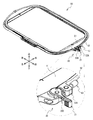
- 3 is a perspective view of an embroidery frame 50.
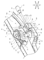
- FIG. 3 is an exploded perspective view of a tightening mechanism 30.
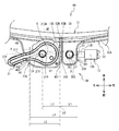
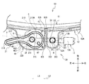
- FIG. It is a top view of the clamping mechanism 30 in case the lever 21 exists in a 1st position. It is a top view of the clamping mechanism 30 in case the lever 21 exists in a 2nd position. It is a top view of the clamping mechanism 30 in case the lever 21 exists in a specific position.
- 3 is an exploded perspective view of a tightening mechanism 300 of an embroidery frame 500.
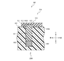
- FIG. It is sectional drawing of the fastening mechanism 300 of the II arrow direction in FIG.
- the sewing machine 1 includes a bed portion 11, a pillar portion 12, an arm portion 17, a head portion 14, and an embroidery frame transfer device 40.
- the bed portion 11 extends in the left-right direction.
- the pedestal 12 is erected upward from the right end of the bed 11.
- the arm portion 17 extends leftward from the upper end of the pedestal column portion 12 and faces the bed portion 11.
- the head 14 is connected to the tip of the arm 17.
- the embroidery frame transfer device 40 holds the embroidery frame 50 so as to be movable.
- the pedestal 12 has a sewing machine motor (not shown) inside.
- a main shaft is provided inside the arm portion 17.
- the main shaft is rotationally driven by a sewing machine motor.
- the head 14 is provided with a needle bar 6, a presser bar 8, and the like.
- a sewing needle 6A is detachably attached to the lower end of the needle bar 6.
- a presser foot 9 is detachably attached to the lower end portion of the presser bar 8.
- the needle bar 6 is driven in the vertical direction by the rotation of the main shaft.
- the embroidery frame transfer device 40 includes a holder (not shown), a main body 41, and a carriage 42.
- the holder is provided on the right side surface of the carriage 42.
- An embroidery frame 50 is detachably attached to the holder.
- the embroidery frame transfer device 40 can move the embroidery frame 50 in the front-rear direction and the left-right direction. As a result, the embroidery frame transfer device 40 can move the sewing object S held by the embroidery frame 50.
- the main body 41 includes an X-axis moving mechanism (not shown) and an X-axis motor (not shown) inside.
- the X-axis moving mechanism moves the carriage 42 in the left-right direction (X-axis direction) with the driving force of the X-axis motor.
- the carriage 42 includes a Y-axis moving mechanism (not shown) and a Y-axis motor (not shown).
- the Y-axis moving mechanism moves the holder in the front-rear direction (Y-axis direction) with the driving force of the Y-axis motor.
- the embroidery frame 50 holds the sewing object S in the horizontal direction.
- the embroidery frame 50 includes an outer frame 52, an inner frame 51, and a tightening mechanism 30.
- the outer frame 52 includes a frame-shaped portion 52A and a dividing portion 52B.
- the frame-like portion 52A is formed in a frame shape having a substantially rectangular shape in plan view.
- the dividing part 52B divides the substantially central part of the front part of the frame-like part 52A across the left-right direction and the front-rear direction.
- the inner frame 51 is formed in a substantially rectangular frame shape in plan view, and is fitted inside the outer frame 52.
- the inner frame 51 is opened in the vertical direction and faces the outer frame 52 in the horizontal direction.
- the tightening mechanism 30 is provided in the dividing part 52B.
- the tightening mechanism 30 is a mechanism for tightening the outer frame 52 against the inner frame 51.
- the tightening mechanism 30 includes a pair of screw mounting portions 22A and 22B, a lever 21, nuts 23 and 24, and an adjusting screw 13.
- the pair of screw mounting portions 22A and 22B are provided on both sides in the left-right direction of the dividing portion 52B and face each other.
- the screw mounting portion 22A is provided on the right side of the dividing portion 52B, and has a box shape extending in the front-rear direction of a substantially rectangular shape in plan view.
- the screw mounting portion 22A includes a first surface 301, a second surface 302, and a third surface 303.
- the first surface 301 faces right, the second surface 302 faces left, and the third surface 303 faces upward.
- the third surface 303 connects the upper ends of the first surface 301 and the second surface 302.
- the screw mounting portion 22A includes a through-hole portion 38 that opens in the left-right direction.
- the through-hole portion 38 is circular when viewed from the side.
- the through-hole portion 38 is provided with insertion hole portions 35 and 36.
- the insertion hole portion 35 is the right end portion of the through hole portion 38
- the insertion hole portion 36 is the left end portion of the through hole portion 38. That is, the insertion hole 35 is formed on the first surface 301, and the insertion hole 36 is formed on the second surface 302.
- the inner diameter of the insertion hole 36 is slightly larger than the inner diameter of the insertion hole 35.
- an insertion hole portion 37 is formed in the screw mounting portion 22A.
- the insertion hole 37 is formed in the third surface 303.
- the insertion hole portion 37 is a hole having a circular shape in plan view that opens upward.
- the insertion hole 37 extends in the vertical direction.
- the through-hole portion 38 and the insertion hole portion 37 intersect with each other inside the screw mounting portion 22A.
- an axis extending through the center of the insertion hole portion 37 in the vertical direction is referred to as a rotation axis A.
- the screw mounting portion 22B is provided on the left side of the dividing portion 52B and has a box shape extending in the left-right direction in a substantially rectangular shape in plan view.
- the screw mounting portion 22B includes a first surface 401, a second surface 402, and a third surface 403.
- the first surface 401 faces right, the second surface 402 faces left, and the third surface 403 faces upward.
- the third surface 403 connects the upper ends of the first surface 401 and the second surface 402.
- the screw mounting portion 22B includes a through-hole portion 48 that opens in the left-right direction.
- the through-hole portion 48 is circular when viewed from the side.
- the through hole 48 includes an insertion hole 45 and a hole 46.
- the insertion hole 45 is the right end of the through hole 48, and the hole 46 is the left end of the through hole 48. That is, the insertion hole 45 is formed in the first surface 401 and the hole 46 is formed in the second surface 402.
- the insertion hole 45 has a long hole shape in which the hole diameter extends in the front-rear direction when viewed from the right side, and has a long diameter that is approximately twice the outer diameter of the shaft part 13C of the adjusting screw 13 as an example.
- the hole 46 has a long hole shape having an inner diameter larger than the inner diameter of the insertion hole 45. The user can visually recognize the insertion hole 45 through the hole 46 from the left side.
- an insertion hole portion 47 is formed in the screw mounting portion 22B.
- the insertion hole 47 is formed in the third surface 403.
- the insertion hole portion 47 has a substantially circular shape in a plan view and is a circular hole in a plan view that opens upward.
- the insertion hole 47 extends in the vertical direction.
- the through-hole portion 48 and the insertion hole portion 47 intersect inside the screw mounting portion 22B.
- the axis extending through the center of the insertion hole 47 in the vertical direction is referred to as a rotation axis C.
- the lever 21 is rotatably held in the insertion hole portion 47 of the screw mounting portion 22B.
- the lever 21 includes a base portion 209, a disk body 216, an extending contact portion 217, and an operation portion 218.
- the base 209 is fitted into the insertion hole 47 so as to be rotatable.
- the rotation center of the base 209 is a rotation axis C.
- the base portion 209 includes a contact portion 213 and a pair of opposing wall portions 211.
- the contact portion 213 has a substantially rectangular parallelepiped shape extending in the vertical direction, and is disposed at a position shifted from the rotation axis C.
- the contact portion 213 includes a contact surface 213A.
- the contact surface 213A is a plane that faces the rotation axis C and faces clockwise in plan view.
- the contact surface 213A extends in the vertical direction.
- Each of the pair of opposing wall portions 211 protrudes from the upper end portion and the lower end portion of the contact portion 213 to one side.
- the pair of opposing wall portions 211 are arranged to face each other in the vertical direction with the contact portion 213 interposed therebetween. Therefore, the pair of opposing wall portions 211 have a C-shaped accommodation space 211A in a right side view.
- a later-described nut 24 is accommodated in the accommodating space 211A.
- the pair of opposing wall portions 211 has a substantially disk shape in plan view.
- the outer diameter of the pair of opposing wall portions 211 is substantially the same as the inner diameter of the insertion hole portion 47 of the screw mounting portion 22B.
- the pair of opposing wall portions 211 is slidably held in the insertion hole portion 47 in a state where the lever 21 is inserted into the screw mounting portion 22B.
- Each of the pair of opposed wall portions 211 has a pair of insertion hole portions 215.
- the pair of insertion holes 215 have a circular shape in plan view and open in the up-down direction.
- the pair of insertion holes 215 are arranged side by side in the vertical direction at a position eccentric from the rotation axis C.
- the center line of the pair of insertion holes 215 is referred to as a rotation axis B.
- the rotation axis B extends in the up-down direction at a position eccentric from the rotation axis C.
- the disk body 216 is a disk centered on the rotation axis C.
- the disc body 216 is fixed to the upper portion of the upper facing wall portion 211.
- the disc body 216 includes an insertion hole 214 that opens in the vertical direction.
- the insertion hole 214 extends in the vertical direction and is formed integrally with the upper insertion hole 215.
- the inner diameter of the insertion hole 214 is the same as the inner diameter of the pair of insertion holes 215.
- the extended contact portion 217 extends from the end of the disc body 216 to one side.
- One end of the extended contact portion 217 is connected to the operation portion 218.
- the operation part 218 extends downward from the extending contact part 217 (see FIG. 3). The user can pick up the operation unit 218 and operate (that is, rotate) the lever 21.
- the nut 23 has a cylindrical shape extending in the vertical direction.
- the axis of the nut 23 is the rotation axis A.
- the nut 23 is inserted through the insertion hole 37 of the screw mounting portion 22A.
- the nut 23 is slidably held in the insertion hole 37 around the rotation axis A.
- the nut 23 has a through hole 23A penetrating in the left-right direction through a substantially central portion in the vertical direction of the nut 23 (see FIG. 3).
- the through hole 23 ⁇ / b> A is disposed at a vertical position that is inside the through hole portion 38.
- the outer diameter of the nut 23 is substantially the same as the inner diameter of the insertion hole 37.
- the nut 24 has a cylindrical shape extending in the vertical direction.
- the axis of the nut 24 coincides with the rotation axis B.
- the nut 24 is provided on the lever 21. Specifically, the nut 24 is inserted through the insertion hole 214 of the lever 21 and the pair of insertion holes 215 of the lever 21.
- the insertion hole 214 and the pair of insertion holes 215 hold the nut 24 slidably. In other words, the nut 24 is held by the lever 21.
- the nut 24 can be rotated inside the lever 21 with the rotation axis B that is eccentric from the rotation axis C as the rotation center.
- the nut 24 has a screw hole 24A at a substantially central portion in the vertical direction.
- the screw hole 24 ⁇ / b> A opens in the left-right direction, and is disposed at a vertical position that is inside the through-hole portion 48.
- the adjusting screw 13 includes an operation portion 13A, a contact portion 13B, and a shaft portion 13C.
- 13 A of operation parts are the column shape extended in the left-right direction (refer FIG. 3), and are arrange
- the contact portion 13B has a cylindrical shape extending in the left-right direction.
- the contact portion 13B extends to the left from the left end of the operation portion 13A and contacts the first surface 301.
- the outer diameter of the contact portion 13B is smaller than the outer diameter of the operation portion 13A. Further, the outer diameter of the contact portion 13B is larger than the inner diameter of the insertion hole portion 35 of the first surface 301.
- the adjustment screw 13 is restricted from moving leftward by the contact between the first surface 301 and the contact portion 13B.
- the shaft portion 13C is a shaft extending leftward from the left end portion of the contact portion 13B.
- the outer diameter of the shaft portion 13C is smaller than the outer diameter of the contact portion 13B.
- the outer diameter of the shaft portion 13 ⁇ / b> C is smaller than the inner diameter of the through-hole portion 38 and smaller than the inner diameter of the through-hole portion 48.
- the shaft portion 13C is inserted through the through hole portion 38 of the screw mounting portion 22A, the through hole 23A of the nut 23, and the through hole portion 48 of the screw mounting portion 22B.
- the shaft portion 13 ⁇ / b> C is screwed into the screw hole 24 ⁇ / b> A of the nut 24.
- the outer diameter of the shaft portion 13 ⁇ / b> C of the adjusting screw 13 is smaller than the inner diameter of the through hole 23 ⁇ / b> A of the nut 23.
- the fitting between the shaft portion 13C and the through hole 23A is a clearance fit.
- the rotation position of the lever 21 will be described with reference to FIGS.
- the lever 21 rotates between the first position (see FIG. 4) and the second position (see FIG. 6) about the rotation axis C via a specific position (see FIG. 5).
- the first position and the second position are both end positions of the rotation range of the lever 21.
- the lever 21 rotates from the first position to the second position by rotating clockwise around the rotation axis C in plan view.
- the specific position is a rotation position of the lever 21 between the first position and the second position. In the process in which the lever 21 is rotated from the first position to the second position, the gap formed between the outer frame 52 and the inner frame 51 is reduced, and the outer frame 52 extends in the extending direction.
- the frame 51 is in close contact with the sewing object S. Regardless of the rotation position of the lever 21, the contact portion 13B of the adjusting screw 13 maintains a state of contacting the first surface 301 of the screw mounting portion 22A.
- the rotation shaft B When the lever 21 is in the first position (see FIG. 4), the rotation shaft B is disposed on the left front side with respect to the rotation shaft C, and the shaft portion 13C of the adjusting screw 13 extends from the right rear to the left front. .
- the abutting surface 213A faces the right front side behind the shaft portion 13C.
- the axis of the nut 24 (that is, the rotation axis B) is disposed on the front side of the rotation axis C that is the rotation center of the lever 21.
- a virtual straight line (hereinafter referred to as a virtual straight line V) that intersects with the rotation axis C and the rotation axis B orthogonally extends from the right rear to the left front, and is not parallel to the direction in which the shaft portion 13C extends. become.
- the rotation shaft B When the lever 21 is at a specific position (see FIG. 5), the rotation shaft B is disposed on the left side with respect to the rotation shaft C, and the shaft portion 13C extends in the left-right direction.
- the contact surface 213A is opposed to the shaft portion 13C from behind with a gap.
- the rotation axis B of the nut 24 is located on the left side of the rotation axis B when the lever 21 is in the first position.
- the shaft portion 13C of the adjusting screw 13 When the lever 21 is in a specific position, the shaft portion 13C of the adjusting screw 13 extends in the left-right direction.
- the virtual straight line V extends in the left-right direction and is parallel to the shaft portion 13C.
- the rotation shaft B is disposed on the left rear side with respect to the rotation shaft C, and the shaft portion 13C extends from the right front toward the left rear.
- the abutting surface 213A faces and abuts against the shaft portion 13C from the rear.
- the virtual straight line V extends from the left rear to the right front, and is not parallel to the direction in which the shaft portion 13C extends.
- the distances L1 and L2, the specific distance L3, and the distances L4 and L5 will be described with reference to FIGS.
- the distance L1 is the shortest distance in the left-right direction from the first surface 301 to the second surface 302 (see FIG. 5).
- the distance L1 is constant regardless of the rotation position of the lever 21.
- the distance L2 is the shortest distance in the left-right direction from the second surface 302 of the screw mounting portion 22A to the first surface 401 of the screw mounting portion 22B.
- the tightening force of the tightening mechanism 30 increases as the distance L2 is shorter in the frame tightening.
- the specific distance L3 is the shortest distance in the left-right direction from the first surface 401 of the screw mounting portion 22B to the rotation axis B of the nut 24.
- the distance L2 and the specific distance L3 change according to the rotation position of the lever 21.
- the distance L4 is the length of the shaft portion 13C of the adjusting screw 13 in the left-right direction.
- the distance L5 is the shortest distance between the first surface 401 and the hole 46 in the left-right direction.
- the distance L2 is shorter than when the lever 21 is at the first position and shorter than when the lever 21 is at the second position.
- the distance L2 is the shortest. That is, at the specific position of the lever 21, the pair of screw mounting portions 22A and 22B are closest to each other.
- the specific distance L3 is longer by the distance that the nut 24 (in other words, the rotation axis B) moves to the left in the left-right direction than when the lever 21 is in the first position.
- the nut 24 is located on the leftmost side.
- the left end of the shaft portion 13 ⁇ / b> C of the adjusting screw 13 is closest to the second surface 402.
- the sum (L1 + L2 + L5) of the distance L1, the distance L2, and the distance L5 is longer than the distance L4 (see FIG. 5).
- the left end portion of the shaft portion 13 ⁇ / b> C does not protrude leftward from the second surface 402 regardless of the rotation position of the lever 21. That is, regardless of the rotation position of the lever 21, the left end portion of the shaft portion 13C is difficult for the user to visually recognize, so that the appearance of the embroidery frame 50 is improved.
- the distance L2 is shorter than when the lever 21 is in the first position. In the second position, the distance L2 is slightly longer than when the lever 21 is in the specific position.
- the specific distance L3 is longer by the moving distance of the nut 24 in the left-right direction than when the lever 21 is at the first position. Further, when the lever 21 is in the second position, the specific distance L3 is slightly shorter by the moving distance in the left-right direction than when the lever 21 is in the specific position.
- the frame tightening of the embroidery frame 50 will be described with reference to FIGS.
- the lever 21 Prior to the start of frame tightening, the lever 21 is disposed at the first position. After arranging the sewing object S between the outer frame 52 and the inner frame 51, the user picks the operation unit 218 and rotates the lever 21 toward the second position.
- the nut 24 rotates about the rotation axis C and moves to the left and rear.
- the nut 24 rotates about the rotation axis B in the clockwise direction in plan view.
- the adjusting screw 13 rotates clockwise in plan view around the contact position between the contact portion 13B and the first surface 301.
- the rotation of the shaft portion 13C is not restricted by the through hole 23A. Since the nut 24 moves to the left side, the adjusting screw 13 screwed with the nut 24 is urged to the left.
- the screw mounting portion 22A Since the contact portion 13B is in contact with the first surface 301 of the screw mounting portion 22A, the screw mounting portion 22A is biased to the left side. Accordingly, the screw mounting portion 22A moves to the left side. Thereby, the distance L2 between the pair of screw mounting portions 22A and 22B gradually decreases as the lever 21 rotates toward the specific position. Therefore, the outer frame 52 is gradually tightened with respect to the inner frame 51. As the lever 21 rotates toward the specific position, the force required to rotate the lever 21 increases. Until the lever 21 reaches the specific position, the outer frame 52 is in close contact with the inner frame 51 in the extending direction, and the sewing object S is sandwiched between the outer frame 52 and the inner frame 51. That is, the outer frame 52 and the inner frame 51 sandwich the sewing object S in the horizontal direction.
- the nut 24 further rotates around the rotation axis C and moves to the right side and the rear side. .
- the nut 24 further rotates about the rotation axis B in the clockwise direction in plan view.
- the adjusting screw 13 further rotates clockwise in plan view around the contact position between the contact portion 13B and the first surface 301. Also at this time, the rotation of the shaft portion 13C is not restricted by the through hole 23A. Since the nut 24 moves to the right side, the biasing force toward the left side of the adjusting screw 13 is weakened, and the screw mounting portion 22A slightly returns to the right side.
- the distance L2 between the pair of screw mounting portions 22A and 22B gradually increases as the lever 21 rotates toward the second position. Therefore, the outer frame 52 is slightly loosened with respect to the inner frame 51. Therefore, as the lever 21 rotates from the specific position toward the second position, the force required to rotate the lever 21 decreases.
- the contact surface 213A contacts the shaft portion 13C, and the lever 21 reaches the second position.
- the contact between the contact surface 213A and the shaft portion 13C restricts the rotation of the lever 21 about the rotation axis C in the clockwise direction in plan view, so that the lever 21 is positioned at the second position.
- the tightening force loosened with the rotation of the lever 21 from the specific position to the second position is extremely smaller than the tightening force that increases with the rotation of the lever 21 from the first position to the specific position. Therefore, there is no problem with the tightening force of the tightening mechanism 30 at the second position of the lever 21. Even when the lever 21 is in the second position, the outer frame 52 sandwiches the sewing object S between the outer frame 52 and the inner frame 51. Therefore, the user can attach the sewing object S to the embroidery frame 50 by tightening the outer frame 52 with respect to the inner frame 51 simply by rotating the lever 21 from the first position to the second position.
- the adjustment of the distance L2 will be described with reference to FIG.
- the user can adjust the distance L2 between the pair of screw mounting portions 22A and 22B by rotating the operation portion 13A in the right side view, clockwise direction, or counterclockwise direction.
- the user turns the operation unit 13A clockwise when viewed from the right side. Since the left end of the contact portion 13B is in contact with the first surface 301 of the screw mounting portion 22A, a force directed to the right is applied to the nut 24. Since the position of the nut 24 is fixed in the lever 21, a force directed to the right is applied to the screw mounting portion 22B.
- the screw mounting portion 22B moves to the right and approaches the screw mounting portion 22A. Therefore, the distance L2 becomes small.
- the left end of the contact portion 13B is in contact with the first surface 301 of the screw mounting portion 22A, so that the nut 24 faces leftward. Power is added. Since the position of the nut 24 is fixed in the lever 21, a force directed to the left is applied to the screw mounting portion 22B. The screw mounting portion 22B moves to the left and moves away from the screw mounting portion 22A. Accordingly, the distance L2 is increased.
- the user can adjust the tightening force (in other words, the clamping force) of the sewing object S by the tightening mechanism 30 when the lever 21 rotates from the first position to the second position.
- the user may adjust the distance L2 as appropriate according to the thickness of the sewing object S.
- the embroidery frame 50 includes the outer frame 52, the inner frame 51, the pair of screw mounting portions 22 ⁇ / b> A and 22 ⁇ / b> B, and the lever 21.
- the outer frame 52 includes a frame-shaped portion 52A formed in a frame shape and a dividing portion 52B obtained by dividing a part of the frame-shaped portion 52A.
- the inner frame 51 is fitted inside the outer frame 52, and the sewing object S can be held between the inner frame 51 and the outer frame 52.
- the pair of screw mounting portions 22A and 22B are provided in the dividing portion 52B and are disposed to face each other.
- the lever 21 is provided in the screw mounting portion 22B and is rotatable about a rotation axis C to a first position and a second position.
- the nut 24 is slidably held at a position eccentric from the rotation center of the lever 21.
- the adjusting screw 13 is mounted across the pair of screw mounting portions 22A and 22B and is screwed into the nut 24.
- the second position of the lever 21 is such that the specific distance L3, which is the shortest distance between the first surface 401 of the screw mounting portion 22B facing the other screw mounting portion 22A and the nut 24, is the first position of the lever 21. Longer than the specific distance L3.
- the nut 24 rotates together with the lever 21 while maintaining the state of being engaged with the adjusting screw 13.
- the outer frame 52 is fastened to the inner frame 51 by the pair of screw mounting portions 22A and 22B approaching each other. Therefore, the user can easily tighten the outer frame 52 to the inner frame 51 simply by rotating the lever 21 from the first position to the second position. Therefore, the embroidery frame 50 can be easily tightened.
- the lever 21 is rotatable through a specific position between the first position and the second position.
- the specific position is a rotation position of the lever 21 having the longest specific distance L3.
- the lever 21 rotates to the second position via a specific position where the most force is required to rotate the lever 21.
- the outer frame 52 is tightened with respect to the inner frame 51. Therefore, the force required for the user to rotate the lever 21 from the second position toward the specific position increases as the lever 21 approaches the specific position. Thereby, the lever 21 in the second position is difficult to turn toward the specific position. Therefore, since the embroidery frame 50 can stabilize the second position of the lever 21, the embroidery frame 50 can maintain an appropriate tightening force.
- the insertion hole 45 has a long hole shape extending in the front-rear direction, and has a long diameter that is approximately twice the outer diameter of the shaft part 13C of the adjusting screw 13 as an example.
- the nut 24 that is eccentric from the rotation axis C that is the rotation center of the lever 21 rotates in the front-rear direction, which is the major axis direction of the insertion hole 45. Since the long diameter of the insertion hole 45 is about twice the outer diameter of the shaft 13C of the adjusting screw 13, the embroidery frame 50 is in contact with the inner peripheral surface of the insertion hole 45 and the shaft 13C of the adjusting screw 13. Can be suppressed. Therefore, since the lever 21 is easy to rotate, the user can easily tighten the frame.
- the contact surface 213A is provided on the lever 21 and contacts the shaft portion 13C of the adjusting screw 13 in the process of turning the lever 21 toward the second position. Due to the contact between the contact surface 213A of the contact portion 213 and the shaft portion 13C, the lever 21 at the second position is restricted from turning clockwise around the rotation axis C in plan view. Further, the lever 21 is difficult to rotate from the second position toward the specific position. Since the lever 21 is stably positioned at the second position, the tightening mechanism 30 of the embroidery frame 50 can stabilize the tightening force with respect to the sewing object S.
- the embroidery frame 50 can be reduced in size.
- the screw mounting portion 22B includes a through-hole portion 48 that opens in the left-right direction.
- the adjusting screw 13 is inserted into the through hole 48.
- the user can easily visually recognize the adjusting screw 13 through the hole 46. Therefore, the user can easily tighten the frame.
- the rotation axis C of the lever 21 extends parallel to the vertical direction in which the inner frame 51 opens. Even if the lever 21 rotates, the position of the lever 21 in the vertical direction in which the inner frame 51 opens does not change. Therefore, the user can easily turn the lever 21.
- the sum of the distance L1, the distance L2, and the distance L5 is longer than the distance L4 (see FIG. 5).
- the distance L1 and the distance L5 are constant regardless of the rotation position of the lever 21, and the distance L2 is the shortest when the lever 21 is at a specific position. Therefore, regardless of the position of the lever 21, the sum of the distance L1, the distance L2, and the distance L5 is longer than the distance L4. That is, the shaft portion 13 ⁇ / b> C of the adjusting screw 13 does not protrude leftward from the hole portion 46. It is difficult for the user to visually recognize the left end portion of the shaft portion 13C. Therefore, the appearance of the embroidery frame 50 can be improved.
- the nut 24 is an example of the “nut” in the present invention.
- the through hole 48 is an example of the “first insertion hole” in the present invention.
- the abutting surface 213A is an example of the “regulating means” in the present invention.
- the through hole 38 is an example of the “second insertion hole” in the present invention.
- the present invention is not limited to the above embodiment, and various modifications are possible.
- the configuration of the sewing machine 1 may be changed as appropriate.
- the sewing machine 1 may be a sewing machine for other uses such as a multi-needle sewing machine.
- the embroidery frame transfer device 40 may be formed integrally with the sewing machine 1.
- the embroidery frame 50 that can be mounted on the embroidery frame transfer device 40 only needs to have an inner frame 51, an outer frame 52, and a tightening mechanism 30.
- the sewing object S is clamped in the vertical direction instead of the horizontal direction.
- the embroidery frame 50 may be used.
- the shape of the embroidery frame 50 may be changed as appropriate.
- the embroidery frame 50 may be circular.
- the configuration of the tightening mechanism 30 may be changed as appropriate. You may use the structure of the clamping mechanism 30 for apparatuses other than a sewing machine.
- the lever 21 is mounted on the screw mounting portion 22B, but may be mounted on the screw mounting portion 22A.
- the nut 24 and the like are also mounted on the screw mounting portion 22A, and the adjusting screw 13 is inserted from the screw mounting portion 22B.
- the nut 23 may not be provided. In this case, any mechanism may be used as long as the distance L2 between the pair of screw mounting portions 22A and 22B can be adjusted.
- the nut 23 may be screwed with the adjusting screw 13.
- the adjusting screw 13 is inserted from the screw mounting portion 22A toward the screw mounting portion 22B, but may be inserted from the reverse side.
- the lever 21 has been tightened at the second position, but may be tightened at other positions. For example, tightening may be completed at a specific position.
- the insertion hole 45 has a major axis that is approximately twice the outer diameter of the shaft part 13C of the adjusting screw 13. However, the major axis of the insertion hole 45 may be twice or more the outer diameter of the shaft part 13C. Thereby, possibility that the insertion hole part 45 and the axial part 13C will contact can be reduced more.
- the screw mounting portion 22B may be provided with, for example, an opening portion whose left portion is closed instead of including the through hole portion 48 that opens in the left-right direction.
- the hole 46 may not be formed on the second surface 402.
- the left end portion of the shaft portion 13 ⁇ / b> C may protrude leftward from the second surface 402 at a specific position of the lever 21. Even in this case, at the first position and the second position of the lever 21, if the left end portion of the shaft portion 13C does not protrude from the second surface 402, the lever 21 is located between the first position and the second position. When rotating between, the user hardly sees the left end portion of the shaft portion 13C. Therefore, the appearance of the embroidery frame 50 can be improved.
- the embroidery frame 500 includes a tightening mechanism 300 instead of the tightening mechanism 30.
- the tightening mechanism 300 of the embroidery frame 500 includes a screw mounting portion 220B instead of the screw mounting portion 22B.
- the screw mounting portion 220B is different from the screw mounting portion 22B in that it includes a hole 603, a coil spring 602, and a pin 601.
- the hole portion 603 is formed in the third surface 403 and is disposed at the left rear position of the insertion hole portion 47 (see FIG. 7).
- the hole 603 is a hole extending in the vertical direction (see FIG. 8).
- the coil spring 602 is disposed inside the hole 603 in a posture along the vertical direction.
- the coil spring 602 has an outer diameter that is substantially the same as the inner diameter of the hole 603.
- the lower end of the coil spring 602 contacts the bottom surface of the hole 603.
- the pin 601 extends in the vertical direction, which is the axial direction thereof, and is disposed above the coil spring 602.
- the pin 601 has substantially the same outer diameter as the inner diameter of the hole 603.
- the pin 601 compresses the coil spring 602 downward (see FIGS. 7 and 8). That is, the coil spring 602 biases the pin 601 upward.
- the tightening mechanism 300 includes a lever 210 instead of the lever 21.
- the lever 210 is different from the lever 21 in that it includes a wall portion 610.
- the wall portion 610 is provided at the rear portion of the base portion 209 of the lever 210 and extends in an arc shape around the rotation axis C (see FIG. 7).
- the wall portion 610 includes a sliding surface 610A and a hole portion 610B.
- the sliding surface 610 ⁇ / b> A is disposed at a position protruding outward in the radial direction around the rotation axis C from the base 209.
- the sliding surface 610A is formed at a position where the shortest distance from the rotation axis C is the distance L6 in the lower surface of the wall portion 610, and extends in an arc shape around the rotation axis C.
- the hole 610B is formed at a position where the shortest distance from the rotation axis C is the distance L6 in the lower surface of the wall 610, and opens downward (see FIGS. 7 and 8).
- the hole 610B is formed at the left end of the sliding surface 610A (see FIG. 7).
- the hole 610 ⁇ / b> B has an inner peripheral surface 613 and a tapered surface 611.
- the inner peripheral surface 613 extends in the axial direction of the pin 601.
- One end of the tapered surface 611 is connected to the lower end of the inner peripheral surface 613 of the hole 610B.
- the other end of the tapered surface 611 is connected to the sliding surface 610A.
- the shortest distance between the pin 601 and the rotation axis C and the shortest distance between the sliding surface 610A and the rotation axis C are the distance L6. Therefore, when the lever 210 rotates, the upper end of the pin 601 slides with the sliding surface 610A.
- the frame tightening of the embroidery frame 500 will be described.
- the lever 210 Prior to the start of frame tightening, the lever 210 is disposed at the first position.
- the sliding surface 610A contacts the upper end of the pin 601 biased upward.
- the user picks the operation unit 218 and rotates the lever 210 toward the second position.
- the sliding surface 610A rotates clockwise around the rotation axis C while sliding on the upper end of the pin 601. That is, when the lever 210 is rotated to the second position, the sliding surface 610A rotates clockwise about the rotation axis C while sliding on the upper end of the pin 601.
- the pin 601 slides with the tapered surface 611. Since the pin 601 is biased upward by the coil spring 602, the upper end of the pin 601 moves upward while sliding on the tapered surface 611. When the lever 210 further reaches the second position, the pin 601 is further biased upward by the upward biasing force of the coil spring 602. As a result, the pin 601 is inserted into the hole 610B. In the embroidery frame 500, when the lever 210 is in the second position, the pin 601 is inserted into the hole 610B, so that the rotation of the lever 210 in the clockwise direction and the counterclockwise direction is restricted. The lever 210 is difficult to rotate from the second position. Therefore, the embroidery frame 500 can maintain an appropriate tightening force.
- the embroidery frame 500 can maintain an appropriate tightening force.
- the tapered surface 611 guides the pin 601 toward the inside of the hole 610B, so that the pin 601 is easily inserted into the hole 610B. Therefore, the lever 210 is easy to rotate to the second position.
- the present invention is not limited to the above embodiment, and various modifications are possible.
- the pin 601 is inserted into the hole 610B at the second position of the lever 210, but may be arranged to be inserted into the hole 610B at a specific position, for example.
- the lever 210 can be positioned at a position where the outer frame 52 is most strongly tightened with respect to the inner frame 51.
- it is further preferable that the position of the contact surface 213 ⁇ / b> A is in contact with the shaft portion 13 ⁇ / b> C at the specific position of the lever 210.
- the hole portion 603 is provided in the screw mounting portion 220B, but may be provided in the wall portion 610 of the lever 210.
- the hole 610B is provided in the screw mounting portion 220B, and the coil spring 602 and the pin 601 are inserted through the hole 610B provided in the screw mounting portion 220B, and the lever 210 is in the second position.
- the pin 601 is inserted into the part 610B.
- the pin 601 is inserted into the hole 610B by the biasing force of the coil spring 602 when the lever 210 is in the second position, but the pin 601 may always protrude from the third surface 403.
- a groove may be provided on the sliding surface 610A, the pin 601 may be disposed inside the groove, and the pin 601 may move.
- the tapered surface 611 may not be provided.
- the rotation axis C of the lever 210 extends in the vertical direction, but may extend in the front-rear direction, for example. In this case, the lever 210 rotates in the vertical direction.
- the pin 601, the sliding surface 610 ⁇ / b> A, and the hole 610 ⁇ / b> B are examples of the “regulating means” of the present invention.
- the coil spring 602 is an example of the “biasing member” in the present invention.
Landscapes
- Engineering & Computer Science (AREA)
- General Engineering & Computer Science (AREA)
- Textile Engineering (AREA)
- Mechanical Engineering (AREA)
- Sewing Machines And Sewing (AREA)
Abstract
容易に枠締めできる刺繍枠を提供する。 刺繍枠50は、外枠52、内枠51、一対の螺子装着部22A、22B、レバー21、ナット24、及び調節螺子13を備える。外枠52は、分断部52Bを備える。内枠51は、外枠52との間に縫製対象物を挟持可能である。一対の螺子装着部22A、22Bは、分断部52Bに互いに対向して配置される。螺子装着部22Bには、第一面401が設けられる。レバー21は、螺子装着部22Bに設けられる。ナット24は、レバー21の回動中心から偏心した位置に摺動可能に保持される。調節螺子13は、一対の螺子装着部22A、22Bに亘って装着され、ナット24と螺合する。レバー21が回動範囲の一端から他端に向けて回動する場合、第一面401とナット24との最短の距離である特定距離L3は、小さくなる。
Description
本発明は、刺繍枠に関する。
外枠を内枠に対して締め付ける刺繍枠が公知である。例えば、特許文献1の刺繍枠は、外枠、内枠、一対の螺子装着部、調節螺子、操作軸、及び連結機構等を備える。一対の螺子装着部は、外枠の枠部分を分断した分断部に設けられる。調節螺子は、一対の螺子装着部に亘って装着され、一対の螺子装着部間の間隔を調節できる。ユーザは、操作軸を操作することで、調節螺子を回動する。連結機構は、操作軸の回動トルクを調節螺子に伝達する。ユーザが操作軸を使用して調節螺子を回動することで、一対の螺子装着部間の間隔は狭まる。刺繍枠は、外枠と内枠の間に布を挟んだ状態で、外枠を内枠に対して締め付ける。
上記刺繍枠では、ユーザが外枠を内枠に対して締め付けるとき、内枠からの反力が外枠に対して作用する。従って、ユーザが、適切な枠締めがなされる回転位置まで調節螺子を回転しようとすると、過大な力が必要となる虞がある。よって、枠締めの作業がユーザにとって煩わしいという虞がある。
本発明の目的は、容易に枠締めできる刺繍枠を提供することである。
本発明の刺繍枠は、枠状に形成された枠状部と、前記枠状部の一部を分断した分断部とを備える外枠と、前記外枠の内側に嵌め込まれ、前記外枠との間に縫製対象物を挟持可能な内枠と、前記分断部に設けられ、互いに対向して配置される一対の螺子装着部と、一方の前記螺子装着部に設けられ、回動軸を中心として第一位置と第二位置とに回動可能なレバーと、前記レバーに設けられ、前記レバーの回動中心から偏心した位置に摺動可能に保持されるナットと、前記一対の螺子装着部に亘って装着され、前記ナットと螺合する調節螺子とを備え、前記第二位置は、前記一方の螺子装着部のうちで他方の前記螺子装着部に対向する第一面と、前記ナットとの最短の距離である特定距離が、前記第一位置における前記特定距離よりも長い位置であることを特徴とする。
本発明の刺繍枠では、ユーザがレバーを第一位置から第二位置に回動すると、ナットは、調節螺子と螺合した状態を維持してレバーと共に回動する。一対の螺子装着部が互いに近づくことで、外枠は内枠に対して締め付けられる。従って、ユーザは、レバーを第一位置から第二位置に回動するだけで外枠を内枠に容易に締め付けることができる。よって、刺繍枠は、容易に枠締めできる。
図1に示すように、ミシン1は、ベッド部11、脚柱部12、アーム部17、頭部14、及び刺繍枠移送装置40を備える。以下の説明では、図中の矢印によって示す前後方向、左右方向、上下方向を使用する。ベッド部11は、左右方向に延びる。脚柱部12は、ベッド部11の右端部から上方へ立設される。アーム部17は、脚柱部12の上端から左方へ延び、ベッド部11に対向する。頭部14は、アーム部17の先端部に連結する。刺繍枠移送装置40は、刺繍枠50を移動可能に保持する。
脚柱部12は、内部にミシンモータ(図示略)を備える。アーム部17の内部には、主軸が設けられる。主軸は、ミシンモータにより回転駆動される。頭部14には、針棒6、及び押え棒8等が設けられる。針棒6の下端には、縫針6Aが着脱可能に装着される。押え棒8の下端部には、押え足9が着脱可能に取り付けられる。針棒6は、主軸の回転により上下方向に駆動する。
図1に示すように、刺繍枠移送装置40はホルダ(図示略)、本体部41、及びキャリッジ42を備える。ホルダは、キャリッジ42の右側面に設けられる。ホルダには、刺繍枠50が着脱可能に装着される。刺繍枠移送装置40は、刺繍枠50を前後方向と左右方向とに移動可能である。これにより、刺繍枠移送装置40は、刺繍枠50に保持された縫製対象物Sを移動可能である。
本体部41は、X軸移動機構(図示略)及びX軸モータ(図示略)を内部に備える。X軸移動機構は、X軸モータの駆動力で、キャリッジ42を左右方向(X軸方向)に移動させる。
キャリッジ42は、Y軸移動機構(図示略)、及びY軸モータ(図示略)を備える。Y軸移動機構は、Y軸モータの駆動力で、ホルダを前後方向(Y軸方向)に移動させる。
図1~図3を参照して、刺繍枠50について説明する。刺繍枠50は、水平方向に縫製対象物Sを挟持する。図2に示すように、刺繍枠50は、外枠52、内枠51、及び締付機構30を有する。外枠52は、枠状部52A、及び分断部52Bを備える。枠状部52Aは、平面視略長方形の枠状に形成される。分断部52Bは、枠状部52Aの前部の略中央部を左右方向と前後方向とに亘って分断する。内枠51は、平面視略長方形の枠状に形成され、外枠52の内側に嵌め込まれる。内枠51は、上下方向に開口しており、水平方向に外枠52に対向する。締付機構30は、分断部52Bに設けられる。締付機構30は、外枠52を内枠51に対して締め付ける機構である。
図3を参照して、締付機構30の構成を説明する。締付機構30は、一対の螺子装着部22A、22B、レバー21、ナット23、24、及び調節螺子13を備える。一対の螺子装着部22A、22Bは、分断部52Bの左右方向における両側に設けられ、互いに対向する。螺子装着部22Aは、分断部52Bの右側に設けられ、平面視略長方形の前後方向に延びる箱状である。螺子装着部22Aは、第一面301、第二面302、及び第三面303を備える。第一面301は右方を向き、第二面302は左方を向き、第三面303は上方を向く。第三面303は、第一面301と第二面302の夫々の上端を接続する。
螺子装着部22Aは、左右方向に開口する貫通孔部38を備える。貫通孔部38は側面視円形である。貫通孔部38には、挿入穴部35、36が設けられる。挿入穴部35は、貫通孔部38の右端部であり、挿入穴部36は、貫通孔部38の左端部である。即ち、挿入穴部35は、第一面301に形成され、挿入穴部36は、第二面302に形成される。挿入穴部36の内径は、挿入穴部35の内径よりも若干大きい。また、螺子装着部22Aには、挿通穴部37が形成される。挿通穴部37は、第三面303に形成される。挿通穴部37は、上方に向けて開口する平面視円形の穴である。挿通穴部37は、上下方向に延びる。貫通孔部38と挿通穴部37は、螺子装着部22Aの内部で交わる。以下、挿通穴部37の中心を通り上下方向に延びる軸線を回動軸Aという。
螺子装着部22Bは、分断部52Bの左側に設けられ、平面視略長方形の左右方向に延びる箱状である。螺子装着部22Bは、第一面401、第二面402、及び第三面403を備える。第一面401は右方を向き、第二面402は左方を向き、第三面403は上方を向く。第三面403は、第一面401と第二面402の夫々の上端を接続する。
螺子装着部22Bは、左右方向に開口する貫通孔部48を備える。貫通孔部48は側面視円形である。貫通孔部48は、挿入穴部45、及び穴部46を含む。挿入穴部45は、貫通孔部48の右端部であり、穴部46は、貫通孔部48の左端部である。即ち、挿入穴部45は、第一面401に形成され、穴部46は、第二面402に形成される。挿入穴部45は、右側面視で穴径が前後方向に延びる長穴状であり、一例として調節螺子13の軸部13Cの外径の約二倍の長径を有する。穴部46は、挿入穴部45の内径よりも大きい内径を有する長穴状である。尚、ユーザは、左側から穴部46を介して挿入穴部45を視認できる。
また、螺子装着部22Bには、挿通穴部47が形成される。挿通穴部47は、第三面403に形成される。挿通穴部47は、平面視略円形状であり、上方に向けて開口する平面視円形の穴である。挿通穴部47は上下方向に延びる。貫通孔部48と挿通穴部47は、螺子装着部22Bの内部で交わる。以下、挿通穴部47の中心を通り上下方向に延びる軸線を回動軸Cという。
レバー21は、螺子装着部22Bの挿通穴部47に回動可能に保持される。レバー21は、基部209、円板体216、延接部217、及び操作部218を備える。基部209は挿通穴部47に回動可能に嵌め込まれる。基部209の回動中心は回動軸Cである。基部209は、当接部213、及び一対の対向壁部211を備える。当接部213は、上下方向に延びる略直方体状であり、回動軸Cからずれた位置に配置される。当接部213は当接面213Aを備える。当接面213Aは、回動軸Cを中心として平面視時計回り側を向く平面である。当接面213Aは上下方向に延びる。
一対の対向壁部211は夫々、当接部213の上端部と下端部から一方へ突出する。即ち、一対の対向壁部211は、当接部213を挟んで上下方向に対向して配置される。故に、一対の対向壁部211は、右側面視でC字の収容空間211Aを有する。収容空間211Aには後述のナット24が収容される。
一対の対向壁部211は、平面視略円板状である。一対の対向壁部211の外径は、螺子装着部22Bの挿通穴部47の内径と略同じである。一対の対向壁部211は、レバー21が螺子装着部22Bに挿通された状態で、挿通穴部47内で摺動可能に保持される。一対の対向壁部211は夫々、一対の挿通穴部215を有する。一対の挿通穴部215は、平面視円形状であり、上下方向に開口する。一対の挿通穴部215は、回動軸Cから偏心した位置にて、上下方向に並んで配置される。以下、一対の挿通穴部215の中心線を回動軸Bという。回動軸Bは、回動軸Cから偏心した位置にて上下方向に延びる。
円板体216は、回動軸Cを中心とした円板である。円板体216は、上側の対向壁部211の上部に固定される。円板体216は、上下方向に開口する挿通穴部214を備える。挿通穴部214は、上下方向に延び、上側の挿通穴部215と一体的に形成される。挿通穴部214の内径は、一対の挿通穴部215の内径と同じである。延接部217は、円板体216の端部から一方側に延びる。延接部217の一方側の端部は、操作部218と接続する。操作部218は、延接部217から下方へ延びる(図3参照)。ユーザは、操作部218を摘み、レバー21を操作(即ち回動)できる。
ナット23は、上下方向に延びる円柱状である。ナット23の軸線は、回動軸Aである。ナット23は、螺子装着部22Aの挿通穴部37に挿通されている。ナット23は、回動軸Aを中心として、挿通穴部37で摺動可能に保持されている。ナット23は、ナット23の上下方向略中央部を左右方向に貫通する貫通穴23Aを有する(図3参照)。貫通穴23Aは、貫通孔部38の内側となる上下方向位置に配置される。ナット23の外径は挿通穴部37の内径と略同じである。
ナット24は、上下方向に延びる円柱状である。ナット24の軸線は、回動軸Bと一致する。ナット24は、レバー21に設けられる。具体的には、ナット24は、レバー21の挿通穴部214とレバー21の一対の挿通穴部215とに挿通されている。挿通穴部214と一対の挿通穴部215とは、ナット24を摺動可能に保持する。換言すれば、ナット24はレバー21に保持される。これにより、ナット24は、回動軸Cから偏心した位置である回動軸Bを回動中心として、レバー21の内部で回動可能である。ナット24は、上下方向略中央部に螺合穴24Aを有する。螺合穴24Aは左右方向に開口しており、貫通孔部48の内側となる上下方向位置に配置される。
調節螺子13は、操作部13A、当接部13B、及び軸部13Cを備える。操作部13Aは、左右方向に延びる円柱状であり(図3参照)、螺子装着部22Aの右側に配置される。当接部13Bは、左右方向に延びる円柱状である。当接部13Bは、操作部13Aの左端から左方へ延び、第一面301に当接する。当接部13Bの外径は、操作部13Aの外径よりも小さい。また、当接部13Bの外径は、第一面301の挿入穴部35の内径よりも大きい。調節螺子13は、第一面301と当接部13Bとの当接により左方への移動を規制される。軸部13Cは、当接部13Bの左端部から左方へ延びる軸である。軸部13Cの外径は、当接部13Bの外径よりも小さい。軸部13Cの外径は、貫通孔部38の内径よりも小さく、貫通孔部48の内径よりも小さい。軸部13Cは、螺子装着部22Aの貫通孔部38、ナット23の貫通穴23A、螺子装着部22Bの貫通孔部48に挿通されている。更に軸部13Cは、ナット24の螺合穴24Aと螺合している。調節螺子13の軸部13Cの外径は、ナット23の貫通穴23Aの内径よりも小さい。軸部13Cと貫通穴23Aとの嵌め合いは、すきまばめである。
図4~図6を参照して、レバー21の回動位置について説明する。レバー21は回動軸Cを中心に第一位置(図4参照)と第二位置(図6参照)との間を、特定位置(図5参照)を経由して回動する。第一位置と第二位置は、レバー21の回動範囲の両端位置である。レバー21は、回動軸Cを中心に平面視で時計回りに回転することで、第一位置から第二位置まで回動する。特定位置は、第一位置と第二位置の間のレバー21の回動位置である。
レバー21が第一位置から第二位置まで回動する過程で、外枠52と内枠51との間に形成されていた隙間は小さくなり、外枠52は、その延設方向に亘って内枠51に縫製対象物Sを介して密着する。尚、レバー21の回動位置によらず、調節螺子13の当接部13Bは、螺子装着部22Aの第一面301に当接した状態を維持する。
レバー21が第一位置から第二位置まで回動する過程で、外枠52と内枠51との間に形成されていた隙間は小さくなり、外枠52は、その延設方向に亘って内枠51に縫製対象物Sを介して密着する。尚、レバー21の回動位置によらず、調節螺子13の当接部13Bは、螺子装着部22Aの第一面301に当接した状態を維持する。
レバー21が第一位置にある場合(図4参照)、回動軸Bは回動軸Cに対して左前方に配置され、調節螺子13の軸部13Cは右後方から左前方に向けて延びる。当接面213Aは軸部13Cよりも後方で右前方を向く。ナット24の軸線(即ち回動軸B)は、レバー21の回動中心である回動軸Cよりも前側に配置される。回動軸Cと回動軸Bとに対して直交して交わる仮想直線(以下、仮想直線Vという)は、右後方から左前方に向けて延び、軸部13Cが延びる方向に対して非平行になる。
レバー21が特定位置にある場合(図5参照)、回動軸Bは、回動軸Cに対して左方に配置され、軸部13Cは左右方向に延びる。当接面213Aは軸部13Cに対して隙間を空けて後方から対向する。ナット24の回動軸Bは、レバー21が第一位置にある場合の回動軸Bよりも左側に位置する。レバー21が特定位置にある場合、調節螺子13の軸部13Cは左右方向に延びる。仮想直線Vは、左右方向に延び、軸部13Cに対して平行になる。
レバー21が第二位置にある場合(図6参照)、回動軸Bは、回動軸Cに対して左後方に配置され、軸部13Cは右前方から左後方に向けて延びる。当接面213Aは軸部13Cに対して後方から対向し且つ当接する。仮想直線Vは、左後方から右前方に延び、軸部13Cが延びる方向に対して非平行となる。レバー21が第二位置にある場合、当接面213Aは、調節螺子13の軸部13Cに当接する(図6参照)。これにより、レバー21は第二位置からの平面視時計回りの回動を規制される。
図4~6を参照して、距離L1、L2、特定距離L3、距離L4、L5について説明する。距離L1は、第一面301から第二面302までの左右方向における最短の距離である(図5参照)。距離L1は、レバー21の回動位置によらず一定である。距離L2は、螺子装着部22Aの第二面302から螺子装着部22Bの第一面401までの左右方向における最短の距離である。枠締めにおいて距離L2が短いほど、締付機構30の締め付け力は増大する。特定距離L3は、螺子装着部22Bの第一面401からナット24の回動軸Bまでの左右方向における最短の距離である。距離L2、特定距離L3は、レバー21の回動位置に応じて変化する。距離L4は、調節螺子13の軸部13Cの左右方向における長さである。距離L5は、第一面401と穴部46との左右方向における最短の距離である。
特定位置において、距離L2は、レバー21が第一位置にある場合よりも短く、第二位置にある場合よりも短い。尚、レバー21が特定位置にある場合、距離L2は最も短い。即ち、レバー21の特定位置では、一対の螺子装着部22A、22Bが互いに最も近づく。特定距離L3は、レバー21が第一位置にある場合よりも、ナット24(言い換えると回動軸B)が左右方向において左に移動した距離だけ長い。レバー21が特定位置にある場合、ナット24は最も左側に位置する。
図5に示すように、レバー21が特定位置にある場合において、調節螺子13の軸部13Cの左端は、第二面402に最も近づく。距離L1と距離L2と距離L5との合計(L1+L2+L5)は、距離L4よりも長い(図5参照)。これにより、レバー21の回動位置によらず、軸部13Cの左端部は、第二面402から左方に突出することがない。つまり、レバー21の回動位置によらず、軸部13Cの左端部はユーザにとって視認困難であるので、刺繍枠50の外観は良好になる。
第二位置において、距離L2は、レバー21が第一位置にある場合よりも短い。また、第二位置において、距離L2は、レバー21が特定位置にある場合よりも若干長い。レバー21が第二位置にある場合、特定距離L3は、レバー21が第一位置にある場合よりも、ナット24の左右方向における移動距離の分だけ長い。また、レバー21が第二位置にある場合、特定距離L3は、レバー21が特定位置にある場合よりも、左右方向における移動距離の分だけ若干短い。
図4~図6を参照し、刺繍枠50の枠締めについて説明する。枠締めの開始前、レバー21は第一位置に配置される。ユーザは、外枠52と内枠51の間に縫製対象物Sを配置した後、操作部218を摘まみ、レバー21を第二位置に向けて回動させる。
レバー21が第一位置(図4参照)から特定位置(図5参照)に向けて回動する過程で、ナット24は回動軸Cを中心に回転し、左側且つ後側へ移動する。同時に、ナット24は、回動軸Bを中心として平面視時計回り方向に回転する。ナット24の回動軸Cを中心とした回転に伴い、調節螺子13は、当接部13Bと第一面301との接触位置を中心に、平面視で時計回りに回動する。このとき、軸部13Cの回動は、貫通穴23Aによっては規制されない。ナット24が左側へ移動するので、ナット24と螺合する調節螺子13は左方へ付勢される。当接部13Bが螺子装着部22Aの第一面301に当接しているので、螺子装着部22Aは、左側へ付勢される。従って、螺子装着部22Aは左側へ移動する。これにより、一対の螺子装着部22A、22B間の距離L2は、レバー21の特定位置に向けた回動に伴い、徐々に短くなる。よって、外枠52は、内枠51に対して徐々に締め付けられる。レバー21が特定位置に向けて回動するにつれて、レバー21の回動に必要な力は増大する。レバー21が特定位置に到達するまでの間に、外枠52は、その延設方向に亘って内枠51に対して密着し、内枠51との間で縫製対象物Sを挟み込む。つまり、外枠52と内枠51は、水平方向に縫製対象物Sを挟み込む。
レバー21が特定位置(図5参照)から第二位置(図6参照)に向けて回動する過程で、ナット24は、回動軸Cを中心に更に回転し、右側且つ後側へ移動する。ナット24は回動軸Bを中心として平面視時計回り方向に更に回転する。調節螺子13は、当接部13Bと第一面301との接触位置を中心に、平面視で時計回りに更に回動する。このときも、軸部13Cの回動は、貫通穴23Aによっては規制されない。ナット24が右側へ移動するので、調節螺子13の左方に向けた付勢力は弱まり、螺子装着部22Aは右方に僅かに戻る。これにより、一対の螺子装着部22A、22Bの距離L2は、レバー21の第二位置に向けた回動に伴い、徐々に長くなる。よって、外枠52は、内枠51に対して僅かに緩められる。従って、レバー21が特定位置から第二位置に向けて回動するにつれて、レバー21の回動に必要な力は低下する。当接面213Aが軸部13Cに当接し、レバー21は第二位置に到達する。当接面213Aと軸部13Cとの当接により、レバー21は、回動軸Cを中心とした平面視時計回りの回動を規制されるので、第二位置にて位置決めされる。なお、レバー21の特定位置から第二位置への回動に伴い緩められる締め付け力は、レバー21の第一位置から特定位置への回動に伴い増加する締め付け力よりも極端に小さい。故に、レバー21の第二位置において、締付機構30の締め付け力に問題はない。レバー21が第二位置にあるときも、外枠52は内枠51との間で縫製対象物Sを挟み込む。故に、ユーザは、レバー21を第一位置から第二位置へ回動するだけで、外枠52を内枠51に対して締め付けて、縫製対象物Sを刺繍枠50に装着できる。
図4を参照し、距離L2の調節について説明する。ユーザは、右側面視、時計回り方向又は反時計回り方向に操作部13Aを回転させることで、一対の螺子装着部22A、22B間の距離L2を調節することができる。ユーザは、操作部13Aを右側面視時計回りに回す。当接部13Bの左端が螺子装着部22Aの第一面301と当接しているので、ナット24には右方を向く力が加わる。ナット24がレバー21内で位置固定されているので、螺子装着部22Bに右方を向く力が加わる。螺子装着部22Bは、右方に移動して、螺子装着部22Aに近づく。従って、距離L2が小さくなる。
また、ユーザが、操作部13Aを右側面視反時計回りに回すと、当接部13Bの左端が螺子装着部22Aの第一面301と当接しているので、ナット24には左方を向く力が加わる。ナット24がレバー21内で位置固定されているので、螺子装着部22Bに左方を向く力が加わる。螺子装着部22Bは、左方に移動して、螺子装着部22Aから遠ざかる。従って、距離L2が大きくなる。これにより、レバー21が第一位置から第二位置に回動するときの、締付機構30による縫製対象物Sの締付け力(言い換えると挟持力)を、ユーザは調節できる。ユーザは、縫製対象物Sの厚みに応じて、距離L2を適宜調節すればよい。
以上、説明したように、第一の実施形態の刺繍枠50は、外枠52、内枠51、一対の螺子装着部22A、22B、レバー21を備える。外枠52は、枠状に形成された枠状部52Aと、枠状部52Aの一部を分断した分断部52Bとを備える。内枠51は、外枠52の内側に嵌め込まれ、外枠52との間に縫製対象物Sを挟持可能である。一対の螺子装着部22A、22Bは、分断部52Bに設けられ、互いに対向して配置される。レバー21は、螺子装着部22Bに設けられ、回動軸Cを中心として第一位置と第二位置とに回動可能である。ナット24は、レバー21の回動中心から偏心した位置に摺動可能に保持される。調節螺子13は、一対の螺子装着部22A、22Bに亘って装着され、ナット24と螺合する。レバー21の第二位置は、螺子装着部22Bのうちで他方の螺子装着部22Aに対向する第一面401と、ナット24との最短の距離である特定距離L3が、レバー21の第一位置における特定距離L3よりも長い。
上記構成によれば、ユーザがレバー21を第一位置から第二位置に回動すると、ナット24は、調節螺子13と螺合した状態を維持してレバー21と共に回動する。一対の螺子装着部22A、22Bが互いに近づくことで、外枠52は内枠51に対して締め付けられる。従って、ユーザは、レバー21を第一位置から第二位置に回動するだけで外枠52を内枠51に容易に締め付けることができる。よって、刺繍枠50は、容易に枠締めできる。
レバー21は、第一位置と第二位置との間となる特定位置を通過して回動可能である。また、特定位置は、特定距離L3が最も長いレバー21の回動位置である。レバー21は、レバー21の回動に最も力が必要である特定位置を経由して第二位置へ回動する。レバー21が第二位置から特定位置に向けて回動する過程で、外枠52は内枠51に対して締付けられる。従って、ユーザがレバー21を第二位置から特定位置に向けて回動するために必要となる力は、レバー21が特定位置に近づくにつれて、増大する。これにより、第二位置にあるレバー21は特定位置に向けて回動しにくい。よって、刺繍枠50は、レバー21の第二位置を安定化できるので、刺繍枠50は、適切な締め付け力を維持できる。
挿入穴部45は、前後方向に延びる長穴状であり、一例として調節螺子13の軸部13Cの外径の約二倍となる長径を有する。ユーザがレバー21を回動する場合、レバー21の回動中心である回動軸Cから偏心した位置にあるナット24は、挿入穴部45の長径方向である前後方向に回動する。挿入穴部45の長径が、調節螺子13の軸部13Cの外径の約二倍であるので、刺繍枠50は、挿入穴部45の内周面と調節螺子13の軸部13Cとの接触を抑制できる。よって、レバー21が回動し易くなるので、ユーザは容易に枠締めできる。
当接面213Aは、レバー21に設けられ、レバー21が第二位置に向けて回動する過程において、調節螺子13の軸部13Cに当接する。当接部213の当接面213Aと軸部13Cとの当接により、第二位置にあるレバー21は、回動軸Cを中心として平面視時計回りへの回動を規制される。また、レバー21は、第二位置から特定位置に向けて回動しにくい。レバー21が第二位置で安定して位置決めされるので、刺繍枠50の締付機構30は縫製対象物Sに対する締付け力を安定化できる。
一対の対向壁部211の間は、収容空間211Aを有し、収容空間211Aにはナット24が収容される。調節螺子13の軸部13Cがレバー21の内側に配置されるので、刺繍枠50は小型化できる。
螺子装着部22Bは、左右方向に開口する貫通孔部48を備える。貫通孔部48は、調節螺子13が挿入される。穴部46を介して調節螺子13をユーザは、視認しやすい。よって、ユーザは、容易に枠締めできる。
レバー21の回動軸Cは、内枠51が開口する上下方向と平行に延びる。レバー21が回動しても、内枠51の開口する上下方向におけるレバー21の位置は変わらない。よって、ユーザはレバー21を回動し易い。
レバー21が特定位置にある場合において、距離L1と距離L2と距離L5との合計は、距離L4よりも長い(図5参照)。距離L1、距離L5は、レバー21の回動位置に関わらず一定であり、距離L2は、レバー21が特定位置にある場合に最も短くなる。従って、レバー21の位置に関わらず、距離L1、距離L2、距離L5の合計は、距離L4より長い。即ち、調節螺子13の軸部13Cは穴部46から左方に突出しない。ユーザは、軸部13Cの左端部を視認しにくい。よって、刺繍枠50は外観を良好にできる。
以上説明において、ナット24は、本発明の「ナット」の一例である。貫通孔部48は、本発明の「第一挿入穴部」の一例である。当接面213Aは、本発明の「規制手段」の一例である。貫通孔部38は、本発明の「第二挿入穴部」の一例である。
本発明は上記実施形態に限定されず、種々の変更が可能である。ミシン1の構成は適宜変更してよい。ミシン1は、多針ミシンなどの他の用途のミシンでもよい。刺繍枠移送装置40は、ミシン1と一体的に形成されてもよい。刺繍枠移送装置40に装着可能な刺繍枠50は、内枠51、外枠52、及び締付機構30を有していればよく、例えば、水平方向ではなく上下方向に縫製対象物Sを挟持する刺繍枠50でもよい。刺繍枠50の形状は適宜変更されてよい。例えば、刺繍枠50は、円状であってもよい。締付機構30の構成は適宜変更されてよい。締付機構30の構成をミシン以外の他の装置に使用してもよい。
レバー21は、螺子装着部22Bに装着されたが、螺子装着部22Aに装着されてもよい。この場合、ナット24なども螺子装着部22Aに装着され、調節螺子13は、螺子装着部22Bから挿入される。ナット23は、設けられなくてもよい。この場合、一対の螺子装着部22A、22B間の距離L2を調節可能であればどのような機構を用いてもよい。ナット23は、調節螺子13と螺合してもよい。調節螺子13は、螺子装着部22Aから螺子装着部22Bへ向けて挿入されたが、逆から挿入してもよい。レバー21は、第二位置において、締め付けが完了したが、その他の位置で締め付けを完了しても良い。例えば、特定位置において締め付けを完了してもよい。レバー21が第二位置ある場合、当接面213Aは、軸部13Cに当接しなくてもよい。この場合、レバー21の一部が、例えば、外枠52の一部に当接するようにし、回動を規制できるとなおよい。挿入穴部45は、調節螺子13の軸部13Cの外径の約二倍の長径を有するが、挿入穴部45の長径は、軸部13Cの外径の二倍以上であってもよい。これにより、挿入穴部45と軸部13Cとが接触する可能性をより低減できる。螺子装着部22Bは、左右方向に開口する貫通孔部48を備える代わりに、例えば、左部が閉塞された開口部が設けられてもよい。即ち、第二面402に穴部46が形成されていなくてもよい。レバー21の特定位置において軸部13Cの左端部は、第二面402から左方に突出してもよい。この場合であっても、レバー21の第一位置及び第二位置においては、軸部13Cの左端部は第二面402から突出しないのであれば、レバー21が第一位置と第二位置との間を回動する場合に、ユーザは、軸部13Cの左端部を視認しにくい。よって、刺繍枠50の外観は良好にできる。
図7、図8を参照して、第二の実施形態について説明する。第一の実施形態と同様の部材については、同じ符号を附し、詳細な説明は省略する。刺繍枠500は、締付機構30に代えて、締付機構300を備える。刺繍枠500の締付機構300は、螺子装着部22Bに代えて、螺子装着部220Bを備える。螺子装着部220Bは、穴部603、コイルバネ602、及びピン601を備える点で螺子装着部22Bと異なる。穴部603は、第三面403に形成され、挿通穴部47の左後方の位置に配置する(図7参照)。穴部603は、上下方向に延びる穴である(図8参照)。以下、穴部603の中心と回動軸Cとの最短の距離を、L6という。コイルバネ602は、上下方向に沿う姿勢で、穴部603の内部に配置される。コイルバネ602は穴部603の内径と略同じ外径を有する。コイルバネ602の下端は、穴部603の底面に当接する。ピン601は、その軸方向である上下方向に延び、コイルバネ602の上方に配置される。ピン601は、穴部603の内径と略同じ外径を有する。ピン601は、コイルバネ602を下方に圧縮する(図7、図8参照)。つまり、コイルバネ602は、ピン601を上方に付勢する。
締付機構300は、レバー21に代えて、レバー210を備える。尚、図7におけるレバー210の位置は第二位置である。レバー210は、壁部610を備える点で、レバー21と異なる。壁部610は、レバー210の基部209の後部に設けられ、回動軸Cを中心として円弧状に延びる(図7参照)。壁部610は、摺動面610A、穴部610Bを備える。摺動面610Aは、基部209よりも回動軸Cを中心とした径方向の外側に突出した位置に配置される。摺動面610Aは、壁部610の下面のうちで回動軸Cからの最短の距離が距離L6となる位置に形成され、回動軸Cを中心として円弧状に延びる。
穴部610Bは、壁部610の下面のうちで回動軸Cからの最短の距離が距離L6となる位置に形成され、下方に開口する(図7、図8参照)。穴部610Bは、摺動面610Aの左端部に形成される(図7参照)。穴部610Bは、内周面613とテーパ面611を有する。内周面613は、ピン601の軸方向に延びる。テーパ面611の一端は、穴部610Bの内周面613の下端と接続する。テーパ面611の他端は摺動面610Aと接続する。ピン601と回動軸Cとの最短距離と、摺動面610Aと回動軸Cとの最短距離とは、距離L6である。従って、レバー210が回動するとき、ピン601の上端は摺動面610Aと摺動する。
刺繍枠500の枠締めについて説明する。枠締めの開始前、レバー210は第一位置に配置される。摺動面610Aは、上方に付勢されたピン601の上端と当接する。ユーザは、外枠52と内枠51の間に縫製対象物Sを配置した後、操作部218を摘まみ、レバー210を第二位置に向けて回動させる。
レバー210が第二位置に向けて回動する過程において摺動面610Aは、ピン601の上端を摺動しながら回動軸Cを中心に平面視時計回りに回動する。即ち、レバー210の第二位置への回動において、摺動面610Aは、ピン601の上端を摺動しながら回動軸Cを中心に平面視時計回りに回動する。
レバー210が第二位置へ到達する直前では、ピン601は、テーパ面611と摺動する。ピン601の上端は、ピン601がコイルバネ602により上方へ付勢されているので、テーパ面611を摺動しながら上方へ移動する。更にレバー210を第二位置に到達すると、コイルバネ602による上方への付勢力により、ピン601は、更に上方へ付勢される。これにより、ピン601は穴部610Bに挿入される。刺繍枠500は、レバー210が第二位置にあるとき、ピン601が穴部610Bに挿入されることでレバー210の平面視時計回り方向及び反時計回り方向への回動が規制されるので、レバー210が第二位置から回動しにくい。故に、刺繍枠500は、適切な締め付け力を維持できる。
以上説明したように、レバー210が第二位置にあるときピン601が穴部610Bに挿入されるので、レバー210は、第二位置から回動しにくい。よって、刺繍枠500は、適切な締め付け力を維持できる。
レバー21が回動するとき、テーパ面611は、ピン601を穴部610Bの内側に向けて案内するので、ピン601は穴部610Bに挿入され易くなる。よって、レバー210は第二位置まで回動し易い。
レバー210が第二位置に回動するとき、ピン601は、コイルバネ602の付勢力によって穴部610Bに容易に挿入される。よって、締付機構300は、第一位置から第二位置に向かう回動方向へレバー210が第二位置から回動するのを、より確実に規制できる。
本発明は上記実施形態に限定されず、種々の変更が可能である。ピン601は、レバー210の第二位置において穴部610Bと挿入されたが、例えば、特定位置において穴部610Bに挿入されるように配置してもよい。これにより、外枠52を内枠51に対して最も強く締め付ける位置で、レバー210を位置決めできる。この場合、当接面213Aの位置もレバー210の特定位置において軸部13Cと当接するようにするとなおよい。穴部603は、螺子装着部220Bに設けられたが、レバー210の壁部610に設けられてもよい。この場合、穴部610Bは、螺子装着部220Bに設けられ、コイルバネ602とピン601とは、螺子装着部220Bに設けられた穴部610Bに挿通され、レバー210が第二位置にある場合、穴部610Bにピン601が挿入される。
ピン601は、レバー210が第二位置にあるときに穴部610Bにコイルバネ602の付勢力により挿入されたが、ピン601は、常に第三面403より突出していてもよい。この場合、摺動面610Aに溝が設けられ、この溝の内側にピン601が配置され、ピン601が移動してもよい。テーパ面611は、設けられなくてもよい。レバー210の回動軸Cは、上下方向に延びているが、例えば、前後方向に延びてもよい。この場合、レバー210は、上下方向に亘って回動する。
第二の実施形態の説明において、ピン601、摺動面610A、穴部610Bは、本発明の「規制手段」の一例である。コイルバネ602は、本発明の「付勢部材」の一例である。
13:調節螺子、21、210:レバー、22A、22B、220B:螺子装着部、24:ナット、35、36:挿入穴部、38:貫通孔部、45:挿入穴部、46:穴部、48:貫通孔部、50、500:刺繍枠、51:内枠、52:外枠、52A:枠状部、52B:分断部、211:対向壁部、213A:当接面、401:第一面、402:第二面、601:ピン、602:コイルバネ、610A:摺動面、610B:穴部、611:テーパ面、613:内周面
Claims (12)
- 枠状に形成された枠状部と、前記枠状部の一部を分断した分断部とを備える外枠と、
前記外枠の内側に嵌め込まれ、前記外枠との間に縫製対象物を挟持可能な内枠と、
前記分断部に設けられ、互いに対向して配置される一対の螺子装着部と、
一方の前記螺子装着部に設けられ、回動軸を中心として第一位置と第二位置とに回動可能なレバーと、
前記レバーに設けられ、前記レバーの回動中心から偏心した位置に摺動可能に保持されるナットと、
前記一対の螺子装着部に亘って装着され、前記ナットと螺合する調節螺子と
を備え、
前記第二位置は、前記一方の螺子装着部のうちで他方の前記螺子装着部に対向する第一面と、前記ナットとの最短の距離である特定距離が、前記第一位置における前記特定距離よりも長い位置であることを特徴とする刺繍枠。 - 前記レバーは、前記第一位置と前記第二位置との間となる特定位置を通過して回動可能であり、
前記特定位置は、前記特定距離が最も長い位置であることを特徴とする請求項1に記載の刺繍枠。 - 前記一方の螺子装着部は、前記第一面に形成され、前記調節螺子が挿入される第一挿入穴部を備え、
前記第一挿入穴部は、前記一対の螺子装着部が互いに対向する方向と、前記回動軸の軸方向とに直交する方向に延びる長穴状であり、且つ前記調節螺子の軸部の外径の二倍以上となる長径を有することを特徴とする請求項1又は2に記載の刺繍枠。 - 前記第二位置にある前記レバーの回動を規制する規制手段を更に備えることを特徴とする請求項1から3のいずれかに記載の刺繍枠。
- 前記規制手段は、前記レバーに設けられ、前記レバーが前記第二位置に向けて回動する過程において、前記調節螺子の軸部に当接し、前記レバーを前記第二位置で位置決めする当接部を備えることを特徴とする請求項4に記載の刺繍枠。
- 前記レバーは、
前記当接部のうちで前記内枠の開口方向の両端側から夫々延び、前記開口方向に隙間を空けて互いに対向し、前記隙間には前記調節螺子の軸部と前記ナットとが配置され、前記ナットを保持する一対の対向壁部を備えることを特徴とする請求項5に記載の刺繍枠。 - 前記規制手段は、
前記レバーと前記一方の螺子装着部とのいずれか一方に設けられ、前記レバーの前記回動軸に対して第一距離分離れ、前記回動軸と平行なピンと、
前記レバーと前記一方の螺子装着部とのいずれか他方に設けられ、前記レバーが前記第一位置から前記第二位置に向けて回動する場合に、前記ピンが摺動する摺動面と、 前記摺動面に形成し、前記回動軸に対して前記第一距離分離れ、前記レバーが前記第二位置にあるときに前記ピンが挿入される穴部と
を備えることを特徴とする請求項4から6のいずれかに記載の刺繍枠。 - 前記穴部は、
前記ピンの軸方向に延びる内周面と、
前記摺動面が向く方向の前記内周面の端と前記摺動面の一端を接続するテーパ面とを備えること特徴とする請求項7に記載の刺繍枠。 - 前記摺動面が向く方向とは反対方向へ前記ピンを付勢する付勢部材を備えることを特徴とする請求項7又は8に記載の刺繍枠。
- 前記一方の螺子装着部は、前記第一面に形成され、前記調節螺子が挿入される第一挿入穴部を備え、
前記第一挿入穴部は、前記一方の螺子装着部のうちで前記第一面とは反対側の第二面と、前記第一面とに亘って、前記一対の螺子装着部が対向する方向に開口することを特徴とする請求項1から9のいずれかに記載の刺繍枠。 - 前記回動軸は、前記内枠が開口する方向と平行に延びることを特徴とする請求項1から10のいずれかに記載の刺繍枠。
- 前記一方の螺子装着部は、前記一対の螺子装着部が互いに対向する対向方向に開口し、前記調節螺子が挿入される第一挿入穴部を備え、
前記他方の螺子装着部は、前記対向方向に開口し、前記調節螺子が挿入される第二挿入穴部を備え、
前記第一挿入穴部の前記対向方向における長さと、前記第二挿入穴部の前記対向方向における長さと、前記レバーが前記第二位置にあるときの前記第一面から前記他方の螺子装着部までの最短の長さとの合計は、前記調節螺子の前記軸部の軸方向における長さよりも長いことを特徴とする請求項1から11のいずれかに記載の刺繍枠。
Priority Applications (1)
| Application Number | Priority Date | Filing Date | Title |
|---|---|---|---|
| US16/928,320 US11542646B2 (en) | 2018-01-31 | 2020-07-14 | Embroidery hoop |
Applications Claiming Priority (2)
| Application Number | Priority Date | Filing Date | Title |
|---|---|---|---|
| JP2018015741A JP2019131924A (ja) | 2018-01-31 | 2018-01-31 | 刺繍枠 |
| JP2018-015741 | 2018-07-18 |
Publications (1)
| Publication Number | Publication Date |
|---|---|
| WO2019150849A1 true WO2019150849A1 (ja) | 2019-08-08 |
Family
ID=67479712
Family Applications (1)
| Application Number | Title | Priority Date | Filing Date |
|---|---|---|---|
| PCT/JP2018/047485 Ceased WO2019150849A1 (ja) | 2018-01-31 | 2018-12-25 | 刺繍枠 |
Country Status (3)
| Country | Link |
|---|---|
| US (1) | US11542646B2 (ja) |
| JP (1) | JP2019131924A (ja) |
| WO (1) | WO2019150849A1 (ja) |
Families Citing this family (1)
| Publication number | Priority date | Publication date | Assignee | Title |
|---|---|---|---|---|
| JP7332358B2 (ja) * | 2019-06-27 | 2023-08-23 | 株式会社ジャノメ | 刺しゅう枠 |
Citations (5)
| Publication number | Priority date | Publication date | Assignee | Title |
|---|---|---|---|---|
| JPS6291009U (ja) * | 1985-11-28 | 1987-06-10 | ||
| JP3110890U (ja) * | 2005-01-17 | 2005-07-07 | 株式会社シモダ道路 | 楕円形の断面形状を持つ伸縮柄杆及びその固定機構 |
| JP2007118921A (ja) * | 2005-09-28 | 2007-05-17 | Crops Co Ltd | ポータブル機器用取付装置及びこれを備える照明機器 |
| JP2007139056A (ja) * | 2005-11-17 | 2007-06-07 | Yuichi Kinoshita | プランジャ型固定装置 |
| JP2008279184A (ja) * | 2007-05-14 | 2008-11-20 | Juki Corp | ミシンの刺繍枠装置 |
Family Cites Families (7)
| Publication number | Priority date | Publication date | Assignee | Title |
|---|---|---|---|---|
| GB1587732A (en) * | 1976-09-27 | 1981-04-08 | Herts & Essex Casemasters | Collars for mounting on shafts |
| US6760985B2 (en) * | 2002-09-03 | 2004-07-13 | David A. Wilson | Craft hoop clamping method and apparatus |
| US7029197B2 (en) * | 2003-10-24 | 2006-04-18 | Jong-Te Lin | Quick-release joint for two tubes |
| JP4492180B2 (ja) | 2004-03-30 | 2010-06-30 | ブラザー工業株式会社 | 刺繍枠 |
| US7828340B2 (en) * | 2006-10-18 | 2010-11-09 | Allegheny Coupling Company | Coupling |
| US20080219760A1 (en) * | 2007-03-09 | 2008-09-11 | Shieny Co., Ltd. | Fixing base for bike auxiliary handle bar |
| US7665928B2 (en) * | 2007-04-05 | 2010-02-23 | Crank Brothers, Inc. | Quick release camming mechanism |
-
2018
- 2018-01-31 JP JP2018015741A patent/JP2019131924A/ja active Pending
- 2018-12-25 WO PCT/JP2018/047485 patent/WO2019150849A1/ja not_active Ceased
-
2020
- 2020-07-14 US US16/928,320 patent/US11542646B2/en active Active
Patent Citations (5)
| Publication number | Priority date | Publication date | Assignee | Title |
|---|---|---|---|---|
| JPS6291009U (ja) * | 1985-11-28 | 1987-06-10 | ||
| JP3110890U (ja) * | 2005-01-17 | 2005-07-07 | 株式会社シモダ道路 | 楕円形の断面形状を持つ伸縮柄杆及びその固定機構 |
| JP2007118921A (ja) * | 2005-09-28 | 2007-05-17 | Crops Co Ltd | ポータブル機器用取付装置及びこれを備える照明機器 |
| JP2007139056A (ja) * | 2005-11-17 | 2007-06-07 | Yuichi Kinoshita | プランジャ型固定装置 |
| JP2008279184A (ja) * | 2007-05-14 | 2008-11-20 | Juki Corp | ミシンの刺繍枠装置 |
Also Published As
| Publication number | Publication date |
|---|---|
| US20200407901A1 (en) | 2020-12-31 |
| JP2019131924A (ja) | 2019-08-08 |
| US11542646B2 (en) | 2023-01-03 |
Similar Documents
| Publication | Publication Date | Title |
|---|---|---|
| US20230407946A1 (en) | Belt tensioning mechanism for 3d printer and 3d printer | |
| WO2019150849A1 (ja) | 刺繍枠 | |
| US9797078B2 (en) | Sewing machine | |
| JP2000237478A (ja) | 刺繍縫い装置及び刺繍縫い可能なミシン | |
| JP2008264065A (ja) | 糸調子装置 | |
| JP4492180B2 (ja) | 刺繍枠 | |
| US9739000B2 (en) | Multi-needle sewing machine | |
| US9340911B2 (en) | Sewing machine | |
| CN102560924A (zh) | 刺绣框 | |
| JP2762696B2 (ja) | ミシン | |
| JP4331517B2 (ja) | ミシンのかがり幅調整装置 | |
| CN101104985B (zh) | 钉扣缝纫机的进给量调节装置 | |
| KR20190058073A (ko) | 차량용 헤드업 디스플레이 장치 | |
| WO2018020809A1 (ja) | 針取付具及びミシン | |
| JP5755424B2 (ja) | クランプ機構 | |
| JP2844847B2 (ja) | サーマルヘッド加圧装置 | |
| CN112981738A (zh) | 一种抬牙高度调节机构及包缝机 | |
| JP2022046090A (ja) | 固定具、固定具セット、および、携帯用加工機とともに使用する付属品セット | |
| JP2779837B2 (ja) | フットレストの位置変更装置 | |
| JP5144230B2 (ja) | 偏光板の角度制御装置 | |
| CN203485149U (zh) | 手持式工具机及用于该手持式工具机的底板调节机构 | |
| JPH0744304Y2 (ja) | オーバロックミシンのかがり幅調整装置 | |
| CN104440797B (zh) | 手持式工具机及用于该手持式工具机的底板调节机构 | |
| JPH0612496U (ja) | 刺しゅうミシン用刺しゅう枠固定装置 | |
| JP4369183B2 (ja) | 切断機 |
Legal Events
| Date | Code | Title | Description |
|---|---|---|---|
| 121 | Ep: the epo has been informed by wipo that ep was designated in this application |
Ref document number: 18904375 Country of ref document: EP Kind code of ref document: A1 |
|
| NENP | Non-entry into the national phase |
Ref country code: DE |
|
| 122 | Ep: pct application non-entry in european phase |
Ref document number: 18904375 Country of ref document: EP Kind code of ref document: A1 |