WO2019150685A1 - 被監視者監視支援システムおよび該方法 - Google Patents
被監視者監視支援システムおよび該方法 Download PDFInfo
- Publication number
- WO2019150685A1 WO2019150685A1 PCT/JP2018/041203 JP2018041203W WO2019150685A1 WO 2019150685 A1 WO2019150685 A1 WO 2019150685A1 JP 2018041203 W JP2018041203 W JP 2018041203W WO 2019150685 A1 WO2019150685 A1 WO 2019150685A1
- Authority
- WO
- WIPO (PCT)
- Prior art keywords
- information
- notification
- unit
- worker
- monitoring
- Prior art date
- Legal status (The legal status is an assumption and is not a legal conclusion. Google has not performed a legal analysis and makes no representation as to the accuracy of the status listed.)
- Ceased
Links
Images









Classifications
-
- G—PHYSICS
- G08—SIGNALLING
- G08B—SIGNALLING SYSTEMS, e.g. PERSONAL CALLING SYSTEMS; ORDER TELEGRAPHS; ALARM SYSTEMS
- G08B21/00—Alarms responsive to a single specified undesired or abnormal condition and not otherwise provided for
- G08B21/02—Alarms for ensuring the safety of persons
-
- G—PHYSICS
- G08—SIGNALLING
- G08B—SIGNALLING SYSTEMS, e.g. PERSONAL CALLING SYSTEMS; ORDER TELEGRAPHS; ALARM SYSTEMS
- G08B21/00—Alarms responsive to a single specified undesired or abnormal condition and not otherwise provided for
- G08B21/18—Status alarms
- G08B21/22—Status alarms responsive to presence or absence of persons
-
- G—PHYSICS
- G08—SIGNALLING
- G08B—SIGNALLING SYSTEMS, e.g. PERSONAL CALLING SYSTEMS; ORDER TELEGRAPHS; ALARM SYSTEMS
- G08B25/00—Alarm systems in which the location of the alarm condition is signalled to a central station, e.g. fire or police telegraphic systems
- G08B25/01—Alarm systems in which the location of the alarm condition is signalled to a central station, e.g. fire or police telegraphic systems characterised by the transmission medium
- G08B25/04—Alarm systems in which the location of the alarm condition is signalled to a central station, e.g. fire or police telegraphic systems characterised by the transmission medium using a single signalling line, e.g. in a closed loop
-
- G—PHYSICS
- G08—SIGNALLING
- G08B—SIGNALLING SYSTEMS, e.g. PERSONAL CALLING SYSTEMS; ORDER TELEGRAPHS; ALARM SYSTEMS
- G08B25/00—Alarm systems in which the location of the alarm condition is signalled to a central station, e.g. fire or police telegraphic systems
- G08B25/01—Alarm systems in which the location of the alarm condition is signalled to a central station, e.g. fire or police telegraphic systems characterised by the transmission medium
- G08B25/08—Alarm systems in which the location of the alarm condition is signalled to a central station, e.g. fire or police telegraphic systems characterised by the transmission medium using communication transmission lines
-
- G—PHYSICS
- G08—SIGNALLING
- G08B—SIGNALLING SYSTEMS, e.g. PERSONAL CALLING SYSTEMS; ORDER TELEGRAPHS; ALARM SYSTEMS
- G08B25/00—Alarm systems in which the location of the alarm condition is signalled to a central station, e.g. fire or police telegraphic systems
- G08B25/01—Alarm systems in which the location of the alarm condition is signalled to a central station, e.g. fire or police telegraphic systems characterised by the transmission medium
- G08B25/10—Alarm systems in which the location of the alarm condition is signalled to a central station, e.g. fire or police telegraphic systems characterised by the transmission medium using wireless transmission systems
Definitions
- the present invention relates to a monitored person monitoring support system and a monitored person monitoring support method for supporting monitoring of a monitored person as a monitoring target.
- the monitored person monitoring device disclosed in Patent Document 1 is a monitored person monitoring apparatus that detects and notifies a predetermined action of a monitored person that is a monitoring target, and monitors the monitored person.
- the deaf person monitoring device disclosed in Patent Document 2 includes a heat ray sensor that is installed at an entrance and senses an entrance / exit, an external light receiver that is also installed near the entrance, an interlocking device that receives these signals, and a warning release remote controller When the heat ray sensor senses a resident, a suspicious person, etc., the heat ray sensor sends a signal to a receiving unit provided in the interlocking device, and is further provided in the interlocking device.
- the control unit receives a signal from the receiving unit, determines whether the external receiver has released the warning state by the operation of the warning release remote controller, and if not released to the notification device such as a nurse call parent device When a signal is sent and released, a signal is sent to a notification device such as a nurse call master.
- the monitored person monitoring apparatus that monitors the monitored person detects and notifies a predetermined action in the monitored person.
- a worker who is not a monitored person for example, performs a predetermined work such as care or cleaning, enters the monitoring area of the monitored person monitoring apparatus, the monitored person monitoring apparatus performs a predetermined action on the worker.
- the monitored person monitoring device disclosed in Patent Document 1 includes a monitoring function stop processing unit that stops a monitoring function for monitoring the monitored person.
- the monitoring function stop processing unit stops the monitoring function by the monitoring function stop operation by the monitor at the terminal device, the monitoring target monitoring device has a complicated monitoring function stop operation to stop the monitoring function. There is a risk that the monitoring function of the monitored person who is not the desired monitored person will be stopped by mistake.
- the alert state is released by the operation of the alert release remote controller, so that other persons except the facility personnel can operate the alert release remote controller, and are not necessarily controlled by the facility personnel. It is not necessarily the operation of the alert release remote control.
- the present invention has been made in view of the above-described circumstances, and an object thereof is to provide a monitored person monitoring support system and a monitored person monitoring support method capable of controlling stoppage of a monitoring function according to an operator's entry. It is to be.
- monitored person monitoring that supports monitoring of the monitored person by detecting and notifying an event related to the monitored person in the monitoring area, reflecting one aspect of the present invention.
- the support system and the method include a notification control unit, a management unit, a reading unit, and a generation unit, and the reading unit, when the worker enters the monitoring area, the first identification information of the worker and the One specific information of the second specific information of the monitoring area is read, and the generation unit has the other specific information in advance, and when the one specific information is read, the other specific information and the one specific information are read.
- the management unit manages the first specific information based on the notified link information, and the notification control unit Before the management department
- the one specific information used when generating the association information of the first specific information by the generating unit in the monitoring area read by the reading unit Stop detection notifications.
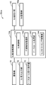
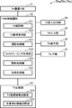
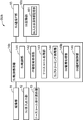
- FIG. 1 shows the structure of the monitoring subject monitoring assistance system in embodiment. It is a figure which shows the structure of the sensor apparatus of 1st Embodiment in the said to-be-monitored person monitoring assistance system. It is a figure which shows the structure of the management server apparatus of 1st Embodiment in the said to-be-monitored person monitoring assistance system. It is a figure which shows the structure of the information table between apparatuses memorize
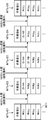
- FIG. It is a figure for demonstrating the transition of SV entry / exit status information table in the operation
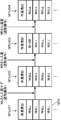
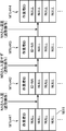
- FIG. It is a figure for demonstrating the SV entry / exit status information table as another example.
- it is a sequence diagram showing an operation related to event notification in the monitored person monitoring support system. It is a figure which shows an example of the standby screen displayed on the said portable terminal device. It is a figure which shows an example of the monitoring information screen displayed on the said portable terminal device. It is a figure which shows an example of the nurse call reception screen displayed on the said portable terminal device. It is a figure which shows the structure of the sensor apparatus of 2nd Embodiment in the said monitoring person monitoring assistance system.
- FIG. 1 It is a figure which shows the structure of the management server apparatus of 2nd Embodiment in the said monitoring person monitoring assistance system.
- it is a sequence diagram showing the operation of the second embodiment regarding the stop and release of notification in the monitored person monitoring support system.
- movement shown in FIG. It is a figure for demonstrating the transition of the SU entry / exit status information table in the operation
- it is a figure which shows the structure of the sensor apparatus of 3rd Embodiment in the said to-be-monitored person monitoring assistance system.
- FIG. 1 it is a sequence diagram which shows operation
- the monitored person monitoring support system in the embodiment is a system that supports monitoring of the monitored person by detecting and notifying a predetermined event related to the monitored person who is located in a predetermined monitoring area.
- a notification control unit, a management unit, a reading unit, and a generation unit controls the notification of the detection.
- the management unit manages first specifying information for specifying a predetermined worker. When the worker enters the monitoring area, the reading unit reads one of the first identification information of the worker and the second identification information that identifies the monitoring area.
- the generating unit has the other specific information of the first and second specific information in advance, and when the one specific information is read by the reading unit, the generation unit reads the other specific information and the reading unit.
- link information that links the one specific information to each other is generated, and the generated link information is notified to the management unit.
- the management unit manages the first identification information based on the association information notified from the generation unit, and the notification control unit is managed by the management unit.
- the detection in the monitoring area where the one specific information used when the linking information of the first specific information is generated by the generation unit is read by the reading unit. Stop notifications for.
- a monitored person monitoring support system includes a plurality of devices, that is, the sensor device SU, the identification device RD, the management server device SV, and the terminal devices SP and TA will be described more specifically.
- each of the notification control unit, the management unit, the reading unit, and the generation unit may be mounted on any of the plurality of devices.
- FIG. 1 is a diagram illustrating a configuration of a monitored person monitoring support system according to the embodiment. 1 shows not only the configuration of the monitored person monitoring support system MSa in the first embodiment but also the configuration of monitored person monitoring support systems MSb and MSc in the second and third embodiments described later.
- FIG. 2 is a diagram showing a configuration of the sensor device of the first embodiment in the monitored person monitoring support system.
- FIG. 3 is a diagram showing a configuration of the management server device of the first embodiment in the monitored person monitoring support system.
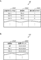
- FIG. 4 is a diagram showing a configuration of an inter-device information table stored in the management server device. 4A shows a configuration of a notification destination correspondence information table in the inter-device information table, and
- FIG. 4B shows a configuration of a communication address correspondence information table in the inter-device information table.
- FIG. 5 is a diagram illustrating a configuration of the mobile terminal device of the first embodiment in the monitored person monitoring support system.
- This monitored person monitoring support system MSa detects the monitored person (watched person) Ob (Ob-1 to Ob-3) that is the monitored object (watched object) to be monitored (monitored) and monitors the monitored object. For example, as shown in FIG. 1, one or a plurality of sensor devices SUa (SUa-1 to SUa-3) and one or a plurality of identification devices are monitored.
- ID device RDa (RDa-1 to RDa-3), management server device SVa, fixed terminal device SP, one or more portable terminal devices TAa (TAa-1, TAa-2), private branch exchange (PBX, Private branch exchange (CX), and wired (wireless) and network (network, communication line) NW such as LAN (Local Area Network) It is communicatively coupled to.
- the network NW may be provided with repeaters such as repeaters, bridges, and routers that relay communication signals.
- the plurality of sensor devices SUa-1 to SUa-3, the management server device SVa, the fixed terminal device SP, the plurality of portable terminal devices TAa-1, TAa-2, and the private branch exchange CX are L2 switches.
- a wired / wireless LAN for example, a LAN in accordance with the IEEE 802.11 standard
- NW including the LS and the access point AP.
- the plurality of sensor devices SUa-1 to SUa-3, the management server device SVa, the fixed terminal device SP, and the private branch exchange CX are connected to the line concentrator LS, and the plurality of portable terminal devices TAa-1, TAa-2. Is connected to the line concentrator LS via the access point AP.
- the network NW constitutes a so-called intranet by using Internet protocol groups such as TCP (Transmission control protocol) and IP (Internet protocol).
- the monitored person monitoring support system MSa is arranged at an appropriate place according to the monitored person Ob.
- the monitored person (person to be watched) Ob is, for example, a person who needs nursing due to illness or injury, a person who needs care due to a decrease in physical ability, a single person living alone, or the like.
- the monitored person Ob may be a person who needs the detection when a predetermined inconvenient event such as an abnormal state occurs in the person. preferable.
- the monitored person monitoring support system MSa is suitably arranged in a building such as a hospital, a welfare facility for the elderly, and a dwelling unit according to the type of the monitored person Ob.
- the monitored person monitoring support system MSa is disposed in a building of a care facility that includes a plurality of living rooms RM in which a plurality of monitored persons Ob live and a plurality of living rooms such as a nurse station. .
- the reading unit and the generation unit are provided in the mobile terminal device TAa, and the notification control unit and the management unit are provided in the management server device SVa. Is provided. More specific description will be given below.
- the private branch exchange (line switching machine) CX is connected to the network NW, performs extension telephone calls such as outgoing call, incoming call and telephone call between the portable terminal apparatuses TAa to carry out extension calls between the portable terminal apparatuses TAa, and For example, outgoing calls, incoming calls, and calls between the external telephone TL and the mobile terminal device TAa are connected to an external telephone TL such as a fixed telephone or a mobile telephone via a public telephone network PN such as a fixed telephone network or a mobile telephone network.
- PN public telephone network
- the private branch exchange CX is, for example, a digital exchange or an IP-PBX (Internet Protocol Private Branch eXchange).
- the ID device RDa is a device that is provided corresponding to the monitoring area where the monitored person Ob to be monitored is located, and includes second specifying information for specifying the monitoring area so as to be readable by the mobile terminal device TAa.
- Such an ID device RDa is, for example, a member having a one-dimensional code (bar code) or a two-dimensional code representing the second specifying information. More specifically, the ID device RDa is, for example, a plate on which a one-dimensional code (bar code) or a two-dimensional code representing the second specific information is printed, and is arranged in a monitoring area corresponding to the ID device RDa. Established.
- the monitoring area is an appropriate area according to the place where the monitored person monitoring support system MSa is disposed.
- the monitored person monitoring support system MSa is disposed in a building of a care facility.
- the monitoring area is a room RM of a care facility where the monitored person Ob is present. Therefore, each of the plurality of ID devices RDa-1 to RDa-3 is arranged in each of the plurality of living rooms RM-1 to RM-3.
- the monitoring area is a hospital room (hospital room) where the monitored person Ob is located, and for example, the monitored person monitoring
- the monitoring area is a room of the dwelling unit where the monitored person Ob is present.
- the living room is a so-called large room where a plurality of monitored persons Ob are located
- the monitoring area may be a predetermined area including the bedding used by the monitored person Ob.
- the monitoring area may be a predetermined area including the bedding used by the monitored person Ob in the living room of the dwelling unit.
- the second specifying information is, for example, a monitoring area identifier (monitoring area ID) that is an identifier for specifying and identifying the monitoring area.
- the monitoring area ID since the monitoring area is a room where the monitored person Ob is located, the monitoring area ID includes the room name, the room number, the monitored person name of the monitored person Ob located in the room RM, and It may be a predetermined code string such as a serial number.
- the sensor ID is an identifier for identifying and identifying the sensor device SUa. For this reason, in the present embodiment, the sensor ID is used as the second specifying information.
- the ID device RDa is a member having a one-dimensional code or a two-dimensional code representing the second specific information, but is not limited to this, and may be another device.
- the ID device RDb may be an IC card (RF tag) or a magnetic card that stores the second specific information.
- the ID device RDb may be a tablet terminal device that has a communication function and stores the second specific information.
- the sensor device SUa is provided corresponding to the monitoring area where the monitored person Ob to be monitored is located, and has a communication function for communicating with other devices SVa, SP, and TAa via the network NW.
- This is a device that detects a predetermined event (event) related to and notifies the management server device SVa.
- the predetermined event is preferably a predetermined event that needs to be dealt with.
- the predetermined event is a predetermined action and a nurse call set in advance in the monitored person Ob.
- the sensor device SUa detects a predetermined action in the monitored person Ob, notifies (transmits) the detection result to the management server device SVa as an example of the predetermined event, and accepts a nurse call. Then, the nurse call is notified (transmitted) to the management server device SVa as another example of the predetermined event, a voice call is performed with the terminal devices SP and TAa, and an image including a moving image is generated to generate the terminal device SP.
- a device that delivers moving images to TAa For example, as shown in FIG.
- the sensor device SUa includes an imaging unit 11, a sensor side sound input / output unit (SU sound input / output unit) 12, a nurse call reception operation unit 13, and a sensor side control process.
- the imaging unit 11 is an apparatus that is connected to the SU control processing unit 14a and generates an image (image data) under the control of the SU control processing unit 14a.
- the image includes a still image (still image data) and a moving image (moving image data).
- the imaging unit 11 is disposed so as to be able to monitor the monitoring area (in the example shown in FIG. 1, the room (room) RM of the installation location), images the monitoring area as an imaging target from above, and looks down on the imaging target.
- the generated image (image data) is generated, and the image to be captured (target image) is output to the SU control processing unit 14a.
- the imaging unit 11 is positioned when the head of the monitored person Ob is located in the bedding (for example, a bed) on which the monitored person Ob is lying. It arrange
- the sensor device SUa uses the imaging unit 11 to acquire an image of the monitored person Ob captured from above the monitored person Ob, preferably an image captured from directly above the planned head position.
- Such an imaging unit 11 may be, for example, a visible camera that generates a visible light image, but in the present embodiment, an infrared image is generated so that the monitored person Ob can be monitored even in a relatively dark place. It is an infrared camera.
- the SU sound input / output unit 12 is a circuit that inputs and outputs sound. That is, the SU sound input / output unit 12 is a circuit that is connected to the SU control processing unit 14a and generates and outputs a sound corresponding to an electric signal representing sound according to the control of the SU control processing unit 14a. It is a circuit for acquiring the sound of and inputting into the sensor apparatus SUa.
- the SU sound input / output unit 12 includes, for example, a speaker that converts a sound electrical signal (sound data) into a sound mechanical vibration signal (acoustic signal), and a microphone that converts a sound mechanical vibration signal in the audible region into an electrical signal. And so on.
- the SU sound input / output unit 12 outputs an electric signal representing an external sound to the SU control processing unit 14a, and also converts the electric signal input from the SU control processing unit 14a into a sound mechanical vibration signal and outputs the sound. .
- the nurse call reception operation unit 13 is connected to the SU control processing unit 14a and is a switch circuit such as a push button switch for inputting the nurse call to the sensor device SUa.
- the nurse call reception operation unit 13 may be connected to the SU control processing unit 14a by wire, or may be connected to the SU control processing unit 14a by the short-range wireless communication such as Bluetooth (registered trademark) standard, for example. .
- the SU communication IF unit 15 is a communication circuit that is connected to the SU control processing unit 14a and performs communication according to the control of the SU control processing unit 14a.
- the SU communication IF unit 15 generates a communication signal containing the data to be transferred input from the SU control processing unit 14a according to the communication protocol used in the network NW of the monitored person monitoring support system MSa.
- a communication signal is transmitted to other devices SVa, SP, and TAa via the network NW.
- the SU communication IF unit 15 receives communication signals from other devices SVa, SP, and TAa via the network NW, extracts data from the received communication signals, and can process the extracted data by the SU control processing unit 14a.
- the data is converted into a simple format and output to the SU control processing unit 14a.
- the SU communication IF unit 15 includes, for example, a communication interface circuit that complies with the IEEE 802.11 standard or the like.
- the SU storage unit 16a is a circuit that is connected to the SU control processing unit 14a and stores various predetermined programs and various predetermined data under the control of the SU control processing unit 14a.
- the various predetermined programs include, for example, predetermined SU control processing programs, and the SU control processing programs include, for example, the units 11 to 13, 15, 16a of the sensor device SUa according to the functions of the units.
- a SU control processing program for executing predetermined information processing related to monitoring of the monitored person Ob, and the like.
- a predetermined action in the monitored person Ob is detected, and a detection result is notified to the predetermined terminal devices SP and TAa via the management server device SVa as an example of the predetermined event.
- the behavior detection processing program or the nurse call reception operation unit 13 When a nurse call is received by the behavior detection processing program or the nurse call reception operation unit 13, the fact is notified to the predetermined terminal device SP, TAa via the management server device SVa as another example of the predetermined event,
- the nurse call processing program for performing a voice call with the terminal devices SP and TAa, or the moving image generated by the imaging unit 11 is sent to the terminal device SP and TAa that requested the moving image.
- a SU streaming processing program distributed by streaming is included.
- the various kinds of predetermined data include data necessary for executing each program such as the sensor ID of the own device and the communication address of the management server device SVa.
- the sensor ID is a predetermined code string such as a living room name, a living room number, a monitored person name of the monitored person Ob located in the living room RM, and a serial number. It may be.
- the SU storage unit 16a includes, for example, a ROM (Read Only Memory) that is a nonvolatile storage element, an EEPROM (Electrically Erasable Programmable Read Only Memory) that is a rewritable nonvolatile storage element, and the like.
- the SU storage unit 16a includes a RAM (Random Access Memory) serving as a working memory of the so-called SU control processing unit 14a that stores data generated during execution of the predetermined program.
- the SU control processing unit 14a controls each unit 11 to 13, 15, 16a of the sensor device SUa according to the function of each unit, and sends a predetermined event related to the monitored person Ob to the management server device SVa.
- This is a circuit for notification. More specifically, in the present embodiment, the SU control processing unit 14a detects a predetermined action in the monitored person Ob and notifies the management server device SVa of the detection result as an example of the predetermined event (notification, The nurse call is received, the nurse call is notified (notified and transmitted) to the management server device SVa as another example of the predetermined event, a voice call is performed between the terminal devices SP and TAa, and a moving image is transmitted.
- the SU control processing unit 14a includes, for example, a CPU (Central Processing Unit) and its peripheral circuits. By executing the SU control processing program, the SU control processing unit 14a performs a sensor side control unit (SU control unit) 141, a behavior detection processing unit 142, a nurse call processing unit 143, and a sensor side streaming processing unit ( SU streaming processing unit) 144 is functionally provided.
- SU control unit sensor side control unit
- a behavior detection processing unit 142 e.g., a nurse call processing unit
- a sensor side streaming processing unit SU streaming processing unit
- the SU control unit 141 controls each unit 11 to 13, 15, 16a of the sensor device SUa according to the function of each unit, and controls the entire control of the sensor device SUa.
- the SU control unit 141 counts the time in year / month / day / hour / minute / second.
- the behavior detection processing unit 142 detects a predetermined behavior preset in the monitored person Ob and notifies the management server device SVa of the detection result as an example of the predetermined event. More specifically, in the present embodiment, the predetermined action includes, for example, wake-up when the monitored person Ob occurred, leaving the monitored person Ob away from the bedding, falling down when the monitored person Ob fell from the bedding, And four actions of the fall where the monitored person Ob fell. Then, for example, the behavior detection processing unit 142 detects the head of the monitored person Ob based on the target image captured by the imaging unit 11, and detects the temporal change in the size of the detected head of the monitored person Ob. Based on this, the rising, leaving, falling, and falling of the monitored person Ob are detected.
- the first to third threshold values Th1 to Th3 are stored in advance in the SU storage unit 16a as one of the various predetermined data in the area where the bedding BD is located.
- the first threshold value Th1 is a threshold value for identifying the size of the head in the lying posture and the size of the head in the sitting posture in the region where the bedding BD is located.
- the second threshold Th2 is a threshold for identifying whether or not the head is in the standing posture in the living room RM excluding the location area of the bedding BD.
- the third threshold value Th3 is a threshold value for identifying whether or not the size is the size of the head of the lying posture in the living room RM excluding the location area of the bedding BD.
- the action detection process part 142 extracts a moving body area
- the behavior detection processing unit 142 uses, for example, a circular or elliptical Hough transform from the extracted moving object region, for example, by pattern matching using a head model prepared in advance, or for example, for head detection.
- the head region of the monitored person Ob is extracted by the neural network learned in step (b). And the action detection process part 142 detects awakening, getting out of bed, falling, and falling from the position and magnitude
- the behavior detection processing unit 142 determines that the position of the extracted head is within the region where the bedding BD is located, and the size of the extracted head uses the first threshold Th1 to determine the size of the lying posture.
- the time changes from the sitting posture to the size of the sitting posture it is determined that the user gets up and the rising is detected.
- the behavior detection processing unit 142 is a case where the position of the extracted head changes over time from the location of the bedding BD to the outside of the location of the bedding, and the size of the extracted head is the second size.
- Th2 is changed from a certain size to the size of the standing posture by using the threshold Th2
- the behavior detection processing unit 142 is a case where the position of the extracted head changes over time from the location where the bedding BD is located to the outside of the location where the bedding BD is located, and the size of the extracted head is the first size.
- the behavior detection processing unit 142 uses the third threshold value Th3 when the extracted head position is in the room RM excluding the location area of the bedding BD and the extracted head size is the third threshold Th3.
- the time changes from the size to the size of the recumbent posture it is determined that the vehicle has fallen, and the fall is detected.
- the behavior detection processing unit 142 When the predetermined behavior is detected in this way, the behavior detection processing unit 142 notifies the event containing event information (event information) representing the content of the predetermined event (phenomenon) related to the monitored person Ob.
- Communication signal (first event notification communication signal) is notified to the management server device SVa by the SU communication IF unit 15. More specifically, the behavior detection processing unit 142 transmits a first event notification communication signal containing the sensor ID of the own device, event information indicating the content of the event, and a target image used for detection of the predetermined behavior, to the SU.
- the data is transmitted to the management server device SVa via the communication IF unit 15.
- the event information is one or more of getting up, getting out of bed, falling, falling, and nurse call (NC).
- the behavior detection processing unit 142 detects the rising, leaving, falling, and One or more of the falls are accommodated in the first event notification communication signal as the event information.
- the image may be at least one of a still image and a moving image.
- the still image is notified, and the moving image is distributed in response to an operator's request.
- a moving image may be distributed, a still image and a moving image may be transmitted, and the still image and the moving image may be displayed on the terminal devices SP and TAa by screen division.
- the nurse call processing unit 143 notifies the management server device SVa of the first event notification communication signal accommodated as another example of the predetermined event when the nurse call reception operation unit 13 receives the nurse call.
- a voice call is performed with the terminal devices SP and TAa. More specifically, when the nurse call reception operation unit 13 is input and operated, the nurse call processing unit 143 transmits the first event notification communication signal containing the nurse call as the sensor ID of the own device and the event information as the SU communication.
- the data is transmitted to the management server device SVa via the IF unit 15.
- the nurse call processing unit 143 uses the SU sound input / output unit 12 or the like to make a voice call with the terminal devices SP and TAa by, for example, VoIP (Voice over Internet Protocol).
- VoIP Voice over Internet Protocol
- the SU streaming processing unit 144 receives the request from the fixed terminal device SP or the mobile terminal device TAa.
- the moving image generated by the imaging unit 11 (for example, a live moving image) is distributed via the SU communication IF unit 15 by streaming reproduction.
- FIG. 1 shows, as an example, first to third sensor devices SUa-1 to SUa-3, and the first sensor device SUa-1 together with the first ID device RDa-1 is the monitored person Ob.
- the second sensor device SUa-2 is arranged in the room RM-1 (not shown) of Mr.
- a Ob-1 who is one person and the second sensor device SUa-2 is one of the monitored persons Ob together with the second ID device RDa-2.
- the third sensor device SUa-3, together with the third ID device RDa-3 is the room of Mr.
- C Ob-3 one of the monitored persons Ob It is disposed in RM-3 (not shown).
- the fixed terminal device SP includes a communication function for communicating with other devices SUa, SVa, and TAa via the network NW, a display function for displaying predetermined information, an input function for inputting predetermined instructions and data, and the like.
- An operator interface of the monitored person monitoring support system MSa by inputting a predetermined instruction or data to be given to the management server SVa or the portable terminal device TAa or displaying monitoring information obtained by the sensor device SUa.
- It is a device that functions as (UI).
- Such a fixed terminal device SP can be configured by, for example, a computer with a communication function.
- the fixed terminal device SP as an example of the terminal device operates in the same manner as the mobile terminal device TAa. However, in this specification, the mobile terminal device TAa which is another example of the terminal device will be described.
- the mobile terminal device TAa has a communication function for communicating with other devices SVa, SP, and SUa via the network NW, a display function for displaying predetermined information, an input function for inputting predetermined instructions and data, and a voice call. It has a calling function to perform, inputs a predetermined instruction or data to be given to the management server device SVa and the sensor device SUa, displays monitoring information obtained by the sensor device SUa by a notification from the management server device SVa, This is a device for answering a nurse call or calling out by a voice call with the device SUa.
- the portable terminal device TAa has in advance first specifying information for specifying a predetermined worker NS, and the second specifying information (in this embodiment, a monitoring area ID (sensor ID)) is an ID device.
- the linking information read from the RDa and linking the first specifying information and the second specifying information is generated, and the generated linking information is notified to the management server device SVa.
- the first specific information is, for example, a worker identifier (worker ID) that is an identifier for identifying and identifying the worker NS.
- the worker ID is, for example, a predetermined code string such as a worker name, a staff number, and a serial number.
- the worker NS is a person who performs a predetermined job, and is an appropriate person according to the place where the monitored person monitoring support system MSa is installed. More specifically, the worker NS mainly includes a doctor and a nurse who perform each work such as medical care and nursing on the patient when the monitored person Ob is a patient, and the monitored person Ob. They are a caregiver who performs care work for the care recipient when he is a caregiver, a nutritionist who performs honor management work such as the patient and the care recipient, and a person who performs work such as cleaning.
- such a portable terminal device TAa includes a terminal-side communication interface unit (TA communication IF unit) 31, a terminal-side control processing unit (TA control processing unit) 32, and A terminal side storage unit (TA storage unit) 33, a terminal side sound input / output unit (TA sound input / output unit) 34, a terminal side input unit (TA input unit) 35, and a terminal side display unit (TA display unit). 36 and a terminal-side interface unit (TAIF unit) 37.
- the TA sound input / output unit 34 is connected to the TA control processing unit 32, and is a circuit for acquiring external sound and inputting it to the mobile terminal device TAa. It is a circuit for generating and outputting a sound corresponding to an electrical signal representing a sound according to the control of the processing unit 32.
- the TA input unit 35 is connected to the TA control processing unit 32 and is, for example, a circuit that accepts a predetermined operation and inputs it to the mobile terminal device TAa, such as a plurality of input switches assigned with a predetermined function.
- the predetermined operation include an operation of inputting a worker ID for logging in, a request operation for voice call and its end operation, a request operation for live video and its end operation, and the notified event.
- Various operations necessary for monitoring such as an input operation indicating that there is an intention to perform (response, response) such as lifesaving, nursing, nursing care and assistance for the monitored person Ob related to the Etc. are included.
- the TA display unit 36 is connected to the TA control processing unit 32, and is monitored by a predetermined operation content input from the TA input unit 35 or the monitored person monitoring support system MSa according to the control of the TA control processing unit 32.
- the monitoring information related to the monitoring of the monitored person Ob for example, the predetermined event (the type of the predetermined action detected by the sensor device SUa or the nurse call received by the sensor device SUa), the image (still image and moving image) of the monitored person Ob ), The time when the notification is received, and the like, and display devices such as an LCD (Liquid Crystal Display) and an organic EL display.
- the TA input unit 35 and the TA display unit 36 constitute a touch panel.
- the TA input unit 35 is a position input device that detects and inputs an operation position such as a resistance film method or a capacitance method.
- a position input device is provided on the display surface of the TA display unit 36, and one or more input content candidates that can be input are displayed on the TA display unit 36.
- an operator such as a nurse or a caregiver (User)
- NS touches the display position where the input content to be input is displayed the position is detected by the position input device, and the display content displayed at the detected position is the portable terminal as the operation input content of worker NS Input to the device TAa.
- the TAIF unit 37 is a circuit that is connected to the TA control processing unit 32 and performs data input / output with an external device under the control of the TA control processing unit 32.
- the TAIF unit 37 is, for example, an interface circuit that performs short-range wireless communication such as an interface circuit that uses the Bluetooth (registered trademark) standard, an interface circuit that performs infrared communication such as the IrDA standard, and an interface circuit that uses the USB standard. is there.
- the TA communication IF unit 31 is a communication circuit that is connected to the TA control processing unit 32 and performs communication according to the control of the TA control processing unit 32, similarly to the SU communication IF unit 15.
- the TA communication IF unit 31 includes, for example, a communication interface circuit that conforms to the IEEE 802.11 standard or the like.
- the TA storage unit 33 is a circuit that is connected to the TA control processing unit 32 and stores various predetermined programs and various predetermined data under the control of the TA control processing unit 32.
- the various predetermined programs include, for example, a predetermined TA control processing program, and the TA control processing program includes, for example, the units 31, 33 to 37 of the mobile terminal device TAa according to the functions of the units.
- a TA control program for performing control, a TA monitoring processing program for executing predetermined information processing relating to monitoring of the monitored person Ob, such as storage of monitoring information and display of the monitoring information, and a TA sound input / output unit 34 are used.
- a call processing program for making a voice call with the sensor device SUa a TA streaming processing program for receiving distribution of moving images from the sensor device SUa, and displaying the received moving images on the TA display unit 36 by streaming playback
- the front of the ID device RDa provided corresponding to the monitoring area
- the first specific information of the worker NS stored in advance and the read processing program
- a generation processing program that generates link information that links the read second specific information to each other and notifies the management server device SVa of the generated link information is included.
- the various kinds of predetermined data include the terminal ID of the own device, the other specific information of the first and second specific information of the own device (the first specific information in the present embodiment, more specifically work).
- (Person ID) screen information displayed on the TA display unit 36, the monitoring information of the monitored person Ob, sensor information related to the sensor device SUa, and other data necessary for executing each program.
- the terminal ID (terminal identifier) is an identifier for identifying and identifying the terminal devices SP and TAa, and is, for example, a predetermined code string such as a terminal device name and a serial number.
- the terminal ID and the worker ID may be the same or different.
- the TA storage unit 33 includes, for example, a ROM, an EEPROM, a RAM, and the like. In order to store each of the monitoring information and the first specific information (worker ID in the present embodiment), the TA storage unit 33 includes a terminal-side monitoring information storage unit (TA monitoring information storage unit) 331 and worker ID information.
- the TA monitoring information storage unit 331 stores monitoring information of the monitored person Ob.
- the TA monitoring information storage unit 331 uses, as the monitoring information, the sensor ID and event information (event information, this implementation) accommodated in the second event notification communication signal received from the management server device SVa as described later.
- the communication address of the sensor device SUa that is the download destination of the image and the moving image, the reception time of the second event notification communication signal, the presence or absence of countermeasures, and the like are associated with each other.
- the worker ID information storage unit 332 stores first identification information for identifying the worker NS, in this embodiment, the worker ID.
- the worker ID may be registered in advance in the portable terminal device TAa and stored in the worker ID information storage unit 332, or may be input from the TA input unit 35 at the time of login, for example, and stored in the worker ID information storage. It may be stored in the part 332.
- the TA control processing unit 32 controls each unit 31, 33 to 37 of the mobile terminal device TAa according to the function of each unit, receives and displays the monitoring information of the monitored person Ob, and responds to the nurse call and voice This is a circuit for applying.
- the TA control processing unit 32 generates the association information and notifies the management server device SVa when the second specific information of the monitoring area is read.
- the TA control processing unit 32 includes, for example, a CPU and its peripheral circuits.
- the TA control processing unit 32 executes a terminal control unit (TA control unit) 321, a terminal side monitoring processing unit (TA monitoring processing unit) 322, a call processing unit 323, and terminal side streaming by executing a TA control processing program.
- a processing unit (TA streaming processing unit) 324, a reading processing unit 325, and a generation processing unit 326 are functionally provided.
- the TA control unit 321 controls the respective units 31 and 33 to 37 of the mobile terminal device TAa according to the functions of the respective units, and governs overall control of the mobile terminal device TAa.
- the TA control unit 321 measures time by year / month / day / hour / minute / second.
- the TA monitoring processing unit 322 executes predetermined information processing related to monitoring of the monitored person Ob. More specifically, when the TA monitoring processing unit 322 receives the second event notification communication signal transmitted by the management server device SVa due to the first event notification communication signal transmitted by the sensor device SUa. The monitoring information of the monitored person Ob is stored (recorded) in the TA monitoring information storage unit 331 based on each information (each data) accommodated in the received second event notification communication signal. The TA monitoring processing unit 322 displays a screen corresponding to each piece of information contained in the received second event notification communication signal on the TA display unit 36. Then, when receiving a predetermined input operation from the TA input unit 35, the TA monitoring processing unit 322 executes a predetermined process corresponding to the input operation.
- the call processing unit 323 performs a voice call with the sensor device SUa by using the TA sound input / output unit 34 or the like. More specifically, for example, the call processing unit 323 uses the TA sound input / output unit 34 and the like to transmit the first event notification communication signal that causes the transmission of the second event notification communication signal to the management server device SVa. For example, VoIP is performed with the transmission source sensor device SUa.
- the TA streaming processing unit 324 receives distribution of a moving image from the sensor device SUa, and displays the distributed moving image on the TA display unit 36 by streaming reproduction.
- the reading processing unit 325 reads one specific information of the first specific information of the worker NS and the second specific information for specifying the monitoring region when the worker NS enters the monitoring region. is there. In the present embodiment, when the worker NS enters the monitoring area, the reading processing unit 325 reads the second specific information of the monitoring area from the ID device RDa provided corresponding to the monitoring area.
- the portable terminal device TAa since the ID device RDa is a plate on which a one-dimensional code or a two-dimensional code representing a sensor ID is printed as a monitoring area ID, the portable terminal device TAa further includes a camera, for example, and the reading processing unit 325 , By performing predetermined image processing on an image (image data) obtained by imaging the one-dimensional code or the two-dimensional code with the camera, the one-dimensional code or the two-dimensional code is identified and analyzed, The second specific information (sensor ID) is read from the analysis result.
- the portable terminal device TAa further includes a card reader of the IC card (RF tag) or the magnetic card, and the reading processing unit 325
- the second specific information (sensor ID) is read from an IC card (RF tag) or a magnetic card with a card reader.
- the reading processing unit 325 reads the second specific information (sensor ID) from the tablet terminal device by the TAIF unit 37.
- the generation processing unit 326 associates the other specific information with the one specific information read by the reading processing unit 325. And the generated association information is notified to the management server device SVa.
- the generation processing unit 326 reads the second identification information of the monitoring area by the reading processing unit 325, and the first identification of the worker NS stored in advance in the worker ID information storage unit 332 is performed. Association information is generated by associating the information with the second specific information of the monitoring area read by the reading processing unit 325, and the generated association information is notified to the management server device SVa.
- Such a portable terminal device TA can be configured by a portable communication terminal device such as a so-called tablet computer, a smartphone, or a mobile phone.
- the management server device SVa has a communication function for communicating with other devices SUa, SP, and TAa via the network NW.
- the management server device SVa is provided with information related to monitoring the monitored person Ob ( Monitoring information (in this embodiment, for example, the predetermined event (a predetermined action type detected by the sensor device SUa or a nurse call received by the sensor device SUa), an image (still image and moving image) of the monitored person Ob, and The time when the notification is received) is managed, the predetermined event is notified (re-notification, re-notification, transmission) to the predetermined terminal device SP, TAa, and the client (the terminal device SP, TAa, etc. in this embodiment).
- Monitoring information in this embodiment, for example, the predetermined event (a predetermined action type detected by the sensor device SUa or a nurse call received by the sensor device SUa), an image (still image and moving image) of the monitored person Ob, and The time when the notification is received) is managed, the predetermined event is notified (re-
- the management server device SVa manages the first specific information (worker ID in this embodiment) based on the association information notified from the mobile terminal device TAa, and the predetermined event. Is notified to the predetermined terminal device SP, TAa (re-notification, re-notification, transmission), the detection notification is controlled based on the management result.
- the management server device SVa includes a server-side communication interface unit (SV communication IF unit) 21, a server-side control processing unit (SV control processing unit) 22a, and a server-side storage unit. (SV storage unit) 23a.
- the SV communication IF unit 21 is a communication circuit that is connected to the SV control processing unit 22a and performs communication according to the control of the SV control processing unit 22a.
- the SV communication IF unit 21 includes, for example, a communication interface circuit that complies with the IEEE 802.11 standard or the like.
- the SV storage unit 23a is a circuit that is connected to the SV control processing unit 22a and stores various predetermined programs and various predetermined data in accordance with the control of the SV control processing unit 22a.
- the various predetermined programs include, for example, predetermined SV control processing programs, and the SV control processing program controls, for example, the units 21 and 23a of the management server device SVa according to the functions of the units.
- the first specific information (in the present embodiment) based on the SV control program to be executed, the SV monitoring processing program for executing predetermined information processing related to the monitoring of the monitored person Ob, and the association information notified from the portable terminal device TAa.
- the various kinds of predetermined data include the server ID of the own device, the monitoring information of the monitored person Ob, the inter-device information indicating information between the devices SUa, SP, and TAa such as the notification destination of the predetermined event, the sensor device Data necessary for executing each program such as sensor information related to SUa and SV entry / exit status information indicating the entry / exit status of the worker NS with respect to the monitoring area are included.
- the server ID is an identifier for identifying the management server device SVa and identifying the management server device SVa, and is, for example, a predetermined code string such as a management server device name and a serial number.
- the SV storage unit 23a includes, for example, a ROM, an EEPROM, a RAM, and the like.
- the SV storage unit 23a may further include a relatively large capacity hard disk device (HDD) as necessary.
- HDD hard disk device
- SV storage part 23a is server side monitoring information storage part (SV monitoring information storage part) 231, Inter-apparatus information storage part 232, a sensor information storage unit 233, and a server side entry / exit status information storage unit (SV entry / exit status information storage unit) 234 are functionally provided.
- the SV monitoring information storage unit 231 stores monitoring information of the monitored person Ob transmitted / received to / from each of the devices SUa, SP, and TAa. More specifically, in the SV monitoring information storage unit 231, in this embodiment, as the monitoring information, the sensor ID and the event information are based on each information accommodated in a communication signal such as a first event notification communication signal.
- Event information in this embodiment, getting up, getting out of bed, falling, falling and nurse call), reception time, target image (still image and moving image), presence / absence of correspondence (presence / absence of corresponding reception), etc. are stored in association with each other.
- the inter-device information storage unit 232 stores notification destination correspondence information, communication address correspondence information and the like as the inter-device information.
- the notification destination correspondence information includes a sensor ID and a notification destination (sender) indicating a notification destination (re-notification destination, re-notification destination, transmission destination) such as a first event notification communication signal transmitted from the sensor device SUa. This is information indicating the correspondence relationship between the terminal ID that is the re-notification destination) and the correspondence relationship between the sensor ID that is the transmission source and the notification permission / rejection flag indicating whether the notification to the notification destination is permitted.
- the communication address correspondence information is information representing IDs (sensor IDs, terminal IDs) of the devices SUa, SP, and TAa and their communication addresses.
- the notification destination correspondence information table AT for registering the notification destination correspondence information includes, for example, a transmission source field 2321 for registering the sensor ID of the transmission source sensor device SUa and a transmission source field 2321 as illustrated in FIG. 4A.
- a notification permission flag field 2323 for registering a notification permission flag indicating whether or not notification (transmission) to a transmission destination corresponding to the sensor device SUa having the sensor ID is permitted, and sensor ID (sensor device SUa, Each monitoring area ID and monitoring area) has a record.
- the notification permission / refusal flag “0” represents permission of notification (cancel notification stop), and “1” represents notification disapproval (notification of notification). By default, “0” is registered in the notification permission / denial flag field.
- the communication address correspondence information table DT for registering the communication address correspondence information is a device ID field for registering device IDs (sensor IDs, terminal IDs) of the devices SUa, SP, and TAa as shown in FIG. 4B, for example. 2323 and a communication address field 2324 for registering the communication address of each device SUa, SP, TAa having the device ID registered in the device ID field 2323, for each device ID (each device SUa, SP, TAa). Provide a record.
- the sensor information storage unit 233 stores sensor information that is information related to the sensor device SUa.
- the sensor information includes, for example, the sensor ID of the sensor device SUa, the location (monitoring area) where the sensor device SUa is located, and the object located in the location (monitoring area) where the sensor device SUa is located. This is information in which the name of the monitored person of the monitoring person Ob is associated with each other.
- the SV entry / exit status information storage unit 234 stores the SV entry / exit status information indicating the entry / exit status of the worker NS with respect to the monitoring area.
- the SV entry / exit status information represents the entry / exit status of the worker NS with respect to the monitoring area by the presence / absence of storage of the first specific information, in this embodiment, the worker ID.
- the monitoring area is a plurality of living rooms RM. Therefore, for each monitoring area, a plurality of pieces of second specifying information are used to represent the entry / exit status of the worker NS with respect to the monitoring area.
- the monitoring area ID i.e., sensor ID
- the monitoring area ID is associated with the first specific information, in this embodiment, the worker ID, and stored in the SV entry / exit situation information storage unit 234 as the SV entry / exit situation information. Is done. More specifically, the SV entry / exit status information is stored in the SV entry / exit status information storage unit 234 in a table format.
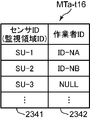
- the SV entry / exit status information table MTa for registering the SV entry / exit status information includes, for example, a sensor ID field 2341 for registering a sensor ID and sensors registered in the sensor ID field 2341 as shown in FIGS.
- a worker ID field 2342 for registering the worker ID of the worker NS who enters and leaves the monitoring region corresponding to the sensor device SUa having the ID, for each sensor ID (that is, the monitoring region (monitoring region ID)).
- Sensor ID that is, the monitoring region (monitoring region ID)
- sensor IDs of a plurality of monitoring areas (rooms RM) are registered in advance.
- the SV control processing unit 22a controls each unit 21 and 23a of the management server device SVa according to the function of each unit, and receives notification of the predetermined event from the sensor device SUa, monitoring related to monitoring of the monitored person Ob Information management is performed, the predetermined event is notified (re-notification, re-notification, transmission) to the predetermined terminal device SP, TAa, data corresponding to a client request is provided to the client, and a monitored person monitoring support system This is a circuit for managing the entire MSa.
- the SV control processing unit 22a manages the first specific information (worker ID in the present embodiment) based on the association information notified from the portable terminal device TAa, and the predetermined information When the event is notified (re-notification, re-notification, transmission) to the predetermined terminal device SP and TAa, the detection notification is controlled based on the management result.
- the SV control processing unit 22a includes, for example, a CPU and its peripheral circuits.
- the SV control processing unit 22a executes a server control unit (SV control unit) 221, a server side monitoring processing unit (SV monitoring processing unit) 222, and a server side notification control unit (SV) by executing the SV control processing program.
- the SV control unit 221 controls the respective units 21 and 23a of the management server device SVa according to the functions of the respective units, and governs overall control of the management server device SVa.
- the SV control unit 221 counts the year / month / day / hour / minute / second.
- the SV management processing unit 224a manages the first specific information of the worker NS. More specifically, the SV management processing unit 224a manages the first specific information of the worker NS based on the association information notified from the mobile terminal device TAa. In this embodiment, the management processing unit 224a, when the association information of the first specific information that has already been managed is further notified from the mobile terminal device TAa, the first management that has already been managed. Cancel management of specific information.
- the SV management processing unit 224a first determines the sensor ID as the second specific information in the notified association information, A record to be registered (searched) in the sensor ID field 2341 of the SV entry / exit status information table MTa stored in the SV entry / exit status information storage unit 234 is selected. Next, the SV management processing unit 224a checks whether or not the worker ID as the first specific information in the notified association information is registered in the worker ID field 2342 in the selected record. If the worker ID of the notified association information is not registered in the worker ID field 2342 in the selected record, the SV management processing unit 224a stores the worker ID field 2342 in the selected record.
- the SV entry / exit status information storage unit 234 stores the situation in which the worker NS having the worker ID enters (enters, stays in) the monitoring area in which the sensor device SUa having the sensor ID is provided.
- the SV management processing unit 224a displays the worker ID field in the selected record.
- the operator ID is deleted (erased) from 2342.
- the situation in which the worker NS having the worker ID has left (leaving out, absent) from the monitoring area provided with the sensor device SUa having the sensor ID is stored in the SV entry / exit status information storage unit 234.
- the SV management processing unit 224a manages the entry / exit status of the worker NS with respect to the monitoring area, depending on whether or not the worker ID is stored for each sensor ID (each monitoring area).
- the SV notification control unit 223a controls the detection notification. More specifically, the SV notification control unit 223a controls the notification of the detection based on the management result of the SV management processing unit 224a. In the present embodiment, the SV notification control unit 223a stores in the inter-device information storage unit 232 depending on whether or not the worker ID managed for each sensor ID (each monitoring area) is stored in the SV management processing unit 224a. The notification of detection is controlled by updating the notification permission / refusal flag in the stored notification destination correspondence information table AT.
- the SV notification control unit for each record in the SV entry / exit status information table MTa is updated by the SV management processing unit 224a.
- the sensor 223a stores the sensor ID registered in the sensor ID field 2341 of the record in the inter-device information storage unit 232.
- a record to be registered in the transmission source field (sensor ID field) 2321 in the notification destination correspondence information table AT is selected (searched) from the notification destination correspondence information table AT, and a notification permission flag of the selected record In the field 2323, the notification permission flag “1” is registered, while the SV notification
- the control unit 223a stores the sensor ID registered in the sensor ID field 2341 of the record in the inter-device information storage unit 232.
- a record to be registered in the transmission source field (sensor ID field) 2321 in the notification destination correspondence information table AT is selected (searched) from the notification destination correspondence information table AT, and a notification permission flag of the selected record The notification permission flag “0” is registered in the field 2323.
- the process is executed for each record of the SV entry / exit status information table MTa. However, the process may be executed only for the notification permission flag corresponding to the sensor ID of the updated record.
- the SV notification control unit 223a generates the association information of the first specific information when there is the first specific information (worker ID in the present embodiment) managed by the management processing unit 224a.
- the notification of the detection in the monitoring area in which the one specific information (sensor ID (monitoring area ID) in this embodiment) used in the generation by the unit 326 is read by the reading processing unit 325 is stopped.
- the SV notification control unit 223a includes the first specific information that has been no longer managed.
- the one specific information used when generating the association information by the generation processing unit 326 In the present embodiment, the detection information in the monitoring area obtained by reading the sensor ID (monitoring area ID) by the reading processing unit 325 is used. Cancel suspension of notification.
- the SV monitoring processing unit 222 When the SV monitoring processing unit 222 receives the notification of the predetermined event from the sensor device SUa, the SV monitoring processing unit 222 manages monitoring information regarding monitoring of the monitored person Ob, and based on the notification permission / denial flag stored in the inter-device information storage unit 232 The predetermined event is notified to predetermined terminal devices SP and TAa.
- the SV monitoring processing unit 222 receives the first event notification communication signal from the sensor device SUa, the monitoring related to monitoring of the monitored person Ob contained in the received first event notification communication signal. Information is stored (recorded) in the SV monitoring information storage unit 231.
- the SV monitoring processing unit 222 indicates the notification destination (re-notification destination, transfer destination, transmission destination) and notification permission / inhibition flag corresponding to the sensor device SUa that has transmitted the received first event notification communication signal, and the inter-device information storage unit 232.
- the SV communication IF unit 21 transmits the second event notification communication signal.
- the SV monitoring processing unit 222 first extracts a sensor ID accommodated in the received first event notification communication signal, and records a record for registering the extracted sensor ID in the transmission source field 2321 as a notification destination. Selection (search) is performed from the correspondence relationship information table AT, and the terminal ID of the notification destination and the notification permission / refusal flag are extracted from the notification destination field 2322 and the notification permission / refusal flag field 2323 in the selected record. When the extracted notification permission / refusal flag is “1”, the SV monitoring processing unit 222 ends the process without generating the second event notification communication signal.
- the SV monitoring processing unit 222 sends the second event notification communication signal to the terminal devices SP and TAa having the terminal ID of the extracted notification destination. And the SV communication IF unit 21 transmits the generated second event notification communication signal.
- the event information accommodated in the first event notification communication signal is the predetermined action (one or more of getting up, getting out of bed, falling and falling)
- the second event notification communication signal includes The communication address corresponding to the sensor device SUa having the sensor ID accommodated in the first event notification communication signal is accommodated as the download destination of the sensor ID, the event information and the target image, and the moving image accommodated in the one event notification communication signal. Is done.
- This communication address is selected (searched) from communication address correspondence information based on the sensor ID corresponding to the sensor device SUa that has transmitted the received first event notification communication signal.
- the event information accommodated in the first event notification communication signal is the nurse call
- the second event notification communication signal includes the sensor ID and event information accommodated in the first event notification communication signal. Is done.
- the management server device SVa is connected to the SV control processing unit 22a as necessary by a server side input unit (SV input unit) for inputting, for example, various commands and various data, as indicated by broken lines in FIG. 24)
- Server side output unit (SV output unit) 25 that outputs various commands and various data input by the SV input unit 24 and monitoring information related to monitoring of the monitored person Ob, and data between external devices
- a server-side interface unit (SVIF unit) 26 or the like for performing input / output may be provided.
- Such a management server device SVa can be configured by a computer with a communication function, for example.
- the management server device SVa corresponds to an example of a central management device.
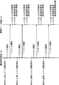
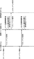
- FIG. 6 is a sequence diagram showing the operation of the first embodiment relating to the stop and release of notification in the monitored person monitoring support system as an example.
- FIG. 7 is a diagram for explaining the transition of the SV entry / exit status information table in the operation shown in FIG.
- FIG. 7 shows the SU entry / exit status information tables MTa-t11, MTa-t12, MTa-t13, MTa-t14 at time t11, time t12, time t13, time t14, and time t15 in order from the left side to the right side.
- MTa-15 is shown.
- FIG. 8 is a diagram for explaining an SV entry / exit status information table as another example.
- FIG. 8 is a diagram for explaining an SV entry / exit status information table as another example.
- FIG. 9 is a sequence diagram showing an operation related to event notification in the monitored person monitoring support system as an example.
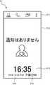
- FIG. 10 is a diagram illustrating an example of a standby screen displayed on the mobile terminal device.
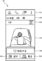
- FIG. 11 is a diagram illustrating an example of a monitoring information screen displayed on the mobile terminal device.
- FIG. 12 is a diagram illustrating an example of a nurse call reception screen displayed on the mobile terminal device.
- each of the devices SUa, RDa, SVa, SP, and TAa performs initialization of necessary units and starts operation when the power is turned on.
- the SU control processing unit 14a is functionally configured with a SU control unit 141, a behavior detection processing unit 142, a nurse call processing unit 143, and a SU streaming processing unit 144.
- the In the management server device SVa by executing the SV control processing program, the SV control processing unit 22a includes the SV control unit 221, the SV monitoring processing unit 222, the SV notification control unit 223a, and the SV management processing unit 224a.
- TA control processing unit 32 includes TA control unit 321, TA monitoring processing unit 322, call processing unit 323, TA streaming processing unit 324, reading processing unit. 325 and the generation processing unit 326 are functionally configured.
- the portable terminal device TAa-1 is assigned the worker ID by the worker NS-1 who carries the portable terminal device TAa-1 at the time of login operation, for example.
- ID-NA is input, worker ID; "ID-NA” is stored in advance, and the portable terminal device TAa-2 carries the portable terminal device TAa-2, for example, at the time of a login operation. It is assumed that worker ID; “ID-NB” is input by worker NS-2, and worker ID; “ID-NB” is stored in advance.
- the SV entering / exiting status information table MTa-t11 stored in the SV entering / exiting status information storage unit 234 includes As shown on the left side of FIG. 7, it is assumed that the operator ID is not registered (stored) in the record for registering the sensor ID; “SU-1” in the sensor ID field 2341.
- the worker NS- 1 In the operation of the first embodiment relating to the stop and release of the notification, in FIG. 6, for example, by the notification of a predetermined event, according to, for example, a nursing plan or a care plan, or, for example, in a cleaning operation, the worker NS- 1.
- the portable terminal device TAa-1 carried by the person is provided corresponding to the room RM-1
- the reading operation for reading the sensor ID is performed near the ID device RDa-1 (C111).
- the portable terminal device TAa-1 and the ID device RDa-1 are brought close to each other, the portable terminal device TAa-1 is second identified from the ID device RDa-1 by the reading processing unit 325 of the TA control processing unit 32.
- Sensor ID; “SU-1” is read as information (C112).
- the portable terminal device TAa-1 extracts the worker ID; “ID-NA” stored in the worker ID information storage unit 332 of the TA storage unit 33 by the generation processing unit 326 and reads it in the process C112.
- the sensor ID read by the processing unit 325; “SU-1” and the extracted worker ID; “ID-NA” are linked to each other to generate linking information, and a communication signal that contains this linking information (
- the first ID notification communication signal is generated for the management server device SVa, and the generated first ID notification communication signal is transmitted by the TA communication IF unit 31 (C113).
- the management server device SVa Upon receiving the first ID notification communication signal from the portable terminal device TAa-1, the management server device SVa uses the SV management processing unit 224a of the SV control processing unit 22a to process the entry / exit status of the worker NS with respect to the living room RM. Then, the operator ID “ID-NA” in the association information transmitted from the portable terminal device TAa-1 is managed (C114). More specifically, the SV management processing unit 224a first sets the sensor ID; “SU-1” as the second identification information in the association information contained in the received first ID notification communication signal; A record to be registered (searched) in the sensor ID field 2341 of the SV entry / exit status information table MTa stored in the information storage unit 234 is selected.
- the SV management processing unit 224a stores in the worker ID field 2342 in the selected record the worker ID as the first specifying information in the association information accommodated in the received first ID notification communication signal; Check whether “-NA” is registered.
- the SV management processing unit 224a performs the worker ID field 2342 in the selected record.
- the received worker ID; “ID-NA” is registered.
- the SV management processing unit 224a performs the worker ID in the selected record.
- the worker ID is deleted (erased) from the field 2342.
- the information is stored in the SV entry / exit status information storage unit 234.
- the received association information is stored in the operator ID field 2342 of the record in which the sensor ID of the received association information; “SU-1” is registered in the sensor ID field 2341. Since the worker ID; “ID-NA” is not registered, the SV management processing unit 224a registers the received worker ID; “ID-NA” in the worker ID field 2342.
- the SV entry / exit status information table MTa-t11 shown on the left side of FIG.
- the SU entry / exit status information table MTa-t12 in which the worker ID; “ID-NA” is registered in the worker ID field 2342 in the record in which “SU-1” is registered in the sensor ID field 2341 is stored.
- the management server apparatus SVa performs the SV notification of the SV control processing unit 22a.
- the control unit 223a executes processing for controlling event notification from the sensor device SUa (C115, notification control processing (notification stop processing)). More specifically, for each record in the SV entry / exit status information table MTa (here, for each record in the SV entry / exit status information table MTa-t12), the SV notification control unit 223a first determines the operator of the record.
- the sensor ID registered in the sensor ID field 2341 of the record is stored in the notification destination correspondence information table AT stored in the inter-device information storage unit 232.
- a record to be registered in the transmission source field (sensor ID field) 2321 is selected (searched) from the notification destination correspondence information table AT, and a notification permission flag “1” is stored in the notification permission flag field 2323 of the selected record.
- the SV notification control unit 223a displays the worker ID of the record
- the sensor ID registered in the sensor ID field 2341 of the record is stored in the notification destination correspondence information table AT stored in the inter-device information storage unit 232.
- a record to be registered in the transmission source field (sensor ID field) 2321 is selected (searched) from the notification destination correspondence information table AT, and a notification permission flag “0” is set in the notification permission flag field 2323 of the selected record. sign up.
- the notification permission flag “1” the notification when the predetermined event is notified to the predetermined terminal device SP, TAa is stopped.
- the notification permission flag “0” the suspension of the notification when the predetermined event is notified to the predetermined terminal devices SP and TAb is released.
- the sensor ID; “SU-1” is registered in the sensor ID field 2341.
- the worker ID; Is registered in the notification destination correspondence information table AT the notification permission flag field 2323 in the record that registers “SU-1” in the transmission source field 2321; “1” is registered, and notification of a predetermined event notified from the sensor device SUa-1 having the sensor ID; “SU-1” is stopped.
- the portable terminal device TAa-2 carried by the worker NS-2 is transferred to the living room RM.
- -1 is placed close to the ID device RDa-1 provided corresponding to -1, and a reading operation for reading the sensor ID (second specific information) is performed (C121).
- the portable terminal device TAa-2 When the portable terminal device TAa-2 and the ID device RDa-1 are close to each other, the portable terminal device TAa-2 receives the sensor ID as the second specific information from the ID device RDa-1 as in the above-described process C112. ; “SU-1” is read (C122).
- the portable terminal device TAa-2 takes out the stored worker ID; “ID-NB”, similarly to the process C113 described above, and reads the sensor ID; “SU-1” and the extracted worker ID; “ID-NB” are associated with each other to generate association information, and a first ID notification communication signal containing this association information is transmitted to the management server device SVa. (C123).
- the management server device SVa receives the association information transmitted from the portable terminal device TAa-2 by the SV management processing unit 224a, similarly to the above-described process C114.
- the worker ID “ID-NB” is managed (C124). More specifically, the SV management processing unit 224a sets the sensor ID of the association information accommodated in the received first ID notification communication signal; “SU-1” as the sensor ID field 2341 of the SV entry / exit status information table MTa. A record to be registered in the selected record is selected (searched), and the worker ID of the linking information contained in the received first ID notification communication signal; “ID-NB” is registered in the worker ID field 2342 in the selected record.
- the received worker ID; “ID” is entered in the worker ID field 2342 in the record in which the sensor ID “SU-1” is registered in the sensor ID field 2341. Since “ ⁇ NB” is not registered, the SV management processing unit 224a registers the received worker ID; “ID-NB” in the worker ID field 2342. As a result, the SV entry / exit status information table MTa-t12 shown second from the left in FIG.
- the SU entry / exit status information table MTa-t13 in which the worker IDs “ID-NA, ID-NB” are registered in the worker ID field 2342 in the record in which “SU-1” is registered in the sensor ID field 2341 is stored.
- the management server device SVa performs the same process C115 as described above.
- the SV notification control unit 223a executes processing for controlling event notification from the sensor device SUa (C125, notification control processing (notification stop processing)).
- C125 notification control processing (notification stop processing)
- the sensor ID; “SU-1” is registered in the sensor ID field 2341.
- ID-NB is registered, the notification ID flag field 2323 in the record in which the sensor ID; “SU-1” is registered in the transmission source field 2321 in the notification destination correspondence information table AT by the above-described operation.
- a notification permission flag “1” is registered, and notification of a predetermined event notified from the sensor device SUb-1 having the sensor ID “SU-1” is stopped.
- the worker NS-1 in the room RM-1 responds to the room RM with the portable terminal device TAa-1 carried by the worker NS-1 in the room RM-1 when leaving the room. Then, a reading operation for reading the sensor ID (second specific information) is performed in the proximity of the ID device RDa-1 provided (C131).
- the portable terminal device TAa-1 When the portable terminal device TAa-1 and the ID device RDa-1 are brought close to each other, the portable terminal device TAa-1 receives the sensor ID as the second specific information from the ID device RDa-1 as in the above-described process C112. ; "SU-1" is read (C132).
- the portable terminal device TAa-1 takes out the stored worker ID; “ID-NA” in the same manner as the process C113 described above, and reads the sensor ID; “SU-1” and the extracted worker ID; “ID-NA” are associated with each other to generate association information, and a first ID notification communication signal containing this association information is transmitted to the management server device SVa. (C133).
- the management server device SVa When the first ID notification communication signal is received from the portable terminal device TAa-1, the management server device SVa, like the above-described process C114, associates the association information transmitted from the portable terminal device TAa-1 by the SV management processing unit 224a.
- the worker ID “ID-NA” is managed (C134). More specifically, the SV management processing unit 224a sets the sensor ID of the association information accommodated in the received first ID notification communication signal; “SU-1” as the sensor ID field 2341 of the SV entry / exit status information table MTa. A record to be registered in the selected record is selected (searched), and the worker ID of the linking information contained in the received first ID notification communication signal; “ID-NA” is registered in the worker ID field 2342 in the selected record.
- the SU entry / exit status information table MTa-t14 in which the worker ID; “ID-NB” is registered in the worker ID field 2342 in the record in which “SU-1” is registered in the sensor ID field 2341 is stored.
- the management server device SVa performs the same process C115 as described above.
- the SV notification control unit 223a executes processing for controlling event notification from the sensor device SUa (C135, notification control processing (notification stop processing)).
- the sensor ID; “SU-1” is registered in the sensor ID field 2341.
- the portable terminal device TAa-2 carried by the worker NS-2 is transferred to the living room RM-
- a reading operation for reading the sensor ID (second specific information) is performed in the vicinity of the ID device RDa-1 provided corresponding to 1 (C141).
- the mobile terminal device TAa-2 When the mobile terminal device TAa-2 and the ID device RDa-1 are close to each other, the mobile terminal device TAa-2 receives the sensor ID as the second specific information from the ID device RDa-1 as in the above-described process C112. ; “SU-1” is read (C142).
- the portable terminal device TAa-2 takes out the stored worker ID; “ID-NB” and performs the sensor ID read by the reading processing unit 325 in the process C142, as in the process C113.
- “SU-1” and the extracted worker ID; “ID-NB” are associated with each other to generate association information, and a first ID notification communication signal containing this association information is transmitted to the management server device SVa. (C143).
- the management server device SVa receives the association information transmitted from the portable terminal device TAa-2 by the SV management processing unit 224a, similarly to the above-described process C114.
- the worker ID “ID-NB” is managed (C144). More specifically, the SV management processing unit 224a sets the sensor ID of the association information accommodated in the received first ID notification communication signal; “SU-1” as the sensor ID field 2341 of the SV entry / exit status information table MTa. A record to be registered in the selected record is selected (searched), and the worker ID of the linking information contained in the received first ID notification communication signal; “ID-NB” is registered in the worker ID field 2342 in the selected record.
- the SV ID information storage unit 234 stores the sensor ID;
- the SU entry / exit status information table MTa-t15 in which no worker ID is registered is stored in the worker ID field 2342.
- the management server device SVa performs the same process C115 as described above.
- the SV notification control unit 223a executes processing for controlling event notification from the sensor device SUa (C145, notification control processing (notification stop cancellation processing)).
- the worker ID is not registered in the worker ID field 2342 in the record for registering the sensor ID; “SU-1” in the sensor ID field 2341.
- the notification permission flag; “0” is registered in the notification permission flag field 2323 in the record in which the sensor ID; , The stop of the notification of the predetermined event notified from the sensor device SUa-1 having the sensor ID “SU-1” is cancelled.
- the monitored person monitoring support system MSa enables the worker even when a plurality of workers NS enter (enter the room) with a time difference in the same monitoring area (the room RM in the above). Since the entry / exit of the worker NS with respect to the monitoring area is managed by ID, for example, when NB enters the same room RM after Mr. NA enters the room, the NB's entry is mistaken as Mr. NA's leaving. There is no misidentification of the worker NS who entered or exited.
- the worker NS-2 is not a room RM-1 in which the worker NS-1 is present, but a room RM-2 (sensor ID; “SU-2”) different from the room RM-1.
- the SV entry / exit status information table MTa-t12 shown second from the left in FIG. 7 is changed to the SV entry / exit status information table MTa-t16 shown in FIG. That is, in this case, as shown in FIG. 8, the worker ID; “ID-NA” is registered in the worker ID field 2342 in the record for registering the sensor ID: “SU-1” in the sensor ID field 2341.
- the worker ID; “ID-NB” is registered in the worker ID field 2342 in the record for registering the sensor ID: “SU-2” in the sensor ID field 2341. Therefore, in the notification destination correspondence information table AT, the notification permission flag “2” is registered in the notification permission flag field 2323 in the record in which the sensor ID “SU-1” is registered in the transmission source field 2321, and the sensor A notification permission flag “1” is registered in the notification permission flag field 2323 in the record in which the ID “SU-2” is registered in the transmission source field 2321. Accordingly, the notification of the predetermined event notified from the sensor device SUa-1 having the sensor ID; “SU-1” is stopped and the notification from the sensor device SUa-2 having the sensor ID; “SU-2” is stopped. The notification of the predetermined event is stopped.
- the monitored person monitoring support system MSb operates in this way with regard to stopping and releasing the notification.
- the first event notification communication signal is used to notify the predetermined event. Is transmitted to the management server device SVa (C12).
- the sensor device SUa detects a predetermined event in the monitored person Ob by performing the following operation every frame or every several frames, and the first event notification communication signal Is transmitted to the management server device SVa.
- the sensor device SUa acquires an image (image data) for one frame from the imaging unit 11 as a target image, detects a predetermined action in the monitored person Ob based on the acquired target image, and performs the predetermined process.
- TAa a first event notification communication signal for detecting the predetermined action that contains the predetermined action detected as the event information Is transmitted to the management server device SVa.
- the sensor device SUa determines whether or not a nurse call is accepted, and when accepting the nurse call, notifies the terminal device SP and TAa of the acceptance of the nurse call. In addition, the sensor device SUa transmits a first event notification communication signal for receiving the nurse call, which contains the received nurse call as the event information, to the management server device SVa.
- the management server device SVa When the first event notification communication signal is received from the sensor device SUa, the management server device SVa is monitored by the SV monitoring processing unit 222 of the SV control processing unit 22a and accommodated in the received first event notification communication signal. Monitoring information related to monitoring Ob is stored (recorded) in the SV monitoring information storage unit 231 (C13).
- the management server device SVa checks the necessity of notification by the SV monitoring processing unit 222 of the SV control processing unit 22a (C14). More specifically, the SV monitoring processing unit 222 extracts a sensor ID accommodated in the received first event notification communication signal, and records a record for registering the extracted sensor ID in the transmission source field 2321 as a notification destination. Selection (search) is performed from the correspondence relationship information table AT, and the terminal ID of the notification destination and the notification permission / refusal flag are extracted from the notification destination field 2322 and the notification permission / refusal flag field 2323 in the selected record, respectively. Whether the notification is necessary or not can be checked by referring to the extracted notification permission / refusal flag.
- the SV monitoring processing unit 222 subsequently sends the second event notification to the terminal devices SP and TAa having the terminal ID of the extracted notification destination.
- a communication signal is generated, and the generated second event notification communication signal is transmitted by the SV communication IF unit 21 (C15).
- a predetermined event detected by the sensor device SUa is transmitted to the predetermined terminal devices SP and TAa via the management server device SVa. Are displayed as terminal devices SP and TAa.
- the terminal devices SP and TAa monitor the monitored person Ob based on each information (each data) accommodated in the received second event notification communication signal.
- Information is stored (recorded) in the TA monitoring information storage unit 331, and a screen corresponding to each piece of information contained in the received second event notification communication signal is displayed on the TA display unit 36 (C16).
- a typical case of the mobile terminal device TAa will be described.
- a standby screen 51 shown in FIG. 10 is displayed on the TA display unit 36, and the received second event notification communication signal is displayed.
- the accommodated event information is the predetermined action, for example, a monitoring information screen 52 shown in FIG. 11 is displayed on the TA display unit 36, while being accommodated in the received second event notification communication signal.
- the event information is the nurse call, for example, a nurse call reception screen 53 shown in FIG. 12 is displayed on the TA display unit 36.
- the standby screen 51 of the example shown in FIG. 10 includes a menu bar area 511 for displaying a menu bar, a standby main area 512 for displaying a message indicating that the standby is in progress (for example, “no notification”) and an icon, A time area 513 for displaying the current time, a year / month / sunday area 514 for displaying the current year / month / sunday, and a supervisor name area 515 for displaying the name of the supervisor who is currently logged in to the portable terminal device TAa. Prepare.
- the monitoring information screen 52 is a screen for displaying the monitoring information related to the monitoring of the monitored person Ob.
- the monitoring information screen 52 in the example shown in FIG. 11 has a menu bar area 511, the location of the sensor device SUa having the sensor ID accommodated in the received second event notification communication signal, and the sensor ID.
- a detection information display area 522 for displaying the event information (the detection result of the predetermined action) stored in the communication signal, and an image (that is, the sensor ID) stored in the received second event notification communication signal.
- An image region 523 for displaying a target image captured by the sensor device SUa (here, a still image), and a “corresponding” button Includes a 24, and "speak” button 525, and a "View LIVE” button 526.
- the TA storage unit 33 stores each action and an icon representative of the action in association with each other in advance. In the example illustrated in FIG.
- the detection information display area 522 displays a wake-up icon that symbolizes wake-up.
- the “corresponding” button 524 performs a predetermined response (handling, treatment, measures) such as lifesaving, nursing, care, and assistance to the detection result displayed on the monitoring information screen 52. It is a button for inputting to the portable terminal device TAa that the intention is the worker NS of the portable terminal device TAa.
- a “speak” button 525 is a button for requesting a voice call, and is used to input an instruction to connect the sensor device SUa of the sensor ID and the mobile terminal device TAa so as to be able to talk over the network NW. It is a button.
- the “LIVE” button 526 is a button for requesting a live video, and is a button for inputting an instruction to display a video captured by the sensor device SUa with the sensor ID.
- the nurse call reception screen 53 is a screen for displaying reception of a nurse call.
- the nurse call reception screen 53 in the example shown in FIG. 11 includes a menu bar area 511, a monitored person name area 521, a detection information display area 522, and a message indicating that a nurse call has been received (for example, “Nurse call is ”), A nurse call reception notification display area 531, a“ corresponding ”button 524, and a“ speak ”button 525.
- the nurse call reception screen 53 may further include a “view LIVE” button 526.
- the portable terminal device TAa While the monitoring information screen 52 and the nurse call reception screen 53 are displayed, the portable terminal device TAa is operated by the TA control processing unit 32 on the touch panel including the TA input unit 35 and the TA display unit 36. Is repeatedly determined until an input operation is received. When the input operation is accepted, the portable terminal device TAa performs an appropriate process according to the content of the input operation by the TA control processing unit 32a, ends the process, and displays the standby screen 51 on the TA display unit 36. Display and wait for the next communication signal addressed to your machine.
- the TA control processing unit 32 when an input operation of the “corresponding” button 524 is received, the TA control processing unit 32, the terminal ID of the own device, the sensor ID corresponding to the monitoring information of the monitored person Ob displayed on the TA display unit 36, A communication signal (corresponding intention notification communication signal) containing event information and information indicating that “corresponding” is accepted (corresponding intention intention information) is transmitted to the management server device SVa.
- the management server device SVa that has received the corresponding communication intention notification communication signal first stores the corresponding intention information in the SV monitoring information storage unit 231 by the SV control processing unit 22a and indicates that “corresponding” has been received.
- a terminal device that broadcasts a communication signal (corresponding intention communication signal) containing the sensor ID, event information, and corresponding intention information contained in the received corresponding intention notification communication signal by broadcast communication Send to SP, TAa.
- a communication signal corresponding intention communication signal
- the call processing unit 323 requests a voice call to the sensor device SUa that monitors the monitored person Ob displayed on the TA display unit 36.
- a communication signal (call request communication signal) containing the information is transmitted, and the corresponding sensor device SUa is connected so as to be able to make a voice call via the network NW.
- a voice call can be performed between the portable terminal device TAa and the sensor device SUa.
- the TA streaming processing unit 324 performs live to the sensor device SUa that monitors the monitored person Ob currently displayed on the TA display unit 36.
- a communication signal video distribution request communication signal
- the live video is distributed from SUa, and the received video is displayed on the TA display unit 36 by streaming playback.
- an “end” button (not shown) is displayed, and the call and streaming playback are terminated by an input operation of this “end” button.
- the notification permission flag corresponding to the transmission source sensor device SUa that has transmitted the first event notification communication signal indicates that the worker NS is present in the room RM.
- the case where the notification permission flag is “1” will be described.
- the management server device SVa When the first event notification communication signal is received from the sensor device SUa, the management server device SVa is received by the SV monitoring processing unit 222 in the received first event notification communication signal, similarly to the above-described process C13. Monitoring information relating to monitoring of the monitoring person Ob is stored (recorded) in the SV monitoring information storage unit 231 (C23).
- the management server device SVa checks the necessity of notification by the SV monitoring processing unit 222 as in the above-described processing C14 (C24).
- the SV monitoring processing unit 222 ends the process without generating the second event notification communication signal.
- the management server apparatus SVa receives the received first
- the second event notification communication signal resulting from the event notification communication signal is not transmitted to the predetermined terminal device SP, TAa, and the predetermined event detected by the sensor device SUa is not displayed on the predetermined terminal device SP, TAa. .
- the monitored person monitoring support system MSa operates in this way with respect to the notification of the predetermined event.
- the monitoring information notified by the first event notification communication signal is stored in the SV monitoring information storage unit 231 regardless of the necessity of notification.
- the monitoring information notified by the first event notification communication signal may be stored in the SV monitoring information storage unit 231. That is, when the second event notification communication signal is transmitted, the monitoring information notified by the first event notification communication signal is stored in the SV monitoring information storage unit 231, and when the second event notification communication signal is not transmitted.
- the monitoring information notified by the first event notification communication signal is not stored in the SV monitoring information storage unit 231.
- the monitored person monitoring support system MSa and the monitored person monitoring support method implemented in the first embodiment are configured so that when the worker NS enters the monitoring area, the worker NS One specific information of the one specific information and the second specific information of the monitoring area, in this embodiment, the second specific information (sensor ID (monitoring area ID)) of the monitoring area is read processing unit of the portable terminal device TAa. 325, when the one specific information is read, the other specific information previously held, in this embodiment, the first specific information (worker ID) of the worker NS and the read monitoring area
- the generation processing unit 326 generates link information that links the second specific information to each other, and notifies the management server device SVa of the generated link information by the generation processing unit 326.
- the monitored person monitoring support system MSa and the monitored person monitoring support method manage the first specific information by the SV management processing unit 224a based on the notified association information, and are managed.
- the monitoring area in which the reading processing unit 325 reads the second specifying information used when the generation processing unit 326 generates the association information of the first specifying information when the first specifying information is present The notification of the detection at is stopped.
- the monitored person monitoring support system MSa and the monitored person monitoring support method can stop the monitoring function by a relatively simple operation called a reading operation by the worker NS, and the monitored person monitoring support system MSa and the monitored person monitoring support method can be stopped.
- the monitoring monitoring support method stops the detection notification in the monitoring area where the second specific information is read by the reading processing unit 325, the monitoring of the desired monitored person (monitoring area) is surely performed.
- the function can be stopped.
- the monitored person monitoring support system MSa and the monitored person monitoring support method stop the detection notification in the monitoring area when there is the first specific information under management.
- the monitoring function will not be stopped by the entrance of outsiders. Therefore, the monitored person monitoring support system MSa and the monitored person monitoring support method can control the stop of the monitoring function according to the entry of the worker NS.
- the monitored person monitoring support system MSa and the monitored person monitoring support method are configured such that the first identification is performed when the association information of the first identification information (worker ID) under management is further notified from the portable terminal device TAa. It is estimated that the information worker NS has left the monitoring area (room RM), and the management of the first specific information under the management is canceled.
- the monitored person monitoring support system MSa and the monitored person monitoring support method when the first specific information managed by the SV management processing unit 224a is lost, that is, the worker NS is in the monitoring area. When the user no longer exists, the stop of the notification of the detection in the monitoring area is canceled. Therefore, the monitored person monitoring support system MSa and the monitored person monitoring support method can release the stop of the monitoring function by a relatively simple operation of a re-reading operation by the worker NS.
- FIG. 13 is a diagram illustrating a configuration of a sensor device of the second embodiment in the monitored person monitoring support system.
- FIG. 14 is a diagram showing the configuration of the management server device of the second embodiment in the monitored person monitoring support system.
- the portable terminal device TAa reads the second specifying information for specifying the monitoring area from the ID device RDa and notifies the management server device SVa of the association information by the reading operation.
- the management server device SVa manages the first specific information of the association information.
- the portable terminal is read by a reading operation as in the first embodiment.
- the device TAb reads from the ID device RDb the second specifying information for specifying the monitoring area and notifies the linking information to the management server device SVb, but the management server device SVb does not manage the first specifying information, and the sensor
- the device SUb manages the first specific information. For this reason, in the second embodiment, the management server device SVb relays (transfers or transmits) the association information to the sensor device SUb.
- the monitored person monitoring support system MSb has one or a plurality of sensor devices SUb (SUb-1 to SUb-1 ⁇ ) as in the monitored person monitoring support system MSa in the first embodiment.
- SUb-3 one or more ID devices RDb (RDb-1 to RDb-3), management server device SVb, fixed terminal device SP, and one or more portable terminal devices TAb (TAb-1, TAb).
- the ID device RDb, fixed terminal device SP, portable terminal device TAb, and private branch exchange CX in the monitored person monitoring support system MSb of the second embodiment are respectively the ID devices in the monitored person monitoring support system MSa of the first embodiment. Since it is the same as RDa, fixed terminal device SP, portable terminal device TAa, and private branch exchange CX, description thereof is omitted.
- the sensor device SUb is provided corresponding to the monitoring area where the monitored person Ob to be monitored is located, and other devices SVb, SP, TAb via the network NW. It is a device that has a communication function for communicating, etc., and notifies the management server device SVb of a predetermined event related to the monitored person Ob.
- the sensor device SUb manages the first specific information (worker ID in the present embodiment) based on the association information notified (relayed) from the management server device SVb. Based on the result, a control signal for controlling the notification of the detection is transmitted to the management server device SVb.
- Such a sensor device SUb includes, for example, as illustrated in FIG. 13, an imaging unit 11, a SU sound input / output unit 12, a nurse call reception operation unit 13, a SU control processing unit 14 b, and a SU communication IF unit 15. And a SU storage unit 16b.
- the imaging unit 11, the SU sound input / output unit 12, the nurse call reception operation unit 13 and the SU communication IF unit 15 in the sensor device SUb of the second embodiment are respectively the imaging unit 11 in the sensor device SUa of the first embodiment, Since it is the same as the SU sound input / output unit 12, the nurse call reception operation unit 13, and the SU communication IF unit 15, the description thereof is omitted.
- the SU storage unit 16b is a circuit that is connected to the SU control processing unit 14b and stores various predetermined programs and various predetermined data according to the control of the SU control processing unit 14b.
- the various predetermined programs include, for example, predetermined SU control processing programs.
- the SU control processing programs include, for example, the units 11 to 13, 15, and 16b of the sensor device SUb according to the functions of the units.
- the SU monitoring processing program for executing predetermined information processing related to the monitoring of the monitored person Ob, and the association information notified from the management server device SVb
- a SU management processing program for managing the worker ID a SU notification control program for controlling the detection notification based on the management result of the SU management processing program, and the like are included.
- the SU monitoring processing program of the second embodiment is the same as the SU monitoring processing program of the first embodiment.
- the various kinds of predetermined data include the sensor ID of the own device, the communication address of the management server device SVb, and SU entry / exit status information indicating the entry / exit status of the worker NS with respect to the monitoring area.
- the SU storage unit 16b includes, for example, a ROM, an EEPROM, a RAM, and the like.
- the SU storage unit 16b functionally includes a sensor side entry / exit status information storage unit (SU entry / exit status information storage unit) 161 that stores the SU entry / exit status information.
- the SU entry / exit status information storage unit 161 stores the SU entry / exit status information indicating the entry / exit status of the worker NS with respect to the monitoring area.
- the SU entry / exit status information represents the entry / exit status of the worker NS with respect to the monitoring area by the presence or absence of storage of the first specific information, in the present embodiment, the worker ID.
- the SU entry / exit status information storage unit 161 includes a worker ID field 1611 for registering a worker ID as shown in FIG. 16 to be described later, and a sensor side entry / exit status having a record for each worker ID.
- An information table (SU entry / exit status information table) MTb is stored.
- the notified worker ID is not registered in the worker ID field 1611 of the SU entry / exit status information table MTb. In this case, a new record is generated, and the notified worker ID is registered in the worker ID field 1611 of the newly generated record, so that the worker NS having the worker ID in the monitoring area is registered.
- the status of entering (room entry, room presence) is stored in the SU entrance / exit status information storage unit 161.
- the worker ID of the association information is notified from the management server device SVb
- the notified worker ID is already registered in the worker ID field 1611 of the SU entry / exit status information table MTb.
- the record for registering the notified worker ID is deleted (the worker ID is deleted from the worker ID field 1611), and the worker NS having the worker ID leaves the monitoring area. ) Is stored in the SU entry / exit status information storage unit 161.
- the SU control processing unit 14b controls the respective units 11 to 13, 15, and 16b of the sensor device SUb according to the functions of the respective units, so that the monitored person Ob
- This is a circuit for notifying the management server device SVb of a predetermined event (event) involved.
- the SU control processing unit 14b manages the first specifying information (worker ID in this embodiment) based on the association information notified (relayed) from the management server device SVb.
- a control signal for controlling the notification of the detection based on the management result is transmitted to the management server device SVb.
- the SU control processing unit 14b executes the SU control processing program so that the SU control unit 141, the behavior detection processing unit 142, the nurse call processing unit 143, the SU streaming processing unit 144, the SU management processing unit 145b, and the SU notification A control unit 146 is functionally provided.
- the SU control unit 141, the behavior detection processing unit 142, the nurse call processing unit 143, and the SU streaming processing unit 144 in the SU control processing unit 14b of the second embodiment are respectively the SU in the SU control processing unit 14a of the first embodiment. Since it is the same as the control part 141, the action detection process part 142, the nurse call process part 143, and the SU streaming process part 144, the description is abbreviate
- the SU management processing unit 145b manages the first specific information (worker ID in this embodiment) based on the association notified from the management server device SVb as described later.
- the SU management processing unit 145b when the association information of the first specific information that has already been managed is further notified from the management server device SVb, the first management information that has already been managed. 1 Release management of specific information. More specifically, when the association information is notified from the management server device SVb, the SU management processing unit 145b stores the worker ID of the notified association information in the SU entry / exit status information storage unit 161.
- the worker ID of the notified association information is stored in the SU entry / exit situation information table MTb stored in the SU entry / exit situation information storage unit 161. If it is registered in the worker ID field, the record for registering the worker ID of the notified association information is deleted (the worker ID is deleted from the worker ID field). In this way, the SU management processing unit 145b manages the entry / exit status of the worker NS with respect to the monitoring area depending on whether the worker ID is stored.
- the SU notification control unit 146 transmits a control signal for controlling the detection notification to the management server device SVb based on the management result of the SU management processing unit 145b. More specifically, the SU notification control unit 146 performs monitoring corresponding to the sensor device SUb when there is the first specific information (worker ID in this embodiment) managed by the SU management processing unit 145b.
- a first control signal for stopping notification of the detection in the region (the one specific information used when generating the association information of the first specific information in the generation processing unit 326 of the portable terminal device TAb ( In the present embodiment, the second specific information, sensor ID (monitoring area ID)) is read by the reading processing unit 325 of the portable terminal device TAb, and the first control signal for stopping the notification of the detection in the monitoring area)
- the first specific information (worker ID in the present embodiment) transmitted to the management server device SVb and managed by the SU management processing unit 145b disappears, the sensor device SUb is handled.
- a second control signal for canceling the stop of the detection notification in the viewing area (when the generation processing unit 326 of the mobile terminal device TAb generates the association information of the first specific information that is no longer managed)
- the second specific control signal for canceling the stop of the notification of the detection in the monitoring area obtained by reading the one specific information used by the reading processing unit 325 of the portable terminal device TAb is transmitted to the management server device SVb.
- the first control signal contains a sensor ID of its own machine and a command (command) instructing to stop the notification of detection for specifying the monitoring area and stopping the notification of detection, respectively. This is a communication signal (stop instruction notification communication signal) addressed to SVb.
- the second control signal accommodates a command (command) for instructing the release of the stop of the notification of the sensor ID of the own device and the detection for each of specifying the monitoring area and canceling the stop of the notification of the detection.
- a communication signal addressed to the management server device SVb (a stop release instruction notification communication signal).
- the management server device SVb has a communication function for communicating with other devices SUb, SP, TAb via the network NW, and notifies the predetermined event from the sensor device SUb.
- the monitoring information related to the monitoring of the monitored person Ob, the predetermined event is notified to the predetermined terminal devices SP and TAb, the data corresponding to the client's request is provided to the client, and the monitored person is It is a device that manages the entire monitoring support system MSc.
- the management server device SVb relays the association information notified from the mobile terminal device TAb to the sensor device SUb, and notifies the predetermined terminal device SP, TAb of the predetermined event.
- the detection notification is controlled in accordance with the first and second control signals (stop instruction notification communication signal, stop release instruction notification communication signal) received from the sensor device SUb.
- a management server device SVb includes, for example, as shown in FIG. 14, an SV communication IF unit 21, an SV control processing unit 22b, and an SV storage unit 23b.
- the SV communication IF unit 21 in the management server device SVb according to the second embodiment is the same as the SV communication IF unit 21 in the management server device SVa according to the first embodiment, and a description thereof will be omitted.
- the SV storage unit 23b is a circuit that is connected to the SV control processing unit 22b and stores various predetermined programs and various predetermined data under the control of the SV control processing unit 22b.
- the various predetermined programs include, for example, predetermined SV control processing programs, and the SV control processing programs control, for example, the units 21 and 23b of the management server device SVb according to the functions of the units.
- the SV management processing program to be notified to the device or the monitoring area corresponding to the sensor device SUb that has notified the control signal when the control signal (first control signal, second control signal) is notified from the sensor device SUb
- An SV notification control program for stopping the notification of the detection in the above is included.
- the various predetermined data includes the server ID of the own device, the monitoring information of the monitored person Ob, the inter-device information indicating information between the devices SUa, SP, and TAa such as the notification destination of the predetermined event, and Data necessary for executing each program such as sensor information related to the sensor device SUa is included.
- the SV storage unit 23b includes, for example, a ROM, an EEPROM, a RAM, and the like, and may further include a relatively large-capacity hard disk device (HDD) as necessary.
- the SV monitoring information storage unit 231, the inter-device information storage unit 232 and the sensor information storage unit 233 in the SV storage unit 23 b of the second embodiment are respectively the SV monitoring information storage unit 231 in the SV storage unit 23 a of the first embodiment. Since it is the same as the inter-device information storage unit 232 and the sensor information storage unit 233, description thereof is omitted.
- the SV control processing unit 22b controls the respective units 21 and 23b of the management server device SVb according to the functions of the respective units, and receives the predetermined event from the sensor device SUb.
- the monitoring information relating to the monitoring of the monitored person Ob is managed, the predetermined event is notified to the predetermined terminal device SP, TAb, the data according to the client request is provided to the client,
- the SV control processing unit 22b relays the association information notified from the mobile terminal device TAb to the sensor device SUb, and notifies the predetermined terminal device SP, TAb of the predetermined event.
- the detection notification is controlled in accordance with the first and second control signals (stop instruction notification communication signal, stop release instruction notification communication signal) received from the sensor device SUb.
- the SV control processing unit 22b includes a CPU and its peripheral circuits.
- the SV control processing unit 22b functionally includes an SV control unit 221, an SV monitoring processing unit 222, an SV notification control unit 223b, and an SV management processing unit 224b by executing the SV control processing program.
- the SV control unit 221 and the SV monitoring processing unit 222 in the management server device SVb of the second embodiment are the same as the SV control unit 221 and the SV monitoring processing unit 222 in the management server device SVa of the first embodiment, respectively. The description is omitted.
- the SV management processing unit 224b When the association information is notified from the portable terminal device TAb, the SV management processing unit 224b provides the sensor device SUb provided corresponding to the monitoring area identified by the second identification information of the notified association information. Is notified (relayed, transmitted) of the notified association information. More specifically, when the association information is notified from the mobile terminal device TAb, in order to manage the worker NS specified by the association information for the monitoring area specified by the notified association information. In addition, the SV management processing unit 224b is a communication signal that accommodates the notified association information to the sensor device SUb having the sensor ID (monitoring area ID) as the second identification information in the notified association information.
- the communication address of the sensor device SUb is searched from the communication address correspondence table DT stored in the inter-device information storage unit 232 using the sensor ID as the second identification information in the notified association information as a search key.
- the SV notification control unit 223b When notifying the predetermined event to the predetermined terminal device SP, TAc, the SV notification control unit 223b receives the control signal (first control signal (stop instruction notification communication signal), second control) received from the sensor device SUb. The detection notification is controlled in accordance with a signal (a stop release instruction notification communication signal). In the present embodiment, the SV notification control unit 223b updates the notification permission flag of the notification destination correspondence information table AT stored in the inter-device information storage unit 232 according to the control signal received from the sensor device SUb. The notification of the detection is controlled. More specifically, when the stop instruction notification communication signal is received as the control signal from the sensor device SUb, the SV notification control unit 223b detects the sensor ID and the stop accommodated in the received stop instruction notification communication signal.
- a command is extracted, and a record for registering the extracted sensor ID in the transmission source field 2321 is selected (searched) from the notification destination correspondence information table AT, and the extracted stop is displayed in the notification permission flag field 2323 in the selected record.
- the notification permission flag “1” is registered according to the instruction.
- the notification when the predetermined event is notified to the predetermined terminal devices SP and TAb is stopped.
- the stop cancellation instruction notification communication signal is received as the control signal from the sensor device SUb
- the SV notification control unit 223b includes the sensor ID and the stop cancellation instruction contained in the received stop cancellation instruction notification communication signal.
- a record for registering the extracted sensor ID in the transmission source field 2321 is selected (retrieved) from the notification destination correspondence information table AT, and the extracted stop release is stored in the notification permission flag field 2323 in the selected record.
- the notification permission flag “0” is registered according to the instruction. Accordingly, the suspension of the notification when the predetermined event is notified to the predetermined terminal devices SP and TAb is released.
- the management server device SVb corresponds to an example of a central management device.
- the SU management processing unit 145b of the sensor device SUb corresponds to an example of a first sub management unit that manages the first specific information based on the association information notified from the second sub management unit of the central management device. To do.
- the SV management processing unit 224b of the management server device SVb sets the monitoring area specified by the second identification information of the notified association information. This corresponds to an example of the second sub-management unit that notifies the associated association information to the corresponding sensor device.
- the SU notification control unit 146 of the sensor device SUb stops the notification of the detection result in the monitoring area corresponding to the sensor device when there is the first specific information managed by the first sub-management unit.
- the SV notification control unit 223b of the management server device SVb is the monitoring region corresponding to the sensor device that has notified the control signal.
- the reading unit and the generation unit are provided in a mobile terminal device TAb
- the management unit includes first and second sub management units
- the notification control The unit includes first and second sub management units, and the first sub management unit and the first sub notification control unit are provided in the sensor device SUb, and the second sub management unit and the second sub notification control are provided.
- the management server device SVb are provided in the monitored person monitoring support system MSb in the second embodiment.
- FIG. 15 is a sequence diagram showing an operation of the second embodiment related to the stop and release of notification in the monitored person monitoring support system as an example.
- FIG. 16 is a diagram for explaining the transition of the SU entry / exit status information table in the operation shown in FIG.
- the SU entry / exit status information tables MTb-t21, MTb-t22, MTb-t23, and MTb-t24 at time t21, time t22, time t23, time t24, and time t25 are sequentially shown in FIG. MTb-t25 is shown.
- the SU control processing unit 14b includes the SU control unit 141, the behavior detection processing unit 142, the nurse call processing unit 143, the SU streaming processing unit 144, and the SU management processing unit 145b.
- SU notification control part 146 is constituted functionally.
- the SV control processing unit 22b includes the SV control unit 221, the SV monitoring processing unit 222, the SV notification control unit 223b, and the SV management processing unit 224b. Is done.
- the mobile terminal device TAb is the same as in the first embodiment.
- the operation of the second embodiment relating to the stop and release of notification in the monitored person monitoring support system MSb will be described. Since the operation related to the notification of the predetermined event in the monitored person monitoring support system MSb is the same as the operation related to the notification of the predetermined event in the first embodiment, the description thereof is omitted.
- the worker ID; “ID-NA” is input to the portable terminal device TAb-1 carried by the worker NS-1.
- the worker ID; “ID-NA” is stored in advance, and the worker ID; “ID-NB” is input to the portable terminal device TAb-2 carried by the worker NS-2, and the worker ID; It is assumed that “ID-NB” is stored in advance.
- the workers NS-1 and NS-2 each enter and leave the room RM, for example, the room RM-1 managed by the sensor device SUc-1 having the sensor ID “SU-1”. It is assumed that the worker NS is not in the room and the worker ID is not stored in the SU entry / exit status information storage unit 161.
- the portable terminal device TAb-1 being carried is brought close to the ID device RDb-1 provided corresponding to the living room RM-1, and a reading operation for reading the sensor ID (second specific information) is performed (C211). ).
- the mobile terminal device TAb-1 and the ID device RDb-1 are close to each other, the mobile terminal device TAb-1 is read by the ID processing device RDb-1 by the reading processing unit 325, as in the process C112 of the first embodiment.
- Sensor ID; “SU-1” is read as the second specific information from (S212), and then the sensor ID; “SU-1” and worker ID; “ID ⁇ ”, as in the process C113 of the first embodiment.
- Association information with “NA” is generated to generate a first ID notification communication signal, and the generated ID notification communication signal is transmitted to the management server device SVb (C213).
- the management server device SVb When receiving the first ID notification communication signal from the portable terminal device TAb-1, the management server device SVb is relayed (transferred) from the portable terminal device TAb-1 by the SV management processing unit 224b of the SV control processing unit 22b.
- the associated linking information is relayed (transferred) to a predetermined sensor device SUb (C214). More specifically, the SV management processing unit 224b has the sensor device SUb-1 having the sensor ID; “SU-1” as the second identification information in the association information accommodated in the received first ID notification communication signal.
- a second ID notification communication signal containing the association information contained in the received first ID notification communication signal is generated, and the generated second ID notification communication signal is transmitted.
- the sensor device SUb Upon receiving the notification of the association information from the management server device SVb with the second ID notification communication signal, the sensor device SUb performs the SU control processing unit 14b SU to process the entry / exit status of the worker NS with respect to the living room RM-1.
- the management processor 145b manages the worker ID; “ID-NA” of the association information notified from the management server device SVb (C215). More specifically, the SU management processing unit 145b uses the worker ID field 1611 of the SU entry / exit situation information table MTb in which the worker ID of the notified association information is stored in the SU entry / exit situation information storage unit 161.
- the sensor device SUb manages the stop instruction notification communication signal by the SU notification control unit 146 of the SU control processing unit 14b in order to notify the stop instruction.
- the data is transmitted to the server device SVb (C216).
- the SU notification control unit 146 generates a stop instruction notification communication signal containing the own sensor ID; “SU-1” and a stop command to the management server device SVb, and generates the generated stop instruction.
- the notification communication signal is transmitted by the SU communication IF unit 15.
- the management server device SVb executes a process for controlling the event notification from the sensor device SUb by the SV notification control unit 223b of the SV control processing unit 22b (C217). , Notification control processing (notification stop processing)). More specifically, since the SV notification control unit 223b has received the stop instruction notification communication signal from the sensor device SUb-1, the sensor ID accommodated in the received stop instruction notification communication signal; “SU-1” Then, a record in which the extracted sensor ID; “SU-1” is registered in the transmission source field 2321 is selected (searched) from the notification destination correspondence information table AT, and a notification permission / inhibition flag in the selected record is extracted. A notification permission / refusal flag “1” is registered in the field 2323 according to the extracted stop instruction. As a result, the notification when the predetermined event is notified to the predetermined terminal devices SP and TAb is stopped.
- the portable terminal device TAb-2 carried by the worker NS-2 is transferred to the living room RM.
- -1 is placed close to the ID device RDb-1 provided corresponding to -1, and a reading operation for reading the sensor ID (second specific information) is performed (C221).
- the portable terminal device TAb-2 When the portable terminal device TAb-2 and the ID device RDb-1 are close to each other, the portable terminal device TAb-2 receives the sensor ID; from the ID device RDb-1, as in the process C112 of the first embodiment. “SU-1” is read (C222), and subsequently, as in the process C113 of the first embodiment, the association information of the sensor ID; “SU-1” and the worker ID; “ID-NB” is generated. The first ID notification communication signal is generated and transmitted to the management server device SVb (C223).
- the management server device SVb When receiving the first ID notification communication signal from the portable terminal device TAb-2, the management server device SVb relays the sensor ID of the association information accommodated in the received first ID notification communication signal; Is generated and transmitted to the sensor device SUb-1 having “” (C224).
- the sensor device SUb When the notification of the association information is received from the management server device SVb by the second ID notification communication signal, the sensor device SUb processes the entry / exit situation of the worker NS with respect to the living room RM-1, similarly to the above-described process C215. Then, the operator ID “ID-NB” of the association information notified from the management server SVb is managed (C225).
- C225 the operator ID “ID-NB” of the association information notified from the management server SVb is managed (C225).
- sensor ID; “SU-1” and worker ID; “ID-NB” are received as association information from the management server device SVb, they are stored in the SU entry / exit status information storage unit 161.
- the SU management processing unit 145b since the worker ID; “ID-NB” of the received linking information is not registered, the SU management processing unit 145b generates a new record, In the worker ID field 1611 of the generated record, the worker ID “ID-NB” of the notified linking information is registered. As a result, the SU entry / exit status information table MTb-t22 shown second from the left in FIG. 16 becomes the SU entry / exit status information table MTb-t23 shown at the center of the page. 1611 stores the SU entry / exit status information table MTb-t23 in which the worker IDs “ID-NA” and “ID-NB” are registered.
- the SU entry / exit status information table MTb-t22 managed by the SU management processing unit 145b is updated to the SU entry / exit status information table MTb-t23
- the SU entry / exit status information managed by the SU management processing unit 145b is updated. Since the table MTb has the worker IDs “ID-NA” and “ID-NB”, the sensor device SUb notifies the stop instruction in the same manner as the above-described process C216 in order to notify the stop instruction.
- a stop instruction notification communication signal containing “SU-1” and a stop command is transmitted to the management server device SVb (C226).
- the management server device SVb executes processing for controlling notification of an event from the sensor device SUb (C227, notification control processing (notification stop processing)). More specifically, since the SV notification control unit 223b has received the stop instruction notification communication signal from the sensor device SUb-1, the sensor ID accommodated in the received stop instruction notification communication signal; “SU-1” Then, a record in which the extracted sensor ID; “SU-1” is registered in the transmission source field 2321 is selected (searched) from the notification destination correspondence information table AT, and a notification permission / inhibition flag in the selected record is extracted. A notification permission / refusal flag “1” is registered in the field 2323 according to the extracted stop instruction. As a result, the notification when the predetermined event is notified to the predetermined terminal devices SP and TAb is stopped.
- the portable terminal device TAb-1 When the portable terminal device TAb-1 and the ID device RDb-1 are close to each other, the portable terminal device TAb-1 receives the sensor ID; from the ID device RDb-1, as in the process C112 of the first embodiment. “SU-1” is read (C232), and subsequently, as in the process C113 of the first embodiment, the association information of the sensor ID; “SU-1” and the worker ID; “ID-NA” is generated. The first ID notification communication signal is generated and transmitted to the management server device SVb (C233).
- the management server device SVb When receiving the first ID notification communication signal from the portable terminal device TAb-1, the management server device SVb relays, so that the SV management processing unit 224b transmits the association information contained in the received first ID notification communication signal.
- a second ID notification communication signal containing the association information is generated and transmitted to the sensor device SUb-1 having the sensor ID; “SU-1” (C234).
- the sensor device SUb processes the entry / exit situation of the worker NS with respect to the living room RM-1, similarly to the above-described process C215. Then, the operator ID “ID-NA” of the association information notified from the management server SVb is managed (C235).
- C235 the operator ID “ID-NA” of the association information notified from the management server SVb.
- sensor ID; “SU-1” and worker ID; “ID-NA” are received as association information from the management server device SVb, they are stored in the SU entry / exit status information storage unit 161.
- the worker ID of the received linking information; “ID-NA” has already been registered.
- the worker ID of the received linking information “ID-NA”. Is deleted (the worker ID is deleted from the worker ID field 1611).
- the SU entry / exit status information table MTb-t23 shown at the center of the page of FIG. 16 becomes the second SU entry / exit status information table MTb-t24 shown from the right side of the page, and the SU entry / exit status information storage unit 161 stores the worker ID field.
- 1611 stores the SU entry / exit status information table MTb-t24 in which the worker ID; “ID-NB” is registered.
- the SU entry / exit status information table MTb-t23 managed by the SU management processing unit 145b is updated to the SU entry / exit status information table MTb-t24
- the SU entry / exit status information managed by the SU management processing unit 145b is updated. Since the table MTb has the worker ID; “ID-NB”, the sensor device SUb, like the process C216 described above, notifies its own sensor ID; “SU-1” and “ID-NB”.
- a stop instruction notification communication signal containing the stop command is transmitted to the management server device SVb (C236).
- the management server device SVb executes a process for controlling the notification of the event from the sensor device SUb (C237, notification control process (notification stop process)). More specifically, since the SV notification control unit 223b has received the stop instruction notification communication signal from the sensor device SUb-1, the sensor ID accommodated in the received stop instruction notification communication signal; “SU-1” Then, a record in which the extracted sensor ID; “SU-1” is registered in the transmission source field 2321 is selected (searched) from the notification destination correspondence information table AT, and a notification permission / inhibition flag in the selected record is extracted. A notification permission / refusal flag “1” is registered in the field 2323 according to the extracted stop instruction. As a result, the notification when the predetermined event is notified to the predetermined terminal devices SP and TAb is stopped.
- notification control process notification stop process
- the portable terminal device TAb-2 carried by the worker NS-2 is transferred to the living room RM-1 A reading operation for reading the sensor ID (second specific information) is performed near the ID device RDb-1 provided corresponding to (C241).
- the portable terminal device TAb-2 When the portable terminal device TAb-2 and the ID device RDb-1 are close to each other, the portable terminal device TAb-2 receives the sensor ID; from the ID device RDb-1, as in the process C112 of the first embodiment. “SU-1” is read (C242), and subsequently, as in the process C113 of the first embodiment, the association information of the sensor ID; “SU-1” and the worker ID; “ID-NB” is generated. The first ID notification communication signal is generated and transmitted to the management server device SVb (C243).
- the management server device SVb When receiving the first ID notification communication signal from the portable terminal device TAb-1, the management server device SVb relays, so that the SV management processing unit 224b transmits the association information contained in the received first ID notification communication signal.
- a second ID notification communication signal containing the association information is generated and transmitted to the sensor device SUb-1 having the sensor ID; “SU-1” (C244).
- the sensor device SUb processes the entry / exit situation of the worker NS with respect to the living room RM-1, similarly to the above-described process C215. Then, the operator ID “ID-NB” of the association information notified from the management server SVb is managed (C245).
- C245 the operator ID “ID-NB” of the association information notified from the management server SVb is managed (C245).
- sensor ID; “SU-1” and worker ID; “ID-NB” are received as association information from the management server device SVb, they are stored in the SU entry / exit status information storage unit 161.
- the worker ID; “ID-NB” of the received linking information has already been registered.
- the SU management processing unit 145b sends the notified worker ID;
- the record for registering “ID-NB” is deleted. Accordingly, the SU entry / exit status information table MTb-t24 shown second from the right side of FIG. 16 becomes the SU entry / exit status information table MTb-t25 shown on the right side of the page, and the operator ID;
- the record in which “ID-NB” is registered disappears, and the SU entry / exit status information table MTb in which no worker ID is registered is stored.
- the SU entry / exit status information table MTb-t24 managed by the SU management processing unit 145b is updated to the SU entry / exit status information table MTb-t25
- the SU entry / exit status information managed by the SU management processing unit 145b is updated. Since there is no worker ID in the table MTb, the sensor device SUb sends a stop release instruction notification communication signal to the management server device SVb by the SU notification control unit 146 of the SU control processing unit 14b in order to notify the stop release instruction. Transmit (C246).
- the SU notification control unit 146 generates a stop release instruction notification communication signal containing the sensor ID “SU-1” of its own device and the stop release command addressed to the management server device SVb.
- a stop cancellation instruction notification communication signal is transmitted by the SU communication IF unit 15.
- the management server device SVb executes a process of controlling event notification from the sensor device SUb by the SV notification control unit 223b of the SV control processing unit 22b ( C247, notification control processing (notification stop cancellation processing)). More specifically, since the SV notification control unit 223b receives the stop cancellation instruction notification communication signal from the sensor device SUb-1, the sensor ID accommodated in the received stop cancellation instruction notification communication signal; “SU ⁇ 1 ”and the stop release command are extracted, and a record for registering the extracted sensor ID;“ SU-1 ”in the transmission source field 2321 is selected (searched) from the notification destination correspondence information table AT.
- a notification permission flag “0” is registered in the notification permission / refusal flag field 2323 in accordance with the extracted stop cancellation instruction. Thereby, the stop of the notification when the predetermined event is notified to the predetermined terminal devices SP and TAb is released. That is, a predetermined event is notified to predetermined terminal devices SP and TAb.
- the monitored person monitoring support system MSb enables the worker even when a plurality of workers NS enter (enter the room) with a time difference in the same monitoring area (the room RM in the above). Since the entry / exit of the worker NS with respect to the monitoring area is managed by ID, for example, when NB enters the same room RM after Mr. NA enters the room, the NB's entry is mistaken as Mr. NA's leaving. The operator NS who entered and exited will not be mistaken.
- the monitored person monitoring support system MSc operates in this way with respect to the stop and release of the notification.
- the monitored person monitoring support system MSb and the monitored person monitoring support method implemented in the second embodiment are the monitored person monitoring support system MSa apparatus and the monitored person monitoring in the first embodiment. It has the same effect as the support method.
- FIG. 17 is a diagram illustrating a configuration of a sensor device according to a third embodiment in the monitored person monitoring support system.
- the ID devices RDa and RDb and the mobile terminal devices TAa and TAb are brought close to each other, so that the monitoring area of the worker NS is set.
- the presence or absence of entry into the monitoring area is determined by a sensor.
- the monitored person monitoring support system MSc in the third embodiment can be configured based on the monitored person monitoring support systems MAa and MSb in the first and second embodiments described above, but here, as an example, The monitored person monitoring support system MSc in the third embodiment configured based on the monitored person monitoring support system MSb in the second embodiment will be described below.
- the monitoring result in the third embodiment is based on the monitored person monitoring support system MSa in the first embodiment by notifying the management server device SVc of the detection result regarding the presence / absence of entry into the monitoring area.
- the person monitoring support system MSc can be configured in the same manner as described below.
- Such a monitored person monitoring support system MSc in the third embodiment is, for example, as shown in FIG. 1, as in the monitored person monitoring support system MSa in the first embodiment, one or more sensor devices SUc (SUc -1 to SUc-3), one or more ID devices RDc (RDc-1 to RDc-3), a management server device SVc, a fixed terminal device SP, and one or more portable terminal devices TAc (TAc- 1, TAc-2) and a private branch exchange CX, which are communicably connected via a network NW.
- the ID device RDc, the management server device SVc, the fixed terminal device SP, the portable terminal device TAc, and the private branch exchange CX in the monitored person monitoring support system MSc of the third embodiment are respectively monitored person monitoring support of the second embodiment. Since this is the same as the ID device RDb, management server device SVb, fixed terminal device SP, portable terminal device TAb, and private branch exchange CX in the system MSb, description thereof is omitted.
- the sensor device SUc is provided corresponding to the monitoring area where the monitored person Ob to be monitored is located, and other devices SVc, SP, TAc via the network NW. It is a device that has a communication function for communicating, etc., and notifies the management server device SVc of a predetermined event related to the monitored person Ob.
- sensor apparatus SUc is 1st specific information (this embodiment) based on the detection result of the below-mentioned entrance / exit detection part 17, and the said linking
- such a sensor device SUc includes an imaging unit 11, a SU sound input / output unit 12, a nurse call reception operation unit 13, a SU control processing unit 14 c, and a SU communication IF unit 15. And an SU storage unit 16c and an entrance / exit detection unit 17.
- the imaging unit 11, the SU sound input / output unit 12, the nurse call reception operation unit 13 and the SU communication IF unit 15 in the sensor device SUc of the third embodiment are respectively the sensor device SUb (that is, the first Since it is the same as the imaging unit 11, the SU sound input / output unit 12, the nurse call reception operation unit 13 and the SU communication IF unit 15 in the sensor device SUa) of the embodiment, the description thereof is omitted.
- the entrance / exit detection unit 17 is connected to the SU control processing unit 14c and detects the presence / absence of entry into the monitoring area according to the control of the SU control processing unit 14c.
- the entrance / exit detection unit 17 outputs the detection result to the SU control processing unit 14c.
- the entrance / exit detection unit 17 is, for example, arranged at the boundary of the monitoring area (for example, the entrance / exit of the living room RM), and the infrared type human sensor having the monitoring area (for example, the living room RM) as the detection area, And an entrance determination unit that determines whether or not there is an entrance into the monitoring area according to a detection result of the infrared human sensor, and detects only whether or not the worker NS enters the monitoring area. May be.
- the entrance / exit detection unit 17 further detects the presence / absence of exit from the monitoring area.
- Such an entrance / exit detection unit 17 is, for example, a plurality of arranged to be juxtaposed along the entrance / exit direction at a predetermined height position at the boundary of the monitoring area (for example, the entrance / exit of the living room RM).
- the plurality of light emitting units are separated from the plurality of light emitting units by a predetermined width (for example, a length greater than a person width or a width of an entrance / exit of the storage room RM) in a direction orthogonal to the entrance / exit direction, and the plurality A plurality of light receiving units arranged to receive each light emitted from each of the light emitting units, and whether or not there is entry / exit to the monitoring region according to each light reception result of each of the plurality of light receiving units And an entrance / exit determination unit.
- a predetermined width for example, a length greater than a person width or a width of an entrance / exit of the storage room RM
- the entrance / exit determination unit 17 determines entrance when the light receiving outputs are sequentially obtained from the plurality of light receiving units along the entrance direction, and sequentially enters the exit direction from the plurality of light receiving units. When the received light output is obtained, it is determined that the vehicle is leaving.
- the SU storage unit 16c is a circuit that is connected to the SU control processing unit 14c and stores various predetermined programs and various predetermined data under the control of the SU control processing unit 14c.
- the various predetermined programs include, for example, predetermined SU control processing programs, and the SU control processing programs include, for example, the units 11 to 13, 15, and 16c of the sensor device SUc according to the functions of the units.
- the SU monitoring processing program for controlling the person to be monitored For the SU control program for controlling the person to be monitored, the SU monitoring processing program for executing predetermined information processing related to the monitoring of the monitored person Ob, A SU management processing program that manages the first specific information (worker ID in the present embodiment) based on this, a SU notification control program that controls the detection notification based on the management result of the SU management processing program, and the like It is.
- the SU monitoring processing program of the third embodiment is the same as the SU monitoring processing program of the second embodiment (SU monitoring processing program of the second embodiment).
- the various kinds of predetermined data include the sensor ID of the own device, the communication address of the management server device SVb, and SU entry / exit status information indicating the entry / exit status of the worker NS with respect to the monitoring area. Necessary data is included.
- the SU storage unit 16c includes, for example, a ROM, an EEPROM, a RAM, and the like.
- the SU storage unit 16c functionally includes a SU entry / exit status information storage unit 161 that stores the SU entry / exit status information.
- the SU entry / exit status information storage unit 161 of the third embodiment is the same as the SU entry / exit status information storage unit 161 of the second embodiment.
- the SU control processing unit 14c controls the respective units 11 to 13, 15, and 16c of the sensor device SUc according to the functions of the respective units, so that the monitored person Ob This is a circuit for notifying the management server device SVc of a predetermined event (event). Then, the SU control processing unit 14c manages the first specific information (worker ID in this embodiment) based on the detection result of the entrance / exit detection unit 17 and the association information notified from the management server device SVc, Based on this management result, a control signal for controlling the detection notification is transmitted to the management server device SVc.
- the first specific information worker ID in this embodiment
- the SU control processing unit 14c When the SU control processing program is executed, the SU control processing unit 14c performs the SU control unit 141, the behavior detection processing unit 142, the nurse call processing unit 143, the SU streaming processing unit 144, the SU management processing unit 145c, and the SU notification.
- a control unit 146 is functionally provided.
- the SU control unit 141, the behavior detection processing unit 142, the nurse call processing unit 143, the SU streaming processing unit 144, and the SU notification control unit 146 in the SU control processing unit 14c of the third embodiment are respectively the SU control unit 14c of the second embodiment. Since the control processing unit 14b is similar to the SU control unit 141, the behavior detection processing unit 142, the nurse call processing unit 143, the SU streaming processing unit 144, and the SU notification control unit 146, description thereof is omitted.
- the SU management processing unit 145c manages the first specific information (worker ID in this embodiment) based on the detection result of the entrance / exit detection unit 17 and the association information notified from the management server device SVc. . More specifically, when the SU management processing unit 145c is notified of the worker ID of the linking information from the management server device SVc and the entry / exit detection unit 17 detects the entry, the SU management processing unit 145c The worker ID of the notified linking information is registered in the worker ID field 1611 (see FIGS. 19 and 21 described later) of the SU entry / exit status information table MTc stored in the SU entry / exit status information storage unit 161.
- the SU management processing unit 145c is notified when the worker ID of the linking information is notified from the management server device SVc, and when the entry / exit detection unit 17 detects the exit, If the worker ID of the attachment information is registered in the worker ID field 1611 of the SU entry / exit situation information table MTc stored in the SU entry / exit situation information storage unit 161, the worker ID of the notification is registered.
- the record to be deleted is deleted (the worker ID is deleted from the worker ID field 1611).
- the SU management processing unit 145c determines whether the worker NS with respect to the monitoring area is stored based on whether the worker ID is stored based on the detection result of the entrance / exit detection unit 17 and the association information notified from the management server device SVc. Manage entry / exit status.
- the entrance / exit detection unit 17 detects only entrance, when the ID device RDc and the mobile terminal device TAc are close to each other and the management server device SVc notifies the worker ID of the association information, In the SU management processing unit 145c, the worker ID of the notified association information is registered in the worker ID field 1611 of the SU entry / exit status information table MTc stored in the SU entry / exit status information storage unit 161. In this case, the record for registering the worker ID of the notified linking information may be deleted.
- the SU control processing unit 14c does not include the above-described SU management processing unit 145c. Therefore, the SU control processing unit 14c is an entrance / exit detection unit.
- the entrance detection result is transferred (relayed and transmitted) to the management server device SVc together with its own sensor ID, and when the entrance / exit detection unit 17 detects the exit, the exit detection result May be transferred (relayed, transmitted) to the management server device SVc together with the sensor ID.
- FIG. 18 is a sequence diagram showing an operation of the third embodiment relating to the stop and release of notification in the monitored person monitoring support system as an example.
- FIG. 19 is a diagram for explaining the transition of the SU entry / exit status information table in the operation shown in FIG.
- FIG. 19 shows the SU entry / exit status information tables MTc-t31, MTc-t32, MTc-t33, and MTc-t34 at time t31, time t32, time t33, and time t34 in order from the left side to the right side of the page.
- FIG. 20 is a sequence diagram illustrating the operation of the third embodiment relating to the stop and release of notification in the monitored person monitoring support system as another example.
- FIG. 21 is a diagram for explaining the transition of the SU entry / exit status information table in the operation shown in FIG.
- FIG. 21 shows the SU entry / exit status information tables MTc-t41, MTc-t42, MTc-t43, and MTc-t44 at time t41, time t42, time t43, and time t44 in order from the left side to the right side. ing.
- each device SUc, RDc, SVc, SP, and TAc when the power is turned on, executes necessary initialization of each unit and starts its operation.
- the SU control processing unit 14c includes the SU control unit 141, the behavior detection processing unit 142, the nurse call processing unit 143, the SU streaming processing unit 144, and the SU management processing unit 145c.
- SU notification control part 146 is constituted functionally.
- the management server device SVc and the mobile terminal device TAc are the same as in the second embodiment.
- the operation of the third embodiment relating to the stop and release of notification in the monitored person monitoring support system MSc will be described. Since the operation related to the notification of the predetermined event in the monitored person monitoring support system MSc is the same as the operation related to the notification of the predetermined event in the first embodiment, the description thereof is omitted.
- the worker ID; “ID-NA” is input to the mobile terminal device TAc-1 carried by the worker NS-1.
- the worker ID; “ID-NA” is stored in advance, and the worker ID; “ID-NB” is input to the portable terminal device TAc-2 carried by the worker NS-2. It is assumed that “ID-NB” is stored in advance. It is assumed that the worker NS is not in the room RM-1 and the worker ID is not stored in the SU entry / exit status information storage unit 161.
- the portable terminal device TAc-1 When the portable terminal device TAc-1 and the ID device RDb-1 are close to each other, the portable terminal device TAc-1 receives the sensor ID; “SU-1” is read (C312), and subsequently, as in the process C113 of the first embodiment, the association information of the sensor ID; “SU-1” and the worker ID; “ID-NA” is generated.
- the first ID notification communication signal is generated and transmitted to the management server device SVc (C313).
- the management server device SVc When receiving the first ID notification communication signal from the portable terminal device TAc-1, the management server device SVc relays the sensor ID of the association information accommodated in the received first ID notification communication signal; Is generated and transmitted to the sensor device SUc-1 having “” (C324).
- the worker NS-1 brings the portable terminal device TAc-1 and the ID device RDc-1 close to each other as described above.
- the worker NS-1 enters (enters) the room RM-1 by, for example, a sudden call or the like. Without entering the room RM-1, the entrance / exit detection unit 17 does not detect the entry of the worker NS-1, and the entrance / exit detection unit 17 outputs the entrance detection result to the SU control processing unit 14c. Not. For this reason, the sensor device SUc-1 does not perform subsequent processing. Therefore, in the example shown in FIG. 19, even if the notification of the association information is received from the management server device SVc, the SU entry / exit status information table MTc-t31 shown on the left side of FIG.
- the sensor device SUc enters or exits from the entrance / exit detection unit 17 within a predetermined time (for example, within 5 seconds or within 10 seconds) after the association information is notified from the management server device SVc. If the exit detection result is not notified, the current process may be terminated.
- the portable terminal device TAc-2 carried by the worker NS-2 is transferred to the room A reading operation for reading the sensor ID (second specific information) is performed near the ID device RDc-1 provided corresponding to RM-1 (C321).
- the portable terminal device TAc-2 When the portable terminal device TAc-2 and the ID device RDc-1 are brought close to each other, the portable terminal device TAc-2 receives the sensor ID; from the ID device RDc-1, as in the process C112 of the first embodiment. “SU-1” is read (C322), and subsequently, as in the process C113 of the first embodiment, the association information of the sensor ID; “SU-1” and the worker ID; “ID-NB” is generated. The first ID notification communication signal is generated and transmitted to the management server device SVc (C323).
- the management server device SVc When receiving the first ID notification communication signal from the portable terminal device TAc-2, the management server device SVc relays the sensor ID of the association information contained in the received first ID notification communication signal; Is generated and transmitted to the sensor device SUc-1 having “” (C324).
- the entry / exit detection unit 17 detects the entry of the worker NS-2 and outputs the entry detection result to the SU control processing unit 14c (C325).
- the sensor device SUc processes the entrance / exit status of the worker NS with respect to the room RM-1. Then, the SU management processing unit 145c of the SU control processing unit 14c manages the worker ID; “ID-NB” of the association information notified from the management server device SVc (C326). More specifically, the SU management processing unit 145c has the worker ID field 1611 of the SU entry / exit situation information table MTc in which the worker ID of the notified association information is stored in the SU entry / exit situation information storage unit 161.
- the SU entry / exit status information storage unit 161 stores the work In the operator ID field 1611, the SU entry / exit status information table MTc-t33 in which the worker ID; “ID-NB” is registered is stored.
- the SU entry / exit status information table MTc-t32 managed by the SU management processing unit 145c is updated to the SU entry / exit status information table MTc-t33
- the SU entry / exit status information managed by the SU management processing unit 145c is updated. Since the table MTc has the worker ID; “ID-NB”, the sensor device SUc manages the stop instruction notification communication signal by the SU notification control unit 146 of the SU control processing unit 14c in order to notify the stop instruction.
- the data is transmitted to the server device SVc (C327).
- the SU notification control unit 146 generates a stop instruction notification communication signal containing the sensor ID; “SU-1” of the own device and the stop command to the management server device SVc, and generates the generated stop instruction.
- the notification communication signal is transmitted by the SU communication IF unit 15.
- the management server device SVc executes a process for controlling the notification of the event from the sensor device SUc (C328, notification control process (notification stop process)). More specifically, since the monitoring server device SVc has received the stop instruction notification communication signal from the sensor device SUc-1, the sensor ID accommodated in the received stop instruction notification communication signal; "SU-1" and A stop command is extracted, and a record for registering the extracted sensor ID; “SU-1” in the transmission source field 2321 is selected (searched) from the notification destination correspondence information table AT, and a notification permission flag field in the selected record is selected. In 2323, a notification permission / refusal flag “1” is registered in accordance with the extracted stop instruction. As a result, the notification when the predetermined event is notified to the predetermined terminal devices SP and TAc is stopped.
- C328 notification control process
- the portable terminal device TAc-2 carried by the worker NS-2 Is read close to an ID device RDc-1 provided corresponding to the room RM-1, and a sensor ID is read (C331).
- the portable terminal device TAc-2 When the portable terminal device TAc-2 and the ID device RDc-1 are brought close to each other, the portable terminal device TAc-2 receives the sensor ID; from the ID device RDc-1, as in the process C112 of the first embodiment. “SU-1” is read (C332), and subsequently, as in the process C113 of the first embodiment, the association information of the sensor ID; “SU-1” and the worker ID; “ID-NB” is generated. The first ID notification communication signal is generated and transmitted to the management server device SVc (C333).
- the management server device SVc Upon receiving the first ID notification communication signal from the portable terminal device TAc-2, the management server device SVc relays the sensor ID of the association information contained in the received first ID notification communication signal; Is generated and transmitted to the sensor device SUc-1 having “” (C334).
- the entrance / exit detector 17 detects the exit of the worker NS-2 and outputs the exit detection result to the SU control processing unit 14c (C335).
- the sensor device SUc processes the entrance / exit status of the worker NS with respect to the room RM-1. Then, the SU management processing unit 145c of the SU control processing unit 14c manages the worker ID; “ID-NB” of the linking information notified from the management server device SVc as in the above-described processing C326 (C336). .
- the notified worker ID; “ID-NB” is the SU entry / exit status stored in the SU entry / exit status information storage unit 161.
- the SU management processing unit 145c deletes the record for registering the notified worker ID; “ID-NB”.
- the SU entry / exit status information table MTc-t33 shown second from the right in FIG. 19 is changed to the SU entry / exit status information table MTc-t34 shown on the right side of the page, and the operator ID;
- the record in which “ID-NB” is registered disappears, and the SU entry / exit status information table MTc-t34 in which no worker ID is registered is stored.
- the SU entry / exit status information table MTc-t33 managed by the SU management processing unit 145c is updated to the SU entry / exit status information table MTc-t34
- the SU entry / exit status information managed by the SU management processing unit 145c is updated. Since there is no worker ID in the table MTc, the sensor device SUc accommodates its own sensor ID; “SU-1” and the stop release command, in the same manner as the process C246 described above, in order to notify the stop release instruction.
- the stop cancellation instruction notification communication signal is transmitted to the management server device SVc (C337).
- the management server device SVc executes processing for controlling event notification from the sensor device SUc (C338, notification control processing (notification stop release processing)). More specifically, since the management server device SVc has received the stop release instruction notification communication signal from the sensor device SUc-1, the sensor ID contained in the received stop release instruction notification communication signal; “SU-1 ”And the stop cancellation command are extracted, and a record for registering the extracted sensor ID;“ SU-1 ”in the transmission source field 2321 is selected (searched) from the notification destination correspondence information table AT, and the notification in the selected record is notified. A notification permission flag “0” is registered in the permission flag field 2323 in accordance with the extracted stop cancellation instruction. Thereby, the stop of the notification when the predetermined event is notified to the predetermined terminal devices SP and TAc is released. That is, a predetermined event is notified to predetermined terminal devices SP and TAc.
- the worker NS-1 who first visited the room RM-1 leaves the room RM-1 without entering the room, and the worker NS-2 who next visited the room RM-1 enters the room.
- the worker NS-1 who first visited the room RM-1 entered the room, and then the worker NS-2 who visited the room RM-1
- the case where the room is not entered by looking at the room will be described below.
- the portable terminal device TAc-1 carried by the worker NS-1 A reading operation for reading the sensor ID (second specific information) is performed in the vicinity of the ID device RDc-1 provided corresponding to the living room RM-1 (C411).
- the portable terminal device TAc-1 When the portable terminal device TAc-1 and the ID device RDc-1 are brought close to each other, the portable terminal device TAc-1 receives the sensor ID; from the ID device RDc-1, as in the process C112 of the first embodiment. “SU-1” is read (C412), and subsequently, as in the process C113 of the first embodiment, the association information of the sensor ID; “SU-1” and the worker ID; “ID-NA” is generated. The first ID notification communication signal is generated and transmitted to the management server device SVc (C413).
- the management server device SVc When receiving the first ID notification communication signal from the portable terminal device TAc-1, the management server device SVc relays the sensor ID of the association information accommodated in the received first ID notification communication signal; Is generated and transmitted to the sensor device SUc-1 having "" (C414).
- the entry / exit detection unit 17 detects the entry of the worker NS-1 and outputs the entry detection result to the SU control processing unit 14c (C415).
- the sensor device SUc processes the entrance / exit status of the worker NS with respect to the room RM-1.
- the operator ID; “ID-NA” of the association information notified from the management server device SVc is managed (C416).
- sensor ID; “SU-1” and worker ID; “ID-NA” are received as association information from the management server device SVc, they are stored in the SU entry / exit status information storage unit 161.
- the SU management processing unit 145c since the worker ID “ID-NA” of the received linking information is not registered, the SU management processing unit 145c generates a new record, In the operator ID field 1611 of the generated record, the operator ID “ID-NA” of the notified association information is registered. As a result, the SU entry / exit status information table MTc-t41 shown on the left side of FIG. 21 is changed to the SU entry / exit status information table MTc-t42 shown second from the left side of the page. 1611 stores the SU entry / exit status information table MTc-t42 in which the worker ID; “ID-NA” is registered.
- the SU entry / exit status information table MTc-t41 managed by the SU management processing unit 145c is updated to the SU entry / exit status information table MTc-t42
- the SU entry / exit status information managed by the SU management processing unit 145c is updated. Since the table MTc has the worker ID; “ID-NA”, the sensor device SUc notifies the stop instruction in the same manner as in the above-described process C327, so that the sensor ID of the own device; “SU-1” and A stop instruction notification communication signal containing the stop command is transmitted to the management server device SVc (C417).
- the management server device SVc executes a process for controlling the notification of the event from the sensor device SUc (C418, notification control process (notification stop process)). More specifically, since the monitoring server device SVc has received the stop instruction notification communication signal from the sensor device SUc-1, the sensor ID accommodated in the received stop instruction notification communication signal; "SU-1" and A stop command is extracted, and a record for registering the extracted sensor ID; “SU-1” in the transmission source field 2321 is selected (searched) from the notification destination correspondence information table AT, and a notification permission flag field in the selected record is selected. In 2323, a notification permission / refusal flag “1” is registered in accordance with the extracted stop instruction. As a result, the notification when the predetermined event is notified to the predetermined terminal devices SP and TAc is stopped.
- C418, notification control process notification stop process
- the portable terminal device TAc-2 carried by the worker NS-2 is transferred to the room A reading operation for reading the sensor ID (second specific information) is performed near the ID device RDc-1 provided corresponding to RM-1 (C421).
- the portable terminal device TAc-2 When the portable terminal device TAc-2 and the ID device RDc-1 are brought close to each other, the portable terminal device TAc-2 receives the sensor ID; from the ID device RDc-1, as in the process C112 of the first embodiment. “SU-1” is read (C422), and subsequently, as in the process C113 of the first embodiment, the association information of the sensor ID; “SU-1” and the worker ID; “ID-NB” is generated. The first ID notification communication signal is generated and transmitted to the management server device SVc (C423).
- the management server device SVc When receiving the first ID notification communication signal from the portable terminal device TAc-2, the management server device SVc relays the sensor ID of the association information contained in the received first ID notification communication signal; Is generated and transmitted to the sensor device SUc-1 having “” (C424).
- the worker NS-2 brings the portable terminal device TAc-2 and the ID device RDc-1 close to each other as described above, but sees the worker NS-1 in the room RM-1. If the user leaves the room RM-1 without entering (entering) the room RM-1, the entry / exit detection unit 17 does not detect the entry of the worker NS-2 and the entry / exit detection unit 17 The detection result is not output to the SU control processing unit 14c. For this reason, the sensor device SUc-1 does not perform subsequent processing. Therefore, in the example shown in FIG. 21, even if the notification of the association information is received from the management server apparatus SVc, the SU entry / exit status information table MTc-t42 shown second from the left in FIG.
- the worker NS-1 present in the room RM-1 leaves the portable terminal device TAc-1 carried by the worker NS-1 when leaving the room. Is read close to an ID device RDc-1 provided corresponding to the room RM-1, and a sensor ID is read (C431).
- the portable terminal device TAc-1 When the portable terminal device TAc-1 and the ID device RDc-1 are brought close to each other, the portable terminal device TAc-1 receives the sensor ID; from the ID device RDc-1, as in the process C112 of the first embodiment. “SU-1” is read (C432), and subsequently, as in the process C113 of the first embodiment, the association information of the sensor ID; “SU-1” and the worker ID; “ID-NA” is generated. The first ID notification communication signal is generated and transmitted to the management server device SVc (C433).
- the management server device SVc When receiving the first ID notification communication signal from the portable terminal device TAc-1, the management server device SVc relays the sensor ID of the association information accommodated in the received first ID notification communication signal; Is generated and transmitted to the sensor device SUc-1 having “” (C434).
- the entrance / exit detector 17 detects the exit of the worker NS-2 and outputs the exit detection result to the SU control processor 14c (C435).
- the sensor device SUc processes the entrance / exit status of the worker NS with respect to the room RM-1.
- the worker ID “ID-NA” of the association information notified from the management server device SVc is managed (C436).
- the notified worker ID; “ID-NA” is the SU entry / exit status stored in the SU entry / exit status information storage unit 161.
- the SU management processing unit 145c deletes the record for registering the notified worker ID; “ID-NA”.
- the SU entry / exit status information table MTc-t43 shown second from the right in FIG. 21 becomes the SU entry / exit status information table MTc-t44 shown on the right side of the page, and the operator ID;
- the record in which “ID-NB” is registered disappears, and the SU entry / exit status information table MTc-t44 in which no worker ID is registered is stored.
- the SU entry / exit status information table MTc-t43 managed by the SU management processing unit 145c is updated to the SU entry / exit status information table MTc-t44, the SU entry / exit status information managed by the SU management processing unit 145c. Since there is no worker ID in the table MTc, the sensor device SUc accommodates its own sensor ID; “SU-1” and the stop release command, in the same manner as the process C246 described above, in order to notify the stop release instruction.
- the stop cancellation instruction notification communication signal is transmitted to the management server device SVc (C437).
- the management server device SVc executes processing for controlling event notification from the sensor device SUc (C438, notification control processing (notification stop release processing)). More specifically, since the management server device SVc has received the stop release instruction notification communication signal from the sensor device SUc-1, the sensor ID contained in the received stop release instruction notification communication signal; “SU-1 ”And the stop cancellation command are extracted, and a record for registering the extracted sensor ID;“ SU-1 ”in the transmission source field 2321 is selected (searched) from the notification destination correspondence information table AT, and the notification in the selected record is notified. A notification permission flag “0” is registered in the permission flag field 2323 in accordance with the extracted stop cancellation instruction. Thereby, the stop of the notification when the predetermined event is notified to the predetermined terminal devices SP and TAc is released. That is, a predetermined event is notified to predetermined terminal devices SP and TAc.
- the monitored person monitoring support system MSc operates in this way with respect to the stop and release of the notification.
- the monitored person monitoring support system MSc and the monitored person monitoring support method implemented in the third embodiment have the same effects as the monitored person monitoring support system MSb in the second embodiment. Play.
- the monitored person monitoring support system MSc and the monitored person monitoring support method further include an entrance / exit detection unit 17, and further includes first identification information (worker ID in the present embodiment) based on the detection result of the entrance detection unit 17. ). For this reason, when the worker NS performs a reading operation but does not enter the monitoring area, the detection notification is not stopped and the detection notification is performed as it is. Therefore, the monitored person monitoring support system MSc and the monitored person monitoring support method can more reliably control the stop of the monitoring function according to the entry of the worker NS.
- the mobile terminal device TAa reads the second specific information from the ID device RDa.
- the present invention is not limited to this, and the ID device RD is connected to the mobile terminal device TA.
- the first specific information may be read.
- a third embodiment based on the first embodiment is also included.
- the worker NS carries an IC card (RF tag) or a magnetic card that stores first specific information
- the ID device RD is a card reader that reads the first specific information from the IC card or magnetic card. May be.
- the mobile terminal device TA is a mobile phone device or smartphone having a one-dimensional code (bar code) or two-dimensional code representing the first specific information by, for example, printing on the exterior or displaying on the TA display unit 36.
- the mobile terminal device TA may be a tablet terminal device, and the ID device RD may be a code reader that reads the one-dimensional code (bar code) or the two-dimensional code from the portable terminal device TA.
- the mobile terminal device TA is a mobile phone device, a smartphone, or a tablet terminal device that stores the first specific information
- the ID device RD is a reader that reads the first specific information from the mobile terminal device TA by wireless communication or It may be a tablet terminal device.
- the ID device RD further includes the generation unit, the second specifying information that is held in advance, and the read first specifying information May be transmitted to the management server device SVa.
- the ID device RD notifies the read first specific information to the sensor device by wired communication or wireless communication
- the sensor device SUa further includes the generation unit, and the second specific information and the ID device that are held in advance.
- the association information generated from the first specific information read by the RD may be transmitted to the management server device SVa.
- the ID device RD further includes the generation unit, and manages the association information generated from the second specific information held in advance and the read first specific information. You may transmit to the server apparatus SVa. In this case, the SV management processing units 224b and 224c in the management server devices SVb and c are omitted.
- a monitored person monitoring support system includes a monitored person who supports monitoring of the monitored person by detecting and notifying a predetermined event related to the monitored person located in a predetermined monitoring area.
- a notification control unit that controls the detection notification
- a management unit that manages first identification information that identifies a predetermined worker, and when the worker enters the monitoring area
- the reading unit that reads one of the first specific information and the second specific information that specifies the monitoring area of the worker, and the other specific information of the first and second specific information are preliminarily stored.
- the management unit manages the first identification information based on the association information notified from the generation unit, the notification control unit
- the monitoring area is a living room where the monitored person exists.
- the living room is disposed in any one of a hospital, a care facility, and a dwelling unit.
- the monitoring area is a predetermined area including bedding used by the monitored person.
- the bedding is disposed in any of a hospital, a care facility, and a dwelling unit.
- the predetermined event includes a predetermined action in the monitored person.
- the predetermined action includes at least one of getting up, getting out of bed, falling and falling.
- the predetermined event includes a nurse call.
- the reading unit has a function of a code reader that reads the second specific information from a one-dimensional code (bar code) representing the second specific information or a two-dimensional code.
- a code reader that reads the second specific information from a one-dimensional code (bar code) representing the second specific information or a two-dimensional code.
- It is a mobile phone device, a smart phone, or a tablet terminal device, and the mobile phone device, the smart phone, or the tablet terminal device further includes the generation unit, and the generation unit is preliminarily configured with the second specific information read by the function.
- Linkage information is generated by linking the first specific information that is held with each other, and the generated link information is notified to the management unit by wireless communication.
- the reading unit has a function of a card reader that reads the second specific information from an IC card (RF tag) or a magnetic card that stores the second specific information. It is a telephone device, a smart phone, or a tablet terminal device, and the mobile phone device, the smart phone, or the tablet terminal device further includes the generation unit, and the generation unit has in advance the second specific information read by the function.
- the first specific information that is associated with each other is generated, and the generated association information is notified to the management unit by wireless communication.
- the reading unit is a mobile phone device, a smartphone, or a tablet terminal device that reads the second specific information by wireless communication from a tablet terminal device that stores the second specific information.
- the mobile phone device, the smart phone, or the tablet terminal device further includes the generation unit, and the generation unit includes the second specific information read by the function and the first specific information that is held in advance. Linking information linked to each other is generated, and the generated link information is notified to the management unit by wireless communication.
- the reading unit reads the first specific information from an IC card (RF tag) or a magnetic card that stores the first specific information, and reads the first specific information.
- the reading unit reads the first specific information from a one-dimensional code (bar code) or a two-dimensional code representing the first specific information, and the read first 1 A code reader for notifying specific information to the generation unit by wired communication or wireless communication.
- the reading unit reads the first specific information by wireless communication from a mobile phone device, a smartphone, or a tablet terminal device that stores the first specific information.
- a reader that notifies the generation unit of the first specific information by wired communication or wireless communication.
- the reading unit reads the first specific information by wireless communication from a mobile phone device, a smartphone, or a tablet terminal device that stores the first specific information. It is a tablet terminal device that notifies the generation unit by wired communication or wireless communication.
- the reading unit reads one of the first identification information of the worker and the second identification information of the monitoring area.
- the generation unit generates the link information in which the other specific information that is held in advance and the one specific information that has been read are linked to each other.
- the generating unit notifies the linking information to the management unit.
- the monitored person monitoring support system manages the first identification information based on the association information notified from the generation unit, and manages the first identification information managed by the management unit. When there is information, notification of the detection in the monitoring area where the one specific information used when generating the association information of the first specific information by the generating unit is read by the reading unit. Stop.
- the monitored person monitoring support system can stop the monitoring function by a relatively simple operation such as a reading operation by the reading unit by an operator, and the monitored person monitoring support system receives the one specific information. Since the detection notification in the monitoring area read by the reading unit is stopped, the monitoring function of a desired person to be monitored (monitoring area) can be surely stopped.
- the monitored person monitoring support system stops the detection notification in the monitoring area when there is the first specific information under management, so that the monitoring function can be stopped by the entry of the worker, and the entry of outsiders Does not stop the monitoring function. Therefore, the monitored person monitoring support system can control the stop of the monitoring function in accordance with the entry of the worker.
- the monitoring unit further includes an entrance detection unit that is provided corresponding to the monitoring area and detects whether or not the monitoring area is entered, and the management unit includes: Furthermore, the first specific information is managed based on a detection result of the entrance detection unit.
- the entrance detection unit is disposed at a boundary of the monitoring area, and includes an infrared human sensor having the monitoring area as a detection area, and the infrared human sensor.
- An admission determining unit that determines whether or not there is an admission to the monitoring area according to a detection result.
- the entrance detection unit includes a plurality of light emitting units arranged to be juxtaposed along the entrance direction at a predetermined height position on the boundary of the monitoring area.
- the light emitted from each of the plurality of light emitting units is separated from the plurality of light emitting units by a predetermined width (for example, a length greater than a human width) in an orthogonal direction orthogonal to the entrance direction.
- a plurality of light receiving units arranged to receive the light, and an entrance determination unit for determining whether or not there is an entrance into the monitoring area according to each light reception result of the plurality of light receiving units.
- the operator causes the reading unit to read one of the specific information because it is determined that it is unnecessary to deal with the monitored person by visual inspection before entering the site, or because it is necessary to go to another place due to a change in the situation. However, there may be cases where the person does not enter the monitoring area.
- the monitored person monitoring support system further includes an entrance detection unit, and the management unit further manages the first specific information based on a detection result of the entrance detection unit. That is, the management unit manages the first specific information based on the detection result of the entrance detection unit and the association information notified from the generation unit. For this reason, when the operator causes the reading unit to read the one specific information but does not enter the monitoring area, the detection notification is not stopped and the detection notification is performed as it is. Therefore, the monitored person monitoring support system can more reliably control the stop of the monitoring function according to the operator's entry.
- the management unit when the association information of the first specific information that has already been managed is further notified from the generation unit, the management unit The management of the first specific information that is already managed is canceled, and the notification control unit, when the first specific information managed by the management unit is lost, the first specific information that is no longer managed The stop of the notification of the detection in the monitoring area in which the one specific information used when the linking information of the information is generated by the generation unit is read by the reading unit is released.
- Such a monitored person monitoring support system presumes that the worker of the first specific information has left the monitoring area when the linked information of the first specific information under management is further notified from the generation unit, The management of the first specific information under the management is canceled.
- the monitored person monitoring support system The suspension of the notification of the detection is released. Therefore, the monitored person monitoring support system can release the stop of the monitoring function by a relatively simple operation such as a re-reading operation by the reading unit by the operator.
- a predetermined event relating to a monitored person who is provided corresponding to the monitoring area and is located in the monitoring area is received.
- a sensor device for detection, a central management device communicably connected to the sensor device and managing a detection result received from the sensor device, and the detection via the central management device communicably connected to the central management device A terminal device that receives and displays a result, the terminal device stores the first specific information in advance, includes the reading unit and the generation unit, and the central management device includes the management unit, The notification control unit.
- Such a monitored person monitoring support system includes any one of the above-described systems, it is possible to control the stop of the monitoring function according to the entry of the worker.
- a predetermined event relating to a monitored person who is provided corresponding to the monitoring area and is located in the monitoring area is received.
- a sensor device for detection, a central management device communicably connected to the sensor device and managing a detection result received from the sensor device, and the detection via the central management device communicably connected to the central management device A terminal device for receiving and displaying a result, wherein the management unit is composed of first and second sub-management units, and the notification control unit is composed of first and second sub-notification control units, and the terminal device Stores the first specific information in advance, and includes the reading unit and the generation unit, and the sensor device includes the first sub management unit and the first sub notification control unit, and the central management Equipment
- the second sub management unit includes the second sub management unit and the second sub notification control unit, and the second sub management unit is notified when the association information is notified from the generation unit of the terminal device.
- the first sub-management unit, the first management unit of the central management device The first specific information is managed based on the association information notified from the second sub management unit, and the first sub notification control unit is managed by the first sub management unit.
- the control signal for stopping the notification of the detection result in the monitoring area corresponding to the sensor device to the central management device the second sub notification control unit, The control signal from the first sub notification control unit.
- Such a monitored person monitoring support system includes any one of the above-described systems, it is possible to control the stop of the monitoring function according to the entry of the worker.
- a monitoring target monitoring support method for supporting monitoring of a monitored person by detecting and notifying a predetermined event related to a monitored person located in a predetermined monitoring area.
- the notification control step for controlling the notification of the detection
- the management step for managing the first specific information for specifying a predetermined worker, and the worker entering the monitoring area
- a reading step of reading one of the first specific information of the worker and second specific information for specifying the monitoring area, and the other specific information of the first and second specific information
- the linking information is generated by linking the other specific information and the one specific information read by the reading step, A generation step of passing the generated linking information to the management step, wherein the management step manages the first specific information based on the linking information passed in the generation step, and the notification control step
- the one specific information used when the linking information of the first specific information is generated in the generation step is used in the reading step.
- a monitored person monitoring support method when an operator enters the monitoring area, one of the first identification information of the worker and the second identification information of the monitoring area is read in the reading step. Reading, when the one specific information is read by the reading step, to generate the linking information linking the other specific information that has in advance and the one specific information read in the reading step, The generated linking information is passed to the management process.
- the monitored person monitoring support method manages the first identification information in the management process based on the association information notified in the generation process, and manages the first identification information managed in the management process. When there is information, notification of the detection in the monitoring area where the one specific information used when generating the association information of the first specific information in the generation step is read in the reading step. Stop.
- the monitored person monitoring support method can stop the monitoring function with a relatively simple operation of a reading operation by an operator, and the monitored person monitoring support method reads the one specific information in the reading step. Further, since the notification of the detection in the monitoring area is stopped, the monitoring function of a desired person to be monitored (monitoring area) can be surely stopped. In the monitored person monitoring support method, when there is the first specific information under management, the notification of detection in the monitoring area is stopped, so that the monitoring function can be stopped by the entry of the worker, and the outsider can enter Does not stop the monitoring function. Therefore, the monitored person monitoring support method can control the stop of the monitoring function in accordance with the entry of the worker.
- the present invention it is possible to provide a monitored person monitoring support system and a monitored person monitoring support method for supporting monitoring of a monitored person who is a monitoring target.
Landscapes
- Business, Economics & Management (AREA)
- Emergency Management (AREA)
- Physics & Mathematics (AREA)
- General Physics & Mathematics (AREA)
- Engineering & Computer Science (AREA)
- Computer Networks & Wireless Communication (AREA)
- Alarm Systems (AREA)
- Emergency Alarm Devices (AREA)
Abstract
本発明の、監視領域に所在する被監視者に関わるイベントを検知して通知することで前記被監視者の監視を支援する被監視者監視支援システムおよび該方法は、通知制御部、管理部、読取部および生成部を備え、前記読取部は、前記作業者が前記監視領域に入場する場合に、前記作業者の第1特定情報および前記監視領域の第2特定情報のうちの一方の特定情報を読み取り、前記生成部は、他方の特定情報を予め持ち、前記一方の特定情報を読み取った場合に、前記他方の特定情報と前記一方の特定情報とを互いに紐付けた紐付け情報を生成して前記管理部へ通知し、前記管理部は、この通知された紐付け情報に基づいて前記第1特定情報を管理し、前記通知制御部は、前記管理部に前記第1特定情報が有る場合に、前記第1特定情報の前記紐付け情報を前記生成部で生成する際に用いた前記一方の特定情報を前記読取部で読み取った前記監視領域での、前記検知の通知を停止する。
Description
本発明は、監視対象である被監視者の監視を支援する被監視者監視支援システムおよび被監視者監視支援方法に関する。
近年、超高齢社会の突入に伴って、看護業界や介護業界等の業務を補完する技術が、研究、開発されており、例えば、特許文献1および特許文献2に開示されている。
この特許文献1に開示された被監視者監視装置は、監視対象である被監視者の所定の行動を検知して通知する被監視者監視装置であって、前記被監視者を監視する監視機能を停止する監視機能停止処理部を備える。
前記特許文献2に開示された徘徊者監視装置は、出入口に設置され入退出者を感知する熱線センサー、同様に出入口付近に設置される外部受光器、それらの信号を受け取る連動装置および警戒解除リモコンで構成された徘徊検知装置であって、前記熱線センサーは、入居者及び外来不審者等を感知した場合、連動装置内に備えられた受信部に信号を送り、さらに連動装置内に備えられた制御部は、受信部からの信号を受け取り、外部受光器が警戒解除リモコンの操作によって、警戒状態が解除されたか否かを判断し、解除されていない場合、ナースコール親機などの報知機器に信号を送り、解除されている場合、ナースコール親機などの報知機器に信号を送る。
ところで、被監視者を監視する被監視者監視装置は、前記被監視者における所定の行動を検知して通知する。しかしながら、被監視者監視装置の監視領域に、被監視者ではない、例えば介護や清掃等の所定の仕事を行う作業者が入ると、被監視者監視装置は、前記作業者における所定の行動を検知して通知してしまう虞がある。このような通知は、それ自体が無意味であるだけでなく、この通知によって前記作業者とは別の作業者が駆けつけると、無駄な駆け付けとなり、業務効率を低下させてしまう。
前記特許文献1に開示された被監視者監視装置は、前記被監視者を監視する監視機能を停止する監視機能停止処理部を備えている。しかしながら、この監視機能停止処理部は、端末装置での監視者による監視機能停止操作によって監視機能を停止するので、前記被監視者監視装置では、監視機能の停止に、煩雑な監視機能停止操作が必要とされ、前記監視者が操作を誤って所望の被監視者ではない被監視者の監視機能を停止してしまう虞もある。
前記特許文献2に開示された徘徊者監視装置では、警戒解除リモコンの操作によって警戒状態が解除されるので、施設関係者を除く他者も警戒解除リモコンを操作可能であり、必ずしも施設関係者による警戒解除リモコンの操作とは限らない。
本発明は、上述の事情に鑑みて為された発明であり、その目的は、作業者の入場に応じて監視機能の停止を制御できる被監視者監視支援システムおよび被監視者監視支援方法を提供することである。
上述した目的を実現するために 、本発明の一側面を反映した、監視領域に所在する被監視者に関わるイベントを検知して通知することで前記被監視者の監視を支援する被監視者監視支援システムおよび該方法は、通知制御部、管理部、読取部および生成部を備え、前記読取部は、前記作業者が前記監視領域に入場する場合に、前記作業者の第1特定情報および前記監視領域の第2特定情報のうちの一方の特定情報を読み取り、前記生成部は、他方の特定情報を予め持ち、前記一方の特定情報を読み取った場合に、前記他方の特定情報と前記一方の特定情報とを互いに紐付けた紐付け情報を生成して前記管理部へ通知し、前記管理部は、この通知された紐付け情報に基づいて前記第1特定情報を管理し、前記通知制御部は、前記管理部に前記第1特定情報が有る場合に、前記第1特定情報の前記紐付け情報を前記生成部で生成する際に用いた前記一方の特定情報を前記読取部で読み取った前記監視領域での、前記検知の通知を停止する。
発明の1または複数の実施形態により与えられる利点および特徴は、以下に与えられる詳細な説明および添付図面から十分に理解される。これら詳細な説明及び添付図面は、例としてのみ与えられるものであり本発明の限定の定義として意図されるものではない。
以下、図面を参照して、本発明の1または複数の実施形態が説明される。しかしながら、発明の範囲は、開示された実施形態に限定されない。なお、各図において同一の符号を付した構成は、同一の構成であることを示し、適宜、その説明を省略する。本明細書において、総称する場合には添え字を省略した参照符号で示し、個別の構成を指す場合には添え字を付した参照符号で示す。
実施形態における被監視者監視支援システムは、所定の監視領域に所在する監視対象の被監視者に関わる所定のイベントを検知して通知することによって前記被監視者の監視を支援するシステムであって、通知制御部と、管理部と、読取部と、生成部とを備える。前記通知制御部は、前記検知の通知を制御する。前記管理部は、所定の作業者を特定する第1特定情報を管理する。前記読取部は、前記作業者が前記監視領域に入場する場合に、前記作業者の前記第1特定情報および前記監視領域を特定する第2特定情報のうちの一方の特定情報を読み取る。前記生成部は、前記第1および第2特定情報のうちの他方の特定情報を予め持ち、前記読取部によって前記一方の特定情報を読み取った場合に、前記他方の特定情報と前記読取部で読み取った前記一方の特定情報とを互いに紐付けた紐付け情報を生成し、前記生成した紐付け情報を前記管理部へ通知する。そして、本実施形態では、前記管理部は、前記生成部から通知された前記紐付け情報に基づいて前記第1特定情報を管理し、前記通知制御部は、前記管理部で管理されている前記第1特定情報が有る場合に、前記第1特定情報の前記紐付け情報を前記生成部で生成する際に用いた前記一方の特定情報を前記読取部で読み取った前記監視領域での、前記検知の通知を停止する。以下、このような被監視者監視支援システムがセンサ装置SU、識別装置RD、管理サーバ装置SVおよび端末装置SP、TAの複数の機器を備える場合について、より具体的に説明する。そして、この場合に、前記通知制御部、前記管理部、前記読取部および前記生成部それぞれは、これら複数の機器のうちのいずれに実装されて良い。
(第1実施形態)
図1は、実施形態における被監視者監視支援システムの構成を示す図である。なお、図1は、第1実施形態における被監視者監視支援システムMSaの構成を示すだけでなく、後述の第2および第3実施形態における被監視者監視支援システムMSb、MScの構成も示す。図2は、前記被監視者監視支援システムにおける第1実施形態のセンサ装置の構成を示す図である。図3は、前記被監視者監視支援システムにおける第1実施形態の管理サーバ装置の構成を示す図である。図4は、前記管理サーバ装置に記憶される装置間情報テーブルの構成を示す図である。図4Aは、前記装置間情報テーブルのうちの通知先対応関係情報テーブルの構成を示し、図4Bは、前記装置間情報テーブルのうちの通信アドレス対応関係情報テーブルの構成を示す。図5は、前記被監視者監視支援システムにおける第1実施形態の携帯端末装置の構成を示す図である。
図1は、実施形態における被監視者監視支援システムの構成を示す図である。なお、図1は、第1実施形態における被監視者監視支援システムMSaの構成を示すだけでなく、後述の第2および第3実施形態における被監視者監視支援システムMSb、MScの構成も示す。図2は、前記被監視者監視支援システムにおける第1実施形態のセンサ装置の構成を示す図である。図3は、前記被監視者監視支援システムにおける第1実施形態の管理サーバ装置の構成を示す図である。図4は、前記管理サーバ装置に記憶される装置間情報テーブルの構成を示す図である。図4Aは、前記装置間情報テーブルのうちの通知先対応関係情報テーブルの構成を示し、図4Bは、前記装置間情報テーブルのうちの通信アドレス対応関係情報テーブルの構成を示す。図5は、前記被監視者監視支援システムにおける第1実施形態の携帯端末装置の構成を示す図である。
この被監視者監視支援システムMSaは、監視すべき(見守るべき)監視対象(見守り対象)である被監視者(見守り対象者)Ob(Ob-1~Ob-3)を検知して前記被監視者Obの監視を作業者NSに対して支援するものであり、例えば、図1に示すように、1または複数のセンサ装置SUa(SUa-1~SUa-3)と、1または複数の識別装置(ID装置)RDa(RDa-1~RDa-3)と、管理サーバ装置SVaと、固定端末装置SPと、1または複数の携帯端末装置TAa(TAa-1、TAa-2)と、構内交換機(PBX、Private branch exchange)CXとを備え、これらは、有線や無線で、LAN(Local Area Network)等の網(ネットワーク、通信回線)NWを介して通信可能に接続される。ネットワークNWは、通信信号を中継する例えばリピーター、ブリッジおよびルーター等の中継機が備えられても良い。図1に示す例では、これら複数のセンサ装置SUa-1~SUa-3、管理サーバ装置SVa、固定端末装置SP、複数の携帯端末装置TAa-1、TAa-2および構内交換機CXは、L2スイッチの集線装置(ハブ、HUB)LSおよびアクセスポイントAPを含む有線および無線の混在したLAN(例えばIEEE802.11規格に従ったLAN等)NWによって互いに通信可能に接続されている。より詳しくは、複数のセンサ装置SUa-1~SUa-3、管理サーバ装置SVa、固定端末装置SPおよび構内交換機CXは、集線装置LSに接続され、複数の携帯端末装置TAa-1、TAa-2は、アクセスポイントAPを介して集線装置LSに接続されている。そして、ネットワークNWは、TCP(Transmission control protocol)およびIP(Internet protocol)等のインターネットプロトコル群が用いられることによっていわゆるイントラネットを構成する。
被監視者監視支援システムMSaは、被監視者Obに応じて適宜な場所に配設される。被監視者(見守り対象者)Obは、例えば、病気や怪我等によって看護を必要とする者や、身体能力の低下等によって介護を必要とする者や、一人暮らしの独居者等である。特に、早期発見と早期対処とを可能にする観点から、被監視者Obは、例えば異常状態等の所定の不都合な事象がその者に生じた場合にその発見を必要としている者であることが好ましい。このため、被監視者監視支援システムMSaは、被監視者Obの種類に応じて、病院、老人福祉施設および住戸等の建物に好適に配設される。図1に示す例では、被監視者監視支援システムMSaは、複数の被監視者Obが入居する複数の居室RMや、ナースステーション等の複数の居室を備える介護施設の建物に配設されている。
このような被監視者監視支援システムMSaにおいて、第1実施形態では、前記読取部および前記生成部は、携帯端末装置TAaに備えられ、前記通知制御部および前記管理部は、管理サーバ装置SVaに備えられている。以下、より具体的に説明する。
構内交換機(回線切換機)CXは、ネットワークNWに接続され、携帯端末装置TAa同士における発信、着信および通話等の内線電話の制御を行って前記携帯端末装置TAa同士の内線電話を実施し、そして、例えば固定電話網や携帯電話網等の公衆電話網PNを介して例えば固定電話機や携帯電話機等の外線電話機TLに接続され、外線電話機TLと携帯端末装置TAaとの間における発信、着信および通話等の外線電話の制御を行って外線電話機TLと携帯端末装置TAaとの間における外線電話を実施するものである。構内交換機CXは、例えば、デジタル交換機や、IP-PBX(Internet Protocol Private Branch eXchange)等である。
ID装置RDaは、監視対象の被監視者Obが所在する監視領域に対応して設けられ、監視領域を特定する第2特定情報を、携帯端末装置TAaに読み取り可能に備える装置である。このようなID装置RDaは、例えば、前記第2特定情報を表す1次元コード(バーコード)または2次元コードを持つ部材である。より具体的には、ID装置RDaは、一例では、前記第2特定情報を表す1次元コード(バーコード)または2次元コードを印字したプレートであり、当該ID装置RDaに対応する監視領域に配設される。
前記監視領域は、被監視者監視支援システムMSaが配設される場所に応じた適宜な領域であり、本実施形態では、被監視者監視支援システムMSaが介護施設の建物に配設されるため、前記監視領域は、被監視者Obが居る介護施設の居室RMである。このため、複数のID装置RDa-1~RDa-3それぞれは、複数の居室RM-1~RM-3それぞれに配設される。なお、例えば被監視者監視支援システムMSaが病院の建物に配設される場合には、前記監視領域は、被監視者Obが居る病院の居室(病室)であり、また例えば、被監視者監視支援システムMSaが住戸の建物に配設される場合には、前記監視領域は、被監視者Obが居る住戸の居室である。また、前記居室が複数の被監視者Obが所在するいわゆる大部屋である場合には、前記監視領域は、被監視者Obが使用する寝具を含む所定の領域であって良い。あるいは、前記監視領域は、住戸の居室における、被監視者Obが使用する寝具を含む所定の領域であって良い。
前記第2特定情報は、例えば、監視領域を特定し識別するための識別子である監視領域識別子(監視領域ID)である。本実施形態では、前記監視領域は、被監視者Obが所在する居室であるので、前記監視領域IDは、居室名、居室番号、前記居室RMに所在する被監視者Obの被監視者名およびシリアル番号等の所定の符号列であって良い。後述するように、センサ装置SUaが前記監視領域に対応して設けられることから、ID装置RDaとセンサ装置SUaとは、同一の監視領域に対応付けられるので、前記監視領域IDに代え、センサIDが使用可能である。前記センサID(センサ識別子)は、センサ装置SUaを特定し識別するための識別子である。このため、本実施形態では、前記第2特定情報として前記センサIDが利用される。
なお、上述では、ID装置RDaは、前記第2特定情報を表す1次元コードまたは2次元コードを持つ部材であるが、これに限定されるものではなく、他の装置であってもよい。例えば、ID装置RDbは、前記第2特定情報を記憶するICカード(RFタグ)または磁気カードでも良い。あるいは、例えば、ID装置RDbは、通信機能を備え、前記第2特定情報を記憶するタブレット端末装置であっても良い。
センサ装置SUaは、監視対象の被監視者Obが所在する監視領域に対応して設けられ、ネットワークNWを介して他の装置SVa、SP、TAaと通信する通信機能等を備え、被監視者Obに関わる所定のイベント(事象)を検知して管理サーバ装置SVaへ通知する装置である。前記所定のイベント(事象)は、好適には対処が必要な所定のイベントであり、例えば、本実施形態では、被監視者Obにおける予め設定された所定の行動およびナースコールである。このため、本実施形態では、センサ装置SUaは、被監視者Obにおける所定の行動を検知して検知結果を前記所定のイベントの一例として管理サーバ装置SVaへ通知(送信)し、ナースコールを受け付けて前記ナースコールを前記所定のイベントの他の一例として管理サーバ装置SVaへ通知(送信)し、端末装置SP、TAaとの間で音声通話を行い、動画を含む画像を生成して端末装置SP、TAaへ動画を配信する装置である。このようなセンサ装置SUaは、例えば、図2に示すように、撮像部11と、センサ側音入出力部(SU音入出力部)12と、ナースコール受付操作部13と、センサ側制御処理部(SU制御処理部)14aと、センサ側通信インターフェース部(SU通信IF部)15と、センサ側記憶部(SU記憶部)16aとを備える。
撮像部11は、SU制御処理部14aに接続され、SU制御処理部14aの制御に従って、画像(画像データ)を生成する装置である。前記画像には、静止画(静止画データ)および動画(動画データ)が含まれる。撮像部11は、前記監視領域(図1に示す例では配設場所の居室(部屋)RM)を監視可能に配置され、前記監視領域を撮像対象としてその上方から撮像し、前記撮像対象を俯瞰した画像(画像データ)を生成し、前記撮像対象の画像(対象画像)をSU制御処理部14aへ出力する。好ましくは、監視対象の被監視者Ob全体を撮像できる蓋然性が高いことから、撮像部11は、被監視者Obが横臥する寝具(例えばベッド等)における、被監視者Obの頭部が位置すると予定されている予め設定された頭部予定位置(通常、枕の配設位置)の直上から撮像対象を撮像できるように配設される。センサ装置SUaは、この撮像部11によって、被監視者Obを、被監視者Obの上方から撮像した画像、好ましくは前記頭部予定位置の直上から撮像した画像を取得する。このような撮像部11は、例えば、可視光の画像を生成する可視カメラであって良いが、比較的暗がりでも被監視者Obを監視できるように、本実施形態では、赤外線の画像を生成する赤外線カメラである。
SU音入出力部12は、音を入出力する回路である。すなわち、SU音入出力部12は、SU制御処理部14aに接続され、SU制御処理部14aの制御に従って音を表す電気信号に応じた音を生成して出力するための回路であって、外部の音を取得してセンサ装置SUaに入力するための回路である。SU音入出力部12は、例えば、音の電気信号(音データ)を音の機械振動信号(音響信号)に変換するスピーカ等と、可聴領域の音の機械振動信号を電気信号に変換するマイクロフォン等とを備えて構成される。SU音入出力部12は、外部の音を表す電気信号をSU制御処理部14aへ出力し、また、SU制御処理部14aから入力された電気信号を音の機械振動信号に変換して出力する。
ナースコール受付操作部13は、SU制御処理部14aに接続され、ナースコールを当該センサ装置SUaに入力するための例えば押しボタン式スイッチ等のスイッチ回路である。なお、ナースコール受付操作部13は、有線でSU制御処理部14aに接続されて良く、また、例えばBluetooth(登録商標)規格等の前記近距離無線通信でSU制御処理部14aに接続されて良い。
SU通信IF部15は、SU制御処理部14aに接続され、SU制御処理部14aの制御に従って通信を行うための通信回路である。SU通信IF部15は、SU制御処理部14aから入力された転送すべきデータを収容した通信信号を、この被監視者監視支援システムMSaのネットワークNWで用いられる通信プロトコルに従って生成し、この生成した通信信号をネットワークNWを介して他の装置SVa、SP、TAaへ送信する。SU通信IF部15は、ネットワークNWを介して他の装置SVa、SP、TAaから通信信号を受信し、この受信した通信信号からデータを取り出し、この取り出したデータをSU制御処理部14aが処理可能な形式のデータに変換してSU制御処理部14aへ出力する。SU通信IF部15は、例えば、IEEE802.11規格等に従った通信インターフェース回路を備えて構成される。
SU記憶部16aは、SU制御処理部14aに接続され、SU制御処理部14aの制御に従って、各種の所定のプログラムおよび各種の所定のデータを記憶する回路である。前記各種の所定のプログラムには、例えば、所定のSU制御処理プログラムが含まれ、前記SU制御処理プログラムには、例えば、センサ装置SUaの各部11~13、15、16aを当該各部の機能に応じてそれぞれ制御するSU制御プログラムや、被監視者Obに対する監視に関する所定の情報処理を実行するSU監視処理プログラム等が含まれる。前記SU監視処理プログラムには、被監視者Obにおける所定の行動を検知して検知結果を前記所定のイベント(事象)の一例として管理サーバ装置SVaを介して所定の端末装置SP、TAaへ通知する行動検知処理プログラムや、ナースコール受付操作部13でナースコールを受け付けた場合にその旨を前記所定のイベントの他の一例として管理サーバ装置SVaを介して所定の端末装置SP、TAaへ通知し、SU音入出力部12等を用いることで端末装置SP、TAaとの間で音声通話を行うナースコール処理プログラムや、撮像部11で生成した動画を、その動画を要求した端末装置SP、TAaへストリーミングで配信するSUストリーミング処理プログラム等が含まれる。前記各種の所定のデータには、自機のセンサIDおよび管理サーバ装置SVaの通信アドレス等の、各プログラムを実行する上で必要なデータ等が含まれる。前記センサIDは、センサ装置SUaが監視領域に対応して設けられることから、居室名、居室番号、前記居室RMに所在する被監視者Obの被監視者名およびシリアル番号等の所定の符号列であって良い。SU記憶部16aは、例えば不揮発性の記憶素子であるROM(Read Only Memory)や書き換え可能な不揮発性の記憶素子であるEEPROM(Electrically Erasable Programmable Read Only Memory)等を備える。SU記憶部16aは、前記所定のプログラムの実行中に生じるデータ等を記憶するいわゆるSU制御処理部14aのワーキングメモリとなるRAM(Random Access Memory)等を含む。
SU制御処理部14aは、センサ装置SUaの各部11~13、15、16aを当該各部の機能に応じてそれぞれ制御し、被監視者Obに関わる所定のイベント(事象)を、管理サーバ装置SVaへ通知するための回路である。より具体的には、本実施形態では、SU制御処理部14aは、被監視者Obにおける所定の行動を検知してその検知結果を前記所定のイベントの一例として管理サーバ装置SVaへ通知(報知、送信)し、ナースコールを受け付けてそのナースコールを前記所定のイベントの他の一例として管理サーバ装置SVaへ通知(報知、送信)し、端末装置SP、TAaとの間で音声通話を行い、動画を含む画像を生成して端末装置SP、TAaへ動画を配信する。SU制御処理部14aは、例えば、CPU(Central Processing Unit)およびその周辺回路を備えて構成される。SU制御処理部14aは、前記SU制御処理プログラムが実行されることによって、センサ側制御部(SU制御部)141、行動検知処理部142、ナースコール処理部143、および、センサ側ストリーミング処理部(SUストリーミング処理部)144を機能的に備える。
SU制御部141は、センサ装置SUaの各部11~13、15、16aを当該各部の機能に応じてそれぞれ制御し、センサ装置SUaの全体制御を司るものである。SU制御部141は、年月日時分秒で計時する。
行動検知処理部142は、被監視者Obにおける、予め設定された所定の行動を検知して検知結果を前記所定のイベントの一例として管理サーバ装置SVaへ通知するものである。より具体的には、本実施形態では、前記所定の行動は、例えば、被監視者Obが起きた起床、被監視者Obが寝具から離れた離床、被監視者Obが寝具から落ちた転落、および、被監視者Obが倒れた転倒の4つの行動である。そして、行動検知処理部142は、例えば、撮像部11で撮像した対象画像に基づいて被監視者Obの頭部を検出し、この検出した被監視者Obの頭部における大きさの時間変化に基づいて被監視者Obの起床、離床、転倒および転落を検知する。より詳しくは、まず、寝具BDの所在領域およびに第1ないし第3閾値Th1~Th3が前記各種の所定のデータの1つとして予めSU記憶部16aに記憶される。前記第1閾値Th1は、寝具BDの所在領域内における横臥姿勢の頭部の大きさと座位姿勢の頭部の大きさとを識別するための閾値である。前記第2閾値Th2は、寝具BDの所在領域を除く居室RM内における立位姿勢の頭部の大きさであるか否かを識別するための閾値である。前記第3閾値Th3は、寝具BDの所在領域を除く居室RM内における横臥姿勢の頭部の大きさであるか否かを識別するための閾値である。そして、行動検知処理部142は、まず、対象画像から例えば背景差分法やフレーム差分法によって被監視者Obの人物の領域として動体領域を抽出する。次に、行動検知処理部142は、この抽出した動体領域から、例えば円形や楕円形のハフ変換によって、また例えば予め用意された頭部のモデルを用いたパターンマッチングによって、また例えば頭部検出用に学習したニューラルネットワークによって、被監視者Obの頭部領域を抽出する。そして、行動検知処理部142は、この抽出した頭部の位置および大きさから起床、離床、転倒および転落を検知する。例えば、行動検知処理部142は、この抽出した頭部の位置が寝具BDの所在領域内であって、前記抽出した頭部の大きさが前記第1閾値Th1を用いることによって横臥姿勢の大きさから座位姿勢の大きさへ時間変化した場合には、起床と判定し、前記起床を検知する。例えば、行動検知処理部142は、この抽出した頭部の位置が寝具BDの所在領域内から寝具の所在領域外へ時間変化した場合であって、前記抽出した頭部の大きさが前記第2閾値Th2を用いることによって或る大きさから立位姿勢の大きさへ時間変化した場合には、離床と判定し、前記離床を検知する。例えば、行動検知処理部142は、この抽出した頭部の位置が寝具BDの所在領域内から寝具BDの所在領域外へ時間変化した場合であって、前記抽出した頭部の大きさが前記第3閾値Th3を用いることによって或る大きさから横臥姿勢の大きさへ時間変化した場合には、転落と判定し、前記転落を検知する。例えば、行動検知処理部142は、この抽出した頭部の位置が寝具BDの所在領域を除く居室RM内であって、前記抽出した頭部の大きさが前記第3閾値Th3を用いることによって或る大きさから横臥姿勢の大きさへ時間変化した場合には、転倒と判定し、前記転倒を検知する。
このように前記所定の行動を検知すると、行動検知処理部142は、被監視者Obに関わる所定のイベント(事象)の内容を表すイベント情報(事象情報)を収容した、前記イベントを通知するための通信信号(第1イベント通知通信信号)をSU通信IF部15で管理サーバ装置SVaへ通知する。より詳しくは、行動検知処理部142は、自機のセンサID、前記イベントの内容を表すイベント情報、前記所定の行動の検知に用いられた対象画像を収容した第1イベント通知通信信号を、SU通信IF部15を介して管理サーバ装置SVaへ送信する。前記イベント情報は、本実施形態では、起床、離床、転落、転倒およびナースコール(NC)のうちの1または複数であり、ここでは、行動検知処理部142は、検知した起床、離床、転落および転倒のうちの1または複数を前記イベント情報として第1イベント通知通信信号に収容する。前記画像は、静止画および動画のうちの少なくとも一方であって良く、本実施形態では、まず、静止画が報知され、作業者の要求に応じて動画が配信される。なお、まず、動画が配信されても良く、また、静止画および動画が送信され、画面分割で静止画および動画が端末装置SP、TAaに表示されても良い。
ナースコール処理部143は、ナースコール受付操作部13でナースコールを受け付けた場合にその旨を前記所定のイベントの他の一例として収容した第1イベント通知通信信号を管理サーバ装置SVaへ通知し、SU音入出力部12等を用いることで端末装置SP、TAaとの間で音声通話を行うものである。より具体的には、ナースコール処理部143は、ナースコール受付操作部13が入力操作されると、自機のセンサIDおよび前記イベント情報としてナースコールを収容した第1イベント通知通信信号をSU通信IF部15を介して管理サーバ装置SVaへ送信する。そして、ナースコール処理部143は、SU音入出力部12等を用い、端末装置SP、TAaとの間で例えばVoIP(Voice over Internet Protocol)によって音声通話を行う。
SUストリーミング処理部144は、SU通信IF部15を介して固定端末装置SPまたは携帯端末装置TAaから動画の配信の要求があった場合に、この要求のあった固定端末装置SPまたは携帯端末装置TAaへ、撮像部11で生成した動画(例えばライブの動画)をストリーミング再生でSU通信IF部15を介して配信するものである。
図1には、一例として、第1ないし第3センサ装置SUa-1~SUa-3が示されており、第1センサ装置SUa-1は、第1ID装置RDa-1と共に、被監視者Obの一人であるAさんOb-1の居室RM-1(不図示)に配設され、第2センサ装置SUa-2は、第2ID装置RDa-2と共に、被監視者Obの一人であるBさんOb-2の居室RM-2(不図示)に配設され、そして、第3センサ装置SUa-3は、第3ID装置RDa-3と共に、被監視者Obの一人であるCさんOb-3の居室RM-3(不図示)に配設されている。
固定端末装置SPは、ネットワークNWを介して他の装置SUa、SVa、TAaと通信する通信機能、所定の情報を表示する表示機能、および、所定の指示やデータを入力する入力機能等を備え、管理サーバ装置SVaや携帯端末装置TAaに与える所定の指示やデータを入力したり、センサ装置SUaで得られた監視情報を表示したり等することによって、被監視者監視支援システムMSaの作業者インターフェース(UI)として機能する機器である。このような固定端末装置SPは、例えば、通信機能付きのコンピュータによって構成可能である。なお、前記端末装置の一例としての固定端末装置SPは、携帯端末装置TAaと同様に動作するが、本明細書では、前記端末装置の他の一例である携帯端末装置TAaについて説明される。
携帯端末装置TAaは、ネットワークNWを介して他の装置SVa、SP、SUaと通信する通信機能、所定の情報を表示する表示機能、所定の指示やデータを入力する入力機能、および、音声通話を行う通話機能等を備え、管理サーバ装置SVaやセンサ装置SUaに与える所定の指示やデータを入力したり、管理サーバ装置SVaからの通知によってセンサ装置SUaで得られた監視情報を表示したり、センサ装置SUaとの間で音声通話によってナースコールの応答や声かけしたり等するための機器である。そして、本実施形態では、携帯端末装置TAaは、所定の作業者NSを特定する第1特定情報を予め持ち、前記第2特定情報(本実施形態では監視領域ID(センサID))をID装置RDaから読み取って前記第1特定情報と前記第2特定情報とを互いに紐付けた紐付け情報を生成し、この生成した紐付け情報を管理サーバ装置SVaへ通知する。
前記第1特定情報は、例えば、作業者NSを特定し識別するための識別子である作業者識別子(作業者ID)である。前記作業者IDは、例えば、作業者名、職員番号およびシリアル番号等の所定の符号列である。作業者NSは、所定の仕事を行う者であり、被監視者監視支援システムMSaが配設される場所に応じた適宜な者である。より具体的には、作業者NSは、主に、前記被監視者Obが患者である場合に前記患者に対し医療や看護等の各仕事を行う医師や看護師、前記被監視者Obが被介護者である場合に前記被介護者に対し介護の仕事を行う介護士、前記患者や前記被介護者等の栄誉管理の仕事を行う栄養士、および、清掃等の仕事を行う者等である。
このような携帯端末装置TAaは、本実施形態では、例えば、図5に示すように、端末側通信インターフェース部(TA通信IF部)31と、端末側制御処理部(TA制御処理部)32と、端末側記憶部(TA記憶部)33と、端末側音入出力部(TA音入出力部)34と、端末側入力部(TA入力部)35と、端末側表示部(TA表示部)36と、端末側インターフェース部(TAIF部)37とを備える。
TA音入出力部34は、SU音入出力部12と同様に、TA制御処理部32に接続され、外部の音を取得して携帯端末装置TAaに入力するための回路であって、TA制御処理部32の制御に従って音を表す電気信号に応じた音を生成して出力するための回路である。
TA入力部35は、TA制御処理部32に接続され、例えば、所定の操作を受け付け、携帯端末装置TAaに入力する回路であり、例えば、所定の機能を割り付けられた複数の入力スイッチ等である。前記所定の操作には、例えば、ログインするための作業者IDの入力操作や、音声通話の要求操作およびその終了操作や、ライブでの動画の要求操作およびその終了操作や、前記通知されたイベントに関わる被監視者Obに対する例えば救命、看護、介護および介助等の対応(対処、応対)を実行する意思がある旨(“対応する”)の入力操作等の、監視する上で必要な各種操作等が含まれる。TA表示部36は、TA制御処理部32に接続され、TA制御処理部32の制御に従って、TA入力部35から入力された所定の操作内容や、被監視者監視支援システムMSaによって監視されている被監視者Obに対する監視に関する前記監視情報(例えば前記所定のイベント(センサ装置SUaで検知した所定の行動の種類やセンサ装置SUaで受け付けたナースコール)、被監視者Obの画像(静止画および動画)、および、前記通知を受けた時刻等)等を表示する回路であり、例えばLCD(液晶ディスプレイ)および有機ELディスプレイ等の表示装置である。そして、本実施形態では、TA入力部35およびTA表示部36からタッチパネルが構成されている。この場合において、TA入力部35は、例えば抵抗膜方式や静電容量方式等の操作位置を検出して入力する位置入力デバイスである。このタッチパネルでは、TA表示部36の表示面上に位置入力デバイスが設けられ、TA表示部36に入力可能な1または複数の入力内容の候補が表示され、例えば看護師や介護士等の作業者(ユーザ)NSが、入力したい入力内容を表示した表示位置を触れると、位置入力デバイスによってその位置が検出され、検出された位置に表示された表示内容が作業者NSの操作入力内容として携帯端末装置TAaに入力される。
TAIF部37は、TA制御処理部32に接続され、TA制御処理部32の制御に従って、外部機器との間でデータの入出力を行う回路である。TAIF部37は、例えばBluetooth(登録商標)規格を用いたインターフェース回路やIrDA規格等の赤外線通信を行うインターフェース回路等の近距離無線通信を行うインターフェース回路、および、USB規格を用いたインターフェース回路等である。
TA通信IF部31は、SU通信IF部15と同様に、TA制御処理部32に接続され、TA制御処理部32の制御に従って通信を行うための通信回路である。TA通信IF部31は、例えば、IEEE802.11規格等に従った通信インターフェース回路を備えて構成される。
TA記憶部33は、TA制御処理部32に接続され、TA制御処理部32の制御に従って、各種の所定のプログラムおよび各種の所定のデータを記憶する回路である。前記各種の所定のプログラムには、例えば、所定のTA制御処理プログラムが含まれ、前記TA制御処理プログラムには、例えば、携帯端末装置TAaの各部31、33~37を当該各部の機能に応じてそれぞれ制御するTA制御プログラムや、監視情報の記憶や前記監視情報の表示等の、被監視者Obに対する監視に関する所定の情報処理を実行するTA監視処理プログラムや、TA音入出力部34等を用いることでセンサ装置SUaとの間で音声通話を行う通話処理プログラムや、センサ装置SUaから動画の配信を受け、前記配信を受けた動画をストリーミング再生でTA表示部36に表示するTAストリーミング処理プログラムや、作業者NSが監視領域に入場する場合に、前記監視領域に対応して設けられたID装置RDaから前記監視領域の第2特定情報を読み取る読取処理プログラムや、前記読取処理プログラムによって前記第2特定情報を読み取った場合に、予め記憶されている前記作業者NSの第1特定情報と前記読取処理プログラムで読み取った前記第2特定情報とを互いに紐付けた紐付け情報を生成し、この生成した紐付け情報を管理サーバ装置SVaへ通知する生成処理プログラム等が含まれる。前記各種の所定のデータには、自機の端末ID、自機の、第1および第2特定情報のうちの他方の特定情報(本実施形態では前記第1特定情報、より具体的には作業者ID)、TA表示部36に表示される画面情報、被監視者Obの前記監視情報およびセンサ装置SUaに関するセンサ情報等の各プログラムを実行する上で必要なデータ等が含まれる。前記端末ID(端末識別子)は、端末装置SP、TAaを特定し識別するための識別子であり、例えば、端末装置名およびシリアル番号等の所定の符号列である。なお、前記端末IDと作業者IDとは、同一であっても、異なっても良い。TA記憶部33は、例えばROMやEEPROMやRAM等を備える。これら監視情報および前記第1特定情報(本実施形態では作業者ID)それぞれを記憶するために、TA記憶部33は、端末側監視情報記憶部(TA監視情報記憶部)331および作業者ID情報記憶部332を機能的に備える。
TA監視情報記憶部331は、被監視者Obの監視情報を記憶するものである。本実施形態では、TA監視情報記憶部331は、前記監視情報として、後述のように管理サーバ装置SVaから受信した第2イベント通知通信信号に収容されたセンサID、イベント情報(イベント情報、本実施形態では起床、離床、転落、転倒およびナースコール)、画像および動画のダウンロード先のセンサ装置SUaの通信アドレス、ならびに、当該第2イベント通知通信信号の受信時刻および対処の有無等を互いに対応付けて記憶する。
作業者ID情報記憶部332は、作業者NSを特定する第1特定情報、本実施形態では作業者IDを記憶するものである。作業者IDは、例えば、予め携帯端末装置TAaに登録されて作業者ID情報記憶部332に記憶されて良く、あるいは、例えば、ログインの際にTA入力部35から入力され、作業者ID情報記憶部332に記憶されて良い。
TA制御処理部32は、携帯端末装置TAaの各部31、33~37を当該各部の機能に応じてそれぞれ制御し、被監視者Obの前記監視情報を受けて表示し、ナースコールの応答や声かけするための回路である。そして、第1実施形態では、TA制御処理部32は、監視領域の第2特定情報を読み取った場合に、前記紐付け情報を生成して管理サーバ装置SVaへ通知する。TA制御処理部32は、例えば、CPUおよびその周辺回路を備えて構成される。TA制御処理部32は、TA制御処理プログラムが実行されることによって、端末側制御部(TA制御部)321、端末側監視処理部(TA監視処理部)322、通話処理部323、端末側ストリーミング処理部(TAストリーミング処理部)324、読取処理部325および生成処理部326を機能的に備える。
TA制御部321は、携帯端末装置TAaの各部31、33~37を当該各部の機能に応じてそれぞれ制御し、携帯端末装置TAaの全体制御を司るものである。TA制御部321は、年月日時分秒で計時する。
TA監視処理部322は、被監視者Obに対する監視に関する所定の情報処理を実行するものである。より具体的には、TA監視処理部322は、センサ装置SUaによって送信された第1イベント通知通信信号、に起因して管理サーバ装置SVaによって送信された第2イベント通知通信信号を受信した場合に、この受信した第2イベント通知通信信号に収容された各情報(各データ)に基づき、被監視者Obの監視情報をTA監視情報記憶部331に記憶(記録)する。TA監視処理部322は、この受信した第2イベント通知通信信号に収容された各情報に応じた画面をTA表示部36に表示する。そして、TA監視処理部322は、TA入力部35から所定の入力操作を受け付けると、その入力操作に応じた所定の処理を実行する。
通話処理部323は、TA音入出力部34等を用いることでセンサ装置SUaとの間で音声通話を行うものである。より具体的には、例えば、通話処理部323は、TA音入出力部34等を用い、第2イベント通知通信信号の送信の原因となった第1イベント通知通信信号を管理サーバ装置SVaへ送信した送信元のセンサ装置SUaとの間で例えばVoIPによって音声通話を行う。
TAストリーミング処理部324は、センサ装置SUaから動画の配信を受け、前記配信を受けた動画をストリーミング再生でTA表示部36に表示するものである。
読取処理部325は、作業者NSが監視領域に入場する場合に、前記作業者NSの前記第1特定情報および前記監視領域を特定する第2特定情報のうちの一方の特定情報を読み取るものである。本実施形態では、読取処理部325は、作業者NSが監視領域に入場する場合に、前記監視領域に対応して設けられたID装置RDaから前記監視領域の第2特定情報を読み取る。
本実施形態では、ID装置RDaは、監視領域IDとしてセンサIDを表す1次元コードまたは2次元コードを印字したプレートであるので、携帯端末装置TAaは、例えばカメラをさらに備え、読取処理部325は、前記カメラで1次元コードまたは2次元コードを撮像することによって得られた画像(画像データ)に対し所定の画像処理を実行することで、1次元コードまたは2次元コードを識別して解析し、この解析結果から前記第2特定情報(センサID)を読み取る。
なお、ID装置RDaがICカード(RFタグ)または磁気カードである場合には、携帯端末装置TAaは、ICカード(RFタグ)または磁気カードのカードリーダをさらに備え、読取処理部325は、前記カードリーダでICカード(RFタグ)または磁気カードから前記第2特定情報(センサID)を読み取る。あるいは、ID装置RDaがタブレット端末装置である場合には、読取処理部325は、TAIF部37で前記タブレット端末装置から前記第2特定情報(センサID)を読み取る。
生成処理部326は、読取処理部325によって前記一方の特定情報を読み取った場合に、前記他方の特定情報と前記読取処理部325で読み取った前記一方の特定情報とを互いに紐付けた紐付け情報を生成し、前記生成した紐付け情報を管理サーバ装置SVaへ通知するものである。本実施形態では、生成処理部326は、読取処理部325によって前記監視領域の第2特定情報を読み取った場合に、作業者ID情報記憶部332に予め記憶された前記作業者NSの第1特定情報と読取処理部325で読み取った前記監視領域の第2特定情報とを互いに紐付けた紐付け情報を生成し、この生成した紐付け情報を管理サーバ装置SVaへ通知する。
このような携帯端末装置TAは、例えば、いわゆるタブレット型コンピュータやスマートフォンや携帯電話機等の、持ち運び可能な通信端末装置によって構成可能である。
管理サーバ装置SVaは、ネットワークNWを介して他の装置SUa、SP、TAaと通信する通信機能を備え、センサ装置SUaから前記所定のイベントの通知を受けると、被監視者Obに対する監視に関する情報(監視情報(本実施形態では例えば前記所定のイベント(センサ装置SUaで検知した所定の行動の種類やセンサ装置SUaで受け付けたナースコール)、被監視者Obの画像(静止画および動画)、および、前記通知を受けた時刻等))を管理し、前記所定のイベントを所定の端末装置SP、TAaへ通知(再通知、再報知、送信)し、クライアント(本実施形態では端末装置SP、TAa等)の要求に応じたデータを前記クライアントに提供し、被監視者監視支援システムMSa全体を管理する装置である。そして、本実施形態では、管理サーバ装置SVaは、携帯端末装置TAaから通知された前記紐付け情報に基づいて前記第1特定情報(本実施形態では作業者ID)を管理し、前記所定のイベントを所定の端末装置SP、TAaへ通知(再通知、再報知、送信)する際、管理結果に基づいて前記検知の通知を制御する。このような管理サーバ装置SVaは、例えば、図3に示すように、サーバ側通信インターフェース部(SV通信IF部)21と、サーバ側制御処理部(SV制御処理部)22aと、サーバ側記憶部(SV記憶部)23aとを備える。
SV通信IF部21は、SU通信IF部15と同様に、SV制御処理部22aに接続され、SV制御処理部22aの制御に従って通信を行うための通信回路である。SV通信IF部21は、例えば、IEEE802.11規格等に従った通信インターフェース回路を備えて構成される。
SV記憶部23aは、SV制御処理部22aに接続され、SV制御処理部22aの制御に従って、各種の所定のプログラムおよび各種の所定のデータを記憶する回路である。前記各種の所定のプログラムには、例えば、所定のSV制御処理プログラムが含まれ、前記SV制御処理プログラムには、例えば、管理サーバ装置SVaの各部21、23aを当該各部の機能に応じてそれぞれ制御するSV制御プログラムや、被監視者Obに対する監視に関する所定の情報処理を実行するSV監視処理プログラムや、携帯端末装置TAaから通知された紐付け情報に基づいて前記第1特定情報(本実施形態では作業者ID)を管理するSV管理処理プログラムや、前記SV管理処理プログラムの管理結果に基づいて前記検知の通知を制御するSV通知制御プログラム等が含まれる。前記各種の所定のデータには、自機のサーバID、被監視者Obの前記監視情報、前記所定のイベントの通知先等の装置SUa、SP、TAa間の情報を表す装置間情報、センサ装置SUaに関するセンサ情報、および、監視領域に対する作業者NSの入出状況を表すSV入出状況情報等の各プログラムを実行する上で必要なデータ等が含まれる。前記サーバID(サーバ識別子)は、管理サーバ装置SVaを特定し管理サーバ装置SVaを識別するための識別子であり、例えば、管理サーバ装置名およびシリアル番号等の所定の符号列である。SV記憶部23aは、例えばROMやEEPROMやRAM等を備える。なお、SV記憶部23aは、必要に応じて比較的大容量のハードディスク装置(HDD)をさらに備えても良い。
そして、これら監視情報、装置間情報、センサ情報およびSV入出状況情報それぞれを記憶するために、SV記憶部23aは、サーバ側監視情報記憶部(SV監視情報記憶部)231、装置間情報記憶部232、センサ情報記憶部233およびサーバ側入出状況情報記憶部(SV入出状況情報記憶部)234を機能的に備える。
SV監視情報記憶部231は、各装置SUa、SP、TAaそれぞれとの間で送受信した被監視者Obの監視情報を記憶するものである。より具体的には、SV監視情報記憶部231には、本実施形態では、前記監視情報として、第1イベント通知通信信号等の通信信号に収容された各情報に基づいて、センサID、イベント情報(事象情報、本実施形態では起床、離床、転落、転倒およびナースコール)、受信時刻、対象画像(静止画および動画)および対処の有無(対応の受付の有無)等が互いに対応付けて記憶される。
装置間情報記憶部232は、前記装置間情報として、本実施形態では、通知先対応関係情報および通信アドレス対応関係情報等を記憶するものである。前記通知先対応関係情報は、センサ装置SUaから送信された第1イベント通知通信信号等の通知先(再通知先、再報知先、送信先)を示す、送信元であるセンサIDと通知先(再通知先)である端末IDとの対応関係、および、前記通知先への通知の許否を示す、送信元であるセンサIDと通知許否フラグとの対応関係を表す情報である。前記通信アドレス対応関係情報は、各装置SUa、SP、TAaのID(センサID、端末ID)とその通信アドレスとの対応関係)を表す情報である。
これら通知先対応関係情報および通信アドレス対応関係情報は、それぞれ、本実施形態では、テーブル形式で装置間情報記憶部232に記憶されている。この通知先対応関係情報を登録する通知先対応関係情報テーブルATは、例えば、図4Aに示すように、送信元のセンサ装置SUaのセンサIDを登録する送信元フィールド2321と、送信元フィールド2321に登録されたセンサIDを持つセンサ装置SUaから通知(送信)された前記監視情報等を送信する送信先の端末装置SP、TAaの端末IDを登録する通知先フィールド2322と、送信元フィールド2321に登録されたセンサIDを持つセンサ装置SUaに対応する送信先への通知(送信)を許可するか否かを表す通知許否フラグを登録する通知許否フラグフィールド2323とを備え、センサID(センサ装置SUa、監視領域ID、監視領域)ごとにレコードを備える。前記通知許否フラグは、「0」で通知の許可(通知の停止の解除)を表し、「1」で通知の不許可(通知の停止)を表す。なお、デフォルトでは、通知許否フラグフィールドには、「0」が登録される。前記通信アドレス対応関係情報を登録する通信アドレス対応関係情報テーブルDTは、例えば、図4Bに示すように、各装置SUa、SP、TAaの装置ID(センサID、端末ID)を登録する装置IDフィールド2323と、装置IDフィールド2323に登録された装置IDを持つ各装置SUa、SP、TAaの通信アドレスを登録する通信アドレスフィールド2324とを備え、各装置ID(各装置SUa、SP、TAa)ごとにレコードを備える。
センサ情報記憶部233は、センサ装置SUaに関する情報であるセンサ情報を記憶するものである。本実施形態では、前記センサ情報は、例えば、センサ装置SUaのセンサIDと、前記センサ装置SUaの配設場所(監視領域)と、前記センサ装置SUaの配設場所(監視領域)に所在する被監視者Obの被監視者名とを互いに対応付けた情報である。
SV入出状況情報記憶部234は、監視領域に対する作業者NSの入出状況を表す前記SV入出状況情報を記憶するものである。本実施形態では、前記SV入出状況情報は、前記第1特定情報、本実施形態では、作業者IDの記憶の有り無しによって、監視領域に対する作業者NSの入出状況を表す。より具体的には、本実施形態では、監視領域は、複数の居室RMであるので、各監視領域ごとに、当該監視領域に対する作業者NSの入出状況を表すために、複数の第2特定情報(本実施形態では監視領域ID、すなわち、センサID)それぞれに、前記第1特定情報、本実施形態では作業者IDが対応付けられ、前記SV入出状況情報としてSV入出状況情報記憶部234に記憶される。より詳しくは、SV入出状況情報は、テーブル形式でSV入出状況情報記憶部234に記憶される。このSV入出状況情報を登録するSV入出状況情報テーブルMTaは、例えば、後述の図7や図8に示すように、センサIDを登録するセンサIDフィールド2341と、センサIDフィールド2341に登録されたセンサIDを持つセンサ装置SUaに対応する監視領域に対し入退場する作業者NSの作業者IDを登録する作業者IDフィールド2342とを備え、センサID(すなわち、監視領域(監視領域ID))ごとにレコードを持つ。各レコードのセンサIDフィールド2341には、複数の監視領域(居室RM)それぞれのセンサIDが予め登録される。
SV制御処理部22aは、管理サーバ装置SVaの各部21、23aを当該各部の機能に応じてそれぞれ制御し、センサ装置SUaから前記所定のイベントの通知を受けると、被監視者Obに対する監視に関する監視情報を管理し、前記所定のイベントを所定の端末装置SP、TAaへ通知(再通知、再報知、送信)し、クライアントの要求に応じたデータを前記クライアントに提供し、被監視者監視支援システムMSa全体を管理するための回路である。そして、本実施形態では、SV制御処理部22aは、携帯端末装置TAaから通知された前記紐付け情報に基づいて前記第1特定情報(本実施形態では作業者ID)を管理し、前記所定のイベントを所定の端末装置SP、TAaへ通知(再通知、再報知、送信)する際、管理結果に基づいて前記検知の通知を制御する。SV制御処理部22aは、例えば、CPUおよびその周辺回路を備えて構成される。SV制御処理部22aは、前記SV制御処理プログラムが実行されることによって、サーバ側制御部(SV制御部)221、サーバ側監視処理部(SV監視処理部)222、サーバ側通知制御部(SV通知制御部)223aおよびサーバ側管理処理部(SV管理処理部)224aを機能的に備える。
SV制御部221は、管理サーバ装置SVaの各部21、23aを当該各部の機能に応じてそれぞれ制御し、管理サーバ装置SVaの全体制御を司るものである。SV制御部221は、年月日時分秒で計時する。
SV管理処理部224aは、作業者NSの第1特定情報を管理するものである。より具体的には、SV管理処理部224aは、携帯端末装置TAaから通知された紐付け情報に基づいて前記作業者NSの第1特定情報を管理する。そして、本実施形態では、管理処理部224aは、既に管理している前記第1特定情報の前記紐付け情報が携帯端末装置TAaからさらに通知された場合に、前記既に管理している前記第1特定情報の管理を解除する。より詳しくは、生成処理部326によって携帯端末装置TAbから紐付け情報が通知されると、SV管理処理部224aは、まず、この通知された紐付け情報における第2特定情報としてのセンサIDを、SV入出状況情報記憶部234に記憶されているSV入出状況情報テーブルMTaのセンサIDフィールド2341に登録するレコードを選定(検索)する。次に、SV管理処理部224aは、この選定したレコードにおける作業者IDフィールド2342に、前記通知された紐付け情報における第1特定情報としての作業者IDが登録されているか否かを調べる。SV管理処理部224aは、この選定したレコードにおける作業者IDフィールド2342に、前記通知された紐付け情報の作業者IDが登録されていない場合には、前記選定したレコードにおける作業者IDフィールド2342に、前記通知された紐付け情報の作業者IDを登録する。これによってセンサIDを持つセンサ装置SUaの設けられた監視領域に作業者IDを持つ作業者NSが入場(入室、在室)した状況がSV入出状況情報記憶部234に記憶される。一方、SV管理処理部224aは、前記選定したレコードにおける作業者IDフィールド2342に、前記通知された紐付け情報の作業者IDが登録されている場合には、前記選定したレコードにおける作業者IDフィールド2342から作業者IDを削除(消去)する。これによってセンサIDを持つセンサ装置SUaの設けられた監視領域から、作業者IDを持つ作業者NSが退場(退室、不在)した状況がSV入出状況情報記憶部234に記憶される。このようにSV管理処理部224aは、各センサIDごと(各監視領域ごと)に作業者IDの記憶の有り無しによって、監視領域に対する作業者NSの入出状況を管理する。
SV通知制御部223aは、前記検知の通知を制御するものである。より具体的には、SV通知制御部223aは、SV管理処理部224aの管理結果に基づいて前記検知の通知を制御する。本実施形態では、SV通知制御部223aは、SV管理処理部224aで各センサIDごと(各監視領域ごと)に管理されている作業者IDの記憶の有り無しによって、装置間情報記憶部232に記憶されている通知先対応関係情報テーブルATの通知許否フラグを更新することで、前記検知の通知を制御する。より詳しくは、SV管理処理部224aでSV入出状況情報記憶部234に記憶されているSV入出状況情報テーブルMTaが更新されると、SV入出状況情報テーブルMTaの各レコードごとに、SV通知制御部223aは、まず、当該レコードの作業者IDフィールド2342に作業者IDが登録されている場合には、当該レコードのセンサIDフィールド2341に登録されているセンサIDを、装置間情報記憶部232に記憶されている通知先対応関係情報テーブルATにおける送信元フィールド(センサIDフィールド)2321に登録するレコード,を、前記通知先対応関係情報テーブルATから選定(検索)し、この選定したレコードの通知許否フラグフィールド2323に、通知許否フラグ「1」を登録し、一方、SV通知制御部223aは、当該レコードの作業者IDフィールド2342に作業者IDが登録されていない場合には、当該レコードのセンサIDフィールド2341に登録されているセンサIDを、装置間情報記憶部232に記憶されている通知先対応関係情報テーブルATにおける送信元フィールド(センサIDフィールド)2321に登録するレコード、を、前記通知先対応関係情報テーブルATから選定(検索)し、この選定したレコードの通知許否フラグフィールド2323に、通知許否フラグ「0」を登録する。通知許否フラグ「1」を登録することによって前記所定のイベントを所定の端末装置SP、TAaへ通知する際における前記通知が停止される。一方、通知許否フラグ「0」を登録することによって前記所定のイベントを所定の端末装置SP、TAaへ通知する際における前記通知の停止が解除される。なお、上述では、SV入出状況情報テーブルMTaの各レコードごとに、処理が実行されたが、更新されたレコードのセンサIDに対応する通知許否フラグのみに対して処理が実行されても良い。
これによって、SV通知制御部223aは、管理処理部224aで管理されている第1特定情報(本実施形態では作業者ID)が有る場合に、前記第1特定情報の前記紐付け情報を生成処理部326で生成する際に用いた前記一方の特定情報(本実施形態ではセンサID(監視領域ID))を読取処理部325で読み取った前記監視領域での、前記検知の通知を停止する。そして、SV通知制御部223aは、管理処理部224aで管理されている前記第1特定情報(本実施形態では作業者ID)が無くなった場合に、前記管理の無くなった前記第1特定情報の前記紐付け情報を前記生成処理部326で生成する際に用いた前記一方の特定情報本実施形態ではセンサID(監視領域ID)を前記読取処理部325で読み取った前記監視領域での、前記検知の通知の停止を解除する。
SV監視処理部222は、センサ装置SUaから前記所定のイベントの通知を受信すると被監視者Obに対する監視に関する監視情報を管理し、装置間情報記憶部232に記憶されている通知許否フラグに基づいて前記所定のイベントを所定の端末装置SP、TAaへ通知するものである。
より具体的には、SV監視処理部222は、センサ装置SUaから前記第1イベント通知通信信号を受信すると、この受信した第1イベント通知通信信号に収容された、被監視者Obに対する監視に関する監視情報をSV監視情報記憶部231に記憶(記録)する。SV監視処理部222は、この受信した第1イベント通知通信信号を送信したセンサ装置SUaに対応する通知先(再通知先、転送先、送信先)および通知許否フラグを、装置間情報記憶部232に記憶された前記通知先対応関係情報から選定(検索)し、選定結果に基づき必要に応じて第2イベント通知通信信号を生成し、前記第2イベント通知通信信号を生成した場合には、前記第2イベント通知通信信号をSV通信IF部21で送信する。より詳しくは、SV監視処理部222は、まず、この受信した第1イベント通知通信信号に収容されているセンサIDを取り出し、この取り出したセンサIDを送信元フィールド2321に登録するレコードを、通知先対応関係情報テーブルATから選定(検索)し、この選定したレコードにおける通知先フィールド2322および通知許否フラグフィールド2323それぞれから、通知先の端末IDおよび通知許否フラグを取り出す。そして、SV監視処理部222は、この取り出した通知許否フラグが「1」である場合には、前記第2イベント通知通信信号を生成することなく、処理を終了する。一方、SV監視処理部222は、前記取り出した通知許否フラグが「0」である場合には、前記取り出した通知先の端末IDを持つ端末装置SP、TAa宛に、前記第2イベント通知通信信号を生成し、この生成した第2イベント通知通信信号をSV通信IF部21で送信する。前記第1イベント通知通信信号に収容されたイベント情報が前記所定の行動(起床、離床、転落および転倒のうちの1または複数)である場合には、前記第2イベント通知通信信号には、第1イベント通知通信信号に収容されたセンサID、イベント情報および対象画像、ならびに、動画のダウンロード先として、第1イベント通知通信信号に収容されたセンサIDを持つセンサ装置SUaに対応する通信アドレスが収容される。この通信アドレスは、前記受信した第1イベント通知通信信号を送信したセンサ装置SUaに対応するセンサIDに基づいて通信アドレス対応関係情報から選定(検索)される。前記第1イベント通知通信信号に収容されたイベント情報が前記ナースコールである場合には、前記第2イベント通知通信信号には、第1イベント通知通信信号に収容されたセンサIDおよびイベント情報が収容される。
なお、管理サーバ装置SVaは、図3に破線で示すように、必要に応じて、さらに、SV制御処理部22aに接続され例えば各種コマンドや各種データ等を入力するサーバ側入力部(SV入力部)24、SV入力部24で入力された各種コマンドや各種データおよび被監視者Obに対する監視に関する監視情報等を出力するサーバ側出力部(SV出力部)25、および、外部機器との間でデータの入出力を行うサーバ側インターフェース部(SVIF部)26等を備えても良い。
このような管理サーバ装置SVaは、例えば、通信機能付きのコンピュータによって構成可能である。
なお、この管理サーバ装置SVaは、中央管理装置の一例に相当する。
次に、本実施形態の動作について説明する。図6は、一例として、前記被監視者監視支援システムにおける通知の停止および停止解除に関する第1実施形態の動作を示すシーケンス図である。図7は、図6に示す動作におけるSV入出状況情報テーブルの変遷を説明するための図である。図7には、紙面左側から紙面右側へ順に、時刻t11、時刻t12時刻t13、時刻t14および時刻t15それぞれの各SU入出状況情報テーブルMTa-t11、MTa-t12、MTa-t13、MTa-t14、MTa-15が示されている。図8は、他の一例としてのSV入出状況情報テーブルを説明するための図である。図9は、一例として、前記被監視者監視支援システムにおけるイベント通知に関する動作を示すシーケンス図である。図10は、前記携帯端末装置に表示される待受け画面の一例を示す図である。図11は、前記携帯端末装置に表示される監視情報画面の一例を示す図である。図12は、前記携帯端末装置に表示されるナースコール受付画面の一例を示す図である。
上記構成の被監視者監視支援システムMSaでは、各装置SUa、RDa、SVa、SP、TAaは、電源が投入されると、必要な各部の初期化を実行し、その稼働を始める。センサ装置SUaでは、そのSU制御処理プログラムの実行によって、SU制御処理部14aには、SU制御部141、行動検知処理部142、ナースコール処理部143およびSUストリーミング処理部144が機能的に構成される。管理サーバ装置SVaでは、そのSV制御処理プログラムの実行によって、SV制御処理部22aには、SV制御部221、SV監視処理部222、SV通知制御部223aおよびSV管理処理部224aが機能的に構成される。そして、携帯端末装置TAaでは、そのTA制御処理プログラムの実行によって、TA制御処理部32には、TA制御部321、TA監視処理部322、通話処理部323、TAストリーミング処理部324、読取処理部325および生成処理部326が機能的に構成される。
以下では、まず、被監視者監視支援システムMSaにおける通知の停止および停止解除に関する第1実施形態の動作について説明し、次に、被監視者監視支援システムMSaにおける所定のイベントの通知に関する動作について説明する。
(通知の停止および停止解除)
ここで、以下の説明において、一例として、その当初では、携帯端末装置TAa-1には、例えばログイン操作の際に、この携帯端末装置TAa-1を携行する作業者NS-1によって作業者ID;「ID-NA」が入力され、作業者ID;「ID-NA」が予め記憶され、携帯端末装置TAa-2には、例えばログイン操作の際に、この携帯端末装置TAa-2を携行する作業者NS-2によって作業者ID;「ID-NB」が入力され、作業者ID;「ID-NB」が予め記憶されているものとする。そして、居室RM-1には、作業者NS(NS-1、NS-2)が在室せず、SV入出状況情報記憶部234に記憶されているSV入出状況情報テーブルMTa-t11には、図7の紙面左側に示すように、センサIDフィールド2341にセンサID;「SU-1」を登録するレコードには、作業者IDが登録(記憶)されていないものとする。
ここで、以下の説明において、一例として、その当初では、携帯端末装置TAa-1には、例えばログイン操作の際に、この携帯端末装置TAa-1を携行する作業者NS-1によって作業者ID;「ID-NA」が入力され、作業者ID;「ID-NA」が予め記憶され、携帯端末装置TAa-2には、例えばログイン操作の際に、この携帯端末装置TAa-2を携行する作業者NS-2によって作業者ID;「ID-NB」が入力され、作業者ID;「ID-NB」が予め記憶されているものとする。そして、居室RM-1には、作業者NS(NS-1、NS-2)が在室せず、SV入出状況情報記憶部234に記憶されているSV入出状況情報テーブルMTa-t11には、図7の紙面左側に示すように、センサIDフィールド2341にセンサID;「SU-1」を登録するレコードには、作業者IDが登録(記憶)されていないものとする。
前記通知の停止および停止解除に関する第1実施形態の動作では、図6において、例えば所定のイベントの通知によって、あるいは、例えば看護計画や介護計画に従って、あるいは、例えば清掃業務等で、作業者NS-1は、被監視者Ob-1の居室RM-1(監視領域)に入室(入場)する際に、その携行している携帯端末装置TAa-1を、前記居室RM-1に対応して設けられたID装置RDa-1に近接させ、センサID(第2特定情報)を読み取らせる読み取り操作を行う(C111)。
携帯端末装置TAa-1とID装置RDa-1とは、互いに近接されると、携帯端末装置TAa-1は、TA制御処理部32の読取処理部325によって、ID装置RDa-1から第2特定情報としてセンサID;「SU-1」を読み取る(C112)。
続いて、携帯端末装置TAa-1は、生成処理部326によって、TA記憶部33の作業者ID情報記憶部332に記憶されている作業者ID;「ID-NA」を取り出し、処理C112で読取処理部325によって読み取ったセンサID;「SU-1」と前記取り出した作業者ID;「ID-NA」とを互いに紐付けて紐付け情報を生成し、この紐付け情報を収容する通信信号(第1ID通知通信信号)を管理サーバ装置SVa宛に生成し、この生成した第1ID通知通信信号をTA通信IF部31で送信する(C113)。
携帯端末装置TAa-1から第1ID通知通信信号を受信すると、管理サーバ装置SVaは、前記居室RMに対する作業者NSの入出状況を処理するために、SV制御処理部22aのSV管理処理部224aによって、携帯端末装置TAa-1から送信された紐付け情報の作業者ID;「ID-NA」を管理する(C114)。より具体的には、SV管理処理部224aは、まず、この受信した第1ID通知通信信号に収容された紐付け情報における第2特定情報としてのセンサID;「SU-1」を、SV入出状況情報記憶部234に記憶されているSV入出状況情報テーブルMTaのセンサIDフィールド2341に登録するレコードを選定(検索)する。次に、SV管理処理部224aは、この選定したレコードにおける作業者IDフィールド2342に、前記受信した第1ID通知通信信号に収容された紐付け情報における第1特定情報としての作業者ID;「ID-NA」が登録されているか否かを調べる。SV管理処理部224aは、この選定したレコードにおける作業者IDフィールド2342に、前記受信の作業者ID;「ID-NA」が登録されていない場合には、前記選定したレコードにおける作業者IDフィールド2342に、前記受信の作業者ID;「ID-NA」を登録する。一方、SV管理処理部224aは、前記選定したレコードにおける作業者IDフィールド2342に、前記受信の作業者ID;「ID-NA」が登録されている場合には、前記選定したレコードにおける作業者IDフィールド2342から作業者IDを削除(消去)する。
図7に示す例では、携帯端末装置TAa-1から紐付け情報としてセンサID;「SU-1」および作業者ID;「ID-NA」を受信すると、SV入出状況情報記憶部234に記憶されているSV入出状況情報テーブルMTa-t11において、この受信した紐付け情報のセンサID;「SU-1」をセンサIDフィールド2341に登録するレコードにおける作業者IDフィールド2342に、前記受信した紐付け情報の作業者ID;「ID-NA」が登録されていないので、SV管理処理部224aは、前記作業者IDフィールド2342に、前記受信の作業者ID;「ID-NA」を登録する。これによって図7の紙面左側に示すSV入出状況情報テーブルMTa-t11からその紙面左から2番目に示すSV入出状況情報テーブルMTa-t12となり、SV入出状況情報記憶部234には、センサID;「SU-1」をセンサIDフィールド2341に登録したレコードにおける作業者IDフィールド2342に作業者ID;「ID-NA」を登録したSU入出状況情報テーブルMTa-t12が記憶される。
続いて、SV管理処理部224aで管理されているSV入出状況情報テーブルMTa-t11がSV入出状況情報テーブルMTa-t12へ更新されると、管理サーバ装置SVaは、SV制御処理部22aのSV通知制御部223aによって、前記センサ装置SUaからのイベントの通知を制御する処理を実行する(C115、通知制御処理(通知停止処理))。より具体的には、SV入出状況情報テーブルMTaの各レコードごとに(ここでは、SV入出状況情報テーブルMTa-t12の各レコードごとに)、SV通知制御部223aは、まず、当該レコードの作業者IDフィールド2342に作業者IDが登録されている場合には、当該レコードのセンサIDフィールド2341に登録されているセンサIDを、装置間情報記憶部232に記憶されている通知先対応関係情報テーブルATにおける送信元フィールド(センサIDフィールド)2321に登録するレコード、を、前記通知先対応関係情報テーブルATから選定(検索)し、この選定したレコードの通知許否フラグフィールド2323に、通知許否フラグ「1」を登録し、一方、SV通知制御部223aは、当該レコードの作業者IDフィールド2342に作業者IDが登録されていない場合には、当該レコードのセンサIDフィールド2341に登録されているセンサIDを、装置間情報記憶部232に記憶されている通知先対応関係情報テーブルATにおける送信元フィールド(センサIDフィールド)2321に登録するレコード、を、前記通知先対応関係情報テーブルATから選定(検索)し、この選定したレコードの通知許否フラグフィールド2323に、通知許否フラグ「0」を登録する。通知許否フラグ「1」を登録することによって前記所定のイベントを所定の端末装置SP、TAaへ通知する際における前記通知が停止される。一方、通知許否フラグ「0」を登録することによって前記所定のイベントを所定の端末装置SP、TAbへ通知する際における前記通知の停止が解除される。
図7に示す例では、SV入出状況情報テーブルMTa-t12において、センサID;「SU-1」をセンサIDフィールド2341に登録するレコードにおける作業者IDフィールド2342に、作業者ID;「ID-NA」が登録されているので、上述の動作によって、通知先対応関係情報テーブルATにおいて、センサID;「SU-1」を送信元フィールド2321に登録するレコードにおける通知許否フラグフィールド2323に通知許否フラグ;「1」が登録され、センサID;「SU-1」を持つセンサ装置SUa-1から通知された所定のイベントの通知が停止される。
続いて、例えば所用等によって、作業者NS-2は、作業者NS-1の入室した前記居室RM-1に入室する際に、その携行している携帯端末装置TAa-2を、前記居室RM-1に対応して設けられたID装置RDa-1に近接させ、センサID(第2特定情報)を読み取らせる読み取り操作を行う(C121)。
携帯端末装置TAa-2とID装置RDa-1とは、互いに近接されると、上述の処理C112と同様に、携帯端末装置TAa-2は、ID装置RDa-1から第2特定情報としてセンサID;「SU-1」を読み取る(C122)。
続いて、携帯端末装置TAa-2は、上述の処理C113と同様に、その記憶されている作業者ID;「ID-NB」を取り出し、処理C112で読取処理部325によって読み取ったセンサID;「SU-1」と前記取り出した作業者ID;「ID-NB」とを互いに紐付けて紐付け情報を生成し、この紐付け情報を収容する第1ID通知通信信号を管理サーバ装置SVaへ送信する(C123)。
携帯端末装置TAa-2から第1ID通知通信信号を受信すると、管理サーバ装置SVaは、上述の処理C114と同様に、SV管理処理部224aによって、携帯端末装置TAa-2から送信された紐付け情報の作業者ID;「ID-NB」を管理する(C124)。より具体的には、SV管理処理部224aは、この受信した第1ID通知通信信号に収容された紐付け情報のセンサID;「SU-1」を、SV入出状況情報テーブルMTaのセンサIDフィールド2341に登録するレコードを選定(検索)し、この選定したレコードにおける作業者IDフィールド2342に、前記受信した第1ID通知通信信号に収容された紐付け情報の作業者ID;「ID-NB」が登録されているか否かを調べる。ここでは、図7の紙面左から2番目に示すように、センサID:「SU-1」をセンサIDフィールド2341に登録するレコードにおける作業者IDフィールド2342に、前記受信の作業者ID;「ID-NB」が登録されていないので、SV管理処理部224aは、前記作業者IDフィールド2342に、前記受信の作業者ID;「ID-NB」を登録する。これによって図7の紙面左から2番目に示すSV入出状況情報テーブルMTa-t12からその紙面中央に示すSV入出状況情報テーブルMTa-t13となり、SV入出状況情報記憶部234には、センサID;「SU-1」をセンサIDフィールド2341に登録したレコードにおける作業者IDフィールド2342に作業者ID;「ID-NA、ID-NB」を登録したSU入出状況情報テーブルMTa-t13が記憶される。
続いて、SV管理処理部224aで管理されているSV入出状況情報テーブルMTa-t12がSV入出状況情報テーブルMTa-t13へ更新されると、管理サーバ装置SVaは、上述の処理C115と同様に、SV通知制御部223aによって、前記センサ装置SUaからのイベントの通知を制御する処理を実行する(C125、通知制御処理(通知停止処理))。図7に示す例では、SV入出状況情報テーブルMTa-t13において、センサID;「SU-1」をセンサIDフィールド2341に登録するレコードにおける作業者IDフィールド2342に、作業者ID;「ID-NA、ID-NB」が登録されているので、上述の動作によって、通知先対応関係情報テーブルATにおいて、センサID;「SU-1」を送信元フィールド2321に登録するレコードにおける通知許否フラグフィールド2323に通知許否フラグ;「1」が登録され、センサID;「SU-1」を持つセンサ装置SUb-1から通知された所定のイベントの通知が停止される。
そして、例えば前記所用の終了によって、前記居室RM-1に在室している作業者NS-1は、退出する際に、その携行している携帯端末装置TAa-1を、前記居室RMに対応して設けられたID装置RDa-1に近接させ、センサID(第2特定情報)を読み取らせる読み取り操作を行う(C131)。
携帯端末装置TAa-1とID装置RDa-1とは、互いに近接されると、上述の処理C112と同様に、携帯端末装置TAa-1は、ID装置RDa-1から第2特定情報としてセンサID;「SU-1」を読み取る(C132)。
続いて、携帯端末装置TAa-1は、上述の処理C113と同様に、その記憶されている作業者ID;「ID-NA」を取り出し、処理C132で読取処理部325によって読み取ったセンサID;「SU-1」と前記取り出した作業者ID;「ID-NA」とを互いに紐付けて紐付け情報を生成し、この紐付け情報を収容する第1ID通知通信信号を管理サーバ装置SVaへ送信する(C133)。
携帯端末装置TAa-1から第1ID通知通信信号を受信すると、管理サーバ装置SVaは、上述の処理C114と同様に、SV管理処理部224aによって、携帯端末装置TAa-1から送信された紐付け情報の作業者ID;「ID-NA」を管理する(C134)。より具体的には、SV管理処理部224aは、この受信した第1ID通知通信信号に収容された紐付け情報のセンサID;「SU-1」を、SV入出状況情報テーブルMTaのセンサIDフィールド2341に登録するレコードを選定(検索)し、この選定したレコードにおける作業者IDフィールド2342に、前記受信した第1ID通知通信信号に収容された紐付け情報の作業者ID;「ID-NA」が登録されているか否かを調べる。ここでは、図7の紙面中央に示すように、センサID:「SU-1」をセンサIDフィールド2341に登録するレコードにおける作業者IDフィールド2342に、作業者ID;「ID-NA、ID-NB」が登録され、したがって、前記受信した作業者ID;「ID-NA」が既に登録されているので、前記選定したレコードにおける作業者IDフィールド2342から作業者ID;「ID-NA」を削除(消去)する。これによって図7の紙面中央に示すSV入出状況情報テーブルMTa-t13からその紙面右から2番目に示すSV入出状況情報テーブルMTa-t14となり、SV入出状況情報記憶部234には、センサID;「SU-1」をセンサIDフィールド2341に登録したレコードにおける作業者IDフィールド2342に作業者ID;「ID-NB」を登録したSU入出状況情報テーブルMTa-t14が記憶される。
続いて、SV管理処理部224aで管理されているSV入出状況情報テーブルMTa-t13がSV入出状況情報テーブルMTa-t14へ更新されると、管理サーバ装置SVaは、上述の処理C115と同様に、SV通知制御部223aによって、前記センサ装置SUaからのイベントの通知を制御する処理を実行する(C135、通知制御処理(通知停止処理))。図7に示す例では、SV入出状況情報テーブルMTa-t14において、センサID;「SU-1」をセンサIDフィールド2341に登録するレコードにおける作業者IDフィールド2342に、作業者ID;「ID-NB」が登録されているので、上述の動作によって、通知先対応関係情報テーブルATにおいて、センサID;「SU-1」を送信元フィールド2321に登録するレコードにおける通知許否フラグフィールド2323に通知許否フラグ;「1」が登録され、センサID;「SU-1」を持つセンサ装置SUa-1から通知された所定のイベントの通知が停止される。
そして、例えば前記所用等の終了によって、前記居室RM-1に在室している作業者NS-2は、退出する際に、その携行している携帯端末装置TAa-2を、前記居室RM-1に対応して設けられたID装置RDa-1に近接させ、センサID(第2特定情報)を読み取らせる読み取り操作を行う(C141)。
携帯端末装置TAa-2とID装置RDa-1とは、互いに近接されると、上述の処理C112と同様に、携帯端末装置TAa-2は、ID装置RDa-1から第2特定情報としてセンサID;「SU-1」を読み取る(C142)。
続いて、携帯端末装置TAa-2は、上述の処理C113と同様に、その記憶されている作業者ID;「ID-NB」を取り出し、処理C142で読取処理部325によって読み取ったセンサID;「SU-1」と前記取り出した作業者ID;「ID-NB」とを互いに紐付けて紐付け情報を生成し、この紐付け情報を収容する第1ID通知通信信号を管理サーバ装置SVaへ送信する(C143)。
携帯端末装置TAa-2から第1ID通知通信信号を受信すると、管理サーバ装置SVaは、上述の処理C114と同様に、SV管理処理部224aによって、携帯端末装置TAa-2から送信された紐付け情報の作業者ID;「ID-NB」を管理する(C144)。より具体的には、SV管理処理部224aは、この受信した第1ID通知通信信号に収容された紐付け情報のセンサID;「SU-1」を、SV入出状況情報テーブルMTaのセンサIDフィールド2341に登録するレコードを選定(検索)し、この選定したレコードにおける作業者IDフィールド2342に、前記受信した第1ID通知通信信号に収容された紐付け情報の作業者ID;「ID-NB」が登録されているか否かを調べる。ここでは、図7の紙面右から2番目に示すように、センサID:「SU-1」をセンサIDフィールド2341に登録するレコードにおける作業者IDフィールド2342に、作業者ID;「ID-NB」が登録され、したがって、前記受信した作業者ID;「ID-NB」が既に登録されているので、前記選定したレコードにおける作業者IDフィールド2342から作業者ID;「ID-NB」を削除(消去)する。これによって図7の紙面右から2番目に示すSV入出状況情報テーブルMTa-t14からその紙面右側に示すSV入出状況情報テーブルMTa-t15となり、SV入出状況情報記憶部234には、センサID;「SU-1」をセンサIDフィールド2341に登録したレコードにおける作業者IDフィールド2342に作業者IDの登録の無いSU入出状況情報テーブルMTa-t15が記憶される。
続いて、SV管理処理部224aで管理されているSV入出状況情報テーブルMTa-t14がSV入出状況情報テーブルMTa-t15へ更新されると、管理サーバ装置SVaは、上述の処理C115と同様に、SV通知制御部223aによって、前記センサ装置SUaからのイベントの通知を制御する処理を実行する(C145、通知制御処理(通知停止解除処理))。図7に示す例では、SV入出状況情報テーブルMTa-t15において、センサID;「SU-1」をセンサIDフィールド2341に登録するレコードにおける作業者IDフィールド2342に、作業者IDが登録されていないので、上述の動作によって、通知先対応関係情報テーブルATにおいて、センサID;「SU-1」を送信元フィールド2321に登録するレコードにおける通知許否フラグフィールド2323に通知許否フラグ;「0」が登録され、センサID;「SU-1」を持つセンサ装置SUa-1から通知された所定のイベントの通知の停止が解除される。
上述から分かるように、本実施形態の被監視者監視支援システムMSaは、同一の監視領域(上述では居室RM)に時間差を持って複数の作業者NSが入場(入室)する場合でも、作業者IDで前記監視領域に対する作業者NSの入退場を管理するので、例えばNAさんが入室した後に同一居室RMにNBさんが入室した場合に前記NBさんの入室をNAさんの退室と誤認するような、入退場した作業者NSを誤認することがない。
なお、上述において、作業者NS-2が作業者NS-1の在室する居室RM-1ではなく、居室RM-1とは別の居室RM-2(センサID;「SU-2」)に入室した場合では、上述と同様の動作によって、図7の紙面左から2番目に示すSV入出状況情報テーブルMTa-t12から図8に示すSV入出状況情報テーブルMTa-t16となる。すなわち、この場合では、図8に示すように、センサID:「SU-1」をセンサIDフィールド2341に登録するレコードにおける作業者IDフィールド2342に、作業者ID;「ID-NA」が登録されると共に、センサID:「SU-2」をセンサIDフィールド2341に登録するレコードにおける作業者IDフィールド2342に、作業者ID;「ID-NB」が登録される。このため、通知先対応関係情報テーブルATにおいて、センサID;「SU-1」を送信元フィールド2321に登録するレコードにおける通知許否フラグフィールド2323に通知許否フラグ;「1」が登録されると共に、センサID;「SU-2」を送信元フィールド2321に登録するレコードにおける通知許否フラグフィールド2323に通知許否フラグ;「1」が登録される。したがって、センサID;「SU-1」を持つセンサ装置SUa-1から通知された所定のイベントの通知が停止されると共に、センサID;「SU-2」を持つセンサ装置SUa-2から通知された所定のイベントの通知が停止される。
被監視者監視支援システムMSbは、前記通知の停止および停止解除に関し、このように動作している。
(イベントの通知)
まず、第1イベント通知通信信号を送信した送信元のセンサ装置SUaに対応する通知許否フラグが、居室RMに作業者NSが在室していないために、上述の動作によって、通知許否フラグ「0」である場合について説明する。
まず、第1イベント通知通信信号を送信した送信元のセンサ装置SUaに対応する通知許否フラグが、居室RMに作業者NSが在室していないために、上述の動作によって、通知許否フラグ「0」である場合について説明する。
このような場合における前記所定のイベントの通知に関する動作では、図9において、センサ装置SUaは、所定のイベントを検知すると(C11)、前記所定のイベントを通知するために、第1イベント通知通信信号を管理サーバ装置SVaへ送信する(C12)。
より具体的には、センサ装置SUaは、各フレームごとに、あるいは、数フレームおきに、次のように動作することで、被監視者Obにおける所定のイベントを検知し、第1イベント通知通信信号を管理サーバ装置SVaへ送信している。まず、センサ装置SUaは、撮像部11から1フレーム分の画像(画像データ)を対象画像として取得し、この取得した対象画像に基づいて被監視者Obにおける所定の行動を検知し、前記所定の行動を検知すると、その検知結果を所定の端末装置SP、TAaへ通知するために、前記イベント情報として検知した前記所定の行動を収容した、前記所定の行動の検知にかかる第1イベント通知通信信号を、管理サーバ装置SVaへ送信する。このように動作している間に、センサ装置SUaは、ナースコールを受け付けているか否かを判定し、ナースコールを受け付けると、そのナースコールの受付を所定の端末装置SP、TAaへ通知するために、センサ装置SUaは、前記イベント情報として前記受け付けたナースコールを収容した、前記ナースコールの受付にかかる第1イベント通知通信信号を、管理サーバ装置SVaへ送信する。
第1イベント通知通信信号をセンサ装置SUaから受信すると、管理サーバ装置SVaは、SV制御処理部22aのSV監視処理部222によって、この受信した第1イベント通知通信信号に収容された、被監視者Obに対する監視に関する監視情報をSV監視情報記憶部231に記憶(記録)する(C13)。
続いて、管理サーバ装置SVaは、SV制御処理部22aのSV監視処理部222によって通知の要否を調べる(C14)。より具体的には、SV監視処理部222は、前記受信した第1イベント通知通信信号に収容されているセンサIDを取り出し、この取り出したセンサIDを送信元フィールド2321に登録するレコードを、通知先対応関係情報テーブルATから選定(検索)し、この選定したレコードにおける通知先フィールド2322および通知許否フラグフィールド2323それぞれから、通知先の端末IDおよび通知許否フラグを取り出す。この取り出した通知許否フラグを参照することで、通知の要否が調べられる。
ここでは、前記取り出した通知許否フラグが「0」であるので、続いて、SV監視処理部222は、前記取り出した通知先の端末IDを持つ端末装置SP、TAa宛に、前記第2イベント通知通信信号を生成し、この生成した第2イベント通知通信信号をSV通信IF部21で送信する(C15)。このように居室RMに作業者NSが在室していない場合には、センサ装置SUaで検知した所定のイベントが管理サーバ装置SVaを介して所定の端末装置SP、TAaへ送信され、次のように端末装置SP、TAaで表示される。
第2イベント通知通信信号を管理サーバ装置SVaから受信すると、端末装置SP、TAaは、前記受信した第2イベント通知通信信号に収容された各情報(各データ)に基づき、被監視者Obの監視情報をTA監視情報記憶部331に記憶(記録)し、前記受信した第2イベント通知通信信号に収容された各情報に応じた画面をTA表示部36に表示する(C16)。
例えば、代表的に携帯端末装置TAaの場合について説明すると、携帯端末装置TAaにログインすると、例えば図10に示す待受け画面51がTA表示部36に表示され、前記受信した第2イベント通知通信信号に収容された前記イベント情報が前記所定の行動である場合には、例えば図11に示す監視情報画面52がTA表示部36に表示され、一方、前記受信した第2イベント通知通信信号に収容された前記イベント情報が前記ナースコールである場合には、例えば図12に示すナースコール受付画面53がTA表示部36に表示される。
この図10に示す例の待受け画面51は、メニューバーを表示するメニューバー領域511と、待ち受け中であることを表すメッセージ(例えば「通知はありません」)およびアイコンを表示する待受けメイン領域512と、現在時刻を表示する時刻領域513と、今日の年月日曜日を表示する年月日曜日領域514と、今、当該携帯端末装置TAaにログインしている監視者名を表示する監視者名領域515とを備える。
この監視情報画面52は、被監視者Obの監視に関する前記監視情報を表示するための画面である。この図11に示す例の監視情報画面52は、メニューバー領域511と、前記受信した第2イベント通知通信信号に収容されたセンサIDを持つセンサ装置SUaの配設場所および前記センサIDを持つ前記センサ装置SUaによって監視される被監視者Obの名前を表示する被監視者名領域521と、前記受信した第2イベント通知通信信号の受信時刻からの経過時間、および、前記受信した第2イベント通知通信信号に収容された前記イベント情報(前記所定の行動の検知結果)を表示する検知情報表示領域522と、前記受信した第2イベント通知通信信号に収容された画像(すなわち、前記センサIDを持つ前記センサ装置SUaによって撮像された対象画像)(ここでは静止画)を表示する画像領域523と、「対応する」ボタン524と、「話す」ボタン525と、「LIVEを見る」ボタン526とを備える。
被監視者名領域521にセンサ装置SUaの配設場所および被監視者Obの名前を表示するために、センサID、センサ装置SUaの配設場所および被監視者Obの名前を互いに対応付けた情報(センサ情報)がTA記憶部33に記憶される。検知情報表示領域522には、前記受信した第2イベント通知通信信号に収容されたイベント情報(検知結果、本実施形態では、起床、離床、転倒および転落の各名称)がそのまま表示されても良いが、本実施形態では、前記検知結果を象徴的に表すアイコンで表示されている。このアイコンで表示するために、TA記憶部33には、各行動およびその行動を象徴的に表すアイコンが互いに対応付けられて予め記憶される。図11に示す例では、検知情報表示領域522には、起床を象徴的に表す起床アイコンが表示されている。「対応する」ボタン524は、監視情報画面52では、この監視情報画面52に表示された検知結果に対し例えば救命、看護、介護および介助等の所定の対応(対処、処置、措置)を実施する意思が当該携帯端末装置TAaの作業者NSにある旨を、当該携帯端末装置TAaに入力するためのボタンである。「話す」ボタン525は、音声通話を要求するためのボタンであって、前記センサIDの前記センサ装置SUaと当該携帯端末装置TAaとをネットワークNWを介して通話可能に接続する指示を入力するためのボタンである。「LIVEを見る」ボタン526は、ライブでの動画を要求するためのボタンであって、前記センサIDの前記センサ装置SUaによって撮像される動画を表示させる指示を入力するためのボタンである。
前記ナースコール受付画面53は、ナースコールの受付を表示するための画面である。この図11に示す例のナースコール受付画面53は、メニューバー領域511と、被監視者名領域521と、検知情報表示領域522と、ナースコールを受け付けた旨を表すメッセージ(例えば「ナースコールです」)を表示するナースコール受付通知表示領域531と、「対応する」ボタン524と、「話す」ボタン525とを備える。このナースコール受付画面53では、検知情報表示領域522には、前記受信した第2イベント通知通信信号の受信時刻からの経過時間のみが表示される。なお、ナースコール受付画面53は、「LIVEを見る」ボタン526をさらに備えても良い。
そして、このような監視情報画面52やナースコール受付画面53の表示中に、携帯端末装置TAaは、TA制御処理部32によって、TA入力部35およびTA表示部36を備えて成るタッチパネルで入力操作を受け付けたか否かを、入力操作を受け付けるまで繰り返し判定する。入力操作を受け付けると、携帯端末装置TAaは、TA制御処理部32aによって、入力操作の内容に応じた適宜な処理を実行し、本処理を終了し、そして、待受け画面51をTA表示部36に表示し、次の自機宛の通信信号を待ち受ける。
例えば、「対応する」ボタン524の入力操作を受け付けると、TA制御処理部32は、自機の端末ID、TA表示部36に表示している被監視者Obの監視情報に対応するセンサID、イベント情報および「対応する」を受け付けた旨を表す情報(対応有意思情報)を収容した通信信号(対応有意思通知通信信号)を管理サーバ装置SVaへ送信する。この対応有意思通知通信信号を受信した管理サーバ装置SVaは、まず、SV制御処理部22aによって、SV監視情報記憶部231に対応有意思情報を記憶し、「対応する」を受け付けた旨を各端末装置SP、TAa間で同期するために、前記受信した対応有意思通知通信信号に収容されたセンサID、イベント情報および対応有意思情報を収容した通信信号(対応有意思周知通信信号)を同報通信で端末装置SP、TAaへ送信する。
また例えば、「話す」ボタン525の入力操作を受け付けると、通話処理部323によって、TA表示部36に表示している被監視者Obを監視するセンサ装置SUaへ、音声通話を要求する旨等の情報を収容した通信信号(通話要求通信信号)を送信し、これに応じたセンサ装置SUaとネットワークNWを介して音声通話可能に接続する。これによって携帯端末装置TAaとセンサ装置SUaとの間で音声通話が可能となる。
また例えば、「LIVEを見る」ボタン526の入力操作を受け付けると、TAストリーミング処理部324は、現在、TA表示部36に表示している被監視者Obを監視するセンサ装置SUaへ、ライブでの動画の配信を要求する旨等の情報を収容した通信信号(動画配信要求通信信号)を送信し、これに応じたセンサ装置SUaとネットワークNWを介して動画のダウンロード可能に接続し、前記センサ装置SUaからライブでの動画の配信を受け、この配信を受けた動画をストリーミング再生でTA表示部36に表示する。
なお、これら通話中やストリーミング再生中では、図略の「終了」ボタンが表示され、この「終了」ボタンの入力操作によって、通話やストリーミング再生が終了される。
図9に戻って、次に、第1イベント通知通信信号を送信した送信元のセンサ装置SUaに対応する通知許否フラグが、居室RMに作業者NSが在室しているために、上述の動作によって、通知許否フラグ「1」である場合について説明する。
このような場合における前記所定のイベントの通知に関する動作では、図9において、センサ装置SUaは、上述の処理C11および処理C12それぞれと同様に、所定のイベントを検知すると(C21)、前記所定のイベントを通知するために、第1イベント通知通信信号を管理サーバ装置SVaへ送信する(C22)。
第1イベント通知通信信号をセンサ装置SUaから受信すると、管理サーバ装置SVaは、上述の処理C13と同様に、SV監視処理部222によって、この受信した第1イベント通知通信信号に収容された、被監視者Obに対する監視に関する監視情報をSV監視情報記憶部231に記憶(記録)する(C23)。
続いて、管理サーバ装置SVaは、上述の処理C14と同様に、SV監視処理部222によって通知の要否を調べる(C24)。
ここでは、前記取り出した通知許否フラグが「1」であるので、SV監視処理部222は、前記第2イベント通知通信信号を生成することなく、処理を終了する。このように居室RMに作業者NSが在室している場合には、センサ装置SUaで検知した所定のイベントが管理サーバ装置SVaに通知されても、管理サーバ装置SVaは、前記受信した第1イベント通知通信信号に起因する第2イベント通知通信信号を所定の端末装置SP、TAaへ送信せず、前記センサ装置SUaで検知した前記所定のイベントは、前記所定の端末装置SP、TAaで表示されない。
被監視者監視支援システムMSaは、前記所定のイベントの通知に関し、このように動作している。
なお、上述では、ログを残すために、通知の要否にかかわらず、第1イベント通知通信信号で通知された監視情報がSV監視情報記憶部231に記憶されたが、通知の要否に応じて第1イベント通知通信信号で通知された監視情報がSV監視情報記憶部231に記憶されても良い。すなわち、第2イベント通知通信信号を送信する場合には、第1イベント通知通信信号で通知された監視情報がSV監視情報記憶部231に記憶され、第2イベント通知通信信号を送信しない場合には、第1イベント通知通信信号で通知された監視情報がSV監視情報記憶部231に記憶されない。
以上説明したように、第1実施形態における被監視者監視支援システムMSaおよびこれに実装される被監視者監視支援方法は、作業者NSが監視領域に入場する場合に、前記作業者NSの第1特定情報および前記監視領域の第2特定情報のうちの一方の特定情報、本実施形態では前記監視領域の第2特定情報(センサID(監視領域ID))を携帯端末装置TAaの読取処理部325で読み取り、前記一方の特定情報を読み取った場合に、予め持っている他方の特定情報、本実施形態では前記作業者NSの第1特定情報(作業者ID)と前記読み取った前記監視領域の第2特定情報とを互いに紐付けた紐付け情報を生成処理部326で生成し、この生成した紐付け情報を前記生成処理部326で管理サーバ装置SVaへ通知する。そして、上記被監視者監視支援システムMSaおよび被監視者監視支援方法は、前記通知された前記紐付け情報に基づいて前記第1特定情報をSV管理処理部224aで管理し、前記管理されている前記第1特定情報が有る場合に、前記第1特定情報の前記紐付け情報を前記生成処理部326で生成する際に用いた前記第2特定情報を前記読取処理部325で読み取った前記監視領域での、前記検知の通知を停止する。このため、上記被監視者監視支援システムMSaおよび被監視者監視支援方法は、作業者NSによる、読み取り操作という比較的簡単な操作で監視機能を停止でき、上記被監視者監視支援システムMSaおよび被監視者監視支援方法は、前記第2特定情報を前記読取処理部325で読み取った前記監視領域での、前記検知の通知を停止するので、確実に、所望の被監視者(監視領域)の監視機能を停止できる。上記被監視者監視支援システムMSaおよび被監視者監視支援方法は、管理下の第1特定情報が有る場合に、前記監視領域での検知の通知を停止するので、作業者NSの入場によって監視機能を停止でき、部外者の入場によって監視機能を停止することがない。したがって、上記被監視者監視支援システムMSaおよび被監視者監視支援方法は、作業者NSの入場に応じて監視機能の停止を制御できる。
上記被監視者監視支援システムMSaおよび被監視者監視支援方法は、管理下の第1特定情報(作業者ID)の紐付け情報が携帯端末装置TAaからさらに通知された場合に、前記第1特定情報の作業者NSが前記監視領域(居室RM)から退場したと推定し、前記管理下の前記第1特定情報の管理を解除する。そして、上記被監視者監視支援システムMSaおよび被監視者監視支援方法は、SV管理処理部224aで管理されている前記第1特定情報が無くなった場合に、すなわち、前記監視領域に作業者NSが居なくなった場合に、前記監視領域での、前記検知の通知の停止を解除する。したがって、上記被監視者監視支援システムMSaおよび被監視者監視支援方法は、作業者NSによる再度の読み取り操作という比較的簡単な操作で監視機能の停止を解除できる。
次に、別の実施形態について説明する。
(第2実施形態)
図13は、前記被監視者監視支援システムにおける第2実施形態のセンサ装置の構成を示す図である。図14は、前記被監視者監視支援システムにおける第2実施形態の管理サーバ装置の構成を示す図である。
図13は、前記被監視者監視支援システムにおける第2実施形態のセンサ装置の構成を示す図である。図14は、前記被監視者監視支援システムにおける第2実施形態の管理サーバ装置の構成を示す図である。
第1実施形態における被監視者監視支援システムMSaでは、読取操作によって、携帯端末装置TAaがID装置RDaから、監視領域を特定する第2特定情報を読み取って紐付け情報を管理サーバ装置SVaへ通知し、管理サーバ装置SVaがこの紐付け情報の第1特定情報を管理したが、第2実施形態における、被監視者監視支援システムMSbでは、第1実施形態のように、読取操作によって、携帯端末装置TAbがID装置RDbから、監視領域を特定する第2特定情報を読み取って紐付け情報を管理サーバ装置SVbへ通知するが、管理サーバ装置SVbがこの第1特定情報を管理せずに、センサ装置SUbが第1特定情報を管理するものである。このため、第2実施形態では、管理サーバ装置SVbは、前記紐付け情報をセンサ装置SUbへ中継(転送、送信)する。
このような、前記被監視者監視支援システムMSbは、例えば、図1示すように、第1実施形態における被監視者監視支援システムMSaと同様に、1または複数のセンサ装置SUb(SUb-1~SUb-3)と、1または複数のID装置RDb(RDb-1~RDb-3)と、管理サーバ装置SVbと、固定端末装置SPと、1または複数の携帯端末装置TAb(TAb-1、TAb-2)と、構内交換機CXとを備え、これらは、ネットワークNWを介して通信可能に接続される。これら第2実施形態の被監視者監視支援システムMSbにおけるID装置RDb、固定端末装置SP、携帯端末装置TAbおよび構内交換機CXは、それぞれ、第1実施形態の被監視者監視支援システムMSaにおけるID装置RDa、固定端末装置SP、携帯端末装置TAaおよび構内交換機CXと同様であるので、その説明を省略する。
センサ装置SUbは、第1実施形態のセンサ装置SUaと同様に、監視対象の被監視者Obが所在する監視領域に対応して設けられ、ネットワークNWを介して他の装置SVb、SP、TAbと通信する通信機能等を備え、被監視者Obに関わる所定のイベント(事象)を、管理サーバ装置SVbへ通知する装置である。そして、第2実施形態では、センサ装置SUbは、管理サーバ装置SVbから通知(中継)された前記紐付け情報に基づいて第1特定情報(本実施形態では作業者ID)を管理し、この管理結果に基づいて前記検知の通知を制御するための制御信号を管理サーバ装置SVbへ送信する。
このようなセンサ装置SUbは、例えば、図13に示すように、撮像部11と、SU音入出力部12と、ナースコール受付操作部13と、SU制御処理部14bと、SU通信IF部15と、SU記憶部16bとを備える。これら第2実施形態のセンサ装置SUbにおける撮像部11、SU音入出力部12、ナースコール受付操作部13およびSU通信IF部15は、それぞれ、第1実施形態のセンサ装置SUaにおける撮像部11、SU音入出力部12、ナースコール受付操作部13およびSU通信IF部15と同様であるので、その説明を省略する。
SU記憶部16bは、SU制御処理部14bに接続され、SU制御処理部14bの制御に従って、各種の所定のプログラムおよび各種の所定のデータを記憶する回路である。前記各種の所定のプログラムには、例えば、所定のSU制御処理プログラムが含まれ、前記SU制御処理プログラムには、例えば、センサ装置SUbの各部11~13、15、16bを当該各部の機能に応じてそれぞれ制御するSU制御プログラムや、被監視者Obに対する監視に関する所定の情報処理を実行するSU監視処理プログラムや、管理サーバ装置SVbから通知された紐付け情報に基づいて前記第1特定情報(本実施形態では作業者ID)を管理するSU管理処理プログラムや、前記SU管理処理プログラムの管理結果に基づいて前記検知の通知を制御するSU通知制御プログラム等が含まれる。第2実施形態の前記SU監視処理プログラムは、第1実施形態のSU監視処理プログラムと同様である。前記各種の所定のデータには、自機のセンサID、管理サーバ装置SVbの通信アドレス、および、監視領域に対する作業者NSの入出状況を表すSU入出状況情報等の、各プログラムを実行する上で必要なデータ等が含まれる。SU記憶部16bは、例えば、ROMや、EEPROMや、RAM等を備える。そして、SU記憶部16bは、前記SU入出状況情報を記憶するセンサ側入出状況情報記憶部(SU入出状況情報記憶部)161を機能的に備える。
SU入出状況情報記憶部161は、監視領域に対する作業者NSの入出状況を表す前記SU入出状況情報を記憶するものである。本実施形態では、SU入出状況情報は、前記第1特定情報、本実施形態では、作業者IDの記憶の有り無しによって、監視領域に対する作業者NSの入出状況を表す。より具体的には、SU入出状況情報記憶部161は、後述の図16に示すように、作業者IDを登録する作業者IDフィールド1611を備え、作業者IDごとにレコードを持つセンサ側入出状況情報テーブル(SU入出状況情報テーブル)MTbを記憶する。管理サーバ装置SVbから紐付け情報における第1特定情報としての作業者IDが通知された場合に、この通知された作業者IDがSU入出状況情報テーブルMTbの作業者IDフィールド1611に登録されていない場合には、新たなレコードが生成され、この新たに生成されたレコードの作業者IDフィールド1611に前記通知された作業者IDが登録され、これによって監視領域に作業者IDを持つ作業者NSが入場(入室、在室)した状況がSU入出状況情報記憶部161に記憶される。一方、管理サーバ装置SVbから紐付け情の作業者IDが通知された場合に、この通知された作業者IDがSU入出状況情報テーブルMTbの作業者IDフィールド1611に既に登録されている場合には、前記通知された作業者IDを登録するレコードが削除され(作業者IDフィールド1611から作業者IDが消去され)、これによって監視領域から、作業者IDを持つ作業者NSが退場(退室、不在)した状況がSU入出状況情報記憶部161に記憶される。
SU制御処理部14bは、第1実施形態におけるSU制御処理部14aと同様に、センサ装置SUbの各部11~13、15、16bを当該各部の機能に応じてそれぞれ制御し、被監視者Obに関わる所定のイベント(事象)を、管理サーバ装置SVbへ通知するための回路である。そして、本実施形態では、SU制御処理部14bは、管理サーバ装置SVbから通知(中継)された前記紐付け情報に基づいて第1特定情報(本実施形態では作業者ID)を管理し、この管理結果に基づいて前記検知の通知を制御するための制御信号を管理サーバ装置SVbへ送信する。SU制御処理部14bは、前記SU制御処理プログラムが実行されることによって、SU制御部141、行動検知処理部142、ナースコール処理部143、SUストリーミング処理部144、SU管理処理部145bおよびSU通知制御部146を機能的に備える。これら第2実施形態のSU制御処理部14bにおけるSU制御部141、行動検知処理部142、ナースコール処理部143およびSUストリーミング処理部144は、それぞれ、第1実施形態のSU制御処理部14aにおけるSU制御部141、行動検知処理部142、ナースコール処理部143およびSUストリーミング処理部144と同様であるので、その説明を省略する。
SU管理処理部145bは、後述のように管理サーバ装置SVbから通知された前記紐付けに基づいて第1特定情報(本実施形態では作業者ID)を管理するものである。そして、本実施形態では、SU管理処理部145bは、既に管理している前記第1特定情報の前記紐付け情報が管理サーバ装置SVbからさらに通知された場合に、前記既に管理している前記第1特定情報の管理を解除する。より具体的には、SU管理処理部145bは、管理サーバ装置SVbから紐付け情報が通知された場合に、この通知された紐付け情報の作業者IDが、SU入出状況情報記憶部161に記憶されているSU入出状況情報テーブルMTbの作業者IDフィールドに登録されていない場合には、新たなレコードを生成し、この新たに生成したレコードの作業者IDフィールドに前記通知された紐付け情報の作業者IDを登録する。一方、管理サーバ装置SVbから紐付け情報が通知された場合に、この通知された紐付け情報の作業者IDが、SU入出状況情報記憶部161に記憶されているSU入出状況情報テーブルMTbの作業者IDフィールドに登録されている場合には、前記通知された紐付け情報の作業者IDを登録するレコードを削除する(作業者IDフィールドから作業者IDを消去する)。このようにSU管理処理部145bは、作業者IDの記憶の有り無しによって、監視領域に対する作業者NSの入出状況を管理する。
SU通知制御部146は、SU管理処理部145bの管理結果に基づいて前記検知の通知を制御するための制御信号を管理サーバ装置SVbへ送信するものである。より具体的には、SU通知制御部146は、SU管理処理部145bで管理されている前記第1特定情報(本実施形態では作業者ID)が有る場合に、当該センサ装置SUbに対応する監視領域での前記検知の通知を停止するための第1制御信号(前記第1特定情報の前記紐付け情報を携帯端末装置TAbの生成処理部326で生成する際に用いた前記一方の特定情報(本実施形態では第2特定情報、センサID(監視領域ID))を前記携帯端末装置TAbの読取処理部325で読み取った監視領域での前記検知の通知を停止するための第1制御信号)を前記管理サーバ装置SVbへ送信し、SU管理処理部145bで管理されている前記第1特定情報(本実施形態では作業者ID)が無くなった場合に、当該センサ装置SUbに対応する監視領域での前記検知の通知の停止を解除するための第2制御信号(前記管理の無くなった前記第1特定情報の前記紐付け情報を携帯端末装置TAbの生成処理部326で生成する際に用いた前記一方の特定情報を前記携帯端末装置TAbの読取処理部325で読み取った監視領域での前記検知の通知の停止を解除するための第2制御信号)を前記管理サーバ装置SVbへ送信する。前記第1制御信号は、前記監視領域の特定および前記検知の通知の停止それぞれのために、自機のセンサIDおよび前記検知の通知の停止を指示する命令(コマンド)を収容した、管理サーバ装置SVb宛の通信信号(停止指示通知通信信号)である。前記第2制御信号は、前記監視領域の特定および前記検知の通知の停止に対する解除それぞれのために、自機のセンサIDおよび前記検知の通知の停止の解除を指示する命令(コマンド)を収容した、管理サーバ装置SVb宛の通信信号(停止解除指示通知通信信号)である。
管理サーバ装置SVbは、第1実施形態の管理サーバ装置SVaと同様に、ネットワークNWを介して他の装置SUb、SP、TAbと通信する通信機能を備え、センサ装置SUbから前記所定のイベントの通知を受けると、被監視者Obに対する監視に関する監視情報を管理し、前記所定のイベントを所定の端末装置SP、TAbへ通知し、クライアントの要求に応じたデータを前記クライアントに提供し、被監視者監視支援システムMSc全体を管理する装置である。そして、第2実施形態では、管理サーバ装置SVbは、携帯端末装置TAbから通知された紐付け情報をセンサ装置SUbへ中継し、前記所定のイベントを所定の端末装置SP、TAbへ通知する際に、センサ装置SUbから受信した前記第1および第2制御信号(停止指示通知通信信号、停止解除指示通知通信信号)に応じて、前記検知の通知を制御する。このような管理サーバ装置SVbは、例えば、図14に示すように、SV通信IF部21と、SV制御処理部22bと、SV記憶部23bとを備える。この第2実施形態の管理サーバ装置SVbにおけるSV通信IF部21は、第1実施形態の管理サーバ装置SVaにおけるSV通信IF部21と同様であるので、その説明を省略する。
SV記憶部23bは、SV制御処理部22bに接続され、SV制御処理部22bの制御に従って、各種の所定のプログラムおよび各種の所定のデータを記憶する回路である。前記各種の所定のプログラムには、例えば、所定のSV制御処理プログラムが含まれ、前記SV制御処理プログラムには、例えば、管理サーバ装置SVbの各部21、23bを当該各部の機能に応じてそれぞれ制御するSV制御プログラムや、被監視者Obに対する監視に関する所定の情報処理を実行するSV監視処理プログラムや、携帯端末装置TAaから紐付け情報が通知された場合に、前記通知された紐付け情報をセンサ装置に通知するSV管理処理プログラムや、センサ装置SUbから制御信号(第1制御信号、第2制御信号)が通知された場合に、前記制御信号を通知した前記センサ装置SUbに対応する前記監視領域での前記検知の通知を停止するSV通知制御プログラム等が含まれる。前記各種の所定のデータには、自機のサーバID、被監視者Obの前記監視情報、前記所定のイベントの通知先等の装置SUa、SP、TAa間の情報を表す装置間情報、および、センサ装置SUaに関するセンサ情報等の各プログラムを実行する上で必要なデータ等が含まれる。SV記憶部23bは、例えばROMやEEPROMやRAM等を備え、必要に応じて比較的大容量のハードディスク装置(HDD)をさらに備えても良い。これら第2実施形態のSV記憶部23bにおけるSV監視情報記憶部231、装置間情報記憶部232およびセンサ情報記憶部233は、それぞれ、第1実施形態のSV記憶部23aにおけるSV監視情報記憶部231、装置間情報記憶部232およびセンサ情報記憶部233と同様であるので、その説明を省略する。
SV制御処理部22bは、第1実施形態におけるSV制御処理部22aと同様に、管理サーバ装置SVbの各部21、23bを当該各部の機能に応じてそれぞれ制御し、センサ装置SUbから前記所定のイベントの通知を受けると、被監視者Obに対する監視に関する監視情報を管理し、前記所定のイベントを所定の端末装置SP、TAbへ通知し、クライアントの要求に応じたデータを前記クライアントに提供し、被監視者監視支援システムMSb全体を管理するための回路である。そして、本実施形態では、SV制御処理部22bは、携帯端末装置TAbから通知された紐付け情報をセンサ装置SUbへ中継し、前記所定のイベントを所定の端末装置SP、TAbへ通知する際に、センサ装置SUbから受信した前記第1および第2制御信号(停止指示通知通信信号、停止解除指示通知通信信号)に応じて、前記検知の通知を制御する。SV制御処理部22bは、例えば、CPUおよびその周辺回路を備えて構成される。SV制御処理部22bは、前記SV制御処理プログラムが実行されることによって、SV制御部221、SV監視処理部222、SV通知制御部223bおよびSV管理処理部224bを機能的に備える。これら第2実施形態の管理サーバ装置SVbにおけるSV制御部221およびSV監視処理部222は、それぞれ、第1実施形態の管理サーバ装置SVaにおけるSV制御部221およびSV監視処理部222と同様であるので、その説明を省略する。
SV管理処理部224bは、携帯端末装置TAbから紐付け情報が通知された場合に、この通知された紐付け情報の第2特定情報で特定される監視領域に対応して設けられたセンサ装置SUbへ、前記通知された紐付け情報を通知(中継、送信)するものである。より具体的には、携帯端末装置TAbから紐付け情報が通知されると、この通知された紐付け情報で特定される監視領域に対する、前記紐付け情報で特定される作業者NSを管理するために、SV管理処理部224bは、この通知された紐付け情報における第2特定情報としてのセンサID(監視領域ID)を持つセンサ装置SUb宛に、前記通知された紐付け情報を収容する通信信号(第2ID通知通信信号)を生成し、この生成した第2ID通知通信信号をSV通信IF部21で送信する。センサ装置SUbの通信アドレスは、前記通知された紐付け情報における第2特定情報としてのセンサIDを検索キーに、装置間情報記憶部232に記憶された通信アドレス対応関係テーブルDTから検索される。
SV通知制御部223bは、前記所定のイベントを所定の端末装置SP、TAcへ通知する際に、センサ装置SUbから受信した前記制御信号(第1制御信号(停止指示通知通信信号)、第2制御信号(停止解除指示通知通信信号))に応じて、前記検知の通知を制御するものである。本実施形態では、SV通知制御部223bは、センサ装置SUbから受信した前記制御信号に応じて装置間情報記憶部232に記憶されている通知先対応関係情報テーブルATの通知許否フラグを更新することで、前記検知の通知を制御する。より具体的には、センサ装置SUbから前記制御信号として停止指示通知通信信号を受信した場合には、SV通知制御部223bは、この受信した停止指示通知通信信号に収容されているセンサIDおよび停止命令を取り出し、この取り出したセンサIDを送信元フィールド2321に登録するレコードを、通知先対応関係情報テーブルATから選定(検索)し、この選定したレコードにおける通知許否フラグフィールド2323に、前記取り出した停止命令に従って、通知許否フラグ「1」を登録する。これによって前記所定のイベントを所定の端末装置SP、TAbへ通知する際における前記通知が停止される。一方、センサ装置SUbから前記制御信号として停止解除指示通知通信信号を受信した場合には、SV通知制御部223bは、この受信した停止解除指示通知通信信号に収容されているセンサIDおよび停止解除命令を取り出し、この取り出したセンサIDを送信元フィールド2321に登録するレコードを、通知先対応関係情報テーブルATから選定(検索)し、この選定したレコードにおける通知許否フラグフィールド2323に、前記取り出した停止解除命令に従って、通知許否フラグ「0」を登録する。これによって前記所定のイベントを所定の端末装置SP、TAbへ通知する際における前記通知の停止が解除される。
なお、この管理サーバ装置SVbは、中央管理装置の一例に相当する。センサ装置SUbのSU管理処理部145bは、前記中央管理装置の前記第2サブ管理部から通知された前記紐付け情報に基づいて前記第1特定情報を管理する第1サブ管理部の一例に相当する。管理サーバ装置SVbのSV管理処理部224bは、前記端末装置の前記生成部から前記紐付け情報が通知された場合に、前記通知された紐付け情報の第2特定情報で特定される監視領域に対応して設けられたセンサ装置へ、前記通知された紐付け情報を通知する前記第2サブ管理部の一例に相当する。センサ装置SUbのSU通知制御部146は、前記第1サブ管理部で管理されている前記第1特定情報が有る場合に、当該センサ装置に対応する前記監視領域での前記検知結果の通知を停止するための制御信号を前記中央管理装置へ通知する第1サブ通知制御部の一例に相当する。管理サーバ装置SVbのSV通知制御部223bは、前記センサ装置の前記第1サブ通知制御部から前記制御信号が通知された場合に、前記制御信号を通知した前記センサ装置に対応する前記監視領域での前記検知の通知を停止する第2サブ通知制御部の一例に相当する。
第2実施形態における被監視者監視支援システムMSbでは、前記読取部および前記生成部は、携帯端末装置TAbに備えられ、前記管理部は、第1および第2サブ管理部から成り、前記通知制御部は、第1および第2サブ管理部から成り、前記第1サブ管理部および前記第1サブ通知制御部は、センサ装置SUbに備えられ、前記第2サブ管理部および前記第2サブ通知制御部は、管理サーバ装置SVbに備えられている。
次に、本実施形態の動作について説明する。図15は、一例として、前記被監視者監視支援システムにおける通知の停止および停止解除に関する第2実施形態の動作を示すシーケンス図である。図16は、図15に示す動作におけるSU入出状況情報テーブルの変遷を説明するための図である。図16には、紙面左側から紙面右側へ順に、時刻t21、時刻t22、時刻t23、時刻t24および時刻t25それぞれの各SU入出状況情報テーブルMTb-t21、MTb-t22、MTb-t23、MTb-t24、MTb-t25が示されている。
上記構成の被監視者監視支援システムMSbでは、各装置SUb、SVb、SP、TAbは、電源が投入されると、必要な各部の初期化を実行し、その稼働を始める。センサ装置SUbでは、そのSU制御処理プログラムの実行によって、SU制御処理部14bには、SU制御部141、行動検知処理部142、ナースコール処理部143、SUストリーミング処理部144、SU管理処理部145bおよびSU通知制御部146が機能的に構成される。管理サーバ装置SVbでは、そのSV制御処理プログラムの実行によって、SV制御処理部22bには、SV制御部221、SV監視処理部222、SV通知制御部223bおよびSV管理処理部224bが機能的に構成される。携帯端末装置TAbでは、第1実施形態と同様である。
以下では、被監視者監視支援システムMSbにおける通知の停止および停止解除に関する第2実施形態の動作について説明する。被監視者監視支援システムMSbにおける所定のイベントの通知に関する動作は、第1実施形態における前記所定のイベントの通知に関する動作と同様であるので、その説明を省略する。
ここで、以下の説明において、一例として、その当初では、例えばログイン操作の際に、作業者NS-1が携帯する携帯端末装置TAb-1には、作業者ID;「ID-NA」が入力され、作業者ID;「ID-NA」が予め記憶され、作業者NS-2が携帯する携帯端末装置TAb-2には、作業者ID;「ID-NB」が入力され、作業者ID;「ID-NB」が予め記憶されているものとする。そして、これら作業者NS-1、NS-2それぞれが入退室しようとする居室RM、例えばセンサID;「SU-1」を持つセンサ装置SUc-1によって管理されている居室RM-1には、作業者NSが在室せず、SU入出状況情報記憶部161には作業者IDが記憶されていないものとする。
前記通知の停止および停止解除に関する第2実施形態の動作では、図15において、例えば所用等のために、作業者NS-1は、被監視者Obの居室RM-1に入室する際に、その携行している携帯端末装置TAb-1を、前記居室RM-1に対応して設けられたID装置RDb-1に近接させ、センサID(第2特定情報)を読み取らせる読み取り操作を行う(C211)。
携帯端末装置TAb-1とID装置RDb-1とは、互いに近接されると、第1実施形態の処理C112と同様に、携帯端末装置TAb-1は、読取処理部325によってID装置RDb-1から第2特定情報としてセンサID;「SU-1」を読み取り(C212)、続いて、第1実施形態の処理C113と同様に、センサID;「SU-1」と作業者ID;「ID-NA」との紐付け情報を生成して第1ID通知通信信号を生成し、この生成したID通知通信信号を管理サーバ装置SVbへ送信する(C213)。
携帯端末装置TAb-1から第1ID通知通信信号を受信すると、管理サーバ装置SVbは、中継(転送)するために、SV制御処理部22bのSV管理処理部224bによって、携帯端末装置TAb-1から送信された紐付け情報を所定のセンサ装置SUbへ中継(転送)する(C214)。より具体的には、SV管理処理部224bは、この受信した第1ID通知通信信号に収容された紐付け情報における第2特定情報としてのセンサID;「SU-1」を持つセンサ装置SUb-1宛に、前記受信した第1ID通知通信信号に収容された紐付け情報を収容する第2ID通知通信信号を生成し、この生成した第2ID通知通信信号を送信する。
管理サーバ装置SVbから第2ID通知通信信号で紐付け情報の通知を受けると、センサ装置SUbは、前記居室RM-1に対する作業者NSの入出状況を処理するために、SU制御処理部14bのSU管理処理部145bによって、管理サーバ装置SVbから通知された紐付け情報の作業者ID;「ID-NA」を管理する(C215)。より具体的には、SU管理処理部145bは、この通知された紐付け情報の作業者IDが、SU入出状況情報記憶部161に記憶されているSU入出状況情報テーブルMTbの作業者IDフィールド1611に登録されていない場合には、新たなレコードを生成し、この新たに生成したレコードの作業者IDフィールド1611に前記通知された紐付け情報の作業者IDを登録する。一方、前記通知された紐付け情報の作業者IDが、SU入出状況情報記憶部161に記憶されているSU入出状況情報テーブルMTbの作業者IDフィールド1611に登録されている場合には、前記通知された紐付け情報の作業者IDを登録するレコードを削除する(作業者IDフィールドから作業者IDを消去する)。
図16に示す例では、管理サーバ装置SVbから紐付け情報としてセンサID;「SU-1」および作業者ID;「ID-NA」を受信すると、SU入出状況情報記憶部161に記憶されているSU入出状況情報テーブルMTb-t21において、この受信した紐付け情報の作業者ID;「ID-NA」が登録されていないので、SU管理処理部145bは、新たなレコードを生成し、この新たに生成したレコードの作業者IDフィールド1611に前記通知された紐付け情報の作業者ID;「ID-NA」を登録する。これによって図16の紙面左側に示すSU入出状況情報テーブルMTb-t21からその紙面左から2番目に示すSU入出状況情報テーブルMTb-t22となり、SU入出状況情報記憶部161には、作業者IDフィールド1611に作業者ID;「ID-NA」を登録したSU入出状況情報テーブルMTb-t22が記憶される。
続いて、SU管理処理部145bで管理されているSU入出状況情報テーブルMTb-t21がSU入出状況情報テーブルMTb-t22へ更新されると、SU管理処理部145bで管理されているSU入出状況情報テーブルMTbに、作業者ID;「ID-NA」が有るので、センサ装置SUbは、停止指示を通知するために、SU制御処理部14bのSU通知制御部146によって、停止指示通知通信信号を管理サーバ装置SVbへ送信する(C216)。より具体的には、SU通知制御部146は、自機のセンサID;「SU-1」および停止命令を収容した停止指示通知通信信号を管理サーバ装置SVb宛に生成し、この生成した停止指示通知通信信号をSU通信IF部15で送信する。
センサ装置SUbから停止指示通知通信信号を受信すると、管理サーバ装置SVbは、SV制御処理部22bのSV通知制御部223bによって、前記センサ装置SUbからのイベントの通知を制御する処理を実行する(C217、通知制御処理(通知停止処理))。より具体的には、SV通知制御部223bは、センサ装置SUb-1から停止指示通知通信信号を受信したので、この受信した停止指示通知通信信号に収容されているセンサID;「SU-1」および停止命令を取り出し、この取り出したセンサID;「SU-1」を送信元フィールド2321に登録するレコードを、通知先対応関係情報テーブルATから選定(検索)し、この選定したレコードにおける通知許否フラグフィールド2323に、前記取り出した停止命令に従って、通知許否フラグ「1」を登録する。これによって所定のイベントを所定の端末装置SP、TAbへ通知する際における前記通知が停止される。
続いて、例えば所用等によって、作業者NS-2は、作業者NS-1の入室した前記居室RM-1に入室する際に、その携行している携帯端末装置TAb-2を、前記居室RM-1に対応して設けられたID装置RDb-1に近接させ、センサID(第2特定情報)を読み取らせる読み取り操作を行う(C221)。
携帯端末装置TAb-2とID装置RDb-1とは、互いに近接されると、第1実施形態の処理C112と同様に、携帯端末装置TAb-2は、ID装置RDb-1からセンサID;「SU-1」を読み取り(C222)、続いて、第1実施形態の処理C113と同様に、センサID;「SU-1」と作業者ID;「ID-NB」との紐付け情報を生成して第1ID通知通信信号を生成し、これを管理サーバ装置SVbへ送信する(C223)。
携帯端末装置TAb-2から第1ID通知通信信号を受信すると、管理サーバ装置SVbは、中継するために、この受信した第1ID通知通信信号に収容された紐付け情報のセンサID;「SU-1」を持つセンサ装置SUb-1宛に、前記紐付け情報を収容する第2ID通知通信信号を生成して送信する(C224)。
管理サーバ装置SVbから第2ID通知通信信号で紐付け情報の通知を受けると、センサ装置SUbは、前記居室RM-1に対する作業者NSの入出状況を処理するために、上述の処理C215と同様に、管理サーバ装置SVbから通知された紐付け情報の作業者ID;「ID-NB」を管理する(C225)。図16に示す例では、管理サーバ装置SVbから紐付け情報としてセンサID;「SU-1」および作業者ID;「ID-NB」を受信すると、SU入出状況情報記憶部161に記憶されているSU入出状況情報テーブルMTb-t22において、この受信した紐付け情報の作業者ID;「ID-NB」が登録されていないので、SU管理処理部145bは、新たなレコードを生成し、この新たに生成したレコードの作業者IDフィールド1611に前記通知された紐付け情報の作業者ID;「ID-NB」を登録する。これによって図16の紙面左から2番目に示すSU入出状況情報テーブルMTb-t22からその紙面中央に示すSU入出状況情報テーブルMTb-t23となり、SU入出状況情報記憶部161には、作業者IDフィールド1611に作業者ID;「ID-NA」および「ID-NB」を登録したSU入出状況情報テーブルMTb-t23が記憶される。
続いて、SU管理処理部145bで管理されているSU入出状況情報テーブルMTb-t22がSU入出状況情報テーブルMTb-t23へ更新されると、SU管理処理部145bで管理されているSU入出状況情報テーブルMTbに、作業者ID;「ID-NA」および「ID-NB」が有るので、センサ装置SUbは、停止指示を通知するために、上述の処理C216と同様に、自機のセンサID;「SU-1」および停止命令を収容した停止指示通知通信信号を管理サーバ装置SVbに送信する(C226)。
センサ装置SUbから停止指示通知通信信号を受信すると、管理サーバ装置SVbは、前記センサ装置SUbからのイベントの通知を制御する処理を実行する(C227、通知制御処理(通知停止処理))。より具体的には、SV通知制御部223bは、センサ装置SUb-1から停止指示通知通信信号を受信したので、この受信した停止指示通知通信信号に収容されているセンサID;「SU-1」および停止命令を取り出し、この取り出したセンサID;「SU-1」を送信元フィールド2321に登録するレコードを、通知先対応関係情報テーブルATから選定(検索)し、この選定したレコードにおける通知許否フラグフィールド2323に、前記取り出した停止命令に従って、通知許否フラグ「1」を登録する。これによって所定のイベントを所定の端末装置SP、TAbへ通知する際における前記通知が停止される。
そして、例えば前記所用の終了によって、前記居室RM-1に在室している作業者NS-1は、退出する際に、その携行している携帯端末装置TAb-1を、前記居室RM-1に対応して設けられたID装置RDb-1に近接させ、センサID(第2特定情報)を読み取らせる読み取り操作を行う(C231)。
携帯端末装置TAb-1とID装置RDb-1とは、互いに近接されると、第1実施形態の処理C112と同様に、携帯端末装置TAb-1は、ID装置RDb-1からセンサID;「SU-1」を読み取り(C232)、続いて、第1実施形態の処理C113と同様に、センサID;「SU-1」と作業者ID;「ID-NA」との紐付け情報を生成して第1ID通知通信信号を生成し、これを管理サーバ装置SVbへ送信する(C233)。
携帯端末装置TAb-1から第1ID通知通信信号を受信すると、管理サーバ装置SVbは、中継するために、SV管理処理部224bは、この受信した第1ID通知通信信号に収容された紐付け情報のセンサID;「SU-1」を持つセンサ装置SUb-1宛に、前記紐付け情報を収容する第2ID通知通信信号を生成して送信する(C234)。
管理サーバ装置SVbから第2ID通知通信信号で紐付け情報の通知を受けると、センサ装置SUbは、前記居室RM-1に対する作業者NSの入出状況を処理するために、上述の処理C215と同様に、管理サーバ装置SVbから通知された紐付け情報の作業者ID;「ID-NA」を管理する(C235)。図16に示す例では、管理サーバ装置SVbから紐付け情報としてセンサID;「SU-1」および作業者ID;「ID-NA」を受信すると、SU入出状況情報記憶部161に記憶されているSU入出状況情報テーブルMTb-t23において、この受信した紐付け情報の作業者ID;「ID-NA」が既に登録されているので、前記受信した紐付け情報の作業者ID;「ID-NA」を登録するレコードを削除する(作業者IDフィールド1611から作業者IDを消去する)。これによって図16の紙面中央に示すSU入出状況情報テーブルMTb-t23からその紙面右側から2番目に示すSU入出状況情報テーブルMTb-t24となり、SU入出状況情報記憶部161には、作業者IDフィールド1611に作業者ID;「ID-NB」を登録したSU入出状況情報テーブルMTb-t24が記憶される。
続いて、SU管理処理部145bで管理されているSU入出状況情報テーブルMTb-t23がSU入出状況情報テーブルMTb-t24へ更新されると、SU管理処理部145bで管理されているSU入出状況情報テーブルMTbに、作業者ID;「ID-NB」が有るので、センサ装置SUbは、停止指示を通知するために、上述の処理C216と同様に、自機のセンサID;「SU-1」および停止命令を収容した停止指示通知通信信号を管理サーバ装置SVbに送信する(C236)。
センサ装置SUbから停止指示通知通信信号を受信すると、管理サーバ装置SVbは、前記センサ装置SUbからのイベントの通知を制御する処理を実行する(C237、通知制御処理(通知停止処理))。より具体的には、SV通知制御部223bは、センサ装置SUb-1から停止指示通知通信信号を受信したので、この受信した停止指示通知通信信号に収容されているセンサID;「SU-1」および停止命令を取り出し、この取り出したセンサID;「SU-1」を送信元フィールド2321に登録するレコードを、通知先対応関係情報テーブルATから選定(検索)し、この選定したレコードにおける通知許否フラグフィールド2323に、前記取り出した停止命令に従って、通知許否フラグ「1」を登録する。これによって所定のイベントを所定の端末装置SP、TAbへ通知する際における前記通知が停止される。
そして、例えば前記所用の終了によって、前記居室RM-1に在室している作業者NS-2は、退出する際に、その携行している携帯端末装置TAb-2を、前記居室RM-1に対応して設けられたID装置RDb-1に近接させ、センサID(第2特定情報)を読み取らせる読み取り操作を行う(C241)。
携帯端末装置TAb-2とID装置RDb-1とは、互いに近接されると、第1実施形態の処理C112と同様に、携帯端末装置TAb-2は、ID装置RDb-1からセンサID;「SU-1」を読み取り(C242)、続いて、第1実施形態の処理C113と同様に、センサID;「SU-1」と作業者ID;「ID-NB」との紐付け情報を生成して第1ID通知通信信号を生成し、これを管理サーバ装置SVbへ送信する(C243)。
携帯端末装置TAb-1から第1ID通知通信信号を受信すると、管理サーバ装置SVbは、中継するために、SV管理処理部224bは、この受信した第1ID通知通信信号に収容された紐付け情報のセンサID;「SU-1」を持つセンサ装置SUb-1宛に、前記紐付け情報を収容する第2ID通知通信信号を生成して送信する(C244)。
管理サーバ装置SVbから第2ID通知通信信号で紐付け情報の通知を受けると、センサ装置SUbは、前記居室RM-1に対する作業者NSの入出状況を処理するために、上述の処理C215と同様に、管理サーバ装置SVbから通知された紐付け情報の作業者ID;「ID-NB」を管理する(C245)。図16に示す例では、管理サーバ装置SVbから紐付け情報としてセンサID;「SU-1」および作業者ID;「ID-NB」を受信すると、SU入出状況情報記憶部161に記憶されているSU入出状況情報テーブルMTb-t24において、この受信した紐付け情報の作業者ID;「ID-NB」が既に登録されているので、SU管理処理部145bは、前記通知された作業者ID;「ID-NB」を登録するレコードを削除する。これによって図16の紙面右側から2番目に示すSU入出状況情報テーブルMTb-t24からその紙面右側に示すSU入出状況情報テーブルMTb-t25となり、SU入出状況情報記憶部161には、作業者ID;「ID-NB」を登録したレコードが無くなって、作業者IDを1つも登録しない前記SU入出状況情報テーブルMTbが記憶される。
続いて、SU管理処理部145bで管理されているSU入出状況情報テーブルMTb-t24がSU入出状況情報テーブルMTb-t25へ更新されると、SU管理処理部145bで管理されているSU入出状況情報テーブルMTbに、作業者IDが無いので、センサ装置SUbは、停止解除指示を通知するために、SU制御処理部14bのSU通知制御部146によって、停止解除指示通知通信信号を管理サーバ装置SVbへ送信する(C246)。より具体的には、SU通知制御部146は、自機のセンサID;「SU-1」および停止解除命令を収容した停止解除指示通知通信信号を管理サーバ装置SVb宛に生成し、この生成した停止解除指示通知通信信号をSU通信IF部15で送信する。
センサ装置SUbから停止解除指示通知通信信号を受信すると、管理サーバ装置SVbは、SV制御処理部22bのSV通知制御部223bによって、前記センサ装置SUbからのイベントの通知を制御する処理を実行する(C247、通知制御処理(通知停止解除処理))。より具体的には、SV通知制御部223bは、センサ装置SUb-1から停止解除指示通知通信信号を受信したので、この受信した停止解除指示通知通信信号に収容されているセンサID;「SU-1」および停止解除命令を取り出し、この取り出したセンサID;「SU-1」を送信元フィールド2321に登録するレコードを、通知先対応関係情報テーブルATから選定(検索)し、この選定したレコードにおける通知許否フラグフィールド2323に、前記取り出した停止解除命令に従って、通知許否フラグ「0」を登録する。これによって所定のイベントを所定の端末装置SP、TAbへ通知する際における前記通知の停止が解除される。すなわち、所定のイベントが所定の端末装置SP、TAbへ通知される。
上述から分かるように、本実施形態の被監視者監視支援システムMSbは、同一の監視領域(上述では居室RM)に時間差を持って複数の作業者NSが入場(入室)する場合でも、作業者IDで前記監視領域に対する作業者NSの入退場を管理するので、例えばNAさんが入室した後に同一居室RMにNBさんが入室した場合に前記NBさんの入室をNAさんの退室と誤認するような、入退場した作業者NSを誤認することがない。
被監視者監視支援システムMScは、前記通知の停止および停止解除に関し、このように動作している。
以上説明したように、第2実施形態における被監視者監視支援システムMSbおよびこれに実装される被監視者監視支援方法は、第1実施形態における被監視者監視支援システムMSa装置および被監視者監視支援方法と同様の作用効果を奏する。
次に、別の実施形態について説明する。
(第3実施形態)
図17は、前記被監視者監視支援システムにおける第3実施形態のセンサ装置の構成を示す図である。
図17は、前記被監視者監視支援システムにおける第3実施形態のセンサ装置の構成を示す図である。
これら上述の第1および第2実施形態における被監視者監視支援システムMAa、MSbでは、ID装置RDa、RDbと携帯端末装置TAa、TAbとが互いに近接されることで作業者NSの監視領域への入場が判定されたが、第3実施形態における被監視者監視支援システムMScでは、センサで監視領域への入場の有無が判定されるものである。このような第3実施形態における被監視者監視支援システムMScは、これら上述の第1および第2実施形態における被監視者監視支援システムMAa、MSbをベースに構成できるが、ここでは、一例として、第2実施形態における被監視者監視支援システムMSbをベースに構成した第3実施形態における被監視者監視支援システムMScについて、以下に説明する。なお、監視領域内への入場の有無に対する検知結果をセンサ装置SUcから管理サーバ装置SVcへ通知することによって、第1実施形態における被監視者監視支援システムMSaをベースに第3実施形態における被監視者監視支援システムMScも以下と同様に構成できる。
このような第3実施形態における被監視者監視支援システムMScは、例えば、図1示すように、第1実施形態における被監視者監視支援システムMSaと同様に、1または複数のセンサ装置SUc(SUc-1~SUc-3)と、1または複数のID装置RDc(RDc-1~RDc-3)と、管理サーバ装置SVcと、固定端末装置SPと、1または複数の携帯端末装置TAc(TAc-1、TAc-2)と、構内交換機CXとを備え、これらは、ネットワークNWを介して通信可能に接続される。これら第3実施形態の被監視者監視支援システムMScにおけるID装置RDc、管理サーバ装置SVc、固定端末装置SP、携帯端末装置TAcおよび構内交換機CXは、それぞれ、第2実施形態の被監視者監視支援システムMSbにおけるID装置RDb、管理サーバ装置SVb、固定端末装置SP、携帯端末装置TAbおよび構内交換機CXと同様であるので、その説明を省略する。
センサ装置SUcは、第1実施形態のセンサ装置SUaと同様に、監視対象の被監視者Obが所在する監視領域に対応して設けられ、ネットワークNWを介して他の装置SVc、SP、TAcと通信する通信機能等を備え、被監視者Obに関わる所定のイベント(事象)を、管理サーバ装置SVcへ通知する装置である。そして、第3実施形態では、センサ装置SUcは、後述の入退場検知部17の検知結果と、管理サーバ装置SVcから通知された前記紐付け情報とに基づいて、第1特定情報(本実施形態では作業者ID)を管理し、この管理結果に基づいて前記検知の通知を制御するための制御信号を管理サーバ装置SVcへ送信する。
このようなセンサ装置SUcは、例えば、図17に示すように、撮像部11と、SU音入出力部12と、ナースコール受付操作部13と、SU制御処理部14cと、SU通信IF部15と、SU記憶部16c、入退場検知部17とを備える。これら第3実施形態のセンサ装置SUcにおける撮像部11、SU音入出力部12、ナースコール受付操作部13およびSU通信IF部15は、それぞれ、第2実施形態のセンサ装置SUb(すなわち、第1実施形態のセンサ装置SUa)における撮像部11、SU音入出力部12、ナースコール受付操作部13およびSU通信IF部15と同様であるので、その説明を省略する。
入退場検知部17は、SU制御処理部14cに接続され、SU制御処理部14cの制御に従って、前記監視領域内への入場の有無を検知するものである。入退場検知部17は、その検知結果をSU制御処理部14cへ出力する。入退場検知部17は、例えば、前記監視領域の境界(例えば前記居室RMの出入口等)に配置され、前記監視領域(例えば前記居室RM等)を検知領域とする赤外線型人感センサと、前記赤外線型人感センサの検知結果に応じて前記監視領域内への入場の有無を判定する入場判定部とを備えて構成され、作業者NSの前記監視領域内への入場の有無のみを検知しても良い。しかしながら、本実施形態では、入退場検知部17は、さらに、前記監視領域内からの退場の有無も検知する。このような入退場検知部17は、例えば、前記監視領域の境界(例えば前記居室RMの出入口等)に、所定の高さ位置に入退場方向に沿って並置するように配設された複数の発光部と、前記複数の発光部から前記入退場方向と直交する直交方向で所定の幅(例えば人幅以上の長さや記居室RMの出入口の幅等)で離間するように、かつ、前記複数の発光部それぞれから発光された各光をそれぞれ受光するように配設された複数の受光部と、前記複数の受光部それぞれの各受光結果に応じて前記監視領域に対する入退場の有無を判定する入退場判定部とを備えて構成される。このような構成では、入退場判定部17は、前記複数の受光部から入場方向に沿って順次に受光出力が得られると入場と判定し、前記複数の受光部から退場方向に沿って順次に受光出力が得られると退場と判定する。
SU記憶部16cは、SU制御処理部14cに接続され、SU制御処理部14cの制御に従って、各種の所定のプログラムおよび各種の所定のデータを記憶する回路である。前記各種の所定のプログラムには、例えば、所定のSU制御処理プログラムが含まれ、前記SU制御処理プログラムには、例えば、センサ装置SUcの各部11~13、15、16cを当該各部の機能に応じてそれぞれ制御するSU制御プログラムや、被監視者Obに対する監視に関する所定の情報処理を実行するSU監視処理プログラムや、入退場検知部17の検知結果と管理サーバ装置SVcから通知された紐付け情報に基づいて前記第1特定情報(本実施形態では作業者ID)を管理するSU管理処理プログラムや、前記SU管理処理プログラムの管理結果に基づいて前記検知の通知を制御するSU通知制御プログラム等が含まれる。第3実施形態の前記SU監視処理プログラムは、第2実施形態のSU監視処理プログラム(第2実施形態のSU監視処理プログラム)と同様である。前記各種の所定のデータには、自機のセンサID、管理サーバ装置SVbの通信アドレス、および、監視領域に対する作業者NSの入出状況を表すSU入出状況情報等の、各プログラムを実行する上で必要なデータ等が含まれる。SU記憶部16cは、例えば、ROMや、EEPROMや、RAM等を備える。そして、SU記憶部16cは、前記SU入出状況情報を記憶するSU入出状況情報記憶部161を機能的に備える。この第3実施形態のSU入出状況情報記憶部161は、第2実施形態のSU入出状況情報記憶部161と同様である。
SU制御処理部14cは、第1実施形態におけるSU制御処理部14aと同様に、センサ装置SUcの各部11~13、15、16cを当該各部の機能に応じてそれぞれ制御し、被監視者Obに関わる所定のイベント(事象)を、管理サーバ装置SVcへ通知するための回路である。そして、SU制御処理部14cは、入退場検知部17の検知結果と管理サーバ装置SVcから通知された紐付け情報とに基づいて第1特定情報(本実施形態では作業者ID)を管理し、この管理結果に基づいて前記検知の通知を制御するための制御信号を管理サーバ装置SVcへ送信する。SU制御処理部14cは、前記SU制御処理プログラムが実行されることによって、SU制御部141、行動検知処理部142、ナースコール処理部143、SUストリーミング処理部144、SU管理処理部145cおよびSU通知制御部146を機能的に備える。これら第3実施形態のSU制御処理部14cにおけるSU制御部141、行動検知処理部142、ナースコール処理部143、SUストリーミング処理部144およびSU通知制御部146は、それぞれ、第2実施形態のSU制御処理部14bにおけるSU制御部141、行動検知処理部142、ナースコール処理部143、SUストリーミング処理部144およびSU通知制御部146と同様であるので、その説明を省略する。
SU管理処理部145cは、入退場検知部17の検知結果と管理サーバ装置SVcから通知された紐付け情報とに基づいて第1特定情報(本実施形態では作業者ID)を管理するものである。より具体的には、SU管理処理部145cは、管理サーバ装置SVcから紐付け情報の作業者IDが通知された場合であって、かつ、入退場検知部17で入場を検知した場合に、この通知された紐付け情報の作業者IDが、SU入出状況情報記憶部161に記憶されているSU入出状況情報テーブルMTcの作業者IDフィールド1611(後述の図19、図21参照)に登録されていない場合には、新たなレコードを生成し、この新たに生成したレコードの作業者IDフィールド1611に前記通知の作業者IDを登録する。一方、SU管理処理部145cは、管理サーバ装置SVcから紐付け情報の作業者IDが通知された場合であって、かつ、入退場検知部17で退場を検知した場合に、この通知された紐付け情報の作業者IDが、SU入出状況情報記憶部161に記憶されている前記SU入出状況情報テーブルMTcの作業者IDフィールド1611に登録されている場合には、前記通知の作業者IDを登録するレコードを削除する(前記作業者IDフィールド1611から作業者IDを消去する)。このようにSU管理処理部145cは、入退場検知部17の検知結果と管理サーバ装置SVcから通知された紐付け情報とに基づく作業者IDの記憶の有り無しによって、監視領域に対する作業者NSの入出状況を管理する。
なお、入退場検知部17が入場のみを検知する場合には、ID装置RDcと携帯端末装置TAcとが互いに近接され、管理サーバ装置SVcから紐付け情報の作業者IDが通知された場合に、SU管理処理部145cは、この通知された紐付け情報の作業者IDが、SU入出状況情報記憶部161に記憶されている前記SU入出状況情報テーブルMTcの作業者IDフィールド1611に登録されている場合には、前記通知された紐付け情報の作業者IDを登録するレコードを削除すれば良い。
なお、第1実施形態をベースに第3実施形態を構成する場合には、SU制御処理部14cは、上述のSU管理処理部145cを備えないので、SU制御処理部14cは、入退場検知部17で入場を検知した場合に、入場の検知結果を自機のセンサIDと共に管理サーバ装置SVcへ転送(中継、送信)し、入退場検知部17で退場を検知した場合に、退場の検知結果をセンサIDと共に管理サーバ装置SVcへ転送(中継、送信)すれば良い。
次に、本実施形態の動作について説明する。図18は、一例として、前記被監視者監視支援システムにおける通知の停止および停止解除に関する第3実施形態の動作を示すシーケンス図である。図19は、図18に示す動作におけるSU入出状況情報テーブルの変遷を説明するための図である。図19には、紙面左側から紙面右側へ順に、時刻t31、時刻t32、時刻t33および時刻t34それぞれの各SU入出状況情報テーブルMTc-t31、MTc-t32、MTc-t33、MTc-t34が示されている。図20は、他の一例として、前記被監視者監視支援システムにおける通知の停止および停止解除に関する第3実施形態の動作を示すシーケンス図である。図21は、図20に示す動作におけるSU入出状況情報テーブルの変遷を説明するための図である。図21には、紙面左側から紙面右側へ順に、時刻t41、時刻t42、時刻t43および時刻t44それぞれの各SU入出状況情報テーブルMTc-t41、MTc-t42、MTc-t43、MTc-t44が示されている。
上記構成の被監視者監視支援システムMScでは、各装置SUc、RDc、SVc、SP、TAcは、電源が投入されると、必要な各部の初期化を実行し、その稼働を始める。センサ装置SUcでは、そのSU制御処理プログラムの実行によって、SU制御処理部14cには、SU制御部141、行動検知処理部142、ナースコール処理部143、SUストリーミング処理部144、SU管理処理部145cおよびSU通知制御部146が機能的に構成される。管理サーバ装置SVcおよび携帯端末装置TAcでは、第2実施形態と同様である。
以下では、被監視者監視支援システムMScにおける通知の停止および停止解除に関する第3実施形態の動作について説明する。被監視者監視支援システムMScにおける所定のイベントの通知に関する動作は、第1実施形態における前記所定のイベントの通知に関する動作と同様であるので、その説明を省略する。
ここで、以下の説明において、一例として、その当初では、例えばログイン操作の際に、作業者NS-1が携帯する携帯端末装置TAc-1には、作業者ID;「ID-NA」が入力され、作業者ID;「ID-NA」が予め記憶され、作業者NS-2が携帯する携帯端末装置TAc-2には、作業者ID;「ID-NB」が入力され、作業者ID;「ID-NB」が予め記憶されているものとする。そして、居室RM-1には、作業者NSが在室せず、SU入出状況情報記憶部161には作業者IDが記憶されていないものとする。
前記通知の停止および停止解除に関する第3実施形態の動作では、図18において、例えば所定のイベントの通知等によって、作業者NS-1は、被監視者Obの居室RM-1に入室する際に、その携行している携帯端末装置TAc-1を、前記居室RM-1に対応して設けられたID装置RDc-1に近接させ、センサID(第2特定情報)を読み取らせる読み取り操作を行う(C311)。
携帯端末装置TAc-1とID装置RDb-1とは、互いに近接されると、第1実施形態の処理C112と同様に、携帯端末装置TAc-1は、ID装置RDc-1からセンサID;「SU-1」を読み取り(C312)、続いて、第1実施形態の処理C113と同様に、センサID;「SU-1」と作業者ID;「ID-NA」との紐付け情報を生成して第1ID通知通信信号を生成し、これを管理サーバ装置SVcへ送信する(C313)。
携帯端末装置TAc-1から第1ID通知通信信号を受信すると、管理サーバ装置SVcは、中継するために、この受信した第1ID通知通信信号に収容された紐付け情報のセンサID;「SU-1」を持つセンサ装置SUc-1宛に、前記紐付け情報を収容する第2ID通知通信信号を生成して送信する(C324)。
ここで、作業者NS-1は、上述のように携帯端末装置TAc-1とID装置RDc-1とを互いに近接させたが、例えば急な呼び出し等によって、前記居室RM-1に入室(入場)せずに、前記居室RM-1から離れると、入退場検知部17が作業者NS-1の入場を検知せず、入退場検知部17から入場の検知結果がSU制御処理部14cへ出力されない。このため、センサ装置SUc-1は、以降の処理を行わない。このため、図19に示す例では、管理サーバ装置SVcから紐付け情報の通知を受けても、図19の紙面左側に示すSU入出状況情報テーブルMTc-t31は、図19の紙面左から2番目に示すSU入出状況情報テーブルMTc-t32のように、変わらず、SU入出状況情報記憶部161には、作業者IDの登録の無いSU入出状況情報テーブルMTc-t32が記憶される(MTd-t31=MTd-t32)。したがって、センサ装置SUc-1による監視が継続される。なお、センサ装置SUcは、管理サーバ装置SVcから紐付け情報が通知されてから、予め設定された所定の時間以内(例えば5秒以内や10秒以内等)に、入退場検知部17から入場または退場の検知結果が通知されない場合に、今回の処理を終了しても良い。
そこに、例えば前記所定のイベントの通知等によって、作業者NS-2は、被監視者Obの居室RM-1に入室する際に、その携行している携帯端末装置TAc-2を、前記居室RM-1に対応して設けられたID装置RDc-1に近接させ、センサID(第2特定情報)を読み取らせる読み取り操作を行う(C321)。
携帯端末装置TAc-2とID装置RDc-1とは、互いに近接されると、第1実施形態の処理C112と同様に、携帯端末装置TAc-2は、ID装置RDc-1からセンサID;「SU-1」を読み取り(C322)、続いて、第1実施形態の処理C113と同様に、センサID;「SU-1」と作業者ID;「ID-NB」との紐付け情報を生成して第1ID通知通信信号を生成し、これを管理サーバ装置SVcへ送信する(C323)。
携帯端末装置TAc-2から第1ID通知通信信号を受信すると、管理サーバ装置SVcは、中継するために、この受信した第1ID通知通信信号に収容された紐付け情報のセンサID;「SU-1」を持つセンサ装置SUc-1宛に、前記紐付け情報を収容する第2ID通知通信信号を生成して送信する(C324)。
作業者NS-2が前記居室RM-1に入室すると、入退場検知部17は、作業者NS-2の入場を検知し、入場の検知結果をSU制御処理部14cへ出力する(C325)。
管理サーバ装置SVcから紐付け情報の通知を受け、かつ、入退場検知部17から入場の検知結果を受けると、センサ装置SUcは、前記居室RM-1に対する作業者NSの入出状況を処理するために、SU制御処理部14cのSU管理処理部145cによって、管理サーバ装置SVcから通知された紐付け情報の作業者ID;「ID-NB」を管理する(C326)。より具体的には、SU管理処理部145cは、この通知された紐付け情報の作業者IDが、SU入出状況情報記憶部161に記憶されているSU入出状況情報テーブルMTcの作業者IDフィールド1611に登録されていない場合には、新たなレコードを生成し、この新たに生成したレコードの作業者IDフィールド1611に前記通知された紐付け情報の作業者IDを登録する。一方、前記通知された紐付け情報の作業者IDが、SU入出状況情報記憶部161に記憶されているSU入出状況情報テーブルMTcの作業者IDフィールド1611に登録されている場合には、前記通知された紐付け情報の作業者IDを登録するレコードを削除する(作業者IDフィールドから作業者IDを消去する)。
図19に示す例では、管理サーバ装置SVcから紐付け情報としてセンサID;「SU-1」および作業者ID;「ID-NB」を受信すると、SU入出状況情報記憶部161に記憶されているSU入出状況情報テーブルMTc-t22において、この受信した紐付け情報の作業者ID;「ID-NB」が登録されていないので、SU管理処理部145cは、新たなレコードを生成し、この新たに生成したレコードの作業者IDフィールド1611に前記通知された紐付け情報の作業者ID;「ID-NB」を登録する。これによって図19の紙面左から2番目に示すSU入出状況情報テーブルMTc-t32からその紙面右から2番目に示すSU入出状況情報テーブルMTc-t33となり、SU入出状況情報記憶部161には、作業者IDフィールド1611に作業者ID;「ID-NB」を登録したSU入出状況情報テーブルMTc-t33が記憶される。
続いて、SU管理処理部145cで管理されているSU入出状況情報テーブルMTc-t32がSU入出状況情報テーブルMTc-t33へ更新されると、SU管理処理部145cで管理されているSU入出状況情報テーブルMTcに、作業者ID;「ID-NB」が有るので、センサ装置SUcは、停止指示を通知するために、SU制御処理部14cのSU通知制御部146によって、停止指示通知通信信号を管理サーバ装置SVcへ送信する(C327)。より具体的には、SU通知制御部146は、自機のセンサID;「SU-1」および停止命令を収容した停止指示通知通信信号を管理サーバ装置SVc宛に生成し、この生成した停止指示通知通信信号をSU通信IF部15で送信する。
センサ装置SUcから停止指示通知通信信号を受信すると、管理サーバ装置SVcは、前記センサ装置SUcからのイベントの通知を制御する処理を実行する(C328、通知制御処理(通知停止処理))。より具体的には、監視サーバ装置SVcは、センサ装置SUc-1から停止指示通知通信信号を受信したので、この受信した停止指示通知通信信号に収容されているセンサID;「SU-1」および停止命令を取り出し、この取り出したセンサID;「SU-1」を送信元フィールド2321に登録するレコードを、通知先対応関係情報テーブルATから選定(検索)し、この選定したレコードにおける通知許否フラグフィールド2323に、前記取り出した停止命令に従って、通知許否フラグ「1」を登録する。これによって所定のイベントを所定の端末装置SP、TAcへ通知する際における前記通知が停止される。
そして、例えば前記所定のイベントの通知に対する対処等の終了によって、前記居室RM-1に在室している作業者NS-2は、退出する際に、その携行している携帯端末装置TAc-2を、前記居室RM-1に対応して設けられたID装置RDc-1に近接させ、センサIDを読み取らせる読み取り操作を行う(C331)。
携帯端末装置TAc-2とID装置RDc-1とは、互いに近接されると、第1実施形態の処理C112と同様に、携帯端末装置TAc-2は、ID装置RDc-1からセンサID;「SU-1」を読み取り(C332)、続いて、第1実施形態の処理C113と同様に、センサID;「SU-1」と作業者ID;「ID-NB」との紐付け情報を生成して第1ID通知通信信号を生成し、これを管理サーバ装置SVcへ送信する(C333)。
携帯端末装置TAc-2から第1ID通知通信信号を受信すると、管理サーバ装置SVcは、中継するために、この受信した第1ID通知通信信号に収容された紐付け情報のセンサID;「SU-1」を持つセンサ装置SUc-1宛に、前記紐付け情報を収容する第2ID通知通信信号を生成して送信する(C334)。
作業者NS-2が前記居室RM-1に退室すると、入退場検知部17は、作業者NS-2の退場を検知し、退場の検知結果をSU制御処理部14cへ出力する(C335)。
管理サーバ装置SVcから紐付け情報の通知を受け、かつ、入退場検知部17から退場の検知結果を受けると、センサ装置SUcは、前記居室RM-1に対する作業者NSの入出状況を処理するために、SU制御処理部14cのSU管理処理部145cによって、上述の処理C326と同様に、管理サーバ装置SVcから通知された紐付け情報の作業者ID;「ID-NB」を管理する(C336)。図19に示す例では、図19の紙面右から2番目に示すように、この通知された作業者ID;「ID-NB」が、SU入出状況情報記憶部161に記憶されているSU入出状況情報テーブルMTc-t33の作業者IDフィールド1611に登録されているので、SU管理処理部145cは、前記通知された作業者ID;「ID-NB」を登録するレコードを削除する。これによって図19の紙面右から2番目に示すSU入出状況情報テーブルMTc-t33からその紙面右側に示すSU入出状況情報テーブルMTc-t34となり、SU入出状況情報記憶部161には、作業者ID;「ID-NB」を登録したレコードが無くなって、作業者IDを1つも登録しないSU入出状況情報テーブルMTc-t34が記憶される。
続いて、SU管理処理部145cで管理されているSU入出状況情報テーブルMTc-t33がSU入出状況情報テーブルMTc-t34へ更新されると、SU管理処理部145cで管理されているSU入出状況情報テーブルMTcに、作業者IDが無いので、センサ装置SUcは、停止解除指示を通知するために、上述の処理C246と同様に、自機のセンサID;「SU-1」および停止解除命令を収容した停止解除指示通知通信信号を管理サーバ装置SVcへ送信する(C337)。
センサ装置SUcから停止解除指示通知通信信号を受信すると、管理サーバ装置SVcは、前記センサ装置SUcからのイベントの通知を制御する処理を実行する(C338、通知制御処理(通知停止解除処理))。より具体的には、管理サーバ装置SVcは、センサ装置SUc-1から停止解除指示通知通信信号を受信したので、この受信した停止解除指示通知通信信号に収容されているセンサID;「SU-1」および停止解除命令を取り出し、この取り出したセンサID;「SU-1」を送信元フィールド2321に登録するレコードを、通知先対応関係情報テーブルATから選定(検索)し、この選定したレコードにおける通知許否フラグフィールド2323に、前記取り出した停止解除命令に従って、通知許否フラグ「0」を登録する。これによって所定のイベントを所定の端末装置SP、TAcへ通知する際における前記通知の停止が解除される。すなわち、所定のイベントが所定の端末装置SP、TAcへ通知される。
上述では、最初に前記居室RM-1を訪れた作業者NS-1が入室せずに前記居室RM-1から離れ、次に前記居室RM-1を訪れた作業者NS-2が入室したケースについて説明したが、逆に、最初に前記居室RM-1を訪れた作業者NS-1が入室し、次に前記居室RM-1を訪れた作業者NS-2が作業者NS-1の在室を見て入室しないケースについて以下に説明する。
このようなケースでは、例えば所定のイベントの通知等によって、作業者NS-1は、被監視者Obの居室RM-1に入室する際に、その携行している携帯端末装置TAc-1を、前記居室RM-1に対応して設けられたID装置RDc-1に近接させ、センサID(第2特定情報)を読み取らせる読み取り操作を行う(C411)。
携帯端末装置TAc-1とID装置RDc-1とは、互いに近接されると、第1実施形態の処理C112と同様に、携帯端末装置TAc-1は、ID装置RDc-1からセンサID;「SU-1」を読み取り(C412)、続いて、第1実施形態の処理C113と同様に、センサID;「SU-1」と作業者ID;「ID-NA」との紐付け情報を生成して第1ID通知通信信号を生成し、これを管理サーバ装置SVcへ送信する(C413)。
携帯端末装置TAc-1から第1ID通知通信信号を受信すると、管理サーバ装置SVcは、中継するために、この受信した第1ID通知通信信号に収容された紐付け情報のセンサID;「SU-1」を持つセンサ装置SUc-1宛に、前記紐付け情報を収容する第2ID通知通信信号を生成して送信する(C414)。
作業者NS-1が前記居室RM-1に入室すると、入退場検知部17は、作業者NS-1の入場を検知し、入場の検知結果をSU制御処理部14cへ出力する(C415)。
管理サーバ装置SVcから紐付け情報の通知を受け、かつ、入退場検知部17から入場の検知結果を受けると、センサ装置SUcは、前記居室RM-1に対する作業者NSの入出状況を処理するために、上述の処理C326と同様に、管理サーバ装置SVcから通知された紐付け情報の作業者ID;「ID-NA」を管理する(C416)。図21に示す例では、管理サーバ装置SVcから紐付け情報としてセンサID;「SU-1」および作業者ID;「ID-NA」を受信すると、SU入出状況情報記憶部161に記憶されているSU入出状況情報テーブルMTc-t41において、この受信した紐付け情報の作業者ID;「ID-NA」が登録されていないので、SU管理処理部145cは、新たなレコードを生成し、この新たに生成したレコードの作業者IDフィールド1611に前記通知された紐付け情報の作業者ID;「ID-NA」を登録する。これによって図21の紙面左側に示すSU入出状況情報テーブルMTc-t41からその紙面左から2番目に示すSU入出状況情報テーブルMTc-t42となり、SU入出状況情報記憶部161には、作業者IDフィールド1611に作業者ID;「ID-NA」を登録したSU入出状況情報テーブルMTc-t42が記憶される。
続いて、SU管理処理部145cで管理されているSU入出状況情報テーブルMTc-t41がSU入出状況情報テーブルMTc-t42へ更新されると、SU管理処理部145cで管理されているSU入出状況情報テーブルMTcに、作業者ID;「ID-NA」が有るので、センサ装置SUcは、停止指示を通知するために、上述の処理C327と同様に、自機のセンサID;「SU-1」および停止命令を収容した停止指示通知通信信号を管理サーバ装置SVcへ送信する(C417)。
センサ装置SUcから停止指示通知通信信号を受信すると、管理サーバ装置SVcは、前記センサ装置SUcからのイベントの通知を制御する処理を実行する(C418、通知制御処理(通知停止処理))。より具体的には、監視サーバ装置SVcは、センサ装置SUc-1から停止指示通知通信信号を受信したので、この受信した停止指示通知通信信号に収容されているセンサID;「SU-1」および停止命令を取り出し、この取り出したセンサID;「SU-1」を送信元フィールド2321に登録するレコードを、通知先対応関係情報テーブルATから選定(検索)し、この選定したレコードにおける通知許否フラグフィールド2323に、前記取り出した停止命令に従って、通知許否フラグ「1」を登録する。これによって所定のイベントを所定の端末装置SP、TAcへ通知する際における前記通知が停止される。
そこに、例えば前記所定のイベントの通知等によって、作業者NS-2は、被監視者Obの居室RM-1に入室する際に、その携行している携帯端末装置TAc-2を、前記居室RM-1に対応して設けられたID装置RDc-1に近接させ、センサID(第2特定情報)を読み取らせる読み取り操作を行う(C421)。
携帯端末装置TAc-2とID装置RDc-1とは、互いに近接されると、第1実施形態の処理C112と同様に、携帯端末装置TAc-2は、ID装置RDc-1からセンサID;「SU-1」を読み取り(C422)、続いて、第1実施形態の処理C113と同様に、センサID;「SU-1」と作業者ID;「ID-NB」との紐付け情報を生成して第1ID通知通信信号を生成し、これを管理サーバ装置SVcへ送信する(C423)。
携帯端末装置TAc-2から第1ID通知通信信号を受信すると、管理サーバ装置SVcは、中継するために、この受信した第1ID通知通信信号に収容された紐付け情報のセンサID;「SU-1」を持つセンサ装置SUc-1宛に、前記紐付け情報を収容する第2ID通知通信信号を生成して送信する(C424)。
ここで、作業者NS-2は、上述のように携帯端末装置TAc-2とID装置RDc-1とを互いに近接させたが、前記居室RM-1に作業者NS-1の在室を見て前記居室RM-1に入室(入場)せずに、前記居室RM-1から離れると、入退場検知部17が作業者NS-2の入場を検知せず、入退場検知部17から入場の検知結果がSU制御処理部14cへ出力されない。このため、センサ装置SUc-1は、以降の処理を行わない。このため、図21に示す例では、管理サーバ装置SVcから紐付け情報の通知を受けても、図21の紙面左から2番目に示すSU入出状況情報テーブルMTc-t42は、図21の紙面右から2番目に示すSU入出状況情報テーブルMTc-t43のように、変わらず、SU入出状況情報記憶部161には、作業者ID;「ID-NA」のみを登録したSU入出状況情報テーブルMTc-t43が記憶される(MTc-t42=MTc-t43)。したがって、センサ装置SUc-1による監視停止が継続される。
そして、例えば前記所定のイベントの通知に対する対処等の終了によって、前記居室RM-1に在室している作業者NS-1は、退出する際に、その携行している携帯端末装置TAc-1を、前記居室RM-1に対応して設けられたID装置RDc-1に近接させ、センサIDを読み取らせる読み取り操作を行う(C431)。
携帯端末装置TAc-1とID装置RDc-1とは、互いに近接されると、第1実施形態の処理C112と同様に、携帯端末装置TAc-1は、ID装置RDc-1からセンサID;「SU-1」を読み取り(C432)、続いて、第1実施形態の処理C113と同様に、センサID;「SU-1」と作業者ID;「ID-NA」との紐付け情報を生成して第1ID通知通信信号を生成し、これを管理サーバ装置SVcへ送信する(C433)。
携帯端末装置TAc-1から第1ID通知通信信号を受信すると、管理サーバ装置SVcは、中継するために、この受信した第1ID通知通信信号に収容された紐付け情報のセンサID;「SU-1」を持つセンサ装置SUc-1宛に、前記紐付け情報を収容する第2ID通知通信信号を生成して送信する(C434)。
作業者NS-1が前記居室RM-1に退室すると、入退場検知部17は、作業者NS-2の退場を検知し、退場の検知結果をSU制御処理部14cへ出力する(C435)。
管理サーバ装置SVcから紐付け情報の通知を受け、かつ、入退場検知部17から退場の検知結果を受けると、センサ装置SUcは、前記居室RM-1に対する作業者NSの入出状況を処理するために、上述の処理C326と同様に、管理サーバ装置SVcから通知された紐付け情報の作業者ID;「ID-NA」を管理する(C436)。図21に示す例では、図21の紙面右から2番目に示すように、この通知された作業者ID;「ID-NA」が、SU入出状況情報記憶部161に記憶されているSU入出状況情報テーブルMTc-t43の作業者IDフィールド1611に登録されているので、SU管理処理部145cは、前記通知された作業者ID;「ID-NA」を登録するレコードを削除する。これによって図21の紙面右から2番目に示すSU入出状況情報テーブルMTc-t43からその紙面右側に示すSU入出状況情報テーブルMTc-t44となり、SU入出状況情報記憶部161には、作業者ID;「ID-NB」を登録したレコードが無くなって、作業者IDを1つも登録しないSU入出状況情報テーブルMTc-t44が記憶される。
続いて、SU管理処理部145cで管理されているSU入出状況情報テーブルMTc-t43がSU入出状況情報テーブルMTc-t44へ更新されると、SU管理処理部145cで管理されているSU入出状況情報テーブルMTcに、作業者IDが無いので、センサ装置SUcは、停止解除指示を通知するために、上述の処理C246と同様に、自機のセンサID;「SU-1」および停止解除命令を収容した停止解除指示通知通信信号を管理サーバ装置SVcへ送信する(C437)。
センサ装置SUcから停止解除指示通知通信信号を受信すると、管理サーバ装置SVcは、前記センサ装置SUcからのイベントの通知を制御する処理を実行する(C438、通知制御処理(通知停止解除処理))。より具体的には、管理サーバ装置SVcは、センサ装置SUc-1から停止解除指示通知通信信号を受信したので、この受信した停止解除指示通知通信信号に収容されているセンサID;「SU-1」および停止解除命令を取り出し、この取り出したセンサID;「SU-1」を送信元フィールド2321に登録するレコードを、通知先対応関係情報テーブルATから選定(検索)し、この選定したレコードにおける通知許否フラグフィールド2323に、前記取り出した停止解除命令に従って、通知許否フラグ「0」を登録する。これによって所定のイベントを所定の端末装置SP、TAcへ通知する際における前記通知の停止が解除される。すなわち、所定のイベントが所定の端末装置SP、TAcへ通知される。
被監視者監視支援システムMScは、前記通知の停止および停止解除に関し、このように動作している。
以上説明したように、第3実施形態における被監視者監視支援システムMScおよびこれに実装される被監視者監視支援方法は、第2実施形態における被監視者監視支援システムMSbと同様の作用効果を奏する。
入場前の目視によって被監視者への対処が不要と判断されたり、状況の変化によって他の場所に向かう必要が乗じたり等のために、作業者NSは、読取操作を実施したものの、当該監視領域に入場しない場合も有り得る。上記被監視者監視支援システムMScおよび被監視者監視支援方法は、入退場検知部17をさらに備え、さらに、入場検知部17の検知結果に基づいて第1特定情報(本実施形態では作業者ID)を管理する。このため、作業者NSが読取操作を実施したものの、当該監視領域に入場しなかった場合、前記検知の通知の停止は、行われず、そのまま前記検知の通知が行われる。したがって、上記被監視者監視支援システムMScおよび被監視者監視支援方法は、より確実に、作業者NSの入場に応じて監視機能の停止を制御できる。
なお、これら上述の第1ないし第3実施形態では、携帯端末装置TAaがID装置RDaから第2特定情報を読み取ったが、これに限定されるものではなく、ID装置RDが携帯端末装置TAから第1特定情報を読み取っても良い。なお、第1実施形態をベースとした第3実施形態も含まれる。
例えば、作業者NSは、第1特定情報を記憶するICカード(RFタグ)または磁気カードを携行し、ID装置RDは、前記ICカードまたは磁気カードから前記第1特定情報を読み取るカードリーダであっても良い。
また例えば、携帯端末装置TAは、例えば外装に印字されたりTA表示部36に表示したり等によって、第1特定情報を表す1次元コード(バーコード)または2次元コードを持つ携帯電話装置、スマートフォンまたはタブレット端末装置であり、ID装置RDは、前記携帯端末装置TAから前記1次元コード(バーコード)または2次元コードを読み取るコードリーダであっても良い。
また例えば、携帯端末装置TAは、第1特定情報を記憶する携帯電話装置、スマートフォンまたはタブレット端末装置であり、ID装置RDは、携帯端末装置TAから無線通信で前記第1特定情報を読み取るリーダあるいはタブレット端末装置であっても良い。
第1および第1実施形態をベースにした第3実施形態では、これら各場合において、前記ID装置RDは、前記生成部をさらに備え、予め持つ第2特定情報と前記読み取った第1特定情報とから生成した紐付け情報を管理サーバ装置SVaへ送信しても良い。あるいは、前記ID装置RDは、前記読み取った第1特定情報を有線通信または無線通信でセンサ装置へ通知し、センサ装置SUaは、前記生成部をさらに備え、予め持つ第2特定情報と前記ID装置RDで読み取った第1特定情報とから生成した紐付け情報を管理サーバ装置SVaへ送信しても良い。
第2および第3実施形態では、これら各場合において、前記ID装置RDは、前記生成部をさらに備え、予め持つ第2特定情報と前記読み取った第1特定情報とから生成した紐付け情報を管理サーバ装置SVaへ送信しても良い。この場合、管理サーバ装置SVb、cにおけるSV管理処理部224b、224cは、省略される。
本明細書は、上記のように様々な態様の技術を開示しているが、そのうち主な技術を以下に纏める。
一態様にかかる被監視者監視支援システムは、所定の監視領域に所在する監視対象の被監視者に関わる所定のイベントを検知して通知することによって前記被監視者の監視を支援する被監視者監視支援システムであって、前記検知の通知を制御する通知制御部と、所定の作業者を特定する第1特定情報を管理する管理部と、前記作業者が前記監視領域に入場する場合に、前記作業者の前記第1特定情報および前記監視領域を特定する第2特定情報のうちの一方の特定情報を読み取る読取部と、前記第1および第2特定情報のうちの他方の特定情報を予め持ち、前記読取部によって前記一方の特定情報を読み取った場合に、前記他方の特定情報と前記読取部で読み取った前記一方の特定情報とを互いに紐付けた紐付け情報を生成し、前記生成した紐付け情報を前記管理部へ通知する生成部とを備え、前記管理部は、前記生成部から通知された前記紐付け情報に基づいて前記第1特定情報を管理し、前記通知制御部は、前記管理部で管理されている前記第1特定情報が有る場合に、前記第1特定情報の前記紐付け情報を前記生成部で生成する際に用いた前記一方の特定情報を前記読取部で読み取った前記監視領域での、前記検知の通知を停止する。好ましくは、上述の被監視者監視支援システムにおいて、前記監視領域は、前記被監視者が居る居室である。好ましくは、前記居室は、病院、介護施設および住戸のうちのいずれかに配設される。好ましくは、上述の被監視者監視支援システムにおいて、前記監視領域は、前記被監視者が使用する寝具を含む所定の領域である。好ましくは、前記寝具は、病院、介護施設および住戸のうちのいずれかに配設される。好ましくは、上述の被監視者監視支援システムにおいて、前記所定のイベントは、前記被監視者における所定の行動を含む。好ましくは、前記所定の行動は、起床、離床、転倒および転落のうちの少なくとも1つを含む。好ましくは、上述の被監視者監視支援システムにおいて、前記所定のイベントは、ナースコールを含む。好ましくは、上述の被監視者監視支援システムにおいて、前記読取部は、前記第2特定情報を表す1次元コード(バーコード)または2次元コードから前記第2特定情報を読み取るコードリーダの機能を備える携帯電話装置、スマートフォンまたはタブレット端末装置であり、前記携帯電話装置、前記スマートフォンまたは前記タブレット端末装置は、前記生成部をさらに備え、前記生成部は、前記機能で読み取った前記第2特定情報と予め持っている前記第1特定情報とを互いに紐付けた紐付け情報を生成し、前記生成した紐付け情報を無線通信で前記管理部へ通知する。好ましくは、上述の被監視者監視支援システムにおいて、前記読取部は、前記第2特定情報を記憶するICカード(RFタグ)または磁気カードから前記第2特定情報を読み取るカードリーダの機能を備える携帯電話装置、スマートフォンまたはタブレット端末装置であり、前記携帯電話装置、前記スマートフォンまたは前記タブレット端末装置は、前記生成部をさらに備え、前記生成部は、前記機能で読み取った前記第2特定情報と予め持っている前記第1特定情報とを互いに紐付けた紐付け情報を生成し、前記生成した紐付け情報を無線通信で前記管理部へ通知する。好ましくは、上述の被監視者監視支援システムにおいて、前記読取部は、前記第2特定情報を記憶するタブレット端末装置から無線通信で前記第2特定情報を読み取る携帯電話装置、スマートフォンまたはタブレット端末装置であり、前記携帯電話装置、前記スマートフォンまたは前記タブレット端末装置は、前記生成部をさらに備え、前記生成部は、前記機能で読み取った前記第2特定情報と予め持っている前記第1特定情報とを互いに紐付けた紐付け情報を生成し、前記生成した紐付け情報を無線通信で前記管理部へ通知する。好ましくは、上述の被監視者監視支援システムにおいて、前記読取部は、前記第1特定情報を記憶するICカード(RFタグ)または磁気カードから前記第1特定情報を読み取り、前記読み取った前記第1特定情報を有線通信または無線通信で前記生成部へ通知するカードリーダである。好ましくは、上述の被監視者監視支援システムにおいて、前記読取部は、前記第1特定情報を表す1次元コード(バーコード)または2次元コードから前記第1特定情報を読み取り、前記読み取った前記第1特定情報を有線通信または無線通信で前記生成部へ通知するコードリーダである。好ましくは、上述の被監視者監視支援システムにおいて、前記読取部は、前記第1特定情報を記憶する携帯電話装置、スマートフォンまたはタブレット端末装置から無線通信で前記第1特定情報を読み取り、前記読み取った前記第1特定情報を有線通信または無線通信で前記生成部へ通知するリーダである。好ましくは、上述の被監視者監視支援システムにおいて、前記読取部は、前記第1特定情報を記憶する携帯電話装置、スマートフォンまたはタブレット端末装置から無線通信で前記第1特定情報を読み取り、前記読み取った前記第1特定情報を有線通信または無線通信で前記生成部へ通知するタブレット端末装置である。
このような被監視者監視支援システムは、作業者が監視領域に入場する場合に、前記作業者の第1特定情報および前記監視領域の第2特定情報のうちの一方の特定情報を読取部で読み取り、前記一方の特定情報を読み取った場合に、予め持っている他方の特定情報と前記読み取った前記一方の特定情報とを互いに紐付けた紐付け情報を前記生成部で生成し、この生成した紐付け情報を前記生成部で管理部へ通知する。そして、上記被監視者監視支援システムは、前記生成部から通知された前記紐付け情報に基づいて前記第1特定情報を前記管理部で管理し、前記管理部で管理されている前記第1特定情報が有る場合に、前記第1特定情報の前記紐付け情報を前記生成部で生成する際に用いた前記一方の特定情報を前記読取部で読み取った前記監視領域での、前記検知の通知を停止する。このため、上記被監視者監視支援システムは、作業者による、読取部での読み取り操作という比較的簡単な操作で監視機能を停止でき、上記被監視者監視支援システムは、前記一方の特定情報を前記読取部で読み取った前記監視領域での、前記検知の通知を停止するので、確実に、所望の被監視者(監視領域)の監視機能を停止できる。上記被監視者監視支援システムは、管理下の第1特定情報が有る場合に、前記監視領域での検知の通知を停止するので、作業者の入場によって監視機能を停止でき、部外者の入場によって監視機能を停止することがない。したがって、上記被監視者監視支援システムは、作業者の入場に応じて監視機能の停止を制御できる。
他の一態様では、上述の被監視者監視支援システムにおいて、前記監視領域に対応して設けられ、前記監視領域内への入場の有無を検知する入場検知部をさらに備え、前記管理部は、さらに、前記入場検知部の検知結果に基づいて前記第1特定情報を管理する。好ましくは、上述の被監視者監視支援システムにおいて、前記入場検知部は、前記監視領域の境界に配置され、前記監視領域を検知領域とする赤外線型人感センサと、前記赤外線型人感センサの検知結果に応じて前記監視領域内への入場の有無を判定する入場判定部とを備える。好ましくは、上述の被監視者監視支援システムにおいて、前記入場検知部は、前記監視領域の境界に、所定の高さ位置に入場方向に沿って並置するように配設された複数の発光部と、前記複数の発光部から前記入場方向と直交する直交方向で所定の幅(例えば人幅以上の長さ等)で離間するように、かつ、前記複数の発光部それぞれから発光された各光をそれぞれ受光するように配設された複数の受光部と、前記複数の受光部それぞれの各受光結果に応じて前記監視領域内への入場の有無を判定する入場判定部とを備える。
入場前の目視によって被監視者への対処が不要と判断されたり、状況の変化によって他の場所に向かう必要が生じたり等のために、作業者は、読取部に一方の特定情報を読み取らせたものの、当該監視領域に入場しない場合も有り得る。上記被監視者監視支援システムは、入場検知部をさらに備え、前記管理部は、さらに、前記入場検知部の検知結果に基づいて前記第1特定情報を管理する。すなわち、前記管理部は、前記入場検知部の検知結果と前記生成部から通知された前記紐付け情報とに基づいて前記第1特定情報を管理する。このため、作業者が読取部に前記一方の特定情報を読み取らせたものの、当該監視領域に入場しなかった場合、前記検知の通知の停止は、行われず、そのまま前記検知の通知が行われる。したがって、上記被監視者監視支援システムは、より確実に、作業者の入場に応じて監視機能の停止を制御できる。
他の一態様では、これら上述の被監視者監視支援システムにおいて、前記管理部は、既に管理している前記第1特定情報の前記紐付け情報が前記生成部からさらに通知された場合に、前記既に管理している前記第1特定情報の管理を解除し、前記通知制御部は、前記管理部で管理されている前記第1特定情報が無くなった場合に、前記管理の無くなった前記第1特定情報の前記紐付け情報を前記生成部で生成する際に用いた前記一方の特定情報を前記読取部で読み取った前記監視領域での、前記検知の通知の停止を解除する。
このような被監視者監視支援システムは、管理下の第1特定情報の紐付け情報が生成部からさらに通知された場合に、第1特定情報の作業者が監視領域から退場したと推定し、前記管理下の前記第1特定情報の管理を解除する。そして、上記被監視者監視支援システムは、前記管理部で管理されている前記第1特定情報が無くなった場合に、すなわち、前記監視領域に作業者が居なくなった場合に、前記監視領域での、前記検知の通知の停止を解除する。したがって、上記被監視者監視支援システムは、作業者による、読取部での再度の読み取り操作という比較的簡単な操作で監視機能の停止を解除できる。
他の一態様では、これら上述のいずれかの被監視者監視支援システムであって、前記監視領域に対応して設けられ、前記監視領域に所在する監視対象の被監視者に関わる所定のイベントを検知するセンサ装置と、前記センサ装置と通信可能に接続され前記センサ装置から受信した検知結果を管理する中央管理装置と、前記中央管理装置と通信可能に接続され前記中央管理装置を介して前記検知結果を受信して表示する端末装置とを備え、前記端末装置は、前記第1特定情報を予め記憶し、前記読取部と前記生成部とを備え、前記中央管理装置は、前記管理部と、前記通知制御部とを備える。
このような被監視者監視支援システムは、これら上述のいずれかのシステムを備えるので、作業者の入場に応じて監視機能の停止を制御できる。
他の一態様では、これら上述のいずれかの被監視者監視支援システムであって、前記監視領域に対応して設けられ、前記監視領域に所在する監視対象の被監視者に関わる所定のイベントを検知するセンサ装置と、前記センサ装置と通信可能に接続され前記センサ装置から受信した検知結果を管理する中央管理装置と、前記中央管理装置と通信可能に接続され前記中央管理装置を介して前記検知結果を受信して表示する端末装置とを備え、前記管理部は、第1および第2サブ管理部から成り、前記通知制御部は、第1および第2サブ通知制御部から成り、前記端末装置は、前記第1特定情報を予め記憶し、前記読取部と前記生成部とを備え、前記センサ装置は、前記第1サブ管理部と、前記第1サブ通知制御部とを備え、前記中央管理装置は、前記第2サブ管理部と、前記第2サブ通知制御部とを備え、前記第2サブ管理部は、前記端末装置の前記生成部から前記紐付け情報が通知された場合に、前記通知された紐付け情報の第2特定情報で特定される監視領域に対応して設けられたセンサ装置へ、前記通知された紐付け情報を通知し、前記第1サブ管理部は、前記中央管理装置の前記第2サブ管理部から通知された前記紐付け情報に基づいて前記第1特定情報を管理し、前記第1サブ通知制御部は、前記第1サブ管理部で管理されている前記第1特定情報が有る場合に、当該センサ装置に対応する前記監視領域での前記検知結果の通知を停止するための制御信号を前記中央管理装置へ通知し、前記第2サブ通知制御部は、前記センサ装置の前記第1サブ通知制御部から前記制御信号が通知された場合に、前記制御信号を通知した前記センサ装置に対応する前記監視領域での前記検知の通知を停止する。
このような被監視者監視支援システムは、これら上述のいずれかのシステムを備えるので、作業者の入場に応じて監視機能の停止を制御できる。
他の一態様にかかる被監視者監視支援方法は、所定の監視領域に所在する監視対象の被監視者に関わる所定のイベントを検知して通知することによって前記被監視者の監視を支援する被監視者監視支援方法であって、前記検知の通知を制御する通知制御工程と、所定の作業者を特定する第1特定情報を管理する管理工程と、前記作業者が前記監視領域に入場する場合に、前記作業者の前記第1特定情報および前記監視領域を特定する第2特定情報のうちの一方の特定情報を読み取る読取工程と、前記第1および第2特定情報のうちの他方の特定情報を予め持ち、前記読取工程によって前記一方の特定情報を読み取った場合に、前記他方の特定情報と前記読取工程で読み取った前記一方の特定情報とを互いに紐付けた紐付け情報を生成し、前記生成した紐付け情報を前記管理工程へ渡す生成工程とを備え、前記管理工程は、前記生成工程で渡された前記紐付け情報に基づいて前記第1特定情報を管理し、前記通知制御工程は、前記管理工程で管理されている前記第1特定情報が有る場合に、前記第1特定情報の前記紐付け情報を前記生成工程で生成する際に用いた前記一方の特定情報を前記読取工程で読み取った前記監視領域での、前記検知の通知を停止する。
このような被監視者監視支援方法は、作業者が監視領域に入場する場合に、前記作業者の第1特定情報および前記監視領域の第2特定情報のうちの一方の特定情報を読取工程で読み取り、前記読取工程によって前記一方の特定情報を読み取った場合に、予め持っている他方の特定情報と前記読取工程で読み取った前記一方の特定情報とを互いに紐付けた紐付け情報を生成し、この生成した紐付け情報を管理工程へ渡す。そして、上記被監視者監視支援方法は、前記生成工程で通知された前記紐付け情報に基づいて前記第1特定情報を前記管理工程で管理し、前記管理工程で管理されている前記第1特定情報が有る場合に、前記第1特定情報の前記紐付け情報を前記生成工程で生成する際に用いた前記一方の特定情報を前記読取工程で読み取った前記監視領域での、前記検知の通知を停止する。このため、上記被監視者監視支援方法は、作業者による読み取り操作という比較的簡単な操作で監視機能を停止でき、上記被監視者監視支援方法は、前記一方の特定情報を前記読取工程で読み取った前記監視領域での、前記検知の通知を停止するので、確実に、所望の被監視者(監視領域)の監視機能を停止できる。上記被監視者監視支援方法は、管理下の第1特定情報が有る場合に、前記監視領域での検知の通知を停止するので、作業者の入場によって監視機能を停止でき、部外者の入場によって監視機能を停止することがない。したがって、上記被監視者監視支援方法は、作業者の入場に応じて監視機能の停止を制御できる。
この出願は、2018年2月5日に出願された日本国特許出願特願2018-18419を基礎とするものであり、その内容は、本願に含まれるものである。
本発明の実施形態が詳細に図示され、かつ、説明されたが、それは単なる図例及び実例であって限定ではない。本発明の範囲は、添付されたクレームの文言によって解釈されるべきである。
本発明を表現するために、上述において図面を参照しながら実施形態を通して本発明を適切且つ十分に説明したが、当業者であれば上述の実施形態を変更および/または改良することは容易に為し得ることであると認識すべきである。したがって、当業者が実施する変更形態または改良形態が、請求の範囲に記載された請求項の権利範囲を離脱するレベルのものでない限り、当該変更形態または当該改良形態は、当該請求項の権利範囲に包括されると解釈される。
本発明によれば、監視対象である被監視者の監視を支援する被監視者監視支援システムおよび被監視者監視支援方法が提供できる。
Claims (6)
- 所定の監視領域に所在する監視対象の被監視者に関わる所定のイベントを検知して通知することによって前記被監視者の監視を支援する被監視者監視支援システムであって、
前記検知の通知を制御する通知制御部と、
所定の作業者を特定する第1特定情報を管理する管理部と、
前記作業者が前記監視領域に入場する場合に、前記作業者の前記第1特定情報および前記監視領域を特定する第2特定情報のうちの一方の特定情報を読み取る読取部と、
前記第1および第2特定情報のうちの他方の特定情報を予め持ち、前記読取部によって前記一方の特定情報を読み取った場合に、前記他方の特定情報と前記読取部で読み取った前記一方の特定情報とを互いに紐付けた紐付け情報を生成し、前記生成した紐付け情報を前記管理部へ通知する生成部とを備え、
前記管理部は、前記生成部から通知された前記紐付け情報に基づいて前記第1特定情報を管理し、
前記通知制御部は、前記管理部で管理されている前記第1特定情報が有る場合に、前記第1特定情報の前記紐付け情報を前記生成部で生成する際に用いた前記一方の特定情報を前記読取部で読み取った前記監視領域での、前記検知の通知を停止する、
被監視者監視支援システム。 - 前記監視領域に対応して設けられ、前記監視領域内への入場の有無を検知する入場検知部をさらに備え、
前記管理部は、さらに、前記入場検知部の検知結果に基づいて前記第1特定情報を管理する、
請求項1に記載の被監視者監視支援システム。 - 前記管理部は、既に管理している前記第1特定情報の前記紐付け情報が前記生成部からさらに通知された場合に、前記既に管理している前記第1特定情報の管理を解除し、
前記通知制御部は、前記管理部で管理されている前記第1特定情報が無くなった場合に、前記管理の無くなった前記第1特定情報の前記紐付け情報を前記生成部で生成する際に用いた前記一方の特定情報を前記読取部で読み取った前記監視領域での、前記検知の通知の停止を解除する、
請求項1または請求項2に記載の被監視者監視支援システム。 - 請求項1ないし請求項3のいずれか1項に記載の被監視者監視支援システムであって、
前記監視領域に対応して設けられ、前記監視領域に所在する監視対象の被監視者に関わる所定のイベントを検知するセンサ装置と、
前記センサ装置と通信可能に接続され前記センサ装置から受信した検知結果を管理する中央管理装置と、
前記中央管理装置と通信可能に接続され前記中央管理装置を介して前記検知結果を受信して表示する端末装置とを備え、
前記端末装置は、前記第1特定情報を予め記憶し、前記読取部と前記生成部とを備え、
前記中央管理装置は、前記管理部と、前記通知制御部とを備える、
被監視者監視支援システム。 - 請求項1ないし請求項3のいずれか1項に記載の被監視者監視支援システムであって、
前記監視領域に対応して設けられ、前記監視領域に所在する監視対象の被監視者に関わる所定のイベントを検知するセンサ装置と、
前記センサ装置と通信可能に接続され前記センサ装置から受信した検知結果を管理する中央管理装置と、
前記中央管理装置と通信可能に接続され前記中央管理装置を介して前記検知結果を受信して表示する端末装置とを備え、
前記管理部は、第1および第2サブ管理部から成り、
前記通知制御部は、第1および第2サブ通知制御部から成り、
前記端末装置は、前記第1特定情報を予め記憶し、前記読取部と前記生成部とを備え、
前記センサ装置は、前記第1サブ管理部と、前記第1サブ通知制御部とを備え、
前記中央管理装置は、前記第2サブ管理部と、前記第2サブ通知制御部とを備え、
前記第2サブ管理部は、前記端末装置の前記生成部から前記紐付け情報が通知された場合に、前記通知された紐付け情報の第2特定情報で特定される監視領域に対応して設けられたセンサ装置へ、前記通知された紐付け情報を通知し、
前記第1サブ管理部は、前記中央管理装置の前記第2サブ管理部から通知された前記紐付け情報に基づいて前記第1特定情報を管理し、
前記第1サブ通知制御部は、前記第1サブ管理部で管理されている前記第1特定情報が有る場合に、当該センサ装置に対応する前記監視領域での前記検知結果の通知を停止するための制御信号を前記中央管理装置へ通知し、
前記第2サブ通知制御部は、前記センサ装置の前記第1サブ通知制御部から前記制御信号が通知された場合に、前記制御信号を通知した前記センサ装置に対応する前記監視領域での前記検知の通知を停止する、
被監視者監視支援システム。 - 所定の監視領域に所在する監視対象の被監視者に関わる所定のイベントを検知して通知することによって前記被監視者の監視を支援する被監視者監視支援方法であって、
前記検知の通知を制御する通知制御工程と、
所定の作業者を特定する第1特定情報を管理する管理工程と、
前記作業者が前記監視領域に入場する場合に、前記作業者の前記第1特定情報および前記監視領域を特定する第2特定情報のうちの一方の特定情報を読み取る読取工程と、
前記第1および第2特定情報のうちの他方の特定情報を予め持ち、前記読取工程によって前記一方の特定情報を読み取った場合に、前記他方の特定情報と前記読取工程で読み取った前記一方の特定情報とを互いに紐付けた紐付け情報を生成し、前記生成した紐付け情報を前記管理工程へ渡す生成工程とを備え、
前記管理工程は、前記生成工程で渡された前記紐付け情報に基づいて前記第1特定情報を管理し、
前記通知制御工程は、前記管理工程で管理されている前記第1特定情報が有る場合に、前記第1特定情報の前記紐付け情報を前記生成工程で生成する際に用いた前記一方の特定情報を前記読取工程で読み取った前記監視領域での、前記検知の通知を停止する、
被監視者監視支援方法。
Priority Applications (1)
| Application Number | Priority Date | Filing Date | Title |
|---|---|---|---|
| JP2019568866A JP7264066B2 (ja) | 2018-02-05 | 2018-11-06 | 被監視者監視支援システム |
Applications Claiming Priority (2)
| Application Number | Priority Date | Filing Date | Title |
|---|---|---|---|
| JP2018-018419 | 2018-02-05 | ||
| JP2018018419 | 2018-02-05 |
Publications (1)
| Publication Number | Publication Date |
|---|---|
| WO2019150685A1 true WO2019150685A1 (ja) | 2019-08-08 |
Family
ID=67478135
Family Applications (1)
| Application Number | Title | Priority Date | Filing Date |
|---|---|---|---|
| PCT/JP2018/041203 Ceased WO2019150685A1 (ja) | 2018-02-05 | 2018-11-06 | 被監視者監視支援システムおよび該方法 |
Country Status (2)
| Country | Link |
|---|---|
| JP (1) | JP7264066B2 (ja) |
| WO (1) | WO2019150685A1 (ja) |
Citations (5)
| Publication number | Priority date | Publication date | Assignee | Title |
|---|---|---|---|---|
| JP2010075582A (ja) * | 2008-09-29 | 2010-04-08 | Carecom Co Ltd | ナースコールシステム |
| WO2011120088A1 (en) * | 2010-03-30 | 2011-10-06 | Conseng Pty Ltd | Patient monitoring device and method |
| WO2014156901A1 (ja) * | 2013-03-28 | 2014-10-02 | 株式会社 東芝 | 医用情報表示システム、サーバ装置、及び可搬型端末 |
| WO2016152428A1 (ja) * | 2015-03-26 | 2016-09-29 | コニカミノルタ株式会社 | 被監視者監視装置および被監視者監視方法 |
| JP2017006333A (ja) * | 2015-06-19 | 2017-01-12 | 株式会社ケアコム | ナースコールシステム |
-
2018
- 2018-11-06 JP JP2019568866A patent/JP7264066B2/ja active Active
- 2018-11-06 WO PCT/JP2018/041203 patent/WO2019150685A1/ja not_active Ceased
Patent Citations (5)
| Publication number | Priority date | Publication date | Assignee | Title |
|---|---|---|---|---|
| JP2010075582A (ja) * | 2008-09-29 | 2010-04-08 | Carecom Co Ltd | ナースコールシステム |
| WO2011120088A1 (en) * | 2010-03-30 | 2011-10-06 | Conseng Pty Ltd | Patient monitoring device and method |
| WO2014156901A1 (ja) * | 2013-03-28 | 2014-10-02 | 株式会社 東芝 | 医用情報表示システム、サーバ装置、及び可搬型端末 |
| WO2016152428A1 (ja) * | 2015-03-26 | 2016-09-29 | コニカミノルタ株式会社 | 被監視者監視装置および被監視者監視方法 |
| JP2017006333A (ja) * | 2015-06-19 | 2017-01-12 | 株式会社ケアコム | ナースコールシステム |
Also Published As
| Publication number | Publication date |
|---|---|
| JPWO2019150685A1 (ja) | 2021-01-14 |
| JP7264066B2 (ja) | 2023-04-25 |
Similar Documents
| Publication | Publication Date | Title |
|---|---|---|
| JPWO2017179606A1 (ja) | 見守りシステム及び管理サーバ | |
| JP6988798B2 (ja) | 見守りシステム | |
| JP2020098619A (ja) | 被監視者監視システム、情報処理装置およびプログラム | |
| JPWO2016199502A1 (ja) | 被監視者監視システムの中央処理装置および中央処理方法、ならびに、前記被監視者監視システム | |
| WO2018230104A1 (ja) | 被監視者監視支援システムの中央処理装置および中央処理方法ならびに被監視者監視支援システム | |
| JP6696606B2 (ja) | 介護支援システム、介護支援方法及びプログラム | |
| JP6493450B2 (ja) | 被監視者監視システムの表示装置および表示方法ならびに被監視者監視システム | |
| WO2017179605A1 (ja) | 見守りシステム及び管理サーバ | |
| WO2017104521A1 (ja) | 被監視者監視装置、該方法および該システム | |
| JP7264066B2 (ja) | 被監視者監視支援システム | |
| JP2019149172A (ja) | 検知システムおよび検知方法 | |
| JP7247898B2 (ja) | 被監視者監視システム | |
| WO2018230103A1 (ja) | 被監視者監視装置および該方法ならびに被監視者監視支援システム | |
| JP6292363B2 (ja) | 端末装置および端末装置の表示方法ならびに被監視者監視システム | |
| JP6245415B1 (ja) | 端末装置および端末装置の動作制御方法ならびに被監視者監視システム | |
| JP7120255B2 (ja) | 被監視者監視支援システムおよび該方法 | |
| JP6150026B1 (ja) | 被監視者監視システムの中央処理装置および該方法ならびに被監視者監視システム | |
| JP7167946B2 (ja) | 画像記録システムおよび該方法ならびに被監視者監視支援システム | |
| WO2017188156A1 (ja) | 被監視者監視システムの端末装置および端末装置の制御方法ならびに被監視者監視システム | |
| JPWO2017130684A1 (ja) | 被監視者監視装置、該方法および該システム |
Legal Events
| Date | Code | Title | Description |
|---|---|---|---|
| 121 | Ep: the epo has been informed by wipo that ep was designated in this application |
Ref document number: 18903731 Country of ref document: EP Kind code of ref document: A1 |
|
| ENP | Entry into the national phase |
Ref document number: 2019568866 Country of ref document: JP Kind code of ref document: A |
|
| NENP | Non-entry into the national phase |
Ref country code: DE |
|
| 122 | Ep: pct application non-entry in european phase |
Ref document number: 18903731 Country of ref document: EP Kind code of ref document: A1 |