WO2019150600A1 - 挿入機器用洗浄具 - Google Patents
挿入機器用洗浄具 Download PDFInfo
- Publication number
- WO2019150600A1 WO2019150600A1 PCT/JP2018/026733 JP2018026733W WO2019150600A1 WO 2019150600 A1 WO2019150600 A1 WO 2019150600A1 JP 2018026733 W JP2018026733 W JP 2018026733W WO 2019150600 A1 WO2019150600 A1 WO 2019150600A1
- Authority
- WO
- WIPO (PCT)
- Prior art keywords
- cap
- insertion device
- fluid
- cleaning
- cleaning tool
- Prior art date
- Legal status (The legal status is an assumption and is not a legal conclusion. Google has not performed a legal analysis and makes no representation as to the accuracy of the status listed.)
- Ceased
Links
Images




Classifications
-
- A—HUMAN NECESSITIES
- A61—MEDICAL OR VETERINARY SCIENCE; HYGIENE
- A61B—DIAGNOSIS; SURGERY; IDENTIFICATION
- A61B1/00—Instruments for performing medical examinations of the interior of cavities or tubes of the body by visual or photographical inspection, e.g. endoscopes; Illuminating arrangements therefor
- A61B1/12—Instruments for performing medical examinations of the interior of cavities or tubes of the body by visual or photographical inspection, e.g. endoscopes; Illuminating arrangements therefor with cooling or rinsing arrangements
- A61B1/121—Instruments for performing medical examinations of the interior of cavities or tubes of the body by visual or photographical inspection, e.g. endoscopes; Illuminating arrangements therefor with cooling or rinsing arrangements provided with means for cleaning post-use
- A61B1/125—Instruments for performing medical examinations of the interior of cavities or tubes of the body by visual or photographical inspection, e.g. endoscopes; Illuminating arrangements therefor with cooling or rinsing arrangements provided with means for cleaning post-use using fluid circuits
-
- A—HUMAN NECESSITIES
- A61—MEDICAL OR VETERINARY SCIENCE; HYGIENE
- A61B—DIAGNOSIS; SURGERY; IDENTIFICATION
- A61B1/00—Instruments for performing medical examinations of the interior of cavities or tubes of the body by visual or photographical inspection, e.g. endoscopes; Illuminating arrangements therefor
- A61B1/12—Instruments for performing medical examinations of the interior of cavities or tubes of the body by visual or photographical inspection, e.g. endoscopes; Illuminating arrangements therefor with cooling or rinsing arrangements
- A61B1/121—Instruments for performing medical examinations of the interior of cavities or tubes of the body by visual or photographical inspection, e.g. endoscopes; Illuminating arrangements therefor with cooling or rinsing arrangements provided with means for cleaning post-use
- A61B1/122—Instruments for performing medical examinations of the interior of cavities or tubes of the body by visual or photographical inspection, e.g. endoscopes; Illuminating arrangements therefor with cooling or rinsing arrangements provided with means for cleaning post-use using cleaning tools, e.g. brushes
-
- B—PERFORMING OPERATIONS; TRANSPORTING
- B08—CLEANING
- B08B—CLEANING IN GENERAL; PREVENTION OF FOULING IN GENERAL
- B08B9/00—Cleaning hollow articles by methods or apparatus specially adapted thereto
- B08B9/02—Cleaning pipes or tubes or systems of pipes or tubes
- B08B9/021—Cleaning pipe ends or pipe fittings, e.g. before soldering
-
- A—HUMAN NECESSITIES
- A61—MEDICAL OR VETERINARY SCIENCE; HYGIENE
- A61B—DIAGNOSIS; SURGERY; IDENTIFICATION
- A61B1/00—Instruments for performing medical examinations of the interior of cavities or tubes of the body by visual or photographical inspection, e.g. endoscopes; Illuminating arrangements therefor
- A61B1/00064—Constructional details of the endoscope body
- A61B1/00071—Insertion part of the endoscope body
- A61B1/0008—Insertion part of the endoscope body characterised by distal tip features
-
- A—HUMAN NECESSITIES
- A61—MEDICAL OR VETERINARY SCIENCE; HYGIENE
- A61B—DIAGNOSIS; SURGERY; IDENTIFICATION
- A61B90/00—Instruments, implements or accessories specially adapted for surgery or diagnosis and not covered by any of the groups A61B1/00 - A61B50/00, e.g. for luxation treatment or for protecting wound edges
- A61B90/70—Cleaning devices specially adapted for surgical instruments
Definitions
- the present invention relates to a cleaning tool for an insertion device, and more particularly to a cleaning tool for an insertion device that is used when cleaning the distal end portion of an elongated insertion device.
- an elongated insertion device for performing an operation on a desired site in a subject while being inserted into the subject such as an endoscope, has been conventionally used.
- reusable ones of the above-described insertion devices are generally subjected to a cleaning process using a cleaning fluid such as a chemical solution and water.
- a cleaning fluid such as a chemical solution and water.
- International Publication No. 2016/059920 discloses a cleaning tool that can be used for cleaning the distal end portion of the insertion device.
- International Publication No. 2016/059920 is a cleaning tool used for cleaning the distal end configuration portion of an endoscope, and a plurality of fluids ejected from liquid feeding mechanisms in different directions. And the movement restriction for positioning the tip component so that the fluid ejected from the plurality of cleaning ports directly collides with the site to be cleaned in the opening provided in the tip component.
- tip structure part was positioned by the said movement control part is disclosed.
- An object of the present invention is to provide an insertion device cleaning tool capable of efficiently cleaning the distal end portion of an elongated insertion device.
- the cleaning tool for an insertion device is a cleaning tool for an insertion device used when cleaning the distal end portion of an elongated insertion device with a cleaning fluid.
- a detachable cleaning cap an inlet for injecting the fluid, a branching part for branching a channel through which the fluid injected from the inlet flows into a plurality of channels, and the branching unit
- the cleaning tool for an insertion device is a cleaning tool for an insertion device that is used when a distal end portion of an elongated insertion device is cleaned with a cleaning fluid.
- a first branch part for branching the flow path through which the fluid injected from the first inlet and the fluid flows, and a first for discharging the fluid that has passed through the first branch part;
- a first fluid supply conduit having a first outlet and a second outlet, a second inlet into which the fluid is injected, and a flow through which the fluid injected from the second inlet circulates.
- a first cap component configured to provide a fourth discharge port and detachable from the distal end portion of the insertion device, and also configured to include the second discharge port and the third discharge port A second cap component.
- 1 to 8 relate to an embodiment of the present invention.
- the endoscope 1 is configured as an elongated insertion device that can be inserted into the subject. Further, as shown in FIG. 1, the endoscope 1 includes an insertion portion 2 formed in an elongated shape that can be inserted into a subject, an operation portion 3 provided on the proximal end side of the insertion portion 2, and an operation. And a universal cable 4 extending from the portion 3.
- the endoscope 1 is configured as a side-view type endoscope having a field of view in a direction intersecting with the longitudinal axis of the insertion portion 2, such as a duodenoscope.
- FIG. 1 is a diagram showing an external configuration of an endoscope cleaning tool and an endoscope cleaned using the endoscope cleaning tool according to the embodiment.
- the operation unit 3 is provided with a bending operation device 11, an air / water supply button 12, a suction button 13, an elevator operation lever 14, and an operation switch 15.
- the operation switch 15 includes, for example, a freeze switch for giving an instruction to switch the display state of the endoscopic image obtained by imaging the subject with the endoscope 1 to either a moving image or a still image, A release switch for instructing to record a mirror image as a still image, an observation mode switching switch for instructing to switch an observation mode when observing the subject with the endoscope 1, and the like are provided.
- the operation section 3 is provided with a treatment instrument insertion port 16 for introducing a medical device (not shown) such as an elongated treatment instrument into the subject.
- a medical device such as an elongated treatment instrument
- One end of a treatment instrument channel tube 17 is connected to the treatment instrument insertion port 16.
- the other end of the treatment instrument channel tube 17 is connected to a distal end constituting portion 20 (described later) constituting the distal end portion 5 of the insertion portion 2.
- the insertion portion 2 is configured by sequentially providing a distal end portion 5, a bending portion 6 formed to be bendable, and a long flexible tube portion 7 having flexibility from the distal end side.
- the flexible tube portion 7 includes, for example, a spiral tube, a mesh tube that covers the spiral tube, and a heat-shrinkable tube that forms the outermost layer.
- the bending portion 6 includes, for example, a bending piece set configured to bend in four directions, up, down, left, and right, a metal mesh tube that covers the bending piece set, and a bending rubber that is an outer skin. It is configured. Further, the bending portion 6 is configured to bend upward or downward according to the turning operation of the up / down bending knob 11 a of the bending operation device 11 provided in the operation portion 3. Further, the bending portion 6 is configured to bend in the left direction or the right direction in accordance with the turning operation of the left and right bending knob 11b of the bending operation device 11 provided in the operation unit 3.
- the distal end portion 5 is formed of a distal end configuration portion 20 and an insulating member such as a resin and is detachably attached to the distal end configuration portion 20 (hereinafter referred to as “end cover”). , Abbreviated as a cover) 30.
- end cover Abbreviated as a cover
- the tip component portion 20 includes a tip portion main body 21 formed of an insulating member such as a resin, and an optical convex portion 22 and a rising convex portion 23 formed of a hard member such as a metal. Has been.
- the optical convex portion 22 and the rising convex portion 23 are provided so as to protrude from the distal end portion main body 21 toward the distal end side along the longitudinal axis LA of the insertion portion 2 (see FIGS. 2A and 2B). Further, in the gap between the optical convex portion 22 and the raised convex portion 23, a raised base accommodating space 24 for rotatably accommodating the raised base 40 formed of a hard member such as metal is provided. It has been. In addition, in the vicinity of the raising base 40 in the distal end portion main body 21, a treatment instrument projecting port 40 ⁇ / b> A is provided for projecting the distal end portion of the medical device inserted into the treatment instrument channel tube 17. In addition, a guide surface for guiding the protruding direction of the distal end portion of the medical device protruding from the treatment instrument protruding port 40A in a predetermined direction is formed on the surface of the raising base 40.
- An upper surface 25 that is one surface of the optical convex portion 22 has an illumination lens 41 for irradiating the subject with illumination light and an observation lens for receiving return light emitted from the subject in response to the illumination light irradiation. 42 are provided. Further, the optical convex portion 22 is provided with a cleaning nozzle 43 that is formed so as to eject the fluid supplied to the endoscope 1 to the distal end side of the distal end configuration portion 20 in accordance with the operation of the air / water feeding button 12. It has been. That is, the dirt adhering to the surfaces of the illumination lens 41 and the observation lens 42 is removed by the fluid ejected from the cleaning nozzle 43.
- the raising convex portion 23 includes, for example, an raising base operation wire (not shown) that is pulled according to the operation of the raising base operation lever 14, and the raising base accommodation space 24 according to the pulling state of the raising base operation wire. And an elevator operating mechanism (not shown) formed so as to be able to rotate and raise the elevator 40 arranged at the top.
- the endoscope cleaning tool 51 is configured as an insertion device cleaning tool used when cleaning the distal end portion of an elongated insertion device with a cleaning liquid. Further, as shown in FIG. 1, the endoscope cleaning tool 51 is configured to be detachable from the fluid injecting portions 52A and 52B, the conduit portions 53A and 53B, and the distal end configuration portion 20 of the distal end portion 5. And a cleaning cap 54. Further, the cleaning cap 54 is configured to include cap parts 54A and 54B that form an internal space in which the distal end component portion 20 of the distal end portion 5 can be accommodated.
- the fluid injection part 52A is formed with an inlet 62A that is an opening into which a cleaning fluid for cleaning the tip component part 20 of the tip part 5 (hereinafter also referred to as a cleaning liquid) is injected. Further, the fluid injection part 52A is provided with a branch part 63A that branches the flow path through which the cleaning liquid injected from the injection port 62A flows in two.
- the pipe section 53A is provided with two tubes 64A and 65A that form a flow path for circulating the cleaning liquid that has passed through the branch section 63A.
- One end of the tube 64A is connected to the branch part 63A.
- the other end of the tube 64A is connected to the cap component 54A. That is, the tube 64A is formed as a pipe line having a flow path for flowing the cleaning liquid flowing in through the branch part 63A to the cap part 54A.
- One end of the tube 65A is connected to the branch part 63A.
- the other end of the tube 65A is connected to the cap component 54B. That is, the tube 65A is formed as a pipe line having a flow path for flowing the cleaning liquid flowing in through the branch part 63A to the cap part 54B.
- the cap component 54A is configured to discharge the cleaning liquid flowing in through the tube 64A and the cleaning liquid flowing in through the tube 65B from different openings.
- the fluid injection part 52B is formed with an injection port 62B that is an opening into which a cleaning liquid for cleaning the tip component part 20 of the tip part 5 is injected.
- the fluid injection part 52B is provided with a branch part 63B that branches the flow path through which the cleaning liquid injected from the injection port 62B flows in two.
- the tube section 53B is provided with two tubes 64B and 65B that form a flow path for circulating the cleaning liquid that has passed through the branch section 63B.
- One end of the tube 64B is connected to the branch part 63B.
- the other end of the tube 64B is connected to the cap component 54B. That is, the tube 64B is formed as a pipe line having a flow path for flowing the cleaning liquid flowing in through the branch part 63B to the cap part 54B.
- One end of the tube 65B is connected to the branch part 63B.
- the other end of the tube 65B is connected to the cap component 54A. That is, the tube 65B is formed as a pipe line having a flow path for flowing the cleaning liquid flowing in through the branch part 63B to the cap part 54A.
- the cap component 54B is configured to discharge the cleaning liquid flowing in through the tube 65A and the cleaning liquid flowing in through the tube 64B from different openings.
- FIG. 3 is a diagram for explaining a specific example of the configuration of the cap part of the endoscope cleaning tool according to the embodiment.
- the cap part 54A is detachable with respect to the distal end component portion 20 and is configured by providing discharge ports 83R and 83D described later.
- the cap component 54A has, for example, a substantially semi-cylindrical shape and is configured to substantially cover the lower half of the tip component portion 20 (a portion not including the illumination lens 41 and the observation lens 42).
- the cap part 54B is configured to be detachable from the tip component 20 and provided with outlets 83L and 83U described later. Further, the cap component 54B has, for example, a substantially semi-cylindrical shape, and is configured to substantially cover the upper half (portion including the illumination lens 41 and the observation lens 42) of the tip component portion 20.
- the cap parts 54A and 54B are rotatably connected by a hinge mechanism 71 as shown in FIG.
- the hinge mechanism 71 includes a hinge connection portion 71A formed on the cap component 54A, a hinge connection portion 71B formed on the cap component 54B, and a hinge corresponding to a rotation shaft for rotating the hinge connection portions 71A and 71B. And a shaft (not shown).
- a knob having a shape that can be picked with a finger by a worker who performs a cleaning operation using the endoscope cleaning tool 51 is provided on the opposite side of the hinge connection portion 71A in the cap part 54A.
- a portion 72A is formed.
- An engaging claw 73A is formed in the vicinity of the knob 72A.
- a knob having a shape that can be picked with a finger by a worker who performs a cleaning operation using the endoscope cleaning tool 51 is provided on the opposite side of the hinge connection portion 71B in the cap part 54B, as shown in FIG. 3, a knob having a shape that can be picked with a finger by a worker who performs a cleaning operation using the endoscope cleaning tool 51 is provided.
- a portion 72B is formed.
- An engaging groove 73B having a shape that can be engaged with the engaging claw 73A is formed at a position adjacent to the knob 72B.
- the cap parts 54A and 54B have an internal space that can accommodate the distal end component portion 20 in a state where the engaging claw portion 73A and the engaging groove portion 73B are engaged, and the distal end is located at a predetermined position in the internal space.
- a cleaning cap 54 that can be arranged while fixing the component 20 is formed. That is, the cap parts 54A and 54B are configured to form an internal space in which the distal end component portion 20 can be accommodated in a state where the engagement claw portion 73A and the engagement groove portion 73B are engaged.
- the cap part 54A is formed so that the other end of the tube 64B can be connected by inserting the other end of the tube 65B with the tube connection pipe line 81R formed so that the other end of the tube 64A can be inserted and connected.
- Tube connection pipes 81D are provided.
- the tube connection line 81R has an inlet 82R that is an opening through which the cleaning liquid that has reached the other end of the tube 64A flows, and the cleaning liquid that has flowed in from the inlet 82R is discharged from a predetermined position close to the other end of the tube 64A.
- a discharge port 83 ⁇ / b> R is formed as an opening for the purpose.
- a flow path for setting the discharge direction of the cleaning liquid discharged from the discharge port 83R to a direction orthogonal to the flow direction of the cleaning liquid flowing in from the inflow port 82R is formed in the tube connection pipe line 81R. ing.
- cleaning liquid which flowed into the inside of the tube connection pipe line 81R via the inflow port 82R is discharged
- the tube connection pipe 81D has an inlet 82D that is an opening through which the cleaning liquid that has reached the other end of the tube 65B flows, and an inner wall of the cap part 54A that is separated from the other end of the tube 64A.
- a discharge port 83D which is an opening for discharging from a predetermined position, is formed. Further, in the tube connecting pipe 81D, the discharge direction of the cleaning liquid discharged from the discharge port 83D is orthogonal to the flow direction of the cleaning liquid flowing in from the inflow port 82D and is discharged from the discharge port 83R.
- a flow path is formed for setting the direction to be twisted with respect to the discharge direction of the cleaning liquid.
- the cap part 54B is formed so that the other end of the tube 65B can be connected by inserting the other end of the tube 64B, and the other end of the tube 65A can be connected by connecting the other end of the tube 64B.
- a tube connection pipe 81U is provided.
- the tube connection line 81L has an inlet 82L that is an opening through which the cleaning liquid that has reached the other end of the tube 64B flows, and the cleaning liquid that has flowed in from the inlet 82L is discharged from a predetermined position close to the other end of the tube 64B.
- a discharge port 83L which is an opening for performing the above, is formed. Further, a flow path for setting the discharge direction of the cleaning liquid discharged from the discharge port 83L in a direction orthogonal to the flow direction of the cleaning liquid flowing in from the inflow port 82L is formed in the tube connection pipe line 81L. ing.
- cleaning liquid which flowed into the inside of the tube connection pipe line 81L via the inflow port 82L is discharged
- the tube connection pipe 81U has an inlet 82U that is an opening through which the cleaning liquid that has reached the other end of the tube 65A flows, and an inner wall of the cap part 54B that is separated from the other end of the tube 64A.
- a discharge port 83U that is an opening for discharging from a predetermined position is formed. Further, in the tube connecting pipe 81U, the discharge direction of the cleaning liquid discharged from the discharge port 83U is orthogonal to the flow direction of the cleaning liquid flowing in from the inflow port 82U and is discharged from the discharge port 83L.
- a flow path is formed for setting the direction to be twisted with respect to the discharge direction of the cleaning liquid.
- the endoscope cleaning tool 51 has the two flow paths communicating with the tubes 64A and 65A through the inlet 62A and the flow path through which the fluid (cleaning liquid) injected from the inlet 62A flows.
- a fluid supply conduit PA (branch portion 63A for branching into a path, and discharge ports 83R and 83U for discharging the fluid flowing through the two flow paths through the branch portion 63A in the cleaning cap 54 ( (Not shown).
- the endoscope cleaning tool 51 communicates with each of the tubes 64B and 65B through the inlet 62B and the flow path through which the fluid (cleaning liquid) injected from the inlet 62B flows.
- a fluid supply conduit comprising: a branch portion 63B that branches into two flow passages; and discharge ports 83L and 83D for discharging the fluid flowing through the two flow passages through the branch portion 63B in the cleaning cap 54 It has a PB (not shown). That is, the fluid supply pipe PA of the endoscope cleaning tool 51 includes a fluid injection part 52A, tubes 64A and 65A of the pipe part 53A, a tube connection pipe 81R of the cap part 54A, and a cap part 54B. Tube connection pipe line 81U.
- the fluid supply pipe PB of the endoscope cleaning tool 51 includes a fluid injection part 52B, tubes 64B and 65B of the pipe part 53B, a tube connection pipe 81D of the cap part 54A, and a cap part 54B.
- Tube connection pipe line 81L is
- the discharge port 83R in the fluid supply line PA is provided in the cap part 54A, and the discharge port 83U in the fluid supply line PA is the cap part 54B. Is provided. Further, according to the endoscope cleaning tool 51 of the present embodiment, the discharge port 83L in the fluid supply pipeline PB is provided in the cap part 54B, and the discharge port 83U in the fluid supply pipeline PB is a cap. It is provided on the component 54A. That is, according to the endoscope cleaning tool 51 of the present embodiment, two discharge ports in one fluid supply conduit are provided in the cap parts 54A and 54B one by one.
- the fluid injection part 52A constituting the fluid supply pipe PA and the fluid injection part 52B constituting the fluid supply pipe PB are parts having the same shape. It is composed of some common parts.
- the pipeline portion 53A constituting the fluid supply pipeline PA and the pipeline portion 53B constituting the fluid supply pipeline PB have the same shape. It is composed of common parts that are parts. That is, in the endoscope cleaning tool 51 of the present embodiment, at least a part of each of the fluid supply pipes PA and PB is configured by a common component.
- the operator rotates the insertion portion 2 around the longitudinal axis LA after removing the cover 30 attached to the distal end portion 5 of the used endoscope 1 to expose the distal end constituting portion 20.
- the tip constituting portion 20 in a state directed in a predetermined direction is arranged on one of the cap parts 54A and 54B (for example, the cap part 54A).
- FIG. 4 is a diagram illustrating a state in the middle of mounting the cleaning cap of the endoscope cleaning tool according to the embodiment on the distal end configuration portion of the endoscope.
- An operator arranges the tip constituting portion 20 in a state oriented in a predetermined direction on the one cap component (for example, the cap component 54A), and then engages the engaging claw 73A and the engaging groove 73B.
- an operation for example, an operation is performed in which the knob connecting portion provided on the other cap component (for example, cap component 54B) of the cap components 54A and 54B is picked with a finger and the hinge connecting portion is rotated.
- the operator arranges the tip constituting portion 20 in the state as described above on the cap part 54B, and then picks the knob 72A provided on the cap part 54A with a finger and hinges it.
- the connecting portion 71A By performing an operation for rotating the connecting portion 71A, the engaging claw portion 73A and the engaging groove portion 73B are engaged.
- the lower surface 26 (see FIG. 4) that is the surface opposite to the upper surface 25 of the optical convex portion 22 is directed toward the discharge port 83D, and the optical convex portion.
- the side surface of 22 is directed to the discharge port 83R side.
- FIG. 5A is a cross-sectional view of the cleaning cap of the endoscope cleaning tool according to the embodiment when viewed from the side.
- FIG. 5B is a cross-sectional view of the cleaning cap of the endoscope cleaning tool according to the embodiment when viewed from above.
- FIG. 6 is a diagram illustrating a state in which the cleaning cap of the endoscope cleaning tool according to the embodiment is attached to the distal end portion of the endoscope.
- the discharge ports 83R and 83U are arranged around the longitudinal axis LA of the insertion portion 2 when the cleaning cap 54 (cap parts 54A and 54B) is attached to the distal end component portion 20, and fluid (cleaning liquid) ) Are disposed in a state having a positional relationship such that the discharge directions are twisted to each other.
- the discharge ports 83L and 83D are arranged around the longitudinal axis LA of the insertion portion 2 when the cleaning cap 54 (cap parts 54A and 54B) is attached to the tip component portion 20, and fluid (cleaning liquid) ) Are disposed in a state having a positional relationship such that the discharge directions are twisted to each other.
- the discharge ports 83R and 83L are arranged so that the discharge directions of the fluid (cleaning liquid) are parallel to each other when the cleaning cap 54 (cap parts 54A and 54B) is attached to the tip component portion 20 or coaxially. It arrange
- the discharge ports 83U and 83D are arranged so that the discharge directions of the fluid (cleaning liquid) are parallel to each other when the cleaning cap 54 (cap parts 54A and 54B) is attached to the tip component portion 20 or coaxially. It arrange
- FIG. 7 is a view for explaining the discharge direction of the fluid discharged through the discharge port provided in the cleaning cap of the endoscope cleaning tool according to the embodiment.
- the cleaning liquid injected from the inlet 62B passes through the branch portion 63B, then flows through the two flow paths of the tubes 64B and 65B, and is simultaneously discharged from the two openings of the outlets 83L and 83D. Then, the cleaning liquid that has passed through the discharge port 83L is discharged in the discharge direction as indicated by the arrow EL in FIG. To do. In addition, the cleaning liquid that has passed through the discharge port 83D is discharged in the discharge direction as indicated by the arrow ED in FIG. 7 and removes dirt adhering to the lower surface side of the tip component 20 including the back side of the guide surface of the elevator 40. To do.
- the cleaning liquid that has passed through the discharge port 83R and the cleaning liquid that has passed through the discharge port 83U are mutually connected in the internal space of the cleaning cap 54 formed by the cap components 54A and 54B.
- the paper is discharged in the discharge direction having a positional relationship that results in a twisted position.
- the cleaning liquid when the cleaning liquid is injected from the injection port 62A, the upper surface side and the right surface side of the tip component portion 20 disposed in the internal space of the cleaning cap 54 are simultaneously cleaned. can do.
- the cleaning liquid that has passed through the discharge port 83R and the cleaning liquid that has passed through the discharge port 83U can be applied simultaneously to two predetermined positions of the tip component portion 20 without interfering with each other. As a result, the tip component 20 can be efficiently cleaned.
- the cleaning cap 54 for example, before an operator installs the cleaning cap 54 on the distal end component portion 20, water is injected from the injection port 62 ⁇ / b> A, whereby the cap component 54 ⁇ / b> A is passed through the tube 64 ⁇ / b> A.
- the clogged state in the two flow paths that is, the flow path reaching the discharge port 83R and the flow path reaching the discharge port 83U of the cap part 54B via the tube 65A can be individually confirmed. Therefore, according to the present embodiment, clogging in the two flow paths through which the cleaning liquid injected from the injection port 62A flows can be reliably removed, and as a result, the tip component portion 20 can be efficiently cleaned. .
- the cleaning liquid that has passed through the discharge port 83L and the cleaning liquid that has passed through the discharge port 83D are mutually connected in the internal space of the cleaning cap 54 formed by the cap components 54A and 54B.
- the paper is discharged in the discharge direction having a positional relationship that results in a twisted position.
- the cleaning liquid when the cleaning liquid is injected from the injection port 62B, the lower surface side and the left surface side of the tip component portion 20 disposed in the internal space of the cleaning cap 54 are simultaneously cleaned. can do.
- the cleaning liquid that has passed through the discharge port 83L and the cleaning liquid that has passed through the discharge port 83D can be simultaneously applied to two predetermined positions of the tip component portion 20 without interfering with each other. As a result, the tip component 20 can be efficiently cleaned.
- the cleaning cap 54 for example, before an operator installs the cleaning cap 54 on the distal end component portion 20, water is injected from the inlet 62 ⁇ / b> B, whereby the cap component 54 ⁇ / b> B is passed through the tube 64 ⁇ / b> B.
- the clogged states in the two flow paths that is, the flow path reaching the discharge port 83L and the flow path reaching the discharge port 83D of the cap part 54A through the tube 65B can be individually confirmed. Therefore, according to the present embodiment, clogging in the two flow paths through which the cleaning liquid injected from the injection port 62B flows can be reliably removed, and as a result, the tip component portion 20 can be efficiently cleaned. .
- the discharge direction of the cleaning liquid that has passed through the tube connection pipe line 81U is set to the direction along the inner wall portion 91U and the direction along the inner wall portion 92U.
- a step for branching in two parallel directions is provided on a part of the inner wall of the discharge port 83U.
- emitted from the discharge port 83U can be expanded, for example.
- FIG. 8 is a diagram for explaining a configuration of a cap part of the endoscope cleaning tool according to the embodiment.
- the flow path from the branching portion 63A to the discharge port 83R and the flow path from the branching portion 63A to the discharge port 83U have substantially the same volume. It may be formed to have According to such a configuration, when the cleaning liquid is injected from the injection port 62A, the amount of the cleaning liquid that hits the upper surface side of the tip constituent part 20 and the amount of the cleaning liquid that hits the right side of the tip constituent part 20 are substantially the same. As a result, the tip component portion 20 can be more efficiently cleaned.
- the flow path from the branch part 63B to the discharge port 83L and the flow path from the branch part 63B to the discharge port 83D have substantially the same volume. It may be formed to have According to such a configuration, when the cleaning liquid is injected from the injection port 62B, the amount of the cleaning liquid that hits the lower surface side of the tip component portion 20 and the amount of the cleaning liquid that hits the left surface side of the tip component portion 20 are substantially the same. As a result, the tip component portion 20 can be more efficiently cleaned.
- the injection ports 62A and 62B may be formed in a shape that can be connected to a syringe having a luer lock shape.
- the cleaning liquid can be injected in a state where the syringe connected to the injection port 62A and the syringe connected to the injection port 62B are fixed. As a result, the cleaning liquid is injected. It is possible to improve the work efficiency in the work related to.
- the fluid injection parts 52A and 52B are not limited to being configured as separate parts, but may be configured as an integral part. According to such a configuration, for example, the cleaning liquid can be injected while the injection ports 62A and 62B are close to each other, and as a result, the working efficiency in the work related to the injection of the cleaning liquid can be improved.
- the endoscope cleaning tool 51 of the present embodiment is not limited to the configuration in which the cleaning liquid injected from one injection port is discharged from the two discharge ports.
- the single injection port The cleaning liquid injected from may be discharged from three or more outlets.
- the fluid supply conduit of the endoscope cleaning tool 51 of the present embodiment includes an injection port into which a cleaning fluid (cleaning liquid) for cleaning the distal end component portion 20 is injected, and injection from the injection port.
- the endoscope cleaning tool 51 of the present embodiment may be configured to have one fluid supply conduit, or may be configured to have a plurality of fluid supply conduits. Also good.
- the distal end portion of a medical device such as a treatment tool configured as an elongated insertion device that can be inserted into the subject. May be cleaned.
- the endoscope cleaning tool 51 of the present embodiment when the cap parts 54A and 54B are attached to the distal end component portion 20, two discharges in the fluid supply conduit are provided. You may make it have the positional relationship that the discharge direction of the fluid (cleaning liquid) discharged
- the discharge ports 83R and 83U may be arranged.
- the drainage (of the fluid supply conduit PB) has a positional relationship such that the fluid (cleaning liquid) discharge directions intersect each other.
- the outlets 83L and 83D may be arranged.
Landscapes
- Health & Medical Sciences (AREA)
- Life Sciences & Earth Sciences (AREA)
- Surgery (AREA)
- Engineering & Computer Science (AREA)
- Biomedical Technology (AREA)
- Molecular Biology (AREA)
- Pathology (AREA)
- Radiology & Medical Imaging (AREA)
- Nuclear Medicine, Radiotherapy & Molecular Imaging (AREA)
- Biophysics (AREA)
- Physics & Mathematics (AREA)
- Heart & Thoracic Surgery (AREA)
- Medical Informatics (AREA)
- Optics & Photonics (AREA)
- Animal Behavior & Ethology (AREA)
- General Health & Medical Sciences (AREA)
- Public Health (AREA)
- Veterinary Medicine (AREA)
- Mechanical Engineering (AREA)
- Endoscopes (AREA)
- Instruments For Viewing The Inside Of Hollow Bodies (AREA)
Abstract
挿入機器用洗浄具は、細長な挿入機器の先端部に対して着脱自在に構成された洗浄キャップと、洗浄用の流体が注入される注入口、注入口から注入された流体が流通する流路を複数の流路に分岐させる分岐部、及び、分岐部を経て複数の流路に流通する流体を洗浄キャップにおいて排出するための複数の排出口を備えた一つのまたは複数の流体供給用管路と、を有し、複数の排出口は、洗浄キャップが挿入機器の先端部に対して装着された際に、流体の排出方向が互いにねじれの位置になるような位置関係を有する状態で配置される。
Description
本発明は、挿入機器用洗浄具に関し、特に、細長な挿入機器の先端部を洗浄する際に用いられる挿入機器用洗浄具に関するものである。
医療分野においては、例えば、内視鏡等のような、被検体内に挿入した状態で当該被検体内の所望の部位に対して手術を施すための細長な挿入機器が従来用いられている。
また、前述の挿入機器のうちの再利用可能なものについては、一般的に、薬液及び水等のような洗浄用の流体を用いた洗浄処理が施される。そして、例えば、国際公開第2016/059920号には、前述の挿入機器の先端部の洗浄に利用可能な洗浄具が開示されている。
具体的には、国際公開第2016/059920号には、内視鏡の先端構成部の洗浄に用いられる洗浄具であって、送液機構から送液された流体を互いに異なる方向に噴出する複数の洗浄口と、当該複数の洗浄口から噴出された流体が当該先端構成部に設けられた開口部内の洗浄対象部位に対して直接的に衝突するように、当該先端構成部を位置決めする移動規制部と、当該移動規制部により当該先端構成部が位置決めされた状態を保持するための保持部と、を有する構成が開示されている。
本発明は、細長な挿入機器の先端部を効率的に洗浄可能な挿入機器用洗浄具を提供することを目的としている。
本発明の一態様の挿入機器用洗浄具は、細長な挿入機器の先端部を洗浄用の流体により洗浄する際に用いられる挿入機器用洗浄具であって、前記挿入機器の先端部に対して着脱自在に構成された洗浄キャップと、前記流体が注入される注入口、前記注入口から注入された前記流体が流通する流路を複数の流路に分岐させる分岐部、及び、前記分岐部を経て前記複数の流路に流通する前記流体を前記洗浄キャップにおいて排出するための複数の排出口を備えた一つのまたは複数の流体供給用管路と、を有し、前記複数の排出口は、前記洗浄キャップが前記挿入機器の先端部に対して装着された際に、前記流体の排出方向が互いにねじれの位置になるような位置関係を有する状態で配置される。
本発明の一態様の挿入機器用洗浄具は、細長な挿入機器の先端部を洗浄用の流体により洗浄する際に用いられる挿入機器用洗浄具であって、前記流体が注入される第1の注入口、前記第1の注入口から注入された前記流体が流通する流路を二つに分岐させる第1の分岐部、並びに、前記第1の分岐部を経た前記流体を排出するための第1の排出口及び第2の排出口を有する第1の流体供給用管路と、前記流体が注入される第2の注入口、前記第2の注入口から注入された前記流体が流通する流路を二つに分岐させる第2の分岐部、並びに、前記第2の分岐部を経た前記流体を排出するための第3の排出口及び第4の排出口を有する第2の流体供給用管路と、前記挿入機器の先端部に対して着脱自在であるとともに、前記第1の排出口及び前記第4の排出口を設けて構成された第1のキャップ部品と、前記挿入機器の先端部に対して着脱自在であるとともに、前記第2の排出口及び前記第3の排出口を設けて構成された第2のキャップ部品と、を有する。
以下、本発明の実施形態について、図面を参照しつつ説明を行なう。
図1から図8は、本発明の実施形態に係るものである。
内視鏡1は、被検体の内部に挿入可能な細長な挿入機器として構成されている。また、内視鏡1は、図1に示すように、被検体内に挿入可能な細長形状に形成された挿入部2と、挿入部2の基端側に設けられた操作部3と、操作部3から延出するユニバーサルケーブル4と、を有して構成されている。また、内視鏡1は、例えば、十二指腸内視鏡のような、挿入部2の長手軸に対して交差する方向に視野を有する側視型内視鏡として構成されている。図1は、実施形態に係る内視鏡用洗浄具及び当該内視鏡用洗浄具を用いて洗浄される内視鏡の外観構成を示す図である。
操作部3には、湾曲操作装置11と、送気送水釦12と、吸引釦13と、起上台操作レバー14と、操作スイッチ15と、が設けられている。
操作スイッチ15には、例えば、内視鏡1により被写体を撮像して得られた内視鏡画像の表示状態を動画像または静止画像のいずれかに切り替える指示を行なうためのフリーズスイッチ、当該内視鏡画像を静止画像として記録させる指示を行なうためのレリーズスイッチ、及び、内視鏡1により当該被写体を観察する際の観察モードを切り替える指示を行なうための観察モード切替スイッチ等が設けられている。
操作部3には、細長な処置具等の医療用デバイス(不図示)を被検体内に導入するための処置具挿入口16が設けられている。処置具挿入口16には、処置具チャンネルチューブ17の一端が接続されている。処置具チャンネルチューブ17の他端は、挿入部2の先端部5を構成する先端構成部20(後述)に接続されている。
挿入部2は、先端部5と、湾曲自在に形成された湾曲部6と、可撓性を有する長尺な可撓管部7と、を先端側から順に設けて構成されている。
可撓管部7は、例えば、螺旋管と、当該螺旋管を被覆する網状管と、最外層を構成する熱収縮チューブと、を有して構成されている。
湾曲部6は、例えば、上下左右の4方向に湾曲するように構成された湾曲駒組と、当該湾曲駒組を被覆する金属製の網状管と、外皮である湾曲ゴムと、を有して構成されている。また、湾曲部6は、操作部3に設けられた湾曲操作装置11の上下湾曲ノブ11aの回動操作に応じ、上方向または下方向に湾曲するように構成されている。また、湾曲部6は、操作部3に設けられた湾曲操作装置11の左右湾曲ノブ11bの回動操作に応じ、左方向または右方向に湾曲するように構成されている。
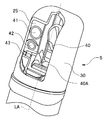
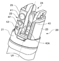
先端部5は、図2A及び図2Bに示すように、先端構成部20と、樹脂等の絶縁性部材により形成されているとともに先端構成部20に対して着脱自在に形成された先端カバー(以下、カバーと略記する)30と、を有して構成されている。図2A及び図2Bは、内視鏡の先端部の構成の一例を説明するための図である。
先端構成部20は、樹脂等の絶縁性部材により形成された先端部本体21と、金属等の硬質部材により形成された光学用凸部22及び起上用凸部23と、を有して構成されている。
光学用凸部22及び起上用凸部23は、先端部本体21から挿入部2の長手軸LA(図2A及び図2B参照)に沿って先端側へ突出して設けられている。また、光学用凸部22と起上用凸部23との間の隙間には、金属等の硬質部材により形成された起上台40を回動自在に収容するための起上台収容空間24が設けられている。また、先端部本体21における起上台40の近傍には、処置具チャンネルチューブ17の内部に挿通された医療用デバイスの先端部を突出させるための処置具突出口40Aが設けられている。また、起上台40の表面には、処置具突出口40Aから突出される医療用デバイスの先端部の突出方向を所定の方向に誘導するための誘導面が形成されている。
光学用凸部22の一面である上面25には、照明光を被写体に照射するための照明レンズ41と、当該照明光の照射に応じて当該被写体から発せられる戻り光を受光するための観察レンズ42と、が設けられている。また、光学用凸部22には、送気送水釦12の操作に応じて内視鏡1に供給される流体を先端構成部20の先端側へ噴出するように形成された洗浄ノズル43が設けられている。すなわち、照明レンズ41及び観察レンズ42の表面に付着した汚れは、洗浄ノズル43から噴出される流体によって除去される。
起上用凸部23には、例えば、起上台操作レバー14の操作に応じて牽引される起上台操作ワイヤ(不図示)と、当該起上台操作ワイヤの牽引状態に応じ、起上台収容空間24に配置された起上台40を回動して起上させることができるように形成された起上台動作機構(不図示)と、が設けられている。
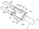
内視鏡用洗浄具51は、細長な挿入機器の先端部を洗浄液により洗浄する際に用いられる挿入機器用洗浄具として構成されている。また、内視鏡用洗浄具51は、図1に示すように、流体注入部52A,52Bと、管路部53A,53Bと、先端部5の先端構成部20に対して着脱自在に構成された洗浄キャップ54と、を有して構成されている。また、洗浄キャップ54は、先端部5の先端構成部20を収容可能な内部空間を形成するキャップ部品54A,54Bを有して構成されている。
流体注入部52Aには、先端部5の先端構成部20を洗浄するための洗浄用の流体(以降、洗浄液とも称する)が注入される開口である注入口62Aが形成されている。また、流体注入部52Aには、注入口62Aから注入された洗浄液が流通する流路を二つに分岐させる分岐部63Aが設けられている。
管路部53Aには、分岐部63Aを経た洗浄液を流通させるための流路を形成する二つのチューブ64A,65Aが設けられている。
チューブ64Aの一端は、分岐部63Aに接続されている。また、チューブ64Aの他端は、キャップ部品54Aに接続されている。すなわち、チューブ64Aは、分岐部63Aを経て流れ込む洗浄液をキャップ部品54Aへ流通させるための流路を有する管路として形成されている。
チューブ65Aの一端は、分岐部63Aに接続されている。また、チューブ65Aの他端は、キャップ部品54Bに接続されている。すなわち、チューブ65Aは、分岐部63Aを経て流れ込む洗浄液をキャップ部品54Bへ流通させるための流路を有する管路として形成されている。
キャップ部品54Aは、チューブ64Aを経て流れ込む洗浄液と、チューブ65Bを経て流れ込む洗浄液と、をそれぞれ異なる開口から排出するように構成されている。
流体注入部52Bには、先端部5の先端構成部20を洗浄するための洗浄液が注入される開口である注入口62Bが形成されている。また、流体注入部52Bには、注入口62Bから注入された洗浄液が流通する流路を二つに分岐させる分岐部63Bが設けられている。
管路部53Bには、分岐部63Bを経た洗浄液を流通させるための流路を形成する二つのチューブ64B,65Bが設けられている。
チューブ64Bの一端は、分岐部63Bに接続されている。また、チューブ64Bの他端は、キャップ部品54Bに接続されている。すなわち、チューブ64Bは、分岐部63Bを経て流れ込む洗浄液をキャップ部品54Bへ流通させるための流路を有する管路として形成されている。
チューブ65Bの一端は、分岐部63Bに接続されている。また、チューブ65Bの他端は、キャップ部品54Aに接続されている。すなわち、チューブ65Bは、分岐部63Bを経て流れ込む洗浄液をキャップ部品54Aへ流通させるための流路を有する管路として形成されている。
キャップ部品54Bは、チューブ65Aを経て流れ込む洗浄液と、チューブ64Bを経て流れ込む洗浄液と、をそれぞれ異なる開口から排出するように構成されている。
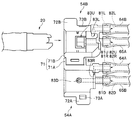
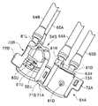
ここで、洗浄キャップ54を形成するキャップ部品54A,54Bの構造の具体例について、図3等を参照しつつ説明する。なお、図3においては、図示の便宜上、先端構成部20の細部に係る構造を省略しているものとする。図3は、実施形態に係る内視鏡用洗浄具のキャップ部品の構成の具体例を説明するための図である。
キャップ部品54Aは、先端構成部20に対して着脱自在であるとともに、後述の排出口83R,83Dを設けて構成されている。また、キャップ部品54Aは、例えば、略半円筒形状を具備し、先端構成部20の下半分(照明レンズ41及び観察レンズ42を含まない部分)を略覆うことができるように構成されている。
キャップ部品54Bは、先端構成部20に対して着脱自在であるとともに、後述の排出口83L,83Uを設けて構成されている。また、キャップ部品54Bは、例えば、略半円筒形状を具備し、先端構成部20の上半分(照明レンズ41及び観察レンズ42を含む部分)を略覆うことができるように構成されている。
キャップ部品54A,54Bは、図3に示すように、ヒンジ機構71により回動自在に連結されている。
ヒンジ機構71は、キャップ部品54Aに形成されたヒンジ接続部71Aと、キャップ部品54Bに形成されたヒンジ接続部71Bと、ヒンジ接続部71A,71Bを回動させる際の回動軸に相当するヒンジ軸(不図示)と、を有して構成されている。
キャップ部品54Aにおけるヒンジ接続部71Aの反対側には、図3に示すように、内視鏡用洗浄具51を使用して洗浄作業を行なう作業者が指で摘むことが可能な形状を有する摘み部72Aが形成されている。また、摘み部72Aの近傍には、係合爪部73Aが形成されている。
キャップ部品54Bにおけるヒンジ接続部71Bの反対側には、図3に示すように、内視鏡用洗浄具51を使用して洗浄作業を行なう作業者が指で摘むことが可能な形状を有する摘み部72Bが形成されている。また、摘み部72Bに隣接する位置には、係合爪部73Aに対して係合可能な形状を有する係合溝部73Bが形成されている。
キャップ部品54A,54Bは、係合爪部73Aと係合溝部73Bとが係合している状態において、先端構成部20を収容可能な内部空間を有するとともに、当該内部空間の所定の位置に先端構成部20を固定しつつ配置することが可能な洗浄キャップ54を形成するように構成されている。すなわち、キャップ部品54A,54Bは、係合爪部73Aと係合溝部73Bとが係合している状態において、先端構成部20を収容可能な内部空間を形成するように構成されている。
キャップ部品54Aには、チューブ64Aの他端を差し込んで接続することができるように形成されたチューブ接続用管路81Rと、チューブ65Bの他端を差し込んで接続することができるように形成されたチューブ接続用管路81Dと、がそれぞれ設けられている。
チューブ接続用管路81Rには、チューブ64Aの他端に到達した洗浄液が流入する開口である流入口82Rと、流入口82Rから流入した洗浄液をチューブ64Aの他端に近接する所定の位置から排出するための開口である排出口83Rと、が形成されている。また、チューブ接続用管路81Rには、排出口83Rから排出される洗浄液の排出方向を、流入口82Rから流入する洗浄液の流通方向に対して直交する方向に設定するための流路が形成されている。そして、このような構成によれば、流入口82Rを経てチューブ接続用管路81Rの内部に流入した洗浄液を、ヒンジ接続部71A側に設けられた排出口83Rから摘み部72A側へ排出することができる。
チューブ接続用管路81Dには、チューブ65Bの他端に到達した洗浄液が流入する開口である流入口82Dと、流入口82Dから流入した洗浄液をチューブ64Aの他端から離れたキャップ部品54Aの内壁の所定の位置から排出するための開口である排出口83Dと、が形成されている。また、チューブ接続用管路81Dには、排出口83Dから排出される洗浄液の排出方向を、流入口82Dから流入する洗浄液の流通方向に対して直交する方向であるとともに、排出口83Rから排出される洗浄液の排出方向に対してねじれの位置になる方向に設定するための流路が形成されている。
キャップ部品54Bには、チューブ64Bの他端を差し込んで接続することができるように形成されたチューブ接続用管路81Lと、チューブ65Aの他端を差し込んで接続することができるように形成されたチューブ接続用管路81Uと、がそれぞれ設けられている。
チューブ接続用管路81Lには、チューブ64Bの他端に到達した洗浄液が流入する開口である流入口82Lと、流入口82Lから流入した洗浄液をチューブ64Bの他端に近接する所定の位置から排出するための開口である排出口83Lと、が形成されている。また、チューブ接続用管路81Lには、排出口83Lから排出される洗浄液の排出方向を、流入口82Lから流入する洗浄液の流通方向に対して直交する方向に設定するための流路が形成されている。そして、このような構成によれば、流入口82Lを経てチューブ接続用管路81Lの内部に流入した洗浄液を、摘み部72B側に設けられた排出口83Lからヒンジ接続部71B側へ排出することができる。
チューブ接続用管路81Uには、チューブ65Aの他端に到達した洗浄液が流入する開口である流入口82Uと、流入口82Uから流入した洗浄液をチューブ64Aの他端から離れたキャップ部品54Bの内壁の所定の位置から排出するための開口である排出口83Uと、が形成されている。また、チューブ接続用管路81Uには、排出口83Uから排出される洗浄液の排出方向を、流入口82Uから流入する洗浄液の流通方向に対して直交する方向であるとともに、排出口83Lから排出される洗浄液の排出方向に対してねじれの位置になる方向に設定するための流路が形成されている。
以上に述べたように、内視鏡用洗浄具51は、注入口62Aと、注入口62Aから注入された流体(洗浄液)が流通する流路をチューブ64A,65Aの各々に連通する二つの流路に分岐させる分岐部63Aと、分岐部63Aを経て当該二つの流路に流通する当該流体を洗浄キャップ54において排出するための排出口83R,83Uと、を備えた流体供給用管路PA(図示省略)を有して構成されている。また、以上に述べたように、内視鏡用洗浄具51は、注入口62Bと、注入口62Bから注入された流体(洗浄液)が流通する流路をチューブ64B,65Bの各々に連通する二つの流路に分岐させる分岐部63Bと、分岐部63Bを経て当該二つの流路に流通する当該流体を洗浄キャップ54において排出するための排出口83L,83Dと、を備えた流体供給用管路PB(図示省略)を有して構成されている。すなわち、内視鏡用洗浄具51の流体供給用管路PAは、流体注入部52Aと、管路部53Aのチューブ64A,65Aと、キャップ部品54Aのチューブ接続用管路81Rと、キャップ部品54Bのチューブ接続用管路81Uと、により構成されている。また、内視鏡用洗浄具51の流体供給用管路PBは、流体注入部52Bと、管路部53Bのチューブ64B,65Bと、キャップ部品54Aのチューブ接続用管路81Dと、キャップ部品54Bのチューブ接続用管路81Lと、により構成されている。
本実施形態の内視鏡用洗浄具51によれば、流体供給用管路PAにおける排出口83Rがキャップ部品54Aに設けられているとともに、流体供給用管路PAにおける排出口83Uがキャップ部品54Bに設けられている。また、本実施形態の内視鏡用洗浄具51によれば、流体供給用管路PBにおける排出口83Lがキャップ部品54Bに設けられているとともに、流体供給用管路PBにおける排出口83Uがキャップ部品54Aに設けられている。すなわち、本実施形態の内視鏡用洗浄具51によれば、一つの流体供給用管路における二つの排出口が、キャップ部品54A,54Bに一つずつ設けられている。
本実施形態の内視鏡用洗浄具51においては、流体供給用管路PAを構成する流体注入部52Aと、流体供給用管路PBを構成する流体注入部52Bと、が同じ形状の部品である共通部品により構成されている。また、本実施形態の内視鏡用洗浄具51においては、流体供給用管路PAを構成する管路部53Aと、流体供給用管路PBを構成する管路部53Bと、が同じ形状の部品である共通部品により構成されている。すなわち、本実施形態の内視鏡用洗浄具51においては、流体供給用管路PA,PBの各々における少なくとも一部が共通部品により構成されている。
続いて、内視鏡用洗浄具51を用いて先端部5(先端構成部20)を洗浄する際に行なわれる洗浄作業の具体例について説明する。
作業者は、使用済の内視鏡1の先端部5に装着されているカバー30を取り外すことにより先端構成部20を露出させた後、例えば、挿入部2を長手軸LAの軸周りに回転することにより、所定の向きに向けた状態の先端構成部20をキャップ部品54A,54Bのうちの一方のキャップ部品(例えばキャップ部品54A)に配置する。
具体的には、作業者は、例えば、光学用凸部22の上面25を排出口83U側に向け、かつ、起上用凸部23の側面を排出口83L側に向けた状態の先端構成部20をキャップ部品54Bに配置する。そして、このような作業者の操作によれば、先端構成部20が、キャップ部品54Bにおいて、例えば、図4に示すような状態で配置される。図4は、実施形態に係る内視鏡用洗浄具の洗浄キャップを内視鏡の先端構成部に装着する途中の状態を示す図である。
作業者は、所定の向きに向けた状態の先端構成部20を前記一方のキャップ部品(例えばキャップ部品54A)に配置した後、係合爪部73Aと係合溝部73Bとを係合させるための操作として、例えば、キャップ部品54A,54Bのうちの他方のキャップ部品(例えばキャップ部品54B)に設けられた摘み部を指で摘んでヒンジ接続部を回動させるような操作を行なう。
具体的には、作業者は、例えば、前述のような向きに向けた状態の先端構成部20をキャップ部品54Bに配置した後、キャップ部品54Aに設けられた摘み部72Aを指で摘んでヒンジ接続部71Aを回動させるような操作を行なうことにより、係合爪部73Aと係合溝部73Bとを係合させる。そして、このような作業者の操作によれば、光学用凸部22の上面25とは反対側の面である下面26(図4参照)が排出口83D側に向けられるとともに、光学用凸部22の側面が排出口83R側に向けられる。
すなわち、以上に述べたような作業者の操作によれば、先端構成部20が、キャップ部品54A,54Bにより形成された洗浄キャップ54の内部空間において、図5A及び図5Bに示すような状態で配置される。なお、図5A及び5Bにおいては、図示の便宜上、先端構成部20の細部に係る構造を省略しているものとする。図5Aは、実施形態に係る内視鏡用洗浄具の洗浄キャップを側方から見た場合の断面図である。図5Bは、実施形態に係る内視鏡用洗浄具の洗浄キャップを上方から見た場合の断面図である。
作業者は、以上に述べたような操作を行なうことにより、洗浄キャップ54を先端構成部20に対して図6に示す状態になるように装着した後、例えば、シリンジ等の器具を用いて注入口62A,62Bから洗浄液を注入するための操作を行なう。図6は、実施形態に係る内視鏡用洗浄具の洗浄キャップを内視鏡の先端部に装着した状態を示す図である。
すなわち、排出口83R,83Uは、洗浄キャップ54(キャップ部品54A,54B)が先端構成部20に対して装着された際に、挿入部2の長手軸LA周りに配置されるとともに、流体(洗浄液)の排出方向が互いにねじれの位置になるような位置関係を有する状態で配置される。また、排出口83L,83Dは、洗浄キャップ54(キャップ部品54A,54B)が先端構成部20に対して装着された際に、挿入部2の長手軸LA周りに配置されるとともに、流体(洗浄液)の排出方向が互いにねじれの位置になるような位置関係を有する状態で配置される。また、排出口83R,83Lは、洗浄キャップ54(キャップ部品54A,54B)が先端構成部20に対して装着された際に、流体(洗浄液)の排出方向が互いに平行になるようなまたは同軸上に位置するような位置関係を有する状態で配置される。また、排出口83U,83Dは、洗浄キャップ54(キャップ部品54A,54B)が先端構成部20に対して装着された際に、流体(洗浄液)の排出方向が互いに平行になるようなまたは同軸上に位置するような位置関係を有する状態で配置される。
注入口62Aから注入された洗浄液は、分岐部63Aを経た後、チューブ64A,65Aの二つの流路に流通するとともに、排出口83R,83Uの二つの開口から同時に排出される。そして、排出口83Rを経た洗浄液は、図7の矢印ERに示すような排出方向に排出されるとともに、光学用凸部22の側面を含む先端構成部20の右面側に付着した汚れを除去する。また、排出口83Uを経た洗浄液は、図7の矢印EUに示すような排出方向に排出されるとともに、起上台40の誘導面を含む先端構成部20の上面側に付着した汚れを除去する。図7は、実施形態に係る内視鏡用洗浄具の洗浄キャップに設けられた排出口を経て排出される流体の排出方向を説明するための図である。
注入口62Bから注入された洗浄液は、分岐部63Bを経た後、チューブ64B,65Bの二つの流路に流通するとともに、排出口83L,83Dの二つの開口から同時に排出される。そして、排出口83Lを経た洗浄液は、図7の矢印ELに示すような排出方向に排出されるとともに、起上用凸部23の側面を含む先端構成部20の左面側に付着した汚れを除去する。また、排出口83Dを経た洗浄液は、図7の矢印EDに示すような排出方向に排出されるとともに、起上台40の誘導面の裏側を含む先端構成部20の下面側に付着した汚れを除去する。
以上に述べたように、本実施形態によれば、排出口83Rを経た洗浄液と、排出口83Uを経た洗浄液と、が、キャップ部品54A,54Bにより形成された洗浄キャップ54の内部空間において、互いにねじれの位置になるような位置関係を有する排出方向にそれぞれ排出される。また、以上に述べたように、本実施形態によれば、洗浄液を注入口62Aから注入した際に、洗浄キャップ54の内部空間に配置された先端構成部20の上面側及び右面側を同時に洗浄することができる。そのため、本実施形態によれば、排出口83Rを経た洗浄液と、排出口83Uを経た洗浄液と、を互いに干渉させずに先端構成部20の所定の二つの位置に対して同時に当てることができ、その結果、先端構成部20を効率的に洗浄することができる。
また、本実施形態によれば、例えば、作業者が、洗浄キャップ54を先端構成部20に対して装着する前に、注入口62Aから水を注入することにより、チューブ64Aを経てキャップ部品54Aの排出口83Rに至る流路と、チューブ65Aを経てキャップ部品54Bの排出口83Uに至る流路と、の二つの流路における詰まり状態を個別に確認することができる。そのため、本実施形態によれば、注入口62Aから注入した洗浄液が流通する二つの流路における詰まりを確実に除去することができ、その結果、先端構成部20を効率的に洗浄することができる。
以上に述べたように、本実施形態によれば、排出口83Lを経た洗浄液と、排出口83Dを経た洗浄液と、が、キャップ部品54A,54Bにより形成された洗浄キャップ54の内部空間において、互いにねじれの位置になるような位置関係を有する排出方向にそれぞれ排出される。また、以上に述べたように、本実施形態によれば、洗浄液を注入口62Bから注入した際に、洗浄キャップ54の内部空間に配置された先端構成部20の下面側及び左面側を同時に洗浄することができる。そのため、本実施形態によれば、排出口83Lを経た洗浄液と、排出口83Dを経た洗浄液と、を互いに干渉させずに先端構成部20の所定の二つの位置に対して同時に当てることができ、その結果、先端構成部20を効率的に洗浄することができる。
また、本実施形態によれば、例えば、作業者が、洗浄キャップ54を先端構成部20に対して装着する前に、注入口62Bから水を注入することにより、チューブ64Bを経てキャップ部品54Bの排出口83Lに至る流路と、チューブ65Bを経てキャップ部品54Aの排出口83Dに至る流路と、の二つの流路における詰まり状態を個別に確認することができる。そのため、本実施形態によれば、注入口62Bから注入した洗浄液が流通する二つの流路における詰まりを確実に除去することができ、その結果、先端構成部20を効率的に洗浄することができる。
ところで、本実施形態においては、例えば、図8に示すように、チューブ接続用管路81Uを通過した洗浄液の排出方向を、内壁部91Uに沿う方向と、内壁部92Uに沿う方向と、の互いに平行な二つの方向に分岐させるための段差を排出口83Uの内壁の一部に設けている。そして、このような構成によれば、例えば、排出口83Uから排出される洗浄液により重点的に洗浄される(先端構成部20の上面側の)領域を拡張することができる。また、前述のような構成によれば、例えば、チューブ接続用管路81Uを通過した洗浄液の排出方向が二つの方向に分岐されているか否かを容易に視認することができるため、排出口83Uの点検に係る作業における負担を軽減することができる。図8は、実施形態に係る内視鏡用洗浄具のキャップ部品の構成を説明するための図である。
なお、本実施形態によれば、例えば、流体供給用管路PAにおいて、分岐部63Aから排出口83Rに至る流路と、分岐部63Aから排出口83Uに至る流路と、が略同等の容積を有するように形成されていてもよい。そして、このような構成によれば、注入口62Aから洗浄液を注入した際に、先端構成部20の上面側に当たる洗浄液の量と、先端構成部20の右面側に当たる洗浄液の量と、を略同じにすることができ、その結果、先端構成部20を更に効率的に洗浄することができる。
また、本実施形態によれば、例えば、流体供給用管路PBにおいて、分岐部63Bから排出口83Lに至る流路と、分岐部63Bから排出口83Dに至る流路と、が略同等の容積を有するように形成されていてもよい。そして、このような構成によれば、注入口62Bから洗浄液を注入した際に、先端構成部20の下面側に当たる洗浄液の量と、先端構成部20の左面側に当たる洗浄液の量と、を略同じにすることができ、その結果、先端構成部20を更に効率的に洗浄することができる。
また、本実施形態によれば、例えば、注入口62A,62Bが、ルアーロック形状を有するシリンジを接続可能な形状に形成されていてもよい。そして、このような構成によれば、例えば、注入口62Aに接続したシリンジと、注入口62Bに接続したシリンジと、をそれぞれ固定した状態で洗浄液を注入することができ、その結果、洗浄液の注入に係る作業における作業効率を向上させることができる。
また、本実施形態によれば、流体注入部52A,52Bが、別体の部品として構成されているものに限らず、一体の部品として構成されていてもよい。そして、このような構成によれば、例えば、注入口62A,62Bを互いに近づけた状態で洗浄液を注入することができ、その結果、洗浄液の注入に係る作業における作業効率を向上させることができる。
また、本実施形態の内視鏡用洗浄具51は、一つの注入口から注入した洗浄液が二つの排出口から排出されるように構成されているものに限らず、例えば、当該一つの注入口から注入した洗浄液が三つ以上の排出口から排出されるように構成されていてもよい。すなわち、本実施形態の内視鏡用洗浄具51の流体供給用管路は、先端構成部20を洗浄するための洗浄用の流体(洗浄液)が注入される注入口と、当該注入口から注入された当該流体が流通する流路を複数の流路に分岐させる分岐部と、当該分岐部を経て当該複数の流路に流通する当該流体を洗浄キャップ54において排出するための複数の排出口と、を有して構成されていればよい。また、本実施形態の内視鏡用洗浄具51は、一つの流体供給用管路を有して構成されていてもよく、または、複数の流体供給用管路を有して構成されていてもよい。
また、本実施形態の内視鏡用洗浄具51の構成を適宜変形することにより、例えば、被検体の内部に挿入可能な細長な挿入機器として構成された処置具等の医療用デバイスの先端部を洗浄することができるようにしてもよい。
また、本実施形態の内視鏡用洗浄具51の構成を適宜変形することにより、キャップ部品54A,54Bが先端構成部20に対して装着された際に、流体供給用管路における二つの排出口から排出される流体(洗浄液)の排出方向が互いに交差するような位置関係を有するようにしてもよい。具体的には、キャップ部品54A,54Bが先端構成部20に対して装着された際に、流体(洗浄液)の排出方向が互いに交差するような位置関係を有する状態で(流体供給用管路PAの)排出口83R,83Uが配置されるようにしてもよい。また、キャップ部品54A,54Bが先端構成部20に対して装着された際に、流体(洗浄液)の排出方向が互いに交差するような位置関係を有する状態で(流体供給用管路PBの)排出口83L,83Dが配置されるようにしてもよい。
本発明は、上述した実施形態に限定されるものではなく、発明の趣旨を逸脱しない範囲内において種々の変更や応用が可能であることは勿論である。
本出願は、2018年1月31日に日本国に出願された特願2018-015055号を優先権主張の基礎として出願するものであり、上記の開示内容は、本願明細書、請求の範囲に引用されるものとする。
Claims (18)
- 細長な挿入機器の先端部を洗浄用の流体により洗浄する際に用いられる挿入機器用洗浄具であって、
前記挿入機器の先端部に対して着脱自在に構成された洗浄キャップと、
前記流体が注入される注入口、前記注入口から注入された前記流体が流通する流路を複数の流路に分岐させる分岐部、及び、前記分岐部を経て前記複数の流路に流通する前記流体を前記洗浄キャップにおいて排出するための複数の排出口を備えた一つのまたは複数の流体供給用管路と、を有し、
前記複数の排出口は、前記洗浄キャップが前記挿入機器の先端部に対して装着された際に、前記流体の排出方向が互いにねじれの位置になるような位置関係を有する状態で配置されることを特徴とする挿入機器用洗浄具。 - 前記洗浄キャップは、前記挿入機器の先端部を収容可能な内部空間を形成する複数のキャップ部品を有して構成される請求項1に記載の挿入機器用洗浄具。
- 前記複数のキャップ部品は互いに着脱可能である請求項2に記載の挿入機器用洗浄具。
- 前記一つの流体供給用管路における前記複数の排出口が、前記複数のキャップ部品の少なくとも一つに一つずつ設けられる請求項2に記載の挿入機器用洗浄具。
- 前記複数の流体供給用管路の各々における少なくとも一部が共通部品により構成される請求項1に記載の挿入機器用洗浄具。
- 前記複数の排出口は、前記洗浄キャップが前記挿入機器の先端部に対して装着された際に、前記挿入機器の長手軸周りに配置される請求項1に記載の挿入機器用洗浄具。
- 前記一つの流体供給用管路における前記分岐部から前記複数の排出口に至る複数の流路が略同等の容積を有している請求項1に記載の挿入機器用洗浄具。
- 細長な挿入機器の先端部を洗浄用の流体により洗浄する際に用いられる挿入機器用洗浄具であって、
前記流体が注入される第1の注入口、前記第1の注入口から注入された前記流体が流通する流路を二つに分岐させる第1の分岐部、並びに、前記第1の分岐部を経た前記流体を排出するための第1の排出口及び第2の排出口を有する第1の流体供給用管路と、
前記流体が注入される第2の注入口、前記第2の注入口から注入された前記流体が流通する流路を二つに分岐させる第2の分岐部、並びに、前記第2の分岐部を経た前記流体を排出するための第3の排出口及び第4の排出口を有する第2の流体供給用管路と、
前記挿入機器の先端部に対して着脱自在であるとともに、前記第1の排出口及び前記第4の排出口を設けて構成された第1のキャップ部品と、
前記挿入機器の先端部に対して着脱自在であるとともに、前記第2の排出口及び前記第3の排出口を設けて構成された第2のキャップ部品と、
を有することを特徴とする挿入機器用洗浄具。 - 前記第1の排出口及び前記第2の排出口は、前記第1のキャップ部品及び前記第2のキャップ部品が前記挿入機器の先端部に対して装着された際に、前記流体の排出方向が互いにねじれの位置になるようなまたは互いに交差するような位置関係を有する状態で配置される請求項8に記載の挿入機器用洗浄具。
- 前記第3の排出口及び前記第4の排出口は、前記第1のキャップ部品及び前記第2のキャップ部品が前記挿入機器の先端部に対して装着された際に、前記流体の排出方向が互いにねじれの位置になるようなまたは互いに交差するような位置関係を有する状態で配置される請求項8に記載の挿入機器用洗浄具。
- 前記第1のキャップ部品及び前記第2のキャップ部品は、前記挿入機器の先端部を収容可能な内部空間を形成するように構成される請求項8に記載の挿入機器用洗浄具。
- 前記第1の排出口及び前記第3の排出口は、前記第1のキャップ部品及び前記第2のキャップ部品が前記挿入機器の先端部に対して装着された際に、前記流体の排出方向が互いに平行になるようなまたは同軸上に位置するような位置関係を有する状態で配置される請求項8に記載の挿入機器用洗浄具。
- 前記第2の排出口及び前記第4の排出口は、前記第1のキャップ部品及び前記第2のキャップ部品が前記挿入機器の先端部に対して装着された際に、前記流体の排出方向が互いに平行になるようなまたは同軸上に位置するような位置関係を有する状態で配置される請求項8に記載の挿入機器用洗浄具。
- 前記第1の流体供給用管路及び前記第2の流体供給用管路の各々における少なくとも一部が共通部品により構成される請求項8に記載の挿入機器用洗浄具。
- 前記第1の流体供給用管路において、前記第1の分岐部から前記第1の排出口に至る流路と、前記第1の分岐部から前記第2の排出口に至る流路と、が略同等の容積を有している請求項8に記載の挿入機器用洗浄具。
- 前記第2の流体供給用管路において、前記第2の分岐部から前記第3の排出口に至る流路と、前記第2の分岐部から前記第4の排出口に至る流路と、が略同等の容積を有している請求項8に記載の挿入機器用洗浄具。
- 前記第1のキャップ部品と第2のキャップ部品は、互いに着脱可能である請求項8に記載の挿入機器用洗浄具。
- 前記第1の排出口乃至第4の排出口は、前記第1のキャップ部品及び前記第2のキャップ部品が前記挿入機器の先端部に対して装着された際に、前記挿入機器の長手軸周りに配置される請求項8に記載の挿入機器用洗浄具。
Priority Applications (3)
| Application Number | Priority Date | Filing Date | Title |
|---|---|---|---|
| CN201880087831.3A CN111655117B (zh) | 2018-01-31 | 2018-07-17 | 插入设备用清洗工具 |
| JP2019568551A JP7105255B2 (ja) | 2018-01-31 | 2018-07-17 | 挿入機器用洗浄具 |
| US16/935,551 US11490799B2 (en) | 2018-01-31 | 2020-07-22 | Cleaning tool for insertion device |
Applications Claiming Priority (2)
| Application Number | Priority Date | Filing Date | Title |
|---|---|---|---|
| JP2018-015055 | 2018-01-31 | ||
| JP2018015055 | 2018-01-31 |
Related Child Applications (1)
| Application Number | Title | Priority Date | Filing Date |
|---|---|---|---|
| US16/935,551 Continuation US11490799B2 (en) | 2018-01-31 | 2020-07-22 | Cleaning tool for insertion device |
Publications (1)
| Publication Number | Publication Date |
|---|---|
| WO2019150600A1 true WO2019150600A1 (ja) | 2019-08-08 |
Family
ID=67478401
Family Applications (1)
| Application Number | Title | Priority Date | Filing Date |
|---|---|---|---|
| PCT/JP2018/026733 Ceased WO2019150600A1 (ja) | 2018-01-31 | 2018-07-17 | 挿入機器用洗浄具 |
Country Status (4)
| Country | Link |
|---|---|
| US (1) | US11490799B2 (ja) |
| JP (1) | JP7105255B2 (ja) |
| CN (1) | CN111655117B (ja) |
| WO (1) | WO2019150600A1 (ja) |
Families Citing this family (1)
| Publication number | Priority date | Publication date | Assignee | Title |
|---|---|---|---|---|
| WO2025224699A1 (en) * | 2024-04-26 | 2025-10-30 | Saban Ventures Pty Limited | Modulated cleaning fluid flow |
Citations (6)
| Publication number | Priority date | Publication date | Assignee | Title |
|---|---|---|---|---|
| JPS565630A (en) * | 1979-06-27 | 1981-01-21 | Olympus Optical Co | Cleaning tool for endoscope |
| JPH03280925A (ja) * | 1990-03-30 | 1991-12-11 | Olympus Optical Co Ltd | 内視鏡洗浄装置 |
| WO2011030679A1 (ja) * | 2009-09-14 | 2011-03-17 | オリンパスメディカルシステムズ株式会社 | 内視鏡洗浄具及び内視鏡洗浄装置 |
| WO2016059920A1 (ja) * | 2014-10-15 | 2016-04-21 | オリンパス株式会社 | 挿入機器の洗浄具 |
| WO2016059921A1 (ja) * | 2014-10-15 | 2016-04-21 | オリンパス株式会社 | 挿入機器の洗浄具 |
| JP6244493B1 (ja) * | 2017-07-03 | 2017-12-06 | 株式会社丸伝 | 係留ロープ用洗浄装置 |
Family Cites Families (2)
| Publication number | Priority date | Publication date | Assignee | Title |
|---|---|---|---|---|
| JPS56100047A (en) | 1980-01-10 | 1981-08-11 | Tokyo Shibaura Electric Co | Ultrasonic dopler apparatus |
| WO2016059919A1 (ja) * | 2014-10-15 | 2016-04-21 | オリンパス株式会社 | 挿入機器の洗浄具 |
-
2018
- 2018-07-17 CN CN201880087831.3A patent/CN111655117B/zh active Active
- 2018-07-17 WO PCT/JP2018/026733 patent/WO2019150600A1/ja not_active Ceased
- 2018-07-17 JP JP2019568551A patent/JP7105255B2/ja active Active
-
2020
- 2020-07-22 US US16/935,551 patent/US11490799B2/en active Active
Patent Citations (6)
| Publication number | Priority date | Publication date | Assignee | Title |
|---|---|---|---|---|
| JPS565630A (en) * | 1979-06-27 | 1981-01-21 | Olympus Optical Co | Cleaning tool for endoscope |
| JPH03280925A (ja) * | 1990-03-30 | 1991-12-11 | Olympus Optical Co Ltd | 内視鏡洗浄装置 |
| WO2011030679A1 (ja) * | 2009-09-14 | 2011-03-17 | オリンパスメディカルシステムズ株式会社 | 内視鏡洗浄具及び内視鏡洗浄装置 |
| WO2016059920A1 (ja) * | 2014-10-15 | 2016-04-21 | オリンパス株式会社 | 挿入機器の洗浄具 |
| WO2016059921A1 (ja) * | 2014-10-15 | 2016-04-21 | オリンパス株式会社 | 挿入機器の洗浄具 |
| JP6244493B1 (ja) * | 2017-07-03 | 2017-12-06 | 株式会社丸伝 | 係留ロープ用洗浄装置 |
Also Published As
| Publication number | Publication date |
|---|---|
| US20200345226A1 (en) | 2020-11-05 |
| JP7105255B2 (ja) | 2022-07-22 |
| JPWO2019150600A1 (ja) | 2020-11-19 |
| US11490799B2 (en) | 2022-11-08 |
| CN111655117A (zh) | 2020-09-11 |
| CN111655117B (zh) | 2023-11-14 |
Similar Documents
| Publication | Publication Date | Title |
|---|---|---|
| US10321806B2 (en) | Endoscope and rigid distal end portion of endoscope | |
| JP5566344B2 (ja) | 内視鏡 | |
| JP5078309B2 (ja) | 内視鏡 | |
| CN106714654B (zh) | 内窥镜 | |
| WO2006073187A1 (ja) | 内視鏡用挿入部 | |
| WO2006109372A1 (ja) | 内視鏡用挿入部 | |
| CN116369831B (zh) | 内窥镜 | |
| WO2006073185A1 (ja) | 内視鏡用挿入部 | |
| CN103549936A (zh) | 内窥镜 | |
| WO2006073188A1 (ja) | 内視鏡用挿入部 | |
| JP5329604B2 (ja) | 内視鏡用流体噴射ノズルユニット及び内視鏡 | |
| JP6203100B2 (ja) | 内視鏡洗浄アタッチメント | |
| JP2014046167A (ja) | 内視鏡 | |
| JP2009279291A (ja) | 内視鏡 | |
| JP6901636B2 (ja) | 内視鏡洗浄具 | |
| JPWO2017183366A1 (ja) | 器具挿入補助具 | |
| WO2019150600A1 (ja) | 挿入機器用洗浄具 | |
| JP2006254999A (ja) | 内視鏡用挿入部及び内視鏡 | |
| JP7073575B2 (ja) | 内視鏡 | |
| JP5390150B2 (ja) | 補助具及び内視鏡システム | |
| JP5990212B2 (ja) | 内視鏡用挿入部及び内視鏡 | |
| JP2012245188A (ja) | 内視鏡 | |
| JP2012183262A (ja) | 内視鏡 | |
| JP2002085328A (ja) | 内視鏡 | |
| JP7097860B2 (ja) | 内視鏡 |
Legal Events
| Date | Code | Title | Description |
|---|---|---|---|
| 121 | Ep: the epo has been informed by wipo that ep was designated in this application |
Ref document number: 18904195 Country of ref document: EP Kind code of ref document: A1 |
|
| ENP | Entry into the national phase |
Ref document number: 2019568551 Country of ref document: JP Kind code of ref document: A |
|
| NENP | Non-entry into the national phase |
Ref country code: DE |
|
| 122 | Ep: pct application non-entry in european phase |
Ref document number: 18904195 Country of ref document: EP Kind code of ref document: A1 |