WO2019150484A1 - 電動機の容量選定装置、容量選定方法および容量選定プログラム - Google Patents
電動機の容量選定装置、容量選定方法および容量選定プログラム Download PDFInfo
- Publication number
- WO2019150484A1 WO2019150484A1 PCT/JP2018/003204 JP2018003204W WO2019150484A1 WO 2019150484 A1 WO2019150484 A1 WO 2019150484A1 JP 2018003204 W JP2018003204 W JP 2018003204W WO 2019150484 A1 WO2019150484 A1 WO 2019150484A1
- Authority
- WO
- WIPO (PCT)
- Prior art keywords
- pattern
- axis system
- system model
- capacity
- inertia
- Prior art date
- Legal status (The legal status is an assumption and is not a legal conclusion. Google has not performed a legal analysis and makes no representation as to the accuracy of the status listed.)
- Ceased
Links
Images






Classifications
-
- H—ELECTRICITY
- H02—GENERATION; CONVERSION OR DISTRIBUTION OF ELECTRIC POWER
- H02P—CONTROL OR REGULATION OF ELECTRIC MOTORS, ELECTRIC GENERATORS OR DYNAMO-ELECTRIC CONVERTERS; CONTROLLING TRANSFORMERS, REACTORS OR CHOKE COILS
- H02P6/00—Arrangements for controlling synchronous motors or other dynamo-electric motors using electronic commutation dependent on the rotor position; Electronic commutators therefor
- H02P6/34—Modelling or simulation for control purposes
-
- H—ELECTRICITY
- H02—GENERATION; CONVERSION OR DISTRIBUTION OF ELECTRIC POWER
- H02P—CONTROL OR REGULATION OF ELECTRIC MOTORS, ELECTRIC GENERATORS OR DYNAMO-ELECTRIC CONVERTERS; CONTROLLING TRANSFORMERS, REACTORS OR CHOKE COILS
- H02P5/00—Arrangements specially adapted for regulating or controlling the speed or torque of two or more electric motors
- H02P5/46—Arrangements specially adapted for regulating or controlling the speed or torque of two or more electric motors for speed regulation of two or more dynamo-electric motors in relation to one another
-
- G—PHYSICS
- G05—CONTROLLING; REGULATING
- G05B—CONTROL OR REGULATING SYSTEMS IN GENERAL; FUNCTIONAL ELEMENTS OF SUCH SYSTEMS; MONITORING OR TESTING ARRANGEMENTS FOR SUCH SYSTEMS OR ELEMENTS
- G05B19/00—Program-control systems
- G05B19/02—Program-control systems electric
- G05B19/18—Numerical control [NC], i.e. automatically operating machines, in particular machine tools, e.g. in a manufacturing environment, so as to execute positioning, movement or co-ordinated operations by means of program data in numerical form
- G05B19/402—Numerical control [NC], i.e. automatically operating machines, in particular machine tools, e.g. in a manufacturing environment, so as to execute positioning, movement or co-ordinated operations by means of program data in numerical form characterised by control arrangements for positioning, e.g. centring a tool relative to a hole in the workpiece, additional detection means to correct position
-
- G—PHYSICS
- G05—CONTROLLING; REGULATING
- G05B—CONTROL OR REGULATING SYSTEMS IN GENERAL; FUNCTIONAL ELEMENTS OF SUCH SYSTEMS; MONITORING OR TESTING ARRANGEMENTS FOR SUCH SYSTEMS OR ELEMENTS
- G05B19/00—Program-control systems
- G05B19/02—Program-control systems electric
- G05B19/18—Numerical control [NC], i.e. automatically operating machines, in particular machine tools, e.g. in a manufacturing environment, so as to execute positioning, movement or co-ordinated operations by means of program data in numerical form
- G05B19/414—Structure of the control system, e.g. common controller or multiprocessor systems, interface to servo, programmable interface controller
-
- H—ELECTRICITY
- H02—GENERATION; CONVERSION OR DISTRIBUTION OF ELECTRIC POWER
- H02P—CONTROL OR REGULATION OF ELECTRIC MOTORS, ELECTRIC GENERATORS OR DYNAMO-ELECTRIC CONVERTERS; CONTROLLING TRANSFORMERS, REACTORS OR CHOKE COILS
- H02P23/00—Arrangements or methods for the control of AC motors characterised by a control method other than vector control
- H02P23/0077—Characterised by the use of a particular software algorithm
-
- H—ELECTRICITY
- H02—GENERATION; CONVERSION OR DISTRIBUTION OF ELECTRIC POWER
- H02P—CONTROL OR REGULATION OF ELECTRIC MOTORS, ELECTRIC GENERATORS OR DYNAMO-ELECTRIC CONVERTERS; CONTROLLING TRANSFORMERS, REACTORS OR CHOKE COILS
- H02P29/00—Arrangements for regulating or controlling electric motors, appropriate for both AC and DC motors
-
- H—ELECTRICITY
- H02—GENERATION; CONVERSION OR DISTRIBUTION OF ELECTRIC POWER
- H02P—CONTROL OR REGULATION OF ELECTRIC MOTORS, ELECTRIC GENERATORS OR DYNAMO-ELECTRIC CONVERTERS; CONTROLLING TRANSFORMERS, REACTORS OR CHOKE COILS
- H02P6/00—Arrangements for controlling synchronous motors or other dynamo-electric motors using electronic commutation dependent on the rotor position; Electronic commutators therefor
- H02P6/04—Arrangements for controlling or regulating the speed or torque of more than one motor
-
- G—PHYSICS
- G05—CONTROLLING; REGULATING
- G05B—CONTROL OR REGULATING SYSTEMS IN GENERAL; FUNCTIONAL ELEMENTS OF SUCH SYSTEMS; MONITORING OR TESTING ARRANGEMENTS FOR SUCH SYSTEMS OR ELEMENTS
- G05B2219/00—Program-control systems
- G05B2219/30—Nc systems
- G05B2219/43—Speed, acceleration, deceleration control ADC
- G05B2219/43036—Velocity profile with given starting and stopping speed vector
-
- G—PHYSICS
- G05—CONTROLLING; REGULATING
- G05B—CONTROL OR REGULATING SYSTEMS IN GENERAL; FUNCTIONAL ELEMENTS OF SUCH SYSTEMS; MONITORING OR TESTING ARRANGEMENTS FOR SUCH SYSTEMS OR ELEMENTS
- G05B2219/00—Program-control systems
- G05B2219/30—Nc systems
- G05B2219/50—Machine tool, machine tool null till machine tool work handling
Definitions
- the present invention relates to a motor capacity selection device, a capacity selection method, and a capacity selection program in a multi-axis system having a plurality of motors.
- Patent Document 1 describes an invention for selecting the capacity of each of a plurality of electric motors constituting a multi-axis system.
- the motor capacity selection device described in Patent Document 1 performs simulation using information such as selection of element models, connection information between element models, physical parameters for each element model, and the like, and selects the capacity of each motor.
- the capacity selection device for an electric motor described in Patent Document 1 has a high degree of freedom in a multi-axis system to be constructed, it is necessary for a user to construct a multi-axis system by performing an operation of connecting machine elements. Therefore, before starting to use the capacity selection device for the motor, the user needs to acquire knowledge necessary for connecting the machine elements, and when using the capacity selection device for the motor. Requires work to connect machine elements. As described above, the invention described in Patent Document 1 has a problem that the load on the user is large.
- the present invention has been made in view of the above, and an object of the present invention is to obtain an electric motor capacity selection device capable of reducing the load on the user.
- a capacity selection device for an electric motor includes a plurality of types of multi-axis systems that represent a configuration of a multi-axis system configured by combining a plurality of machine elements and a plurality of motors.
- a multi-axis system model holding unit for holding the axis system model is provided.
- the capacity selection device for the motor also selects a multi-axis system model based on a selected multi-axis system model that is one multi-axis system model selected from a plurality of types of multi-axis system models held by the multi-axis system model holding unit.
- a capacity selection unit is provided for selecting the capacity of each of the plurality of electric motors constituting the multi-axis system model represented by the axis system model.
- the capacity selection device for an electric motor further includes a selection result notifying unit for notifying a selection result by the capacity selecting unit.
- the motor capacity selection device has an effect of reducing the load on the user.
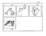
- capacitance selection apparatus of the electric motor concerning embodiment The figure which shows an example of the multi-axis system model holding
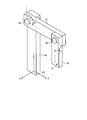
- capacitance selection apparatus of the electric motor concerning embodiment Schematic diagram of mechanism of biaxial manipulator held in multi-axis system model holding section according to embodiment
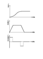
- capacitance selection apparatus of the electric motor concerning embodiment The figure which shows an example of the operation pattern of the machine end which the operation pattern acquisition part concerning embodiment acquires
- the figure which shows an example of the inertia pattern of the machine end which the inertia pattern acquisition part concerning embodiment acquires
- FIG. 1 is a diagram illustrating a configuration example of a capacity selection device for an electric motor according to an embodiment of the present invention.
- the motor capacity selection device 1 shown in FIG. 1 selects the capacity of an electric motor that drives each of a plurality of drive shafts included in a multi-axis system.
- the multi-axis system is configured by combining a plurality of machine elements and a plurality of electric motors.
- the multi-axis system has a configuration in which a plurality of mechanical elements are connected to each other via a drive shaft, and each drive shaft is rotationally driven by an electric motor.
- the motor whose capacity is selected by the motor capacity selection device 1 is assumed to be constituted by a motor and a drive circuit that drives the motor. That is, the motor capacity selection device 1 selects the capacity of the motor and the drive circuit of the motor.
- the drive circuit includes circuits such as an inverter and a servo amplifier.
- the capacity selection device 1 for an electric motor includes a multi-axis system model holding unit 10, a specification information acquisition unit 11, an operation pattern acquisition unit 12, a load pattern acquisition unit 13, an inertia pattern acquisition unit 14, 1 calculation unit 15, calculation result holding unit 16, calculation result selection unit 17, capacity selection processing unit 18, selection result notification unit 19, and second calculation unit 20.
- the first calculation unit 15, the calculation result holding unit 16, the calculation result selection unit 17, the capacity selection processing unit 18, and the second calculation unit 20 constitute a capacity selection unit 2.
- the capacity selection device for an electric motor may be referred to as “capacity selection device”.
- the multi-axis system model holding unit 10 holds a multi-axis system model representing the configuration of the multi-axis system.
- the multi-axis system model includes information such as the type and number of machine elements constituting the multi-axis system, the connection relation between the machine elements, and the correspondence relation between the machine elements and the electric motor.
- the multi-axis system model holding unit 10 holds a multi-axis system model for each of a plurality of types of multi-axis systems having different configurations.
- the multi-axis system model is created in advance by an external computer or the like and written in the multi-axis system model holding unit 10.
- the multi-axis system model holding unit 10 outputs one of the multi-axis system models held when the first calculation unit 15 performs the calculation described later to the first calculation unit 15, and the second calculation unit When the computer 20 executes a calculation to be described later, one of the stored multi-axis system models is output to the second calculator 20.
- the specification information acquisition unit 11 acquires the specification information of the multi-axis system model from the outside. That is, the specification information acquisition unit 11 receives input of specification information of the multi-axis system model by the user.
- An example of the specification information of the multi-axis system model is the size and mass of each machine element constituting the multi-axis system.
- the specification information acquisition unit 11 retains the specification information when it is acquired from the outside, and outputs the specification information to the first calculation unit 15 when the first calculation unit 15 executes a calculation to be described later. When the second calculation unit 20 executes a calculation described later, the specification information is output to the second calculation unit 20.
- the operation pattern acquisition unit 12 acquires an operation pattern at the machine end of the multi-axis system, which is a part where the multi-axis system holds a work and performs work from the outside. That is, the operation pattern acquisition unit 12 receives an input of an operation pattern at the machine end of the multi-axis system by the user.
- the position of the machine end of the multi-axis system changes when each electric motor constituting the multi-axis system drives each drive shaft.
- the multi-axis system is a machine tool for machining a workpiece, a tool or a workpiece is attached to the machine end.
- the operation pattern is information representing a time change in the position of the machine end of the multi-axis system.
- the driving pattern acquisition unit 12 When the driving pattern acquisition unit 12 acquires the driving pattern, the driving pattern acquisition unit 12 outputs the driving pattern to the first calculation unit 15.
- the driving pattern acquisition unit 12 accepts an operation for changing the driving pattern held in the calculation result holding unit 16 described later from the outside, and is held in the calculation result holding unit 16 according to the received operation content. Change the driving pattern.
- the load pattern acquisition unit 13 acquires a load pattern at the machine end of the multi-axis system from the outside. That is, the load pattern acquisition unit 13 receives an input of a load pattern at the machine end of the multi-axis system by the user.
- the load pattern is information representing a time change of a load applied to the machine end of the multi-axis system.
- the load pattern acquisition unit 13 outputs the load pattern to the first calculation unit 15.
- the inertia pattern acquisition unit 14 acquires an inertia pattern at the machine end of the multi-axis system from the outside. That is, the inertia pattern acquisition unit 14 receives an input of an inertia pattern at the machine end of the multi-axis system by the user.
- the inertia pattern is information representing the time change of the inertia applied to the machine end of the multi-axis system.
- the inertia pattern acquisition unit 14 outputs the inertia pattern to the first calculation unit 15.
- the first calculation unit 15 calculates an operation pattern, a load pattern, and an inertia pattern of each of the plurality of electric motors constituting the multi-axis system.
- the calculation result holding unit 16 holds the calculation result by the first calculation unit 15, that is, the operation pattern, load pattern, and inertia pattern of each of the plurality of electric motors calculated by the first calculation unit 15.
- the calculation result selection unit 17 selects a part of the calculation results held by the calculation result holding unit 16 and inputs the selected calculation results to the capacity selection processing unit 18.
- the capacity selection processing unit 18 selects the capacity of the electric motor based on the calculation result input from the calculation result selection unit 17.
- the selection result notification unit 19 notifies the selection result by the capacity selection processing unit 18.
- the second calculation unit 20 calculates the operation pattern, load pattern, and inertia pattern at the machine end of the multi-axis system.
- FIG. 2 is a diagram illustrating an example of the multi-axis system model holding unit 10 included in the motor capacity selection device 1 according to the embodiment.
- the multi-axis system model holding unit 10 holds a multi-axis system model of a plurality of types of multi-axis systems.
- the multi-axis system model holding unit 10 includes a multi-axis system model 51 representing a vertical articulated robot, a multi-axis system model 52 representing a horizontal articulated robot, and a multi-axis system model representing a parallel link robot. 53, a multi-axis system model 54 representing a gantry robot, and the like.
- the multi-axis system model held by the multi-axis system model holding unit 10 is not limited to the one shown in FIG.
- FIG. 3 is a diagram illustrating an example of hardware that realizes the motor capacity selection device 1 according to the embodiment.
- the capacity selection device 1 can be realized by the computer 100 including the arithmetic device 101, the storage device 102, the input device 103, and the display device 104 shown in FIG.
- a CPU Central Processing Unit
- a RAM Random Access Memory
- a ROM Read Only Memory
- a mouse, a keyboard, a touch panel, or the like can be applied to the input device 103
- a liquid crystal monitor, a display, or the like can be applied to the display device 104.
- the first calculation unit 15, the calculation result selection unit 17, the capacity selection processing unit 18, and the second calculation unit 20 of the capacity selection device 1 are realized by the arithmetic device 101 executing programs for operating as these units.
- the Programs for operating as the first calculation unit 15, the capacity selection processing unit 18, and the second calculation unit 20 are stored in the storage device 102 in advance.
- the arithmetic device 101 operates as the first calculation unit 15, the capacity selection processing unit 18, and the second calculation unit 20 by reading the program from the storage device 102 and executing it.
- the multi-axis system model holding unit 10 and the calculation result holding unit 16 of the capacity selection device 1 are realized by the storage device 102.
- the specification information acquisition unit 11, the operation pattern acquisition unit 12, the load pattern acquisition unit 13, and the inertia pattern acquisition unit 14 of the capacity selection device 1 are realized by the input device 103.
- the selection result notification unit 19 is realized by the display device 104.
- the capacity selection device 1 selects the capacity of the motor by taking as an example the case where the multi-axis system is a 2-axis manipulator.
- FIG. 4 is a schematic diagram of the mechanism of the biaxial manipulator held in the multi-axis system model holding unit 10 of the capacity selection device 1 according to the embodiment.
- the two-axis manipulator that is the multi-axis system shown in FIG. 4 includes a first link 30, a second link 31, and a third link 32.
- One end of the first link 30 is fixed, and the position does not change due to an external force.
- One end of the second link 31 is connected to the other end of the first link 30 via a first reduction gear and a first coupling (not shown).
- the second link 31 is rotationally driven by the first electric motor 35 fixed to the other end of the first link 30 via the first speed reducer and the first coupling.
- One end of the third link 32 is connected to the other end of the second link 31 via a second reduction gear and a second coupling that are not shown.
- the third link 32 is rotationally driven by the second electric motor 36 fixed to the other end of the second link 31 via the second reduction gear and the second coupling.
- the other end of the third link 32 includes a mechanical end 41 of a biaxial manipulator.
- the machine end 41 is the center point of the end face of the third link 32.
- the position of the machine end 41 is represented by the illustrated coordinate system 40.
- the coordinate system 40 is a coordinate system fixed to one end of the first link 30.
- the angle ⁇ 1 is the rotation angle of the first electric motor 35, and the angle ⁇ 2 is the rotation angle of the second electric motor 36.
- the machine end 41 moves to a desired position in a space defined based on the multi-axis system model by operating at least one of the first electric motor 35 and the second electric motor 36.
- the 1st link 30, the 2nd link 31, the 3rd link 32, the 1st reduction gear, the 1st coupling, the 2nd reduction gear, and the 2nd coupling are machine elements which constitute a 2 axi
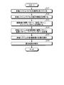
- FIG. 5 is a flowchart illustrating an example of the operation of the capacity selection device 1 according to the embodiment.
- the flowchart shown in FIG. 5 shows an operation in which the capacity selection device 1 selects the capacity of each motor of the multi-axis system.
- the operation according to the flowchart shown in FIG. 5 is started when an operation for instructing the start of the motor capacity selection operation is received from the user.
- a menu for causing the user to select one of a plurality of multi-axis system models held by the multi-axis system model holding unit 10 is displayed on the display device 104.
- Display and accept selection of a multi-axis system model step S11.
- the biaxial manipulator having the configuration shown in FIG. 4 is selected.
- the first motor 35 is the first capacity selection target motor
- the second motor 36 is the second capacity selection target motor.
- the specification information acquisition unit 11 is notified of the selection result of the multi-axis system model.
- the capacity selection device 1 acquires the specification information of the selected multi-axis system model (step S12). Specifically, the capacity selection device 1 displays a menu for allowing the user to input the specification information of the selected multi-axis system on the display device 104, and acquires the specification information by receiving the input.
- the specification information acquisition unit 11 acquires specification information related to the multi-axis system model selected in step S11. Examples of the specification information acquired by the specification information acquisition unit 11 are the dimensions, mass, moment of inertia, reduction ratio, friction coefficient, and the like of each machine element constituting the multi-axis system model.
- Specific examples of the specification information acquired by the specification information acquisition unit 11 include the length of the first link 30, the length and mass of the second link 31, the length and mass of the third link 32, and the first reduction gear.
- the connection part of the 1st link 30 and the 2nd link 31 contains a 1st reduction gear and a 1st coupling.
- the connection part of the 2nd link 31 and the 3rd link 32 contains a 2nd reduction gear and a 2nd coupling.
- the specification information acquisition unit 11 does not input the specification information common to the selection work of both the first capacity selection target motor and the second capacity selection target motor, and inputs the specification information by a single input. get.
- the mass of the third link 32 is necessary for the selection work of both the first capacity selection target motor and the second capacity selection target motor, when information is input to one capacity selection target motor, the other It is treated that information is input to the capacity selection target motor. With such a configuration, it is possible to reduce the user's workload and shorten the work time. It is also possible to prevent mistakes such as erroneous input of different information where the same information should be input.
- the capacity selection device 1 acquires the operation pattern, load pattern, and inertia pattern of the machine end 41 of the selected multi-axis system model (step S13). Specifically, the capacity selection device 1 displays a menu for allowing the user to input the operation pattern, load pattern, and inertia pattern of the machine end 41 on the display device 104, and receives the input to operate the machine end 41. Get pattern, load pattern and inertia pattern.
- the operation pattern acquisition unit 12 acquires the operation pattern of the machine end 41
- the load pattern acquisition unit 13 acquires the load pattern of the machine end 41
- the inertia pattern acquisition unit 14 acquires the inertia pattern of the machine end 41. To get.
- the example of the operation pattern of the machine end 41 acquired by the operation pattern acquisition unit 12 is the position, speed, acceleration, angle, angular velocity, angular acceleration of the machine end 41 or a combination thereof.
- FIG. 6 is a diagram illustrating an example of an operation pattern of the machine end 41 acquired by the operation pattern acquisition unit 12.
- v x is the X direction of the velocity in the coordinate system 40 shown in FIG.
- v y is the velocity in the Y direction in the coordinate system 40.
- v z is the velocity in the Z direction in the coordinate system 40.
- FIG. 7 is a diagram illustrating an example of a load pattern of the machine end 41 acquired by the load pattern acquisition unit 13.
- F x is a force applied in the X direction in the coordinate system 40 shown in FIG.
- F y is a force applied in the Y direction in the coordinate system 40.
- F z is a force applied in the Z direction in the coordinate system 40.
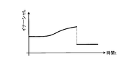
- FIG. 8 is a diagram illustrating an example of the inertia pattern of the machine end 41 acquired by the inertia pattern acquisition unit 14.
- Me is the mass at the machine end 41.
- the capacity selection device 1 calculates an operation pattern, a load pattern, and an inertia pattern of each motor constituting the multi-axis system based on the information acquired in steps S11 to S13 (step S14).
- the first calculation unit 15 calculates the operation pattern, the load pattern, and the inertia pattern.
- the first calculation unit 15 includes the multi-axis system model, the specification information of the multi-axis system model, the operation pattern of the machine end of the multi-axis system, the load pattern of the machine end of the multi-axis system, and the multi-axis system.
- the capacity selection device 1 calculates an operation pattern, a load pattern, and an inertia pattern for the first motor 35 that is a first capacity selection target motor and the second motor 36 that is a second capacity selection target motor.
- An example of the driving pattern calculated by the first calculator 15 is a combination of position, velocity, and acceleration, or a combination of angle, angular velocity, and angular acceleration.
- FIG. 9 is a diagram illustrating an example of an operation pattern calculated by the first calculation unit 15. 9, ⁇ 1 is the angle of the first electric motor 35, ⁇ ′ 1 is the angular velocity of the first electric motor 35, and ⁇ ′′ 1 is the angular acceleration of the first electric motor 35.
- the first calculation unit 15 is the second electric motor 36.
- the angle, angular velocity, and angular acceleration are also calculated.
- FIG. 10 is a diagram illustrating an example of a load pattern calculated by the first calculation unit 15.
- T 1 is the torque of the first electric motor 35.
- the first calculator 15 also calculates the load pattern of the second electric motor 36.
- FIG. 11 is a diagram illustrating an example of an inertia pattern calculated by the first calculation unit 15.
- I 1 is the moment of inertia of the first electric motor 35.
- the first calculator 15 also calculates the inertia pattern of the second electric motor 36.
- the operation pattern, load pattern, and inertia pattern of the first motor 35 and the second motor 36 calculated by the first calculator 15 are held in the calculation result holding unit 16.
- the capacity selection device 1 determines the capacity of each motor constituting the multi-axis system based on the operation pattern, load pattern, and inertia pattern of each motor (first motor 35, second motor 36) calculated in step S14. Is selected (step S15).
- the capacity selection processing unit 18 selects the capacity of each motor.
- the calculation result selection unit 17 selects a necessary calculation result from the calculation results held in the calculation result holding unit 16 and inputs the selected calculation result to the capacity selection processing unit 18. That is, when the capacity selection processing unit 18 selects the capacity of the first electric motor 35, the calculation result selection unit 17 reads the operation pattern, load pattern, and inertia pattern of the first electric motor 35 from the calculation result holding unit 16 and sets the capacity.
- the calculation result selection unit 17 reads out the operation pattern, load pattern, and inertia pattern of the second electric motor 36 from the calculation result holding unit 16 and performs capacity selection processing. Input to the unit 18.
- the capacity selection processing unit 18 sets the first capacity of the motor that can operate in accordance with the input operation pattern, load pattern, and inertia pattern. The capacity of the electric motor 35 is selected.
- the capacity selection processing unit 18 has a capacity of the motor that can operate in accordance with the input operation pattern, load pattern, and inertia pattern. Is selected as the capacity of the second electric motor 36.
- the capacity selection processing unit 18 determines the capacity of the motor that can be operated according to the motor movement pattern if at least the operation pattern of the motor (operation pattern of the first motor 35, operation pattern of the second motor 36) is known. It is possible to select. Therefore, the calculation result selection unit 17 may input at least the operation pattern of the electric motor to the capacity selection processing unit 18.
- the capacity selection processing unit 18 selects the capacity of the motor based on the input motion pattern when only the motor operation pattern is input, and at least one of the load pattern and the inertia pattern in addition to the motor motion pattern. Is input, the capacity of the motor is selected based on the input information.
- the capacity selection device 1 notifies the selection result in step S15 (step S16).
- the selection result notifying unit 19 notifies the user of the capacity of the first motor 35 and the capacity of the second motor 36 selected by the capacity selection processing unit 18 by displaying them on the display device.
- the selection result notification unit 19 may generate data indicating the selection result and output the data to the outside instead of displaying the selection result by the capacity selection processing unit 18 or in addition to the display of the selection result. Good. Further, the selection result notification unit 18 may notify the selection result by voice instead of or in addition to the display.
- the capacity selection device 1 may display the operation patterns of the first electric motor 35 and the second electric motor 36 in addition to the above selection result.
- the capacity selection device 1 may accept a change in the operation pattern of the first electric motor 35 and the second electric motor 36. That is, the capacity selection device 1 displays the selection result in step S15, the operation pattern of the first motor 35 and the operation pattern of the second motor 36 held by the calculation result holding unit 16, and the operation pattern is displayed by the user. It is also possible to wait for the change operation to be performed.
- the capacity selection device 1 performs the first electric motor 35 and the second electric motor based on the changed operation pattern. The capacity of 36 is selected again.
- the driving pattern acquisition unit 12 receives the change of the driving pattern. In other words, when the operation pattern acquisition unit 12 receives the operation pattern change operation, the operation pattern of the first electric motor 35 and the operation pattern of the second electric motor 36 held by the calculation result holding unit 16 according to the received change operation. Change at least one. When the operation pattern held is changed, the calculation result holding unit 16 outputs the changed operation pattern to the second calculation unit 20.
- FIG. 12 is a flowchart showing an example of an operation in which the capacity selection device 1 performs the selection of the electric motor (the first electric motor 35 and the second electric motor 36) again.
- the flowchart shown in FIG. 12 shows an operation when accepting a change in the operation pattern of the electric motor. Steps S21 to S23 shown in FIG. 12 are executed following step S16 shown in FIG.
- the capacity selection device 1 When the capacity selection device 1 receives an operation for changing at least one of the operation pattern of the first motor 35 and the operation pattern of the second motor 36 and the operation pattern is changed (step S21), the capacity selection device 1 executes steps S22 to S25. Reselect the capacity of each motor in the multi-axis system and re-notify the selection result.
- the second calculation unit 20 of the capacity selection device 1 performs forward kinematics calculation using the operation pattern of the first electric motor 35 and the operation pattern of the second electric motor 36 after the change, and the machine end 41 ,
- the load pattern of the machine end 41 and the inertia pattern of the machine end 41 are calculated (step S22).
- the first calculation unit 15 acquires the operation pattern of the machine end 41, the load pattern of the machine end 41, and the inertia pattern of the machine end 41 calculated by the second calculation unit 20 in step S12 illustrated in FIG.
- Inverse kinematics calculation is performed using the already-completed specification information, and the operation pattern, load pattern, and inertia pattern of each motor (first motor 35, second motor 36) of the multi-axis system are calculated again (step S23).
- the process of step S23 is the same process as step S14 shown in FIG.
- step S24 the capacity selection processing unit 18 selects the capacity of each motor again based on the operation pattern, load pattern, and inertia pattern of each motor calculated by the first calculation unit 15 (step S24).
- the process of step S24 is the same process as step S15 shown in FIG.
- the capacity selection device 1 re-selects the capacity of each motor of the multi-axis system, that is, the first motor 35 and the second motor 36, and then re-notifies the selection result (step S25).
- the capacity selection device 1 performs the operation pattern and load pattern of the machine end 41 of the multi-axis system based on the changed operation pattern.
- the inertia pattern is calculated, and further, the motor constituting the multi-axis system is selected again based on the operation pattern, load pattern, and inertia pattern of the machine end 41 of the multi-axis system.
- the capacity selection apparatus 1 for an electric motor has a multi-axis system model that represents a configuration of a multi-axis system configured by combining a plurality of machine elements and a plurality of electric motors.
- the selected multi-axis system model is configured based on the multi-axis system model selected from the multi-axis system model held by the multi-axis system model holding unit 10 and the multi-axis system model holding unit 10
- the capacity selection unit 2 that selects the capacity of each motor and the selection result notification unit 19 that notifies the capacity selection result of each motor by the capacity selection unit 2 are provided.
- the user does not need to connect the machine elements, and the load on the user can be reduced.
- the first calculator 15 uses the inverse kinematics using the machine end operation pattern of the multi-axis system, the load pattern of the machine end of the multi-axis system, and the inertia pattern of the machine end of the multi-axis system. It was decided to obtain the operation pattern, load pattern, and inertia pattern of each motor constituting the multi-axis system by performing the calculation.
- the first calculation unit 15 determines the multi-axis system model and the multi-axis system model specification information and at least one of the operation pattern, load pattern, and inertia pattern at the machine end of the multi-axis system. You may make it calculate the driving
- the second calculation unit 20 does not calculate all the operation patterns, load patterns, and inertia patterns of the machine end of the multi-axis system, but only the information used by the first calculation unit 15 in the inverse kinematic calculation. What is necessary is just to calculate. For example, when the first calculation unit 15 is configured to perform reverse kinematic calculation using only the machine end operation pattern, the second calculation unit 20 may calculate only the machine end operation pattern.
- the configuration described in the above embodiment shows an example of the contents of the present invention, and can be combined with another known technique, and can be combined with other configurations without departing from the gist of the present invention. It is also possible to omit or change the part.
- 1 motor capacity selection device 1 motor capacity selection device, 2 capacity selection unit, 10 multi-axis system model holding unit, 11 specification information acquisition unit, 12 operation pattern acquisition unit, 13 load pattern acquisition unit, 14 inertia pattern acquisition unit, 15 first calculation unit , 16 calculation result holding unit, 17 calculation result selection unit, 18 capacity selection processing unit, 19 selection result notification unit, 20 second calculation unit, 30 first link, 31 second link, 32 third link, 35 first motor 36, 2nd motor, 40 coordinate system, 41 machine end, 51-54 multi-axis system model.
Landscapes
- Engineering & Computer Science (AREA)
- Power Engineering (AREA)
- Human Computer Interaction (AREA)
- Manufacturing & Machinery (AREA)
- Physics & Mathematics (AREA)
- General Physics & Mathematics (AREA)
- Automation & Control Theory (AREA)
- Control Of Multiple Motors (AREA)
- Control Of Electric Motors In General (AREA)
Abstract
Description
図1は、本発明の実施の形態にかかる電動機の容量選定装置の構成例を示す図である。図1に示した電動機の容量選定装置1は、多軸システムが備える複数の駆動軸のそれぞれを駆動させる電動機の容量を選定する。多軸システムは、複数の機械要素および複数の電動機を組み合わせて構成される。具体的には、多軸システムは、複数の機械要素同士が駆動軸を介して連結され、各駆動軸が電動機により回転駆動される構成となっている。なお、電動機の容量選定装置1によって容量が選定される電動機は、モータおよびモータを駆動する駆動回路によって構成されているものとする。すなわち、電動機の容量選定装置1は、モータおよびモータの駆動回路の容量を選定する。駆動回路は、インバータおよびサーボアンプといった回路を含む。
Claims (17)
- 複数の機械要素および複数の電動機を組み合わせて構成される多軸システムの構成を表す複数種類の多軸システムモデルを保持する多軸システムモデル保持部と、
前記多軸システムモデル保持部が保持する前記複数種類の多軸システムモデルの中から選択された一つの多軸システムモデルである選択多軸システムモデルに基づいて、前記選択多軸システムモデルが表す多軸システムモデルを構成する複数の電動機それぞれの容量を選定する容量選定部と、
前記容量選定部による選定結果を報知する選定結果報知部と、
を備えることを特徴とする電動機の容量選定装置。 - 前記選択多軸システムモデルが表す多軸システムの各機械要素の諸元情報を取得する諸元情報取得部と、
前記選択多軸システムモデルが表す多軸システムの機械端の運転パターンである第1の運転パターンを取得する運転パターン取得部と、
を備え、
前記容量選定部は、前記諸元情報と、前記第1の運転パターンと、前記選択多軸システムモデルとに基づいて前記容量を選定する、
ことを特徴とする請求項1に記載の電動機の容量選定装置。 - 前記選択多軸システムモデルが表す多軸システムの機械端の負荷パターンである第1の負荷パターンを取得する負荷パターン取得部と、
前記選択多軸システムモデルが表す多軸システムの機械端のイナーシャパターンである第1のイナーシャパターンを取得するイナーシャパターン取得部と、
を備え、
前記容量選定部は、前記諸元情報、前記第1の運転パターンおよび前記選択多軸システムモデルと、前記第1の負荷パターンおよび前記第1のイナーシャパターンの少なくともいずれか一方とに基づいて、前記容量を選定する、
ことを特徴とする請求項2に記載の電動機の容量選定装置。 - 前記容量選定部は、
前記諸元情報と、前記第1の運転パターンと、前記第1の負荷パターンと、前記第1のイナーシャパターンと、前記選択多軸システムモデルとに基づいて、前記選択多軸システムモデルが表す多軸システムモデルを構成する複数の電動機それぞれの運転パターンである第2の運転パターン、前記選択多軸システムモデルが表す多軸システムモデルを構成する複数の電動機それぞれの負荷パターンである第2の負荷パターン、および前記選択多軸システムモデルが表す多軸システムモデルを構成する複数の電動機それぞれのイナーシャパターンである第2のイナーシャパターンを算出する第1計算部と、
前記第1計算部で算出された前記第2の運転パターン、前記第2の負荷パターンおよび前記第2のイナーシャパターンに基づいて、前記容量を選定する容量選定処理部と、
を備えることを特徴とする請求項3に記載の電動機の容量選定装置。 - 前記運転パターン取得部は、前記第1計算部が算出した前記第2の運転パターンの変更操作を受け付け可能であり、
前記容量選定部は、
前記運転パターン取得部が前記変更操作を受け付けた場合に、変更後の前記第2の運転パターンに基づいて前記第1の運転パターン、前記第1の負荷パターンおよび前記第1のイナーシャパターンを算出する第2計算部、
をさらに備え、
前記第2計算部が前記第1の運転パターン、前記第1の負荷パターンおよび前記第1のイナーシャパターンを算出した場合、
前記第1計算部は、前記諸元情報取得部で取得された諸元情報と、前記第2計算部で算出された前記第1の運転パターン、前記第1の負荷パターンおよび前記第1のイナーシャパターンと、前記選択多軸システムモデルとに基づいて、前記第2の運転パターン、前記第2の負荷パターンおよび前記第2のイナーシャパターンを再度算出し、
前記容量選定処理部は、前記第1計算部で再度算出された前記第2の運転パターン、前記第2の負荷パターンおよび前記第2のイナーシャパターンに基づいて、前記容量を再度選定する、
ことを特徴とする請求項4に記載の電動機の容量選定装置。 - 前記選択多軸システムモデルが表す多軸システムの各機械要素の諸元情報を取得する諸元情報取得部と、
前記選択多軸システムモデルが表す多軸システムの機械端の運転パターンである第1の運転パターンを取得する運転パターン取得部と、
を備え、
前記容量選定部は、前記諸元情報取得部で取得された諸元情報と、前記第1の運転パターンと、前記選択多軸システムモデルとに基づいて前記容量を選定する、
ことを特徴とする請求項1に記載の電動機の容量選定装置。 - 前記容量選定部は、
前記諸元情報取得部で取得された諸元情報と、前記第1の運転パターンと、前記選択多軸システムモデルとに基づいて、前記選択多軸システムモデルが表す多軸システムモデルを構成する複数の電動機それぞれの運転パターンである第2の運転パターン、前記選択多軸システムモデルが表す多軸システムモデルを構成する複数の電動機それぞれの負荷パターンである第2の負荷パターン、および前記選択多軸システムモデルが表す多軸システムモデルを構成する複数の電動機それぞれのイナーシャパターンである第2のイナーシャパターンを算出する第1計算部と、
前記第1計算部で算出された前記第2の運転パターン、前記第2の負荷パターンおよび前記第2のイナーシャパターンに基づいて、前記容量を選定する容量選定処理部と、
を備えることを特徴とする請求項6に記載の電動機の容量選定装置。 - 前記運転パターン取得部は、前記第1計算部が算出した前記第2の運転パターンの変更操作を受け付け可能であり、
前記容量選定部は、
前記運転パターン取得部が前記変更操作を受け付けた場合に、変更後の前記第2の運転パターンに基づいて前記第1の運転パターンを算出する第2計算部、
をさらに備え、
前記第2計算部が前記第1の運転パターンを算出した場合、
前記第1計算部は、前記諸元情報取得部で取得された諸元情報と、前記第2計算部で算出された前記第1の運転パターンと、前記選択多軸システムモデルとに基づいて、前記第2の運転パターン、前記第2の負荷パターンおよび前記第2のイナーシャパターンを再度算出し、
前記容量選定処理部は、前記第1計算部で再度算出された前記第2の運転パターン、前記第2の負荷パターンおよび前記第2のイナーシャパターンに基づいて、前記容量を再度選定する、
ことを特徴とする請求項7に記載の電動機の容量選定装置。 - 前記選択多軸システムモデルが表す多軸システムの各機械要素の諸元情報を取得する諸元情報取得部と、
前記選択多軸システムモデルが表す多軸システムの機械端の負荷パターンである第1の負荷パターンを取得する負荷パターン取得部と、
を備え、
前記容量選定部は、前記諸元情報取得部で取得された諸元情報と、前記第1の負荷パターンと、前記選択多軸システムモデルとに基づいて前記容量を選定する、
ことを特徴とする請求項1に記載の電動機の容量選定装置。 - 前記容量選定部は、
前記諸元情報取得部で取得された諸元情報と、前記第1の負荷パターンと、前記選択多軸システムモデルとに基づいて、前記選択多軸システムモデルが表す多軸システムモデルを構成する複数の電動機それぞれの運転パターンである第2の運転パターン、前記選択多軸システムモデルが表す多軸システムモデルを構成する複数の電動機それぞれの負荷パターンである第2の負荷パターン、および前記選択多軸システムモデルが表す多軸システムモデルを構成する複数の電動機それぞれのイナーシャパターンである第2のイナーシャパターンを算出する第1計算部と、
前記第1計算部で算出された前記第2の運転パターン、前記第2の負荷パターンおよび前記第2のイナーシャパターンに基づいて、前記容量を選定する容量選定処理部と、
を備えることを特徴とする請求項9に記載の電動機の容量選定装置。 - 前記第1計算部が算出した前記第2の運転パターンの変更操作を受け付け可能な運転パターン取得部、
をさらに備え、
前記容量選定部は、
前記運転パターン取得部が前記変更操作を受け付けた場合に、変更後の前記第2の運転パターンに基づいて前記第1の負荷パターンを算出する第2計算部、
をさらに備え、
前記第2計算部が前記第1の負荷パターンを算出した場合、
前記第1計算部は、前記諸元情報取得部で取得された諸元情報と、前記第2計算部で算出された前記第1の負荷パターンと、前記選択多軸システムモデルとに基づいて、前記第2の運転パターン、前記第2の負荷パターンおよび前記第2のイナーシャパターンを再度算出し、
前記容量選定処理部は、前記第1計算部で再度算出された前記第2の運転パターン、前記第2の負荷パターンおよび前記第2のイナーシャパターンに基づいて、前記容量を再度選定する、
ことを特徴とする請求項10に記載の電動機の容量選定装置。 - 前記選択多軸システムモデルが表す多軸システムの各機械要素の諸元情報を取得する諸元情報取得部と、
前記選択多軸システムモデルが表す多軸システムの機械端のイナーシャパターンである第1のイナーシャパターンを取得するイナーシャパターン取得部と、
を備え、
前記容量選定部は、前記諸元情報取得部で取得された諸元情報と、前記第1のイナーシャパターンと、前記選択多軸システムモデルとに基づいて前記容量を選定する、
ことを特徴とする請求項1に記載の電動機の容量選定装置。 - 前記容量選定部は、
前記諸元情報取得部で取得された諸元情報と、前記第1のイナーシャパターンと、前記選択多軸システムモデルとに基づいて、前記選択多軸システムモデルが表す多軸システムモデルを構成する複数の電動機それぞれの運転パターンである第2の運転パターン、前記選択多軸システムモデルが表す多軸システムモデルを構成する複数の電動機それぞれの負荷パターンである第2の負荷パターン、および前記選択多軸システムモデルが表す多軸システムモデルを構成する複数の電動機それぞれのイナーシャパターンである第2のイナーシャパターンを算出する第1計算部と、
前記第1計算部で算出された前記第2の運転パターン、前記第2の負荷パターンおよび前記第2のイナーシャパターンに基づいて、前記容量を選定する容量選定処理部と、
を備えることを特徴とする請求項12に記載の電動機の容量選定装置。 - 前記第1計算部が算出した前記第2の運転パターンの変更操作を受け付け可能な運転パターン取得部、
をさらに備え、
前記容量選定部は、
前記運転パターン取得部が前記変更操作を受け付けた場合に、変更後の前記第2の運転パターンに基づいて前記第1のイナーシャパターンを算出する第2計算部、
をさらに備え、
前記第2計算部が前記第1のイナーシャパターンを算出した場合、
前記第1計算部は、前記諸元情報取得部で取得された諸元情報と、前記第2計算部で算出された前記第1のイナーシャパターンと、前記選択多軸システムモデルとに基づいて、前記第2の運転パターン、前記第2の負荷パターンおよび前記第2のイナーシャパターンを再度算出し、
前記容量選定処理部は、前記第1計算部で再度算出された前記第2の運転パターン、前記第2の負荷パターンおよび前記第2のイナーシャパターンに基づいて、前記容量を再度選定する、
ことを特徴とする請求項13に記載の電動機の容量選定装置。 - 前記諸元情報取得部は、
前記複数の電動機の各々の容量選定で共通に用いられる諸元情報を1回の処理で取得する、
ことを特徴とする請求項2から14のいずれか一つに記載の電動機の容量選定装置。 - 電動機の容量選定装置が実行する容量選定方法であって、
複数の機械要素および複数の電動機を組み合わせて構成される多軸システムの構成を表す複数種類の多軸システムモデルの中から選択された一つの多軸システムモデルである選択多軸システムモデルに基づいて、前記選択多軸システムモデルが表す多軸システムモデルを構成する複数の電動機それぞれの容量を選定する容量選定ステップと、
前記容量選定ステップにおける選定結果を報知する選定結果報知ステップと、
を含むことを特徴とする容量選定方法。 - 複数の機械要素および複数の電動機を組み合わせて構成される多軸システムの構成を表す複数種類の多軸システムモデルの中から選択された一つの多軸システムモデルである選択多軸システムモデルに基づいて、前記選択多軸システムモデルが表す多軸システムモデルを構成する複数の電動機それぞれの容量を選定する容量選定ステップと、
前記容量選定ステップにおける選定結果を報知する選定結果報知ステップと、
をコンピュータに実行させることを特徴とする容量選定プログラム。
Priority Applications (7)
| Application Number | Priority Date | Filing Date | Title |
|---|---|---|---|
| PCT/JP2018/003204 WO2019150484A1 (ja) | 2018-01-31 | 2018-01-31 | 電動機の容量選定装置、容量選定方法および容量選定プログラム |
| KR1020197013670A KR102046064B1 (ko) | 2018-01-31 | 2018-01-31 | 전동기의 용량 선정 장치, 용량 선정 방법 및 용량 선정 프로그램 |
| CN201880004446.8A CN110337781B (zh) | 2018-01-31 | 2018-01-31 | 电动机的容量选定装置及容量选定方法 |
| DE112018000136.9T DE112018000136B4 (de) | 2018-01-31 | 2018-01-31 | Vorrichtung zur Auswahl einer Elektromotorleistung, Leistungsauswahlverfahren und Leistungsauswahlprogramm |
| JP2018540492A JP6448877B1 (ja) | 2018-01-31 | 2018-01-31 | 電動機の容量選定装置、容量選定方法および容量選定プログラム |
| US16/339,007 US10784799B2 (en) | 2018-01-31 | 2018-01-31 | Electric motor capacity selection device, capacity selection method, and capacity selection program |
| TW108102401A TWI694345B (zh) | 2018-01-31 | 2019-01-22 | 電動機之容量選定裝置、容量選定方法及記錄媒體 |
Applications Claiming Priority (1)
| Application Number | Priority Date | Filing Date | Title |
|---|---|---|---|
| PCT/JP2018/003204 WO2019150484A1 (ja) | 2018-01-31 | 2018-01-31 | 電動機の容量選定装置、容量選定方法および容量選定プログラム |
Publications (1)
| Publication Number | Publication Date |
|---|---|
| WO2019150484A1 true WO2019150484A1 (ja) | 2019-08-08 |
Family
ID=64960336
Family Applications (1)
| Application Number | Title | Priority Date | Filing Date |
|---|---|---|---|
| PCT/JP2018/003204 Ceased WO2019150484A1 (ja) | 2018-01-31 | 2018-01-31 | 電動機の容量選定装置、容量選定方法および容量選定プログラム |
Country Status (7)
| Country | Link |
|---|---|
| US (1) | US10784799B2 (ja) |
| JP (1) | JP6448877B1 (ja) |
| KR (1) | KR102046064B1 (ja) |
| CN (1) | CN110337781B (ja) |
| DE (1) | DE112018000136B4 (ja) |
| TW (1) | TWI694345B (ja) |
| WO (1) | WO2019150484A1 (ja) |
Cited By (1)
| Publication number | Priority date | Publication date | Assignee | Title |
|---|---|---|---|---|
| JP2023183324A (ja) * | 2022-06-15 | 2023-12-27 | オリエンタルモーター株式会社 | 電動機選定装置および電動機選定プログラム |
Families Citing this family (1)
| Publication number | Priority date | Publication date | Assignee | Title |
|---|---|---|---|---|
| JP6448877B1 (ja) | 2018-01-31 | 2019-01-09 | 三菱電機株式会社 | 電動機の容量選定装置、容量選定方法および容量選定プログラム |
Citations (3)
| Publication number | Priority date | Publication date | Assignee | Title |
|---|---|---|---|---|
| WO2008139800A1 (ja) * | 2007-05-15 | 2008-11-20 | Kabushiki Kaisha Yaskawa Denki | 電動機制御装置の選定装置、電動機制御装置の選定方法、該方法を実現するコンピュータプログラム、及びその記憶媒体 |
| WO2014054142A1 (ja) * | 2012-10-03 | 2014-04-10 | 株式会社安川電機 | 機器選定装置、及び機器選定処理プログラム、並びに機器選定処理方法 |
| WO2016185590A1 (ja) * | 2015-05-20 | 2016-11-24 | 三菱電機株式会社 | 多軸機械装置シミュレータ、運転指令装置の設計支援装置、電動機制御装置の設計支援装置及び電動機の容量選定装置 |
Family Cites Families (13)
| Publication number | Priority date | Publication date | Assignee | Title |
|---|---|---|---|---|
| JPS59192579A (ja) * | 1983-03-18 | 1984-10-31 | Chiyuuwa Giken Kk | ドツトマトリツクスプリンタ用ヘツドに於ける印刷素子 |
| JPH05227783A (ja) * | 1992-02-14 | 1993-09-03 | Daikin Ind Ltd | ブラシレス電動機の電源回路 |
| JP4358979B2 (ja) | 2000-07-14 | 2009-11-04 | 株式会社ダイヘン | ロボットシステムの制御方法及び制御装置 |
| US7194321B2 (en) * | 2004-10-29 | 2007-03-20 | Dynacity Technology (Hk) Limited | Modular multi-axis motion control and driving system and method thereof |
| CN101047359A (zh) * | 2006-05-19 | 2007-10-03 | 苏州汉风科技发展有限公司 | 智能适配节电器 |
| JP2010187464A (ja) * | 2009-02-12 | 2010-08-26 | Yaskawa Electric Corp | 電動機制御装置の選定装置、電動機制御装置の選定方法、該方法を実現するコンピュータプログラム、及びその記憶媒体 |
| KR101470272B1 (ko) * | 2013-01-11 | 2014-12-05 | 미쓰비시덴키 가부시키가이샤 | 에너지 어시스트 시스템 선정 지원 장치, 용량 선정 장치, 소비 전력 계산 장치, 및 레이아웃 생성 장치 |
| US9958854B2 (en) * | 2013-06-10 | 2018-05-01 | The Boeing Company | Systems and methods for robotic measurement of parts |
| JP5911941B1 (ja) | 2014-10-16 | 2016-04-27 | ファナック株式会社 | 点列データを駆動軸の時系列データに変換して表示する時系列データ表示装置 |
| US10421267B2 (en) * | 2015-02-12 | 2019-09-24 | Arevo, Inc. | Method to monitor additive manufacturing process for detection and in-situ correction of defects |
| EP3274134B1 (en) * | 2015-03-23 | 2026-04-29 | National Research Council of Canada | Multi-jointed robot deviation under load determination |
| US9962833B2 (en) * | 2015-04-07 | 2018-05-08 | Mtm Robotics, Llc | System and method for adjusting end-effector actuation based on relative position with respect to gravitational force |
| JP6448877B1 (ja) | 2018-01-31 | 2019-01-09 | 三菱電機株式会社 | 電動機の容量選定装置、容量選定方法および容量選定プログラム |
-
2018
- 2018-01-31 JP JP2018540492A patent/JP6448877B1/ja active Active
- 2018-01-31 WO PCT/JP2018/003204 patent/WO2019150484A1/ja not_active Ceased
- 2018-01-31 US US16/339,007 patent/US10784799B2/en active Active
- 2018-01-31 KR KR1020197013670A patent/KR102046064B1/ko active Active
- 2018-01-31 DE DE112018000136.9T patent/DE112018000136B4/de active Active
- 2018-01-31 CN CN201880004446.8A patent/CN110337781B/zh active Active
-
2019
- 2019-01-22 TW TW108102401A patent/TWI694345B/zh active
Patent Citations (3)
| Publication number | Priority date | Publication date | Assignee | Title |
|---|---|---|---|---|
| WO2008139800A1 (ja) * | 2007-05-15 | 2008-11-20 | Kabushiki Kaisha Yaskawa Denki | 電動機制御装置の選定装置、電動機制御装置の選定方法、該方法を実現するコンピュータプログラム、及びその記憶媒体 |
| WO2014054142A1 (ja) * | 2012-10-03 | 2014-04-10 | 株式会社安川電機 | 機器選定装置、及び機器選定処理プログラム、並びに機器選定処理方法 |
| WO2016185590A1 (ja) * | 2015-05-20 | 2016-11-24 | 三菱電機株式会社 | 多軸機械装置シミュレータ、運転指令装置の設計支援装置、電動機制御装置の設計支援装置及び電動機の容量選定装置 |
Cited By (1)
| Publication number | Priority date | Publication date | Assignee | Title |
|---|---|---|---|---|
| JP2023183324A (ja) * | 2022-06-15 | 2023-12-27 | オリエンタルモーター株式会社 | 電動機選定装置および電動機選定プログラム |
Also Published As
| Publication number | Publication date |
|---|---|
| JP6448877B1 (ja) | 2019-01-09 |
| KR20190094343A (ko) | 2019-08-13 |
| JPWO2019150484A1 (ja) | 2020-02-06 |
| TWI694345B (zh) | 2020-05-21 |
| DE112018000136T5 (de) | 2019-09-26 |
| CN110337781A (zh) | 2019-10-15 |
| TW201935288A (zh) | 2019-09-01 |
| DE112018000136B4 (de) | 2021-05-06 |
| CN110337781B (zh) | 2020-12-04 |
| KR102046064B1 (ko) | 2019-11-18 |
| US10784799B2 (en) | 2020-09-22 |
| US20190372485A1 (en) | 2019-12-05 |
Similar Documents
| Publication | Publication Date | Title |
|---|---|---|
| US10259115B2 (en) | Work device | |
| JP4256440B2 (ja) | ロボットプログラム調整装置 | |
| CN101439514B (zh) | 滑块式结构解耦六维力反馈装置 | |
| CN109834709B (zh) | 设定微动坐标系的机器人控制装置 | |
| EP2875914A1 (en) | Robot simulator, robot teaching device and robot teaching method | |
| JP5891718B2 (ja) | ロボット | |
| JP5212797B2 (ja) | 力覚提示マニピュレータ | |
| JP2017213631A (ja) | ロボットアーム制御装置、ロボットアーム制御方法、およびプログラム | |
| CN107336228B (zh) | 显示包含附加轴的状态的动作程序的机器人的控制装置 | |
| JP6448877B1 (ja) | 電動機の容量選定装置、容量選定方法および容量選定プログラム | |
| JP2010146307A (ja) | 多自由度の力覚提示マニピュレータ | |
| JP2013107155A (ja) | 小型多自由度の力覚提示マニピュレータ | |
| JP2759324B2 (ja) | ロボットのミラーイメージ方法 | |
| JP2006142481A (ja) | 四自由度パラレルロボット | |
| JP2016040067A (ja) | ロボット装置、ロボット制御方法、プログラム及び記録媒体 | |
| WO2019216416A1 (ja) | 撓み量推定装置、ロボット制御装置、及び撓み量推定方法 | |
| JP7375345B2 (ja) | ロボット | |
| Mousavi Mohammadi et al. | A real-time impedance-based singularity and joint-limits avoidance approach for manual guidance of industrial robots | |
| Zhang et al. | Velocity optimization algorithm of 4-DOF robot end-effectors | |
| JP5952929B1 (ja) | 作業ロボット制御装置 | |
| JP2023173622A (ja) | 多関節ロボット、多関節ロボットの制御方法、ロボットシステム、及び、物品の製造方法 | |
| JPWO2025013784A5 (ja) | ||
| Hunt | Robot kinematics and the Gantry‐Tau parallel machine | |
| JPH01240908A (ja) | ロボットの制御装置 | |
| JPH07120183B2 (ja) | ロボツトの姿勢制御装置 |
Legal Events
| Date | Code | Title | Description |
|---|---|---|---|
| ENP | Entry into the national phase |
Ref document number: 2018540492 Country of ref document: JP Kind code of ref document: A |
|
| ENP | Entry into the national phase |
Ref document number: 20197013670 Country of ref document: KR Kind code of ref document: A |
|
| 121 | Ep: the epo has been informed by wipo that ep was designated in this application |
Ref document number: 18903601 Country of ref document: EP Kind code of ref document: A1 |
|
| 122 | Ep: pct application non-entry in european phase |
Ref document number: 18903601 Country of ref document: EP Kind code of ref document: A1 |