WO2019150468A1 - タッチパネル装置 - Google Patents
タッチパネル装置 Download PDFInfo
- Publication number
- WO2019150468A1 WO2019150468A1 PCT/JP2018/003125 JP2018003125W WO2019150468A1 WO 2019150468 A1 WO2019150468 A1 WO 2019150468A1 JP 2018003125 W JP2018003125 W JP 2018003125W WO 2019150468 A1 WO2019150468 A1 WO 2019150468A1
- Authority
- WO
- WIPO (PCT)
- Prior art keywords
- region
- touch panel
- pressing force
- coordinate
- capacitance
- Prior art date
- Legal status (The legal status is an assumption and is not a legal conclusion. Google has not performed a legal analysis and makes no representation as to the accuracy of the status listed.)
- Ceased
Links
Images








Classifications
-
- G—PHYSICS
- G06—COMPUTING OR CALCULATING; COUNTING
- G06F—ELECTRIC DIGITAL DATA PROCESSING
- G06F3/00—Input arrangements for transferring data to be processed into a form capable of being handled by the computer; Output arrangements for transferring data from processing unit to output unit, e.g. interface arrangements
- G06F3/01—Input arrangements or combined input and output arrangements for interaction between user and computer
- G06F3/03—Arrangements for converting the position or the displacement of a member into a coded form
- G06F3/041—Digitisers, e.g. for touch screens or touch pads, characterised by the transducing means
- G06F3/0414—Digitisers, e.g. for touch screens or touch pads, characterised by the transducing means using force sensing means to determine a position
- G06F3/04142—Digitisers, e.g. for touch screens or touch pads, characterised by the transducing means using force sensing means to determine a position the force sensing means being located peripherally, e.g. disposed at the corners or at the side of a touch sensing plate
-
- G—PHYSICS
- G06—COMPUTING OR CALCULATING; COUNTING
- G06F—ELECTRIC DIGITAL DATA PROCESSING
- G06F3/00—Input arrangements for transferring data to be processed into a form capable of being handled by the computer; Output arrangements for transferring data from processing unit to output unit, e.g. interface arrangements
- G06F3/01—Input arrangements or combined input and output arrangements for interaction between user and computer
- G06F3/03—Arrangements for converting the position or the displacement of a member into a coded form
- G06F3/041—Digitisers, e.g. for touch screens or touch pads, characterised by the transducing means
- G06F3/0414—Digitisers, e.g. for touch screens or touch pads, characterised by the transducing means using force sensing means to determine a position
-
- G—PHYSICS
- G06—COMPUTING OR CALCULATING; COUNTING
- G06F—ELECTRIC DIGITAL DATA PROCESSING
- G06F3/00—Input arrangements for transferring data to be processed into a form capable of being handled by the computer; Output arrangements for transferring data from processing unit to output unit, e.g. interface arrangements
- G06F3/01—Input arrangements or combined input and output arrangements for interaction between user and computer
- G06F3/03—Arrangements for converting the position or the displacement of a member into a coded form
- G06F3/041—Digitisers, e.g. for touch screens or touch pads, characterised by the transducing means
- G06F3/0416—Control or interface arrangements specially adapted for digitisers
- G06F3/0418—Control or interface arrangements specially adapted for digitisers for error correction or compensation, e.g. based on parallax, calibration or alignment
-
- G—PHYSICS
- G06—COMPUTING OR CALCULATING; COUNTING
- G06F—ELECTRIC DIGITAL DATA PROCESSING
- G06F3/00—Input arrangements for transferring data to be processed into a form capable of being handled by the computer; Output arrangements for transferring data from processing unit to output unit, e.g. interface arrangements
- G06F3/01—Input arrangements or combined input and output arrangements for interaction between user and computer
- G06F3/03—Arrangements for converting the position or the displacement of a member into a coded form
- G06F3/041—Digitisers, e.g. for touch screens or touch pads, characterised by the transducing means
- G06F3/0416—Control or interface arrangements specially adapted for digitisers
- G06F3/0418—Control or interface arrangements specially adapted for digitisers for error correction or compensation, e.g. based on parallax, calibration or alignment
- G06F3/04186—Touch location disambiguation
-
- G—PHYSICS
- G06—COMPUTING OR CALCULATING; COUNTING
- G06F—ELECTRIC DIGITAL DATA PROCESSING
- G06F3/00—Input arrangements for transferring data to be processed into a form capable of being handled by the computer; Output arrangements for transferring data from processing unit to output unit, e.g. interface arrangements
- G06F3/01—Input arrangements or combined input and output arrangements for interaction between user and computer
- G06F3/03—Arrangements for converting the position or the displacement of a member into a coded form
- G06F3/041—Digitisers, e.g. for touch screens or touch pads, characterised by the transducing means
- G06F3/044—Digitisers, e.g. for touch screens or touch pads, characterised by the transducing means by capacitive means
-
- G—PHYSICS
- G06—COMPUTING OR CALCULATING; COUNTING
- G06F—ELECTRIC DIGITAL DATA PROCESSING
- G06F3/00—Input arrangements for transferring data to be processed into a form capable of being handled by the computer; Output arrangements for transferring data from processing unit to output unit, e.g. interface arrangements
- G06F3/01—Input arrangements or combined input and output arrangements for interaction between user and computer
- G06F3/03—Arrangements for converting the position or the displacement of a member into a coded form
- G06F3/041—Digitisers, e.g. for touch screens or touch pads, characterised by the transducing means
- G06F3/044—Digitisers, e.g. for touch screens or touch pads, characterised by the transducing means by capacitive means
- G06F3/0444—Digitisers, e.g. for touch screens or touch pads, characterised by the transducing means by capacitive means using a single conductive element covering the whole sensing surface, e.g. by sensing the electrical current flowing at the corners
-
- G—PHYSICS
- G06—COMPUTING OR CALCULATING; COUNTING
- G06F—ELECTRIC DIGITAL DATA PROCESSING
- G06F2203/00—Indexing scheme relating to G06F3/00 - G06F3/048
- G06F2203/041—Indexing scheme relating to G06F3/041 - G06F3/045
- G06F2203/04106—Multi-sensing digitiser, i.e. digitiser using at least two different sensing technologies simultaneously or alternatively, e.g. for detecting pen and finger, for saving power or for improving position detection
Definitions
- the present invention relates to a touch panel device having a capacitive touch panel.
- the capacitive touch panel a transparent member arranged on the touch panel, and a pressure detection unit that detects distortion of the transparent member, and two-dimensional detected by the touch panel when the distortion is greater than a threshold value.
- a pressure detection unit that detects distortion of the transparent member, and two-dimensional detected by the touch panel when the distortion is greater than a threshold value.
- JP 2014-056421 A for example, paragraphs 0011, 0016 to 0019
- JP 2016-006609 A for example, paragraphs 0012 to 0013
- the resistive touch panel cannot accurately determine a multi-touch operation performed by bringing a plurality of fingers into contact with the touch panel. For this reason, the apparatus described in Patent Document 1 cannot accurately determine a multi-touch operation when a water droplet is present on the first touch panel and the first touch panel has a water droplet adhesion region that does not function normally. There is a problem that erroneous input is likely to occur.
- Patent Document 2 cannot accurately determine a touch operation in a water droplet adhesion region when there is a region where water droplets adhere to the touch panel and the touch panel does not function normally, and erroneous input is likely to occur. There is a problem.
- the present invention has been made to solve the above-described problems, and an object of the present invention is to provide a touch panel device that can accurately determine a touch operation even when water droplets are attached on the touch panel.
- a touch panel device includes an operation surface on which a touch operation is performed, a touch panel on which a capacitance of a contact area of a conductor on the operation surface changes, and a pressing force applied to the operation surface.
- a pressure sensor unit that outputs a pressure detection signal corresponding to the pressed position, and calculates a first coordinate on the operation surface based on the capacitance, and on the operation surface based on a pressure value indicated by the pressure detection signal.
- a control unit that calculates a second coordinate, wherein the control unit detects a first region in which the capacitance is greater than a predetermined threshold capacity, and An operation signal based on the first coordinates is output when the magnitude is equal to or smaller than a predetermined value and the pressing force is greater than a predetermined threshold pressing force.
- FIG. 3 is a perspective view schematically showing an example of the structure of the touch panel device according to Embodiment 1.
- FIG. 3 is a functional block diagram schematically showing the touch panel device according to Embodiment 1.
- FIG. (A)-(d) is a figure which shows the example of the conductor contact area
- (A) And (b) is a figure which shows the example of a conductor contact area
- FIG. 4 is a flowchart illustrating an operation example of the touch panel device according to the first embodiment. It is a flowchart which shows the example of the single touch process of FIG. It is a flowchart which shows the example of the double touch process of FIG. It is a flowchart which shows the operation example of the touchscreen apparatus which concerns on Embodiment 2 of this invention.
- FIG. 10 is a flowchart illustrating an example of single touch processing in the touch panel device according to Embodiment 3.
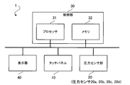
- FIG. 1 is a diagram illustrating an example of a hardware configuration of the touch panel device 1 according to the first embodiment.
- the touch panel device 1 includes a capacitive touch panel 10, a pressure sensor unit 20 that detects a pressing force applied to the operation surface of the touch panel 10 from above, and a control unit 30.
- the touch panel 10 has a display that displays a user interface (UI) image including an operation component (for example, an icon), which is arranged on an operation surface on which a touch operation is performed.
- the touch panel device 1 may include a display 40 that displays information based on the result of the touch operation.
- UI user interface
- the control unit 30 includes, for example, a processor 31 as an information processing unit and a memory 32 as a storage unit that stores information.
- the processor 31 controls the overall operation of the touch panel device 1 by executing a program stored in the memory 32.
- the whole or a part of the control unit 30 may be configured by a control circuit composed of a semiconductor integrated circuit.
- the memory 32 can include various storage devices such as a semiconductor storage device, a hard disk device, and a device that records information on a removable recording medium.
- the memory 32 may store the conductor contact information acquired from the touch panel 10 and the pressure information acquired from the pressure sensor unit 20.
- the control unit 30 performs processing corresponding to the touch operation input on the operation surface of the touch panel 10. Specifically, the control unit 30 is output from the pressure sensor unit 20 in response to a change in capacitance corresponding to the touch operation input on the operation surface of the touch panel 10 and a pressing force applied to the operation surface. And processing based on the pressure detection signal. For example, the control unit 30 transmits an operation signal corresponding to the touch operation input on the operation surface of the touch panel 10 to another device connected to the touch panel device 1 or another device communicable with the touch panel device 1. The other device is, for example, an external device such as a production facility, a vehicle, or a home appliance.
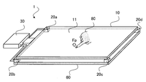
- FIG. 2 is a perspective view schematically showing an example of the structure of the touch panel device 1.
- the touch panel device 1 includes a substrate 60 and four pressure sensors 20 a, 20 b, 20 c, and 20 d that support the touch panel 10 on the substrate 60.
- the substrate 60 may be a part of the casing of the touch panel device 1.
- the control unit 30 is drawn outside the touch panel 10, but the control unit 30 may be a part of the substrate 60 or a part of the circuit board mounted on the substrate 60.
- the pressure sensors 20 a, 20 b, 20 c, and 20 d support the four corners of the touch panel 10 having a square planar shape, respectively.
- the pressure sensors 20a, 20b, 20c, and 20d may support positions other than the corners of the touch panel 10. Further, the planar shape of the touch panel 10 may be a shape other than a quadrangle. Furthermore, the number of pressure sensors that support the touch panel 10 may be three or less or five or more. However, since the accuracy of the calculation result of the pressure coordinate indicating the pressed position decreases as the number of pressure sensors decreases, the number of pressure sensors is desirably four or more.
- the touch panel 10 has an operation surface 11 that is touch-operated by an operator's finger 80.
- a conductor that is, a conductive object
- the capacitance of the contact area of the conductor changes.
- the conductor is, for example, an operation aid such as an operator's finger 80 or a touch pen made of a conductor.
- a water droplet that may adhere to the operation surface 11 is also a conductor.
- the control unit 30 detects the capacitance at each position on the operation surface 11 and acquires the position of the conductor contact region (that is, the two-dimensional coordinates on the operation surface 11).
- the control unit 30 calculates the first coordinates indicating the position of the conductor contact region on the operation surface 11 based on the capacitance at each position on the operation surface 11 of the touch panel 10.
- the conductor contact area is, for example, an area where the electrostatic capacity is larger than a predetermined threshold capacity (ThC).
- the conductor contact region is a “capacitance change region”.
- the first coordinates are also referred to as “capacitance coordinates”.
- the pressure corresponding to the pressing force Fp applied to the operation surface 11 of the touch panel 10 is detected by the pressure sensors 20a, 20b, 20c, and 20d.
- the pressure sensors 20a, 20b, 20c, and 20d are pressure detections that indicate pressure values Fa, Fb, Fc, and Fd corresponding to the magnitude (ie, strength) of the pressing force Fp applied to the operation surface 11 and the pressing position. Output a signal.
- the control unit 30 is a coordinate indicating the pressing force Fp and the pressing position on the operation surface 11 based on the pressure values Fa, Fb, Fc, and Fd indicated by the pressure detection signals output from the pressure sensors 20a, 20b, 20c, and 20d.
- a second coordinate can be calculated.
- the second coordinates are also referred to as “pressure coordinates”.
- FIG. 3 is a functional block diagram schematically showing the touch panel device 1 according to the first embodiment.
- the control unit 30 includes a capacitance detection unit 51, a capacitance coordinate calculation unit 52, a pressure detection unit 53, a pressure coordinate calculation unit 54, a water droplet adhesion determination unit 55, and a touch validity determination unit. 56.
- the capacitance detection unit 51 detects the contact state of the conductor to the operation surface 11 by detecting the capacitance at each position of the operation surface 11 of the touch panel 10.
- the capacitance detection unit 51 provides the capacitance detection value to the capacitance coordinate calculation unit 52.
- the capacitance coordinate calculation unit 52 is based on the capacitance detection value provided from the capacitance detection unit 51, and is a conductor contact that is a region where the capacitance detection value is larger than a predetermined threshold capacitance ThC. First coordinates that are the coordinates of the region are calculated.
- the pressure detection unit 53 receives pressure detection signals output from the pressure sensors 20a, 20b, 20c, and 20d that constitute the pressure sensor unit 20, and calculates pressure coordinates Fa, Fb, Fc, and Fd indicated by the pressure detection signals. Provided to the unit 54 and the water droplet adhesion determination unit 55.
- the pressure coordinate calculation unit 54 is based on the coordinates of the installation positions of the pressure sensors 20a, 20b, 20c, and 20d and the pressure values Fa, Fb, Fc, and Fd acquired from the pressure detection unit 53, and the pressed position on the operation surface 11.
- the second coordinate indicating is calculated.
- the pressure coordinate calculation unit 54 is a first capacitance coordinate calculated by the capacitance coordinate calculation unit 52 in order to calculate a plurality of second coordinates based on the pressure values Fa, Fb, Fc, and Fd. You may refer to the coordinates.
- the water droplet adhesion determination unit 55 has a conductor contact region based on the capacitance detection value provided from the capacitance detection unit 51 and the pressure values Fa, Fb, Fc, and Fd provided from the pressure detection unit 53. It is determined whether or not it is a water droplet adhesion region. For example, the water droplet adhesion determination unit 55 has a conductor contact area, but when the pressing force Fp to the operation surface 11 is equal to or less than a predetermined threshold pressing force ThF, the conductor contact area is determined as the operation surface 11. It is determined that the water droplet adhesion region has water droplets thereon. Note that the water droplet adhesion region may be grounded to GND (that is, a reference potential point such as a person or a housing of the apparatus).
- the touch validity determination unit 56 includes information indicating a water droplet adhesion region acquired from the water droplet adhesion determination unit 55, first coordinates that are coordinates of the conductor contact region acquired from the capacitance coordinate calculation unit 52, and a pressure coordinate calculation unit. Whether the touch operation is valid or invalid is determined on the basis of the second coordinates acquired from 54. Further, the touch validity determination unit 56 considers the calculation error in the pressure coordinate calculation unit 54, and shows the coordinates of the conductor contact region acquired from the capacitance coordinate calculation unit 52 and the water droplet adhesion region acquired from the water droplet adhesion determination unit 55. Based on the information, a process for correcting the second coordinate may be performed. This correction process will be described later with reference to FIG.
- the control unit 30 includes the capacitance at each position of the operation surface 11 provided from the touch panel 10 and the pressure value Fa indicated by the pressure detection signal provided from the pressure sensors 20a, 20b, 20c, and 20d. , Fb, Fc, and Fd operate as follows.
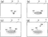
- FIGS. 4A to 4D are diagrams showing examples of the conductor contact areas 101 to 104 and the pressing force detection positions 201 to 204 when a single touch operation is performed on the operation surface 11 of the touch panel 10.
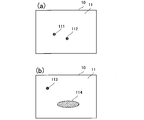
- FIGS. 5A and 5B are diagrams illustrating examples of the conductor contact areas 111 to 114 when a double touch operation is performed on the operation surface 11 of the touch panel 10.
- control unit 30 determines that neither the touch operation with the conductor nor the touch operation with the insulator is performed on the operation surface 11 and there is no water droplet adhesion region. At this time, the control unit 30 does not output an operation signal to the external device.
- Operation example 2 (Condition 2A) This is a case where no conductor contact area is detected on the operation surface 11 and (Condition 2B) a pressing force that presses the operation surface 11 is detected.
- the control unit 30 determines that the touch operation with the conductor is not performed on the operation surface 11 but the touch operation with the insulator is performed on the operation surface 11.
- the control unit 30 does not output an operation signal to the external device.
- the control unit 30 may output an operation signal based on the second coordinates, which are pressure coordinates calculated from the pressure values Fa, Fb, Fc, and Fd, to the external device.
- Operation example 3 (Condition 3A) A case where a conductor contact area is detected on the operation surface 11 and (Condition 3B) a pressing force pressing the operation surface 11 is not detected. In this case, the control unit 30 determines that the operation surface 11 has a water droplet adhesion region and the operation surface 11 is not touched by a conductor. At this time, the control unit 30 does not output an operation signal to the external device.
- control unit 30 outputs an operation signal based on the first coordinates, which are capacitance coordinates calculated from the position coordinates of the conductor contact region 101, to the external device.
- control unit 30 may output an operation signal based on the second coordinates, which are pressure coordinates calculated from the pressure values Fa, Fb, Fc, and Fd, to the external device.
- One conductor contact region 102 is detected on the operation surface 11, and (Condition 4.2B) a pressing force pressing the pressing position 202 of the operation surface 11 is detected, and (Condition 4.2C) The size (for example, area or length) of the conductor contact region 102 is larger than a certain value ThA, and (condition 4.2D) is a pressure coordinate of the pressing position 202 calculated from the pressure values Fa, Fb, Fc, Fd. This is a case where a certain second coordinate exists in the conductor contact region (second region) 102.
- control unit 30 determines that there is a water droplet adhesion region corresponding to the conductor contact region 102 on the operation surface 11 and that the single touch operation is performed in the water droplet adhesion region. At this time, the control part 30 outputs the operation signal based on the 2nd coordinate which is a pressure coordinate to an external apparatus.
- control unit 30 has a water droplet adhesion region corresponding to the conductor contact region 103 on the operation surface 11, and the single touch operation by the conductor is actually performed in the water droplet adhesion region, but the pressure coordinate calculation error This is a case where it is determined that the pressure coordinate is slightly outside the water droplet adhesion region.
- the control unit 30 performs correction for moving the second coordinates, which are pressure coordinates, toward the conductor contact region 103, and outputs an operation signal based on the corrected coordinates to the external device.
- An example of the correction method at this time will be described.
- As a method for calculating pressure coordinates there is a calculation method based on balance of force moments.
- the pressure coordinates have a problem that accuracy (detection resolution) is lower than capacitance coordinates. Therefore, when the pressed position is the end of the conductor contact region 103, the calculated pressure coordinate may be out of the conductor contact region 103. Also in this case, it is considered that the coordinates of the actual touch operation are in the conductor contact area 103 obtained by the capacitance method. Therefore, the pressure coordinate can be corrected by moving the calculated pressure coordinate into the conductor contact region 103 (for example, on the boundary line of the conductor contact region 103). A specific example of the correction method will be described later with reference to FIG.
- control unit 30 has a water droplet adhesion region corresponding to the conductor contact region 104 on the operation surface 11, and the operation surface 11 is not touched by a conductor, but the operation surface 11 is touched by an insulator. It is determined that At this time, the control unit 30 does not output an operation signal to the external device. At this time, the control unit 30 may output an operation signal based on the second coordinates, which are pressure coordinates calculated from the pressure values Fa, Fb, Fc, and Fd, to the external device.
- ⁇ Operation example 5.2> In the operation example 5.2, as shown in FIG. (Condition 5.2A) A plurality of conductor contact regions (seventh and eighth regions) 113 and 114 are detected on the operation surface 11, and (Condition 5.2B) a pressing force for pressing the pressing position of the operation surface 11 is detected. (Condition 5.2C) The size of the conductor contact area 114, which is one of the conductor contact areas 113 and 114, is larger than a certain value ThA, and (Condition 5.2D) pressure values Fa, Fb, Fc, Fd This is a case where the second coordinate, which is the pressure coordinate calculated from the above, exists in the conductor contact region 114.
- control unit 30 determines that there is a water droplet adhesion region corresponding to the conductor contact region 114 on the operation surface 11, and one touch operation of the multi-touch operation is performed in the conductor contact region 114. At this time, the control unit 30 outputs an operation signal based on the first coordinate that is the capacitance coordinate for the coordinates of the touch operation that can be specified in the conductor contact region 113, and the capacitance coordinate is determined by the conductor contact region 114. An operation signal based on the second coordinate that is the pressure coordinate is output only for the operation position that cannot be specified.
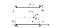
- FIG. 7 and 8 are diagrams illustrating an example of a calculation method of pressure coordinates (x, y) indicating a pressed position when a single touch operation is performed on the operation surface 11 of the touch panel 10.
- FIG. 7 shows a calculation example using the relationship between the moments of force.
- the four corners of the touch panel 10 whose horizontal size is W and whose vertical size is H are supported by pressure sensors 20a, 20b, 20c, and 20d.
- the coordinates of the four corners are (H, 0), (0, 0), (0, H), (W, H).
- a pressure coordinate (x, y) is calculated by a balance equation of force moments in the x-axis direction and the y-axis direction. Specifically, as shown in FIG. 7, when the pressure values detected by the pressure sensors 20a, 20b, 20c, and 20d are Fa, Fb, Fc, and Fd, the force in the x-axis direction and the y-axis direction are measured.
- the moment balance formulas are formulas (1) and (2).
- the coordinates (x, y) can be calculated from the equations (1) and (2).
- the pressure sensor (for example, 20a) having the smallest pressure value among the pressure sensors 20a, 20b, 20c, and 20d is located at the position farthest from the input coordinates, and the pressure value ( For example, when Fa) is extremely smaller than the pressure values (for example, Fb, Fc, Fd) of other pressure sensors (for example, 20b, 20c, 20d), the influence of the pressure sensor 20a is ignored and the pressure sensors 20b, 20c are ignored.
- 20d may be calculated as a balance of the moments of force in the triangle formed by tying 20d.
- 7 and 8 are calculation examples of pressure coordinates when the four corners of the touch panel 10 are supported by the pressure sensors 20a, 20b, 20c, and 20d.
- the number of pressure sensors 20a, 20b, 20c, 20d is increased or the arrangement of the pressure sensors 20a, 20b, 20c, 20d is changed, depending on the number and position of the pressure sensors 20a, 20b, 20c, 20d, What is necessary is just to change a calculation formula.
- a method for calculating pressure coordinates as a regression problem or an evaluation function for inputting an arbitrary coordinate value of the operation surface 11 of the touch panel 10 is used as an evaluation function evaluation result. It is also possible to adopt a method of outputting the coordinate with the smallest obtained numerical value as the pressure coordinate.
- FIG. 9 is a diagram showing a pressure coordinate correction method in the above “Operation Example 4.3”.
- the pressure coordinate of the pressing position 203 obtained by the calculation is outside the conductor contact area 103 that is the water droplet adhesion area and inside the vicinity area 105.
- the accuracy of the first coordinate obtained from the capacitance is higher than the accuracy of the second coordinate, which is the pressure coordinate
- the input coordinate to the operation surface 11 of the touch panel 10 is actually in the conductor contact region 103. It is considered to exist within the range. For this reason, it is desirable to correct the pressure coordinate of the pressing position 203 using the conductor contact region 103.
- the pressure coordinate point of the pressing position 203 and the center point 103a which is the representative point of the conductor contact area 103 are connected by a straight line 300, and the intersection coordinates of the boundary line of the conductor contact area 103 and the straight line 300 are corrected.
- Pressure coordinate 203a is an example of a representative point of the conductor contact region 103.
- the center point 103 a is, for example, the gravity position or the midpoint of the longest axis of the conductor contact region 103.
- the straight line 300 may be determined using a representative point other than the center point 103a.
- FIG. 9 only shows an example of the correction method, and the pressure coordinates may be corrected by other methods.
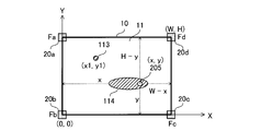
- FIG. 10 is a diagram illustrating an example of calculating pressure coordinates during a multi-touch operation.
- there are two touch operations one point is in the conductor contact region 113, and the other point is in the conductor contact region 114.
- the four corners of the touch panel 10 are supported by the pressure sensors 20a, 20b, 20c, and 20d, and the pressure coordinate of the pressing position 205 is calculated using a balance equation of the moment of force. Can do.
- the coordinates of the conductor contact region 113 can be specified by the capacitance method. Further, with the four pressure sensors 20a, 20b, 20c, and 20d, it is difficult to specify the pressing force at each of the plurality of pressing positions, so that the two touch operations are performed with the same pressing force. Assume. It is also possible to perform calculation on the assumption that the number of pressure sensors is increased and the pressing forces of a plurality of touch operations are different from each other.
- the pressure values detected by the pressure sensors 20a, 20b, 20c, and 20d are Fa, Fb, Fc, and Fd
- the pressing force at the touch operation position (205 in FIG. 10) is Fn
- the touch obtained by the capacitance method is Fn
- the touch obtained by the capacitance method is Fn
- the coordinates of the point (113 in FIG. 10) are (x1, y1)
- the balance equation of the moment of force in the x-axis direction is the equations (3) and (4)
- the moment of force in the y-axis direction The balance formula is formulas (5) and (6).
- X of coordinates (x, y) is obtained from the simultaneous equations of equations (3) and (4), and y of coordinates (x, y) is obtained from the simultaneous equations of equations (5) and (6).
- FIG. 11 is a flowchart showing the operation of the touch panel device 1 according to the first embodiment.
- the control unit 30 detects an input of a capacitance and a pressure value on the touch panel 10.
- step S102 the control unit 30 confirms that both the capacitance and the pressure value are detected.
- the control unit 30 recognizes that the operation surface 11 is touched with an insulator and only the capacitance is detected. (In the case of “Operation Example 1”), it is recognized that a conductor such as a water drop is touching the touch panel, and the input is invalidated in step S110 in any state.
- step S103 the control unit 30 calculates pressure coordinates from the information on the pressure value using the equations (1) and (2).
- step S104 the control unit 30 calculates capacitance coordinates from the capacitance detection result.
- a liquid such as a water droplet adheres to the touch panel and a finger touches the area, such as when the water droplet is in contact with GND, it is not as a point coordinate but is larger than a certain value ThA.
- ThA a conductor contact area is detected.
- information regarding the conductor contact region is held in the storage unit.
- step S105 the control unit 30 determines whether or not a conductor contact area larger than a certain value ThA is detected. If a conductor contact area larger than the certain value ThA is detected, a water droplet adhesion area is detected in step S106. It is determined whether or not. Although water droplets are attached to the end of the touch panel 10, when the touch operation is performed at a position completely different from the conductor contact area, the pressure coordinate and the position of the water drop adhesion area do not overlap at all. As described above, when it can be determined that there is no input from the conductor in the water droplet adhesion region, the control unit 30 does not perform the process of step S106.
- step S107 the control unit 30 performs a single touch process in step S108 or a multi-touch process in step S109 according to the number of conductor contact areas after the water droplet adhesion area in step S106 is excluded. Details of these processes are shown in FIGS.
- FIG. 12 is a flowchart showing a single touch process in the touch panel device according to the first embodiment.
- the control unit 30 determines whether or not the coordinates of the conductor contact area can be specified from the capacitance, and if so, outputs the capacitance coordinates in step S202. This process is the process of “Operation Example 4.1”.
- step S201 when it is difficult to specify the capacitance coordinates, the control unit 30 determines in step S203 whether or not the pressure coordinates exist in the conductor contact region, and if present, the pressure coordinates are determined in step S204. Is output.
- This process is the process of the “operation example 4.2”.
- step S205 When the pressure coordinate is located outside the conductor contact area, the control unit 30 considers the calculation error of the pressure coordinate in step S205, and if the pressure coordinate exists within the vicinity area within a certain distance from the conductor contact area.
- step S206 for example, the pressure coordinate corrected by the correction method described in FIG. 9 is output. This process is the process of “Operation Example 4.3”.
- control unit 30 invalidates the input in step S207 because a touch operation by an insulator is considered. This process is the process of “Operation Example 4.4”.
- FIG. 13 is a flowchart showing the operation of the touch panel device according to the second embodiment.
- the control unit 30 determines whether or not the capacitance coordinates can be specified for all touch operation points, and if possible, outputs the capacitance coordinates in step S302.
- control unit 30 notifies the pressure coordinate calculation unit of the plurality of capacitance coordinates that can be specified and the number of input points in step S303. This process is the process of “Operation Example 5.1”.
- step S304 the control unit 30 obtains pressure coordinates in consideration of the influence of a plurality of touch operation points on the pressure sensors 20a, 20b, 20c, and 20d as a resultant force.
- step S305 the control unit 30 outputs capacitance coordinates and pressure coordinates. This process is the process of the above “Operation Example 5.2”.
- ⁇ 1-3 Effects as described above, according to the touch panel device 1 according to the first embodiment, even when water droplets are present on the operation surface 11 of the touch panel 10, the touch operation is accurately determined. be able to. Therefore, erroneous input can be reduced.
- ⁇ 2 Embodiment 2
- the input is invalidated unless both the capacitance larger than the threshold capacitance ThC and the pressing force Fp larger than the threshold pressing force ThF are detected.
- the touch panel device may output pressure coordinates calculated using the above formulas (1) and (2). This corresponds to “Operation Example 2” in FIG.
- FIG. 14 is a flowchart showing the operation of the touch panel device according to the second embodiment. Steps S401 to S409 in FIG. 14 are the same as steps S101 to S109 in FIG.
- the touch panel device according to the second embodiment is the same as the touch panel device 1 according to the first embodiment in that the processes of steps S410 to S412 in FIG. 11 are performed. Therefore, in the second embodiment, FIG. 1 to FIG. 10, FIG. 12 and FIG. 13 are also referred to.
- step S410 the control unit 30 determines whether or not a capacitance larger than the threshold capacitance ThC has been detected.
- the control unit 30 recognizes that a conductor such as a water drop is in contact with the operation surface 11 of the touch panel 10, and invalidates the input in step S411. . If the control unit 30 does not detect a capacitance larger than the threshold capacitance ThC, that is, if it detects a pressing force Fp larger than the threshold pressing force ThF, it calculates a pressure coordinate in step S412.
- the touch operation can be accurately determined even when water droplets are present on the operation surface 11 of the touch panel 10. Therefore, erroneous input can be reduced.
- operation information based on an input operation using an insulator device can be output.
- ⁇ 3 Embodiment 3
- the method for obtaining the absolute coordinates, which are the pressure coordinates of the pressed position, from the pressure values Fa to Fd has been described.
- the control unit 30 includes the first time point coordinates, which are the pressure coordinates (second coordinates) detected earlier in time, and the pressure coordinates detected later in time (second coordinates). This is a method of obtaining a relative movement amount ( ⁇ x, ⁇ y) based on a difference from a second time point coordinate (second coordinate) and considering the relative movement amount ( ⁇ x, ⁇ y) as the second coordinate.
- the touch panel device according to the third embodiment is the same as the touch panel device according to the first or second embodiment except that a relative movement amount of pressure coordinates is used. Therefore, in Embodiment 3, reference is also made to FIGS.
- FIGS. 15A to 15C are diagrams illustrating the operation of the touch panel device according to the third embodiment.
- FIGS. 15A to 15C show an approximate calculation method of a relative movement amount using a change in pressure coordinates.
- the pressure difference values ⁇ Fx and ⁇ Fy between the detected pressure value and the pressure value detected at an earlier time point are calculated in the x-axis direction and the y-axis direction, and the x Relative movement amounts ⁇ x and ⁇ y are obtained by multiplying the pressure difference value in the axial direction and the y-axis direction by a coefficient ⁇ that is converted into the relative movement amount of the pressure coordinate.
- the pressure values of the pressure sensors 20a, 20b, 20c, and 20d are Fa, Fb, Fc, and Fd, respectively, and the previous pressure values of the pressure sensors 20a, 20b, 20c, and 20d are Fa ′ and Fb′Fc, respectively.
- Fd the conversion coefficient from the pressure value to the movement amount is ⁇
- the relative movement amounts ⁇ x and ⁇ y in the x-axis direction and the y-axis direction are obtained by the equations (7) and (8).
- the conversion coefficient ⁇ is a parameter that should be changed depending on the position of the pressure coordinate. That is, it is desirable to change the value of the conversion coefficient ⁇ according to the range of the water droplet adhesion region and the information on the pressure value.
- FIG. 16 is a flowchart showing the operation of the touch panel device according to the third embodiment.
- FIG. 16 shows processing at the time of detecting coordinates of a single touch operation in the system that calculates the relative movement amounts ⁇ x and ⁇ y using the amount of change in pressure.
- step S501 the control unit 30 determines whether the capacitance coordinates can be specified from the capacitance. If it is possible, the control unit 30 outputs the coordinates calculated by the capacitance method in step S502. In the next step S503, a user interface (UI) operation relating to absolute coordinates is performed.
- UI user interface
- control unit 30 uses the calculation method shown in the equations (7) and (8) in step S504 to perform relative relative to the x-axis direction and the y-axis direction.
- the movement amounts ⁇ x and ⁇ y are output.
- the touch operation can be accurately determined even when water droplets are present on the operation surface 11 of the touch panel 10. Therefore, erroneous input can be reduced.
- operation information based on an input operation using an insulator device can be output.
- ⁇ 4 Modifications.
- an operation signal based on either the second coordinate that is the capacitance coordinate or the first coordinate that is the pressure coordinate is output based on a certain condition.
- the capacitive method when a touch operation is performed on the water droplet adhesion region, it is also possible to regard the center coordinate of the water droplet adhesion region or the point with the highest capacitance change amount as the position of the touch operation. .
- the touch panel device may be controlled.
Landscapes
- Engineering & Computer Science (AREA)
- General Engineering & Computer Science (AREA)
- Theoretical Computer Science (AREA)
- Human Computer Interaction (AREA)
- Physics & Mathematics (AREA)
- General Physics & Mathematics (AREA)
- Position Input By Displaying (AREA)
Abstract
タッチパネル装置(1)は、操作面(11)における導体の接触領域の静電容量が変化するタッチパネル(10)と、操作面(11)に加えられた押圧力と押圧位置に応じた圧力検出信号を出力する圧力センサ部(20)と、静電容量に基づいて操作面(11)における第1の座標を算出し、圧力検出信号が示す圧力値(Fa~Fd)に基づいて操作面(11)における第2の座標を算出する制御部(30)とを備え、制御部(30)は、静電容量が予め定められた閾値容量(ThC)より大きい領域である第1の領域(101)が検出され、且つ第1の領域の大きさが予め定められた一定値(ThA)以下であり、且つ押圧力が予め定められた閾値押圧力(ThF)より大きい場合には、第1の座標に基づく操作信号を出力する。
Description
本発明は、静電容量方式のタッチパネルを有するタッチパネル装置に関する。
様々な種類のタッチ操作(「タッチジェスチャ操作」又は「タッチ入力操作」とも言う。)を判別するために、静電容量方式の第1のタッチパネルと第1のタッチパネルに重ねて配置された抵抗膜方式の第2のタッチパネルとを有するタッチパネル装置の提案がある(例えば、特許文献1参照)。
また、静電容量方式のタッチパネルと、タッチパネルに重ねて配置された透明部材と、透明部材の歪みを検出する押圧検出部とを有し、歪みが閾値より大きい場合にタッチパネルで検出された二次元座標を有効と判定する装置の提案がある(例えば、特許文献2参照)。
しかしながら、抵抗膜方式のタッチパネルは複数の指をタッチパネルに接触させて行うマルチタッチ操作を正確に判定できない。このため、特許文献1に記載の装置は、第1のタッチパネル上に水滴が存在して第1のタッチパネルが正常に機能しない水滴付着領域を有するときに、マルチタッチ操作を正確に判定できないことがあり、誤入力が発生しやすいという問題がある。
また、特許文献2に記載の装置は、タッチパネル上に水滴が付着してタッチパネルが正常に機能しない領域があるときに、水滴付着領域におけるタッチ操作を正確に判定できず、誤入力が発生しやすいという問題がある。
本発明は、上記課題を解決するためになされたものであり、タッチパネル上に水滴が付着している場合であっても、タッチ操作を正確に判定することができるタッチパネル装置を提供することを目的とする。
本発明の一態様に係るタッチパネル装置は、タッチ操作が行われる操作面を有し、前記操作面における導体の接触領域の静電容量が変化するタッチパネルと、前記操作面に加えられた押圧力と押圧位置に応じた圧力検出信号を出力する圧力センサ部と、前記静電容量に基づいて前記操作面における第1の座標を算出し、前記圧力検出信号が示す圧力値に基づいて前記操作面における第2の座標を算出する制御部と、を備え、前記制御部は、前記静電容量が予め定められた閾値容量より大きい領域である第1の領域が検出され、且つ前記第1の領域の大きさが予め定められた一定値以下であり、且つ前記押圧力が予め定められた閾値押圧力より大きい場合には、前記第1の座標に基づく操作信号を出力することを特徴とする。
本発明によれば、タッチパネル上に水滴が付着している場合であっても、タッチ操作を正確に判定することができる。
以下に、本発明の実施の形態に係るタッチパネル装置を、添付図面を参照しながら説明する。以下の実施の形態は、例にすぎず、本発明の範囲内で種々の変更が可能である。
《1》実施の形態1.
《1-1》構成
図1は、実施の形態1に係るタッチパネル装置1のハードウェア構成の例を示す図である。図1に示されるように、タッチパネル装置1は、静電容量方式のタッチパネル10と、タッチパネル10の操作面に上から加えられた押圧力を検出する圧力センサ部20と、制御部30とを備える。タッチパネル10は、タッチ操作が行われる操作面に重ねて配置され、操作部品(例えば、アイコン)などを含むユーザインタフェース(UI)画像を表示するディスプレイを有する。タッチパネル装置1は、タッチ操作の結果に基づく情報を表示する表示器40を備えてもよい。
《1-1》構成
図1は、実施の形態1に係るタッチパネル装置1のハードウェア構成の例を示す図である。図1に示されるように、タッチパネル装置1は、静電容量方式のタッチパネル10と、タッチパネル10の操作面に上から加えられた押圧力を検出する圧力センサ部20と、制御部30とを備える。タッチパネル10は、タッチ操作が行われる操作面に重ねて配置され、操作部品(例えば、アイコン)などを含むユーザインタフェース(UI)画像を表示するディスプレイを有する。タッチパネル装置1は、タッチ操作の結果に基づく情報を表示する表示器40を備えてもよい。
制御部30は、例えば、情報処理部としてのプロセッサ31と、情報を記憶する記憶部としてのメモリ32とを有する。プロセッサ31は、メモリ32に記憶されているプログラムを実行することにより、タッチパネル装置1の全体の動作を制御する。制御部30の全体又は一部は、半導体集積回路からなる制御回路で構成されてもよい。メモリ32は、半導体記憶装置、ハードディスク装置、取り出し可能な記録媒体に情報を記録する装置などの各種の記憶装置を含むことができる。メモリ32は、タッチパネル10から取得した導体接触情報、圧力センサ部20から取得した圧力情報を記憶してもよい。
制御部30は、タッチパネル10の操作面で入力されたタッチ操作に対応する処理を行う。具体的に言えば、制御部30は、タッチパネル10の操作面で入力されたタッチ操作に対応する静電容量の変化と、操作面に加えられる押圧力に対応して圧力センサ部20から出力される圧力検出信号とに基づく処理を行う。例えば、制御部30は、タッチパネル10の操作面で入力されたタッチ操作に対応する操作信号を、タッチパネル装置1に接続された他の機器又はタッチパネル装置1と通信可能な他の機器に送信する。他の機器は、例えば、生産設備、車両、又は家電機器などの外部機器である。
図2は、タッチパネル装置1の構造の例を概略的に示す斜視図である。図2に示されるように、タッチパネル装置1は、基板60と、タッチパネル10を基板60上に支持する4つの圧力センサ20a,20b,20c,20dとを有する。基板60は、タッチパネル装置1の筐体の一部であってもよい。また、図2では、制御部30をタッチパネル10の外側に描いているが、制御部30は基板60の一部又は基板60に搭載された回路基板の一部であってもよい。図2では、圧力センサ20a,20b,20c,20dが、平面形状が四角形であるタッチパネル10の4つの角部をそれぞれ支持している。図2における圧力センサ20a,20b,20c,20dは、図1の圧力センサ部20を構成する。なお、圧力センサ20a,20b,20c,20dは、タッチパネル10の角部以外の位置を支持してもよい。また、タッチパネル10の平面形状は、四角形以外の形状であってもよい。さらに、タッチパネル10を支持する圧力センサの個数は、3個以下又は5個以上とすることも可能である。ただし、圧力センサの個数が少ないほど押圧位置を示す圧力座標の算出結果の精度が低下するので、圧力センサの個数は4個以上であることが望ましい。
図2に示されるように、タッチパネル10は、操作者の指80によってタッチ操作される操作面11を有する。操作面11に導体(すなわち、導電性の物体)が接触しているときには、導体の接触領域の静電容量が変化する。導体は、例えば、操作者の指80又は導体からなるタッチペンなどの操作補助具である。また、操作面11に付着することがある水滴も導体である。制御部30は、操作面11の各位置における静電容量を検出し、導体接触領域の位置(すなわち、操作面11における二次元座標)を取得する。すなわち、制御部30は、タッチパネル10の操作面11の各位置における静電容量に基づいて操作面11における導体接触領域の位置を示す第1の座標を算出する。導体接触領域は、例えば、静電容量が予め定められた閾値容量(ThC)より大きい領域である。導体接触領域は、「静電容量変化領域」である。第1の座標は、「静電容量座標」とも言う。
タッチパネル10の操作面11に加えられた押圧力Fpに対応する圧力は、圧力センサ20a,20b,20c,20dによって検出される。圧力センサ20a,20b,20c,20dは、操作面11に加えられた押圧力Fpの大きさ(すなわち、強さ)と押圧位置とに応じた圧力値Fa,Fb,Fc,Fdを示す圧力検出信号を出力する。制御部30は、圧力センサ20a,20b,20c,20dから出力される圧力検出信号が示す圧力値Fa,Fb,Fc,Fdに基づいて押圧力Fp及び操作面11における押圧位置を示す座標である第2の座標を算出することができる。第2の座標は、「圧力座標」とも言う。
図3は、実施の形態1に係るタッチパネル装置1を概略的に示す機能ブロック図である。図3において、図1に示される構成要素と同一又は対応する構成要素には、図1に示される符号と同じ符号が付される。図3に示されるように、制御部30は、静電容量検出部51、静電容量座標算出部52、圧力検出部53、圧力座標算出部54、水滴付着判定部55、及びタッチ有効判定部56を有する。
静電容量検出部51は、タッチパネル10の操作面11の各位置における静電容量を検出することで、操作面11への導体の接触状態を検出する。静電容量検出部51は、静電容量の検出値を静電容量座標算出部52に提供する。
静電容量座標算出部52は、静電容量検出部51から提供された静電容量の検出値を基に、静電容量の検出値が予め定められた閾値容量ThCより大きい領域である導体接触領域の座標である第1の座標を算出する。
圧力検出部53は、圧力センサ部20を構成する圧力センサ20a,20b,20c,20dから出力される圧力検出信号を受け取り、圧力検出信号が示す圧力値Fa,Fb,Fc,Fdを圧力座標算出部54及び水滴付着判定部55に提供する。
圧力座標算出部54は、圧力センサ20a,20b,20c,20dの設置位置の座標と、圧力検出部53から取得した圧力値Fa,Fb,Fc,Fdとに基づいて、操作面11における押圧位置を示す第2の座標を算出する。圧力座標算出部54は、圧力値Fa,Fb,Fc,Fdに基づいて複数の第2の座標を算出するために、静電容量座標算出部52で算出された静電容量座標である第1の座標を参照してもよい。
水滴付着判定部55は、静電容量検出部51から提供される静電容量の検出値と圧力検出部53から提供される圧力値Fa,Fb,Fc,Fdとに基づいて、導体接触領域が水滴付着領域であるか否かを判定する。例えば、水滴付着判定部55は、導体接触領域が存在するが、操作面11への押圧力Fpが予め定められた閾値押圧力ThF以下である場合には、その導体接触領域は、操作面11上に水滴が存在する水滴付着領域であると判定する。なお、水滴付着領域は、GND(すなわち、人間又は装置の筐体などの基準電位点)に接地されている場合もある。
タッチ有効判定部56は、水滴付着判定部55から取得する水滴付着領域を示す情報と、静電容量座標算出部52から取得する導体接触領域の座標である第1の座標と、圧力座標算出部54から取得する第2の座標とに基づいて、タッチ操作が有効であるか又は無効であるかを判定する。また、タッチ有効判定部56は、圧力座標算出部54における計算誤差を考慮し、静電容量座標算出部52から取得する導体接触領域の座標と水滴付着判定部55から取得する水滴付着領域を示す情報とに基づいて、第2の座標を補正する処理を行ってもよい。この補正処理は、図9を用いて後述される。
《1-2》動作
制御部30は、タッチパネル10から提供される操作面11の各位置における静電容量と、圧力センサ20a,20b,20c,20dから提供される圧力検出信号が示す圧力値Fa,Fb,Fc,Fdとに基づいて、以下のように動作する。
制御部30は、タッチパネル10から提供される操作面11の各位置における静電容量と、圧力センサ20a,20b,20c,20dから提供される圧力検出信号が示す圧力値Fa,Fb,Fc,Fdとに基づいて、以下のように動作する。
図4(a)から(d)は、タッチパネル10の操作面11にシングルタッチ操作を行ったときの導体接触領域101~104及び押圧力の検出位置201~204の例を示す図である。図5(a)及び(b)は、タッチパネル10の操作面11にダブルタッチ操作を行ったときの導体接触領域111~114の例を示す図である。
〈動作例1〉
動作例1は、
(条件1A)操作面11において導体接触領域が検出されず、且つ
(条件1B)操作面11を押圧する押圧力が検出されない、場合である。
「押圧力が検出されない」とは、圧力値Fa,Fb,Fc,Fdに基づく値(例えば、合計値)である押圧力Fpが予め定められた閾値押圧力ThF以下であることである。「押圧力が検出される」とは、押圧力Fpが閾値押圧力ThFより大きいことである。ただし、押圧力の検出の有無の判定は、他の方法で行われてもよい。
この場合には、制御部30は、操作面11に導体によるタッチ操作及び絶縁体によるタッチ操作のいずれも行われておらず、水滴付着領域も無いと判定する。
このとき、制御部30は、外部機器に操作信号を出力しない。
動作例1は、
(条件1A)操作面11において導体接触領域が検出されず、且つ
(条件1B)操作面11を押圧する押圧力が検出されない、場合である。
「押圧力が検出されない」とは、圧力値Fa,Fb,Fc,Fdに基づく値(例えば、合計値)である押圧力Fpが予め定められた閾値押圧力ThF以下であることである。「押圧力が検出される」とは、押圧力Fpが閾値押圧力ThFより大きいことである。ただし、押圧力の検出の有無の判定は、他の方法で行われてもよい。
この場合には、制御部30は、操作面11に導体によるタッチ操作及び絶縁体によるタッチ操作のいずれも行われておらず、水滴付着領域も無いと判定する。
このとき、制御部30は、外部機器に操作信号を出力しない。
〈動作例2〉
動作例2は、
(条件2A)操作面11において導体接触領域が検出されず、且つ
(条件2B)操作面11を押圧する押圧力が検出された、場合である。
この場合には、制御部30は、操作面11に導体によるタッチ操作は行われていないが操作面11に絶縁体によるタッチ操作が行われたと判定する。
このとき、制御部30は、外部機器に操作信号を出力しない。ただし、このとき、制御部30は、圧力値Fa,Fb,Fc,Fdから算出された圧力座標である第2の座標に基づく操作信号を外部機器に出力してもよい。
動作例2は、
(条件2A)操作面11において導体接触領域が検出されず、且つ
(条件2B)操作面11を押圧する押圧力が検出された、場合である。
この場合には、制御部30は、操作面11に導体によるタッチ操作は行われていないが操作面11に絶縁体によるタッチ操作が行われたと判定する。
このとき、制御部30は、外部機器に操作信号を出力しない。ただし、このとき、制御部30は、圧力値Fa,Fb,Fc,Fdから算出された圧力座標である第2の座標に基づく操作信号を外部機器に出力してもよい。
〈動作例3〉
動作例3は、
(条件3A)操作面11において導体接触領域が検出され、且つ
(条件3B)操作面11を押圧する押圧力が検出されない、場合である。
この場合には、制御部30は、操作面11に水滴付着領域が有り、操作面11に導体によるタッチ操作は行われていないと判定する。
このとき、制御部30は、外部機器に操作信号を出力しない。
動作例3は、
(条件3A)操作面11において導体接触領域が検出され、且つ
(条件3B)操作面11を押圧する押圧力が検出されない、場合である。
この場合には、制御部30は、操作面11に水滴付着領域が有り、操作面11に導体によるタッチ操作は行われていないと判定する。
このとき、制御部30は、外部機器に操作信号を出力しない。
〈動作例4.1〉
動作例4.1は、図4(a)に示されるように、
(条件4.1A)操作面11において導体接触領域(第1の領域)101が1つ検出され、且つ
(条件4.1B)操作面11の押圧位置201を押圧する押圧力が検出され、且つ
(条件4.1C)検出された導体接触領域101の大きさ(例えば、面積又は長さなど)が予め定められた閾値である一定値ThA以下である、場合である。
この場合には、制御部30は、操作面11に水滴付着領域は無く、操作面11において導体による正常なシングルタッチ操作が行われたと判定する。
このとき、制御部30は、導体接触領域101の位置座標から算出された静電容量座標である第1の座標に基づく操作信号を外部機器に出力する。ただし、このとき、制御部30は、圧力値Fa,Fb,Fc,Fdから算出された圧力座標である第2の座標に基づく操作信号を外部機器に出力してもよい。
動作例4.1は、図4(a)に示されるように、
(条件4.1A)操作面11において導体接触領域(第1の領域)101が1つ検出され、且つ
(条件4.1B)操作面11の押圧位置201を押圧する押圧力が検出され、且つ
(条件4.1C)検出された導体接触領域101の大きさ(例えば、面積又は長さなど)が予め定められた閾値である一定値ThA以下である、場合である。
この場合には、制御部30は、操作面11に水滴付着領域は無く、操作面11において導体による正常なシングルタッチ操作が行われたと判定する。
このとき、制御部30は、導体接触領域101の位置座標から算出された静電容量座標である第1の座標に基づく操作信号を外部機器に出力する。ただし、このとき、制御部30は、圧力値Fa,Fb,Fc,Fdから算出された圧力座標である第2の座標に基づく操作信号を外部機器に出力してもよい。
〈動作例4.2〉
動作例4.2は、図4(b)に示されるように、
(条件4.2A)操作面11において導体接触領域102が1つ検出され、且つ
(条件4.2B)操作面11の押圧位置202を押圧する押圧力が検出され、且つ
(条件4.2C)導体接触領域102の大きさ(例えば、面積又は長さなど)が一定値ThAより大きく、且つ
(条件4.2D)圧力値Fa,Fb,Fc,Fdから算出された押圧位置202の圧力座標である第2の座標が導体接触領域(第2の領域)102内に存在する、場合である。
この場合には、制御部30は、操作面11に導体接触領域102に対応する水滴付着領域が有り、シングルタッチ操作が水滴付着領域内で行われたと判定する。
このとき、制御部30は、圧力座標である第2の座標に基づく操作信号を外部機器に出力する。
動作例4.2は、図4(b)に示されるように、
(条件4.2A)操作面11において導体接触領域102が1つ検出され、且つ
(条件4.2B)操作面11の押圧位置202を押圧する押圧力が検出され、且つ
(条件4.2C)導体接触領域102の大きさ(例えば、面積又は長さなど)が一定値ThAより大きく、且つ
(条件4.2D)圧力値Fa,Fb,Fc,Fdから算出された押圧位置202の圧力座標である第2の座標が導体接触領域(第2の領域)102内に存在する、場合である。
この場合には、制御部30は、操作面11に導体接触領域102に対応する水滴付着領域が有り、シングルタッチ操作が水滴付着領域内で行われたと判定する。
このとき、制御部30は、圧力座標である第2の座標に基づく操作信号を外部機器に出力する。
〈動作例4.3〉
動作例4.3は、図4(c)に示されるように、
(条件4.3A)操作面11において導体接触領域103が1つ検出され、且つ
(条件4.3B)操作面11の押圧位置203を押圧する押圧力が検出され、且つ
(条件4.3C)導体接触領域103の大きさ(例えば、面積又は長さなど)が一定値ThAより大きく、且つ
(条件4.3D)圧力値Fa,Fb,Fc,Fdから算出された押圧位置203の圧力座標である第2の座標が導体接触領域(第3の領域)103外であって、導体接触領域103から一定距離以内で導体接触領域103を囲う近傍領域105内に存在する、場合である。
この場合は、制御部30は、操作面11に導体接触領域103に対応する水滴付着領域が有り、導体によるシングルタッチ操作は実際には水滴付着領域内で行われたが、圧力座標の算出誤差によって圧力座標が水滴付着領域の少し外側にあると判定した場合である。
このとき、制御部30は、圧力座標である第2の座標を導体接触領域103に向けて移動させる補正を行い、補正後の座標に基づく操作信号を外部機器に出力する。
このときの補正方法の一例を説明する。圧力座標の算出方法として、力のモーメントのつり合いに基づく計算方法があるが、圧力座標は、静電容量座標に比べて精度(検出解像度)が低いことが課題として挙げられる。そのため、押圧位置が導体接触領域103の端部である場合、算出された圧力座標が導体接触領域103の外側に外れることがあり得る。この場合にも、静電容量方式により求めた導体接触領域103内に実際のタッチ操作の座標があると考えられる。このため、算出された圧力座標を導体接触領域103内(例えば、導体接触領域103の境界線上)に移動させることで、圧力座標を補正することができる。補正方法の具体例は、図9を用いて後述する。
動作例4.3は、図4(c)に示されるように、
(条件4.3A)操作面11において導体接触領域103が1つ検出され、且つ
(条件4.3B)操作面11の押圧位置203を押圧する押圧力が検出され、且つ
(条件4.3C)導体接触領域103の大きさ(例えば、面積又は長さなど)が一定値ThAより大きく、且つ
(条件4.3D)圧力値Fa,Fb,Fc,Fdから算出された押圧位置203の圧力座標である第2の座標が導体接触領域(第3の領域)103外であって、導体接触領域103から一定距離以内で導体接触領域103を囲う近傍領域105内に存在する、場合である。
この場合は、制御部30は、操作面11に導体接触領域103に対応する水滴付着領域が有り、導体によるシングルタッチ操作は実際には水滴付着領域内で行われたが、圧力座標の算出誤差によって圧力座標が水滴付着領域の少し外側にあると判定した場合である。
このとき、制御部30は、圧力座標である第2の座標を導体接触領域103に向けて移動させる補正を行い、補正後の座標に基づく操作信号を外部機器に出力する。
このときの補正方法の一例を説明する。圧力座標の算出方法として、力のモーメントのつり合いに基づく計算方法があるが、圧力座標は、静電容量座標に比べて精度(検出解像度)が低いことが課題として挙げられる。そのため、押圧位置が導体接触領域103の端部である場合、算出された圧力座標が導体接触領域103の外側に外れることがあり得る。この場合にも、静電容量方式により求めた導体接触領域103内に実際のタッチ操作の座標があると考えられる。このため、算出された圧力座標を導体接触領域103内(例えば、導体接触領域103の境界線上)に移動させることで、圧力座標を補正することができる。補正方法の具体例は、図9を用いて後述する。
〈動作例4.4〉
動作例4.4は、図4(d)に示されるように、
(条件4.4A)操作面11において導体接触領域(第4の領域)104が1つ検出され、且つ
(条件4.4B)操作面11の押圧位置204を押圧する押圧力が検出され、且つ
(条件4.4C)導体接触領域104の大きさ(例えば、面積又は長さなど)が一定値ThAより大きく、且つ
(条件4.4D)圧力値Fa,Fb,Fc,Fdから算出された圧力座標である第2の座標が導体接触領域104外であって、近傍領域105外に存在する、場合である。
この場合には、制御部30は、操作面11に導体接触領域104に対応する水滴付着領域が有り、操作面11に導体によるタッチ操作は行われていないが絶縁体により操作面11がタッチ操作されていると判定する。
このとき、制御部30は、外部機器に操作信号を出力しない。なお、このとき、制御部30は、圧力値Fa,Fb,Fc,Fdから算出された圧力座標である第2の座標に基づく操作信号を外部機器に出力してもよい。
動作例4.4は、図4(d)に示されるように、
(条件4.4A)操作面11において導体接触領域(第4の領域)104が1つ検出され、且つ
(条件4.4B)操作面11の押圧位置204を押圧する押圧力が検出され、且つ
(条件4.4C)導体接触領域104の大きさ(例えば、面積又は長さなど)が一定値ThAより大きく、且つ
(条件4.4D)圧力値Fa,Fb,Fc,Fdから算出された圧力座標である第2の座標が導体接触領域104外であって、近傍領域105外に存在する、場合である。
この場合には、制御部30は、操作面11に導体接触領域104に対応する水滴付着領域が有り、操作面11に導体によるタッチ操作は行われていないが絶縁体により操作面11がタッチ操作されていると判定する。
このとき、制御部30は、外部機器に操作信号を出力しない。なお、このとき、制御部30は、圧力値Fa,Fb,Fc,Fdから算出された圧力座標である第2の座標に基づく操作信号を外部機器に出力してもよい。
〈動作例5.1〉
動作例5.1は、図5(a)に示されるように、
(条件5.1A)操作面11において複数の導体接触領域(第5及び第6の領域)111,112が検出され、且つ
(条件5.1B)操作面11の押圧位置を押圧する押圧力が検出され、且つ
(条件5.1C)導体接触領域111,112の各々の大きさが一定値ThA以下である、場合である。
この場合には、制御部30は、操作面11に水滴付着領域は無く、導体による複数位置の正常なタッチ操作であるマルチタッチ操作が行われたと判定する。
このとき、制御部30は、複数の導体接触領域111,112から算出された複数の静電容量座標である複数の第1の座標に基づく操作信号を外部機器に出力する。
動作例5.1は、図5(a)に示されるように、
(条件5.1A)操作面11において複数の導体接触領域(第5及び第6の領域)111,112が検出され、且つ
(条件5.1B)操作面11の押圧位置を押圧する押圧力が検出され、且つ
(条件5.1C)導体接触領域111,112の各々の大きさが一定値ThA以下である、場合である。
この場合には、制御部30は、操作面11に水滴付着領域は無く、導体による複数位置の正常なタッチ操作であるマルチタッチ操作が行われたと判定する。
このとき、制御部30は、複数の導体接触領域111,112から算出された複数の静電容量座標である複数の第1の座標に基づく操作信号を外部機器に出力する。
〈動作例5.2〉
動作例5.2は、図5(b)に示されるように、
(条件5.2A)操作面11において複数の導体接触領域(第7及び第8の領域)113,114が検出され、且つ
(条件5.2B)操作面11の押圧位置を押圧する押圧力が検出され、且つ
(条件5.2C)導体接触領域113,114の一方である導体接触領域114の大きさが一定値ThAより大きく、且つ
(条件5.2D)圧力値Fa,Fb,Fc,Fdから算出された圧力座標である第2の座標が導体接触領域114内に存在する、場合である。
この場合には、制御部30は、操作面11に導体接触領域114に対応する水滴付着領域が有り、マルチタッチ操作の内の1つのタッチ操作は導体接触領域114内で行われたと判定する。
このとき、制御部30は、導体接触領域113で特定できるタッチ操作の座標については、静電容量座標である第1の座標に基づく操作信号を出力し、導体接触領域114によって静電容量座標を特定できない操作位置についてのみ圧力座標である第2の座標に基づく操作信号を出力する。
動作例5.2は、図5(b)に示されるように、
(条件5.2A)操作面11において複数の導体接触領域(第7及び第8の領域)113,114が検出され、且つ
(条件5.2B)操作面11の押圧位置を押圧する押圧力が検出され、且つ
(条件5.2C)導体接触領域113,114の一方である導体接触領域114の大きさが一定値ThAより大きく、且つ
(条件5.2D)圧力値Fa,Fb,Fc,Fdから算出された圧力座標である第2の座標が導体接触領域114内に存在する、場合である。
この場合には、制御部30は、操作面11に導体接触領域114に対応する水滴付着領域が有り、マルチタッチ操作の内の1つのタッチ操作は導体接触領域114内で行われたと判定する。
このとき、制御部30は、導体接触領域113で特定できるタッチ操作の座標については、静電容量座標である第1の座標に基づく操作信号を出力し、導体接触領域114によって静電容量座標を特定できない操作位置についてのみ圧力座標である第2の座標に基づく操作信号を出力する。
以上の「動作例1」から「動作例5.2」までの内容を、図6に表形式で簡略化して記載する。
図7及び図8は、タッチパネル10の操作面11にシングルタッチ操作を行ったときの押圧位置を示す圧力座標(x,y)の計算方法の例を示す図である。
図7では、力のモーメントの関係性を用いた算出例を示す。この例では、横方向のサイズがWであり、縦方向のサイズがHであるタッチパネル10の4つの角部が、圧力センサ20a,20b,20c,20dで支持される。4つの角部の座標は、(H,0)、(0,0)、(0,H)、(W,H)である。x軸方向及びy軸方向の力のモーメントのつり合い式により、圧力座標(x,y)を算出する。具体的には、図7に示されるように、圧力センサ20a,20b,20c,20dによって検出された圧力値をFa,Fb,Fc,Fdとした場合、x軸方向及びy軸方向の力のモーメントのつり合い式は、式(1)及び(2)となる。式(1)及び(2)から座標(x,y)を算出することができる。

また、図8に示されるように、圧力センサ20a,20b,20c,20dの内の圧力値が最も小さい圧力センサ(例えば、20a)は、入力座標から最も離れた位置にあり、その圧力値(例えば、Fa)が他の圧力センサ(例えば、20b,20c,20d)の圧力値(例えば、Fb,Fc,Fd)より極端に小さい場合、圧力センサ20aの影響を無視し、圧力センサ20b,20c,20dを結ぶことで形成される三角形内の力のモーメントのつり合いとして算出してもよい。
図7及び図8の例は、タッチパネル10の4つの角部を圧力センサ20a,20b,20c,20dで支持した場合における圧力座標の算出例である。圧力センサ20a,20b,20c,20dの数を増やした場合又は圧力センサ20a,20b,20c,20dの配置を変更した場合は、圧力センサ20a,20b,20c,20dの数及び位置に応じて、算出式を変更すればよい。
以上に示した圧力座標の算出方法の代わりに、回帰問題として圧力座標を算出する方法、又はタッチパネル10の操作面11の任意の座標値を入力する評価関数を用い、評価関数の評価結果として得られた数値が最も小さくなる座標を圧力座標として出力する方法を採用することも可能である。
図9は、上記「動作例4.3」における、圧力座標の補正方法を示す図である。図9では、計算で得られた押圧位置203の圧力座標が、水滴付着領域である導体接触領域103の外側であって近傍領域105の内側にある。しかし、静電容量から得られた第1の座標の精度は圧力座標である第2の座標の精度より高いので、タッチパネル10の操作面11への入力座標は、実際には導体接触領域103の範囲内に存在すると考えられる。このため、導体接触領域103を用いて押圧位置203の圧力座標を補正することが望ましい。具体的には、押圧位置203の圧力座標の点と導体接触領域103の代表点である中心点103aとを直線300で結び、導体接触領域103の境界線と直線300との交点座標を補正後の圧力座標203aとする。ここで、中心点103aは、導体接触領域103の代表点の一例である。中心点103aは、例えば、重力位置、又は導体接触領域103の最も長い軸の中点などである。ただし、中心点103a以外の代表点を用いて直線300を決定してもよい。なお、図9は、補正方法の一例を示しているに過ぎず、他の方法で圧力座標を補正してもよい。
図10は、マルチタッチ操作時において、圧力座標の算出例を示す図である。ここでは、2点のタッチ操作があり、1点は、導体接触領域113内にあり、他の点は導体接触領域114内にある。また、図7と同様に、タッチパネル10の4つの角部は圧力センサ20a,20b,20c,20dで支持されており、力のモーメントのつり合い式を用いて押圧位置205の圧力座標を計算することができる。
このユースケースでは、導体接触領域113の座標は静電容量方式により特定できていることを前提条件とする。また、4つの圧力センサ20a,20b,20c,20dでは、複数点の個々の押圧位置の押圧力を特定することが困難であるから、2つのタッチ操作は同じ強さの押圧力で行われたと仮定する。なお、圧力センサの数を増やし、複数のタッチ操作の押圧力が互いに異なることを前提とした計算も可能である。
圧力センサ20a,20b,20c,20dにより検出された圧力値をFa,Fb,Fc,Fdとし、タッチ操作位置(図10における、205)における押圧力をFnとし、静電容量方式で求めたタッチ点(図10における、113)の座標を(x1,y1)とした場合、x軸方向の力のモーメントのつり合い式は、式(3)及び(4)であり、y軸方向の力のモーメントのつり合い式は式(5)及び(6)である。
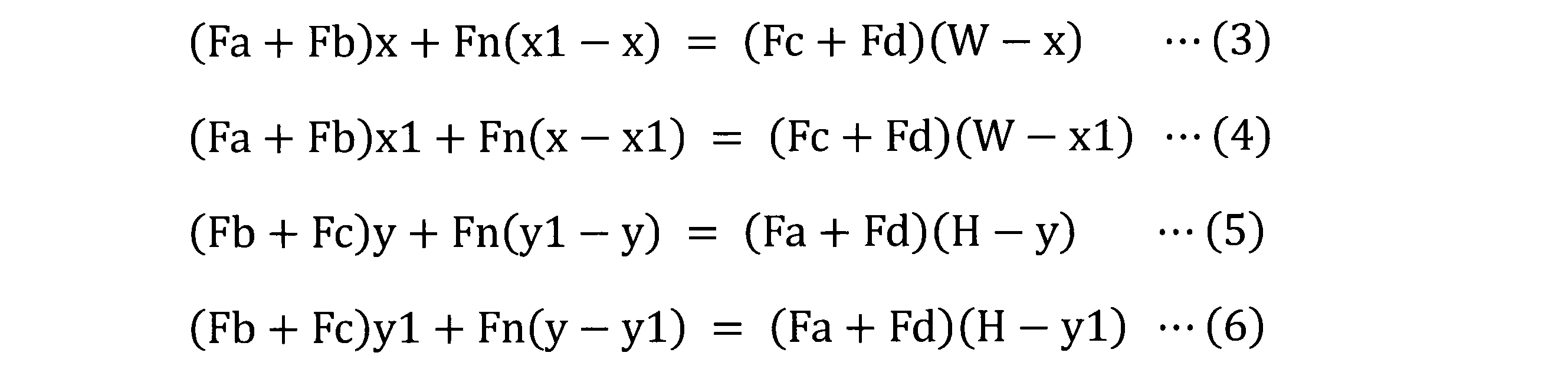
式(3)及び(4)の連立方程式から座標(x,y)のxが求められ、式(5)及び(6)の連立方程式から座標(x,y)のyが求められる。
図11は、実施の形態1に係るタッチパネル装置1の動作を示すフローチャートである。ステップS101において、制御部30は、タッチパネル10における静電容量及び圧力値の入力を検知する。
ステップS102において、制御部30は、静電容量及び圧力値の両方が検出されていることを確認する。制御部30は、押圧力のみが検出された場合(「動作例2」の場合)は、絶縁体で操作面11に触れている状態として認識し、また、静電容量のみが検出された場合(「動作例1」の場合)は、水滴などの導体がタッチパネル上に触れている状態として認識し、何れの状態においてもステップS110で入力を無効とする。
ステップS103において、制御部30は、圧力値の情報から、式(1)及び(2)を用いて圧力座標を算出する。
ステップS104において、制御部30は、静電容量の検出結果から、静電容量座標を算出する。また、水滴などの液体がタッチパネル上に付着し、かつ、その領域に指が触れている等、水滴がGNDに接地するような状態である場合、点座標としてではなく、ある一定値ThAより大きい導体接触領域が検出される。このとき、入力座標を特定することが困難であるため、その導体接触領域に関する情報は、記憶部に保持される。
ステップS105において、制御部30は、一定値ThAより大きい導体接触領域が検出されたか否かを判定し、一定値ThAより大きい導体接触領域が検出された場合には、ステップS106において、水滴付着領域であるか否かを判定する。水滴がタッチパネル10の端部に付着しているが、その導体接触領域とは全く別の位置でタッチ操作をしている場合、圧力座標と水滴付着領域の位置が全く重複しない。このように、制御部30は、水滴付着領域における導体による入力が無いと断定できる場合は、ステップS106の処理を行わない。
ステップS107において、制御部30は、ステップS106における水滴付着領域を除外した後の導体接触領域の数に応じて、ステップS108のシングルタッチ処理又はステップS109のマルチタッチ処理を行う。これらの処理の詳細は、図12及び図13に示される。
図12は、実施の形態1に係るタッチパネル装置におけるシングルタッチ処理を示すフローチャートである。先ず、ステップS201において、制御部30は、静電容量から導体接触領域の座標が特定できるか否かを判定し、できる場合には、ステップS202において静電容量座標を出力する。この処理は、上記「動作例4.1」の処理である。
ステップS201において、静電容量座標の特定が困難である場合、制御部30は、ステップS203において、圧力座標が導体接触領域内に存在するかを判定し、存在する場合は、ステップS204で圧力座標を出力する。この処理は、上記「動作例4.2」の処理である。
圧力座標が導体接触領域外に位置する場合、制御部30は、ステップS205において、圧力座標の算出誤差を考慮し、圧力座標が導体接触領域から一定距離以内である近傍領域内に存在する場合は、ステップS206において、例えば、図9で説明した補正方法により補正された圧力座標を出力する。この処理は、上記「動作例4.3」の処理である。
一定距離以上乖離している場合は、制御部30は、絶縁体によるタッチ操作などが考えられるため、ステップS207において、入力を無効とする。この処理は、上記「動作例4.4」の処理である。
図13は、実施の形態2に係るタッチパネル装置の動作を示すフローチャートである。制御部30は、ステップS301において、全てのタッチ操作点に関して、静電容量座標が特定できるかを判定し、可能である場合、ステップS302において静電容量座標を出力する。
静電容量方式では座標の特定が困難であった場合、制御部30は、ステップS303において、特定できた複数の静電容量座標とその入力点数を圧力座標算出部に通知する。この処理は、上記「動作例5.1」の処理である。
制御部30は、ステップS304において、複数のタッチ操作点が各圧力センサ20a,20b,20c,20dに対し合力となって影響することを考慮し、圧力座標を求める。制御部30は、ステップS305において、静電容量座標及び圧力座標を出力する。この処理は、上記「動作例5.2」の処理である。
《1-3》効果
以上に説明したように、実施の形態1に係るタッチパネル装置1によれば、タッチパネル10の操作面11に水滴が存在する場合であっても、タッチ操作を正確に判定することができる。よって、誤入力を減らすことができる。
以上に説明したように、実施の形態1に係るタッチパネル装置1によれば、タッチパネル10の操作面11に水滴が存在する場合であっても、タッチ操作を正確に判定することができる。よって、誤入力を減らすことができる。
《2》実施の形態2.
実施の形態1においては、閾値容量ThCより大きい静電容量と閾値押圧力ThFより大きい押圧力Fpの両方が検出された場合以外では、入力を無効にした。しかし、タッチパネルの操作面を絶縁体のデバイスでタッチ操作する場合がある。つまり、静電容量を変化させず、押圧力Fpのみが検出される場合である。この場合に、タッチパネル装置は、上記式(1)及び(2)を用いて算出される圧力座標を出力してもよい。これは、図6における「動作例2」に対応する。
実施の形態1においては、閾値容量ThCより大きい静電容量と閾値押圧力ThFより大きい押圧力Fpの両方が検出された場合以外では、入力を無効にした。しかし、タッチパネルの操作面を絶縁体のデバイスでタッチ操作する場合がある。つまり、静電容量を変化させず、押圧力Fpのみが検出される場合である。この場合に、タッチパネル装置は、上記式(1)及び(2)を用いて算出される圧力座標を出力してもよい。これは、図6における「動作例2」に対応する。
図14は、実施の形態2に係るタッチパネル装置の動作を示すフローチャートである。図14におけるステップS401からS409は、図11におけるステップS101からS109と同じである。実施の形態2に係るタッチパネル装置は、図11におけるステップS410からS412の処理を行う点において、実施の形態1に係るタッチパネル装置1と同じである。したがって、実施の形態2においては、図1から図10並びに図12及び図13をも参照する。
ステップS410において、制御部30は、閾値容量ThCより大きい静電容量を検出したか否かを判定する。制御部30は、閾値容量ThCより大きい静電容量を検出した場合には、水滴等の導体がタッチパネル10の操作面11に触れている状態であると認識し、ステップS411で入力を無効にする。制御部30は、閾値容量ThCより大きい静電容量を検出しない場合、すなわち、閾値押圧力ThFより大きい押圧力Fpを検出した場合は、ステップS412において圧力座標を算出する。
以上に説明したように、実施の形態2に係るタッチパネル装置によれば、タッチパネル10の操作面11に水滴が存在する場合であっても、タッチ操作を正確に判定することができる。よって、誤入力を減らすことができる。
さらに、絶縁体のデバイスを用いた入力操作に基づく操作情報を出力することができる。
《3》実施の形態3.
実施の形態1及び2においては、圧力値Fa~Fdから押圧位置の圧力座標である絶対座標を求める方法を説明した。実施の形態3においては、圧力値Fa~Fdの時間軸における変化情報を用いて、タッチ操作による押圧位置の圧力座標を、圧力座標の相対移動量に変換する方法を説明する。つまり、実施の形態3においては、制御部30は、時間的に先に検出された圧力座標(第2の座標)である第1の時点の座標と、時間的に後に検出された圧力座標(第2の座標)である第2の時点の座標との差分に基づく相対移動量(Δx,Δy)を求め、相対移動量(Δx,Δy)を、第2の座標とみなす方法である。
実施の形態1及び2においては、圧力値Fa~Fdから押圧位置の圧力座標である絶対座標を求める方法を説明した。実施の形態3においては、圧力値Fa~Fdの時間軸における変化情報を用いて、タッチ操作による押圧位置の圧力座標を、圧力座標の相対移動量に変換する方法を説明する。つまり、実施の形態3においては、制御部30は、時間的に先に検出された圧力座標(第2の座標)である第1の時点の座標と、時間的に後に検出された圧力座標(第2の座標)である第2の時点の座標との差分に基づく相対移動量(Δx,Δy)を求め、相対移動量(Δx,Δy)を、第2の座標とみなす方法である。
実施の形態3に係るタッチパネル装置は、圧力座標の相対移動量を用いる点以外では、実施の形態1又は2に係るタッチパネル装置と同じである。したがって、実施の形態3においては、図1から図14をも参照する。
図15(a)から(c)は、実施の形態3に係るタッチパネル装置の動作を示す図である。図15(a)から(c)は、圧力座標の変化を用いた相対移動量の近似算出方法を示す。算出方法としては、検出された圧力値と、時間的に早い時点で検出(例えば、前回検出)した圧力値との圧力差分値ΔFxとΔFyとx軸方向及びy軸方向で算出し、そのx軸方向及びy軸方向の圧力差分値に圧力座標の相対移動量に変換する係数αを乗算することで、相対移動量ΔxとΔyを求める。具体的には、圧力センサ20a,20b,20c,20dの圧力値をそれぞれFa,Fb,Fc,Fdとし、前回の圧力センサ20a,20b,20c,20dの圧力値をそれぞれFa′,Fb′Fc′Fd′とし、圧力値から移動量への変換係数をαとした場合、x軸方向及びy軸方向の相対移動量Δx及びΔyは、式(7)及び(8)により求められる。

圧力座標から圧力の検出位置までの距離と、圧力値とは反比例の関係にあるため、変換係数αは、圧力座標の位置によって変更すべきパラメータである。つまり、水滴付着領域の範囲、圧力値の情報に応じて、変換係数αの値を変化させることが望ましい。
図16は、実施の形態3に係るタッチパネル装置の動作を示すフローチャートである。図16は、圧力の変化量を用いて相対移動量Δx、Δyを算出するシステムにおいて、シングルタッチ操作の座標検出時における処理を示す。
ステップS501において、制御部30は、静電容量から静電容量座標を特定できるかを判定する。可能である場合は、制御部30は、ステップS502において、静電容量方式により算出した座標を出力する。次のステップS503においては、絶対座標に関するユーザインタフェース(UI)操作が行われる。
静電容量方式では座標の特定が困難であった場合、制御部30は、ステップS504で、式(7)及び(8)に示した計算方法を用いて、x軸方向及びy軸方向に関する相対移動量Δx及びΔyを出力する。
次のステップS505においては、相対座標(移動量)に対するUI操作が行われる。
以上に説明したように、実施の形態3に係るタッチパネル装置によれば、タッチパネル10の操作面11に水滴が存在する場合であっても、タッチ操作を正確に判定することができる。よって、誤入力を減らすことができる。
さらに、絶縁体のデバイスを用いた入力操作に基づく操作情報を出力することができる。
《4》変形例.
実施の形態1から3においては、ある条件に基づいて静電容量座標である第2の座標又は圧力座標である第1の座標のいずれかに基づく操作信号を出力する例を示した。しかし、静電容量方式では、水滴付着領域にタッチ操作が行われた場合に、水滴付着領域の中心座標又は最も静電容量の変化量が高い点をタッチ操作の位置とみなすことも可能である。このとき、静電容量座標と圧力座標との間には差異が生じる。この差異が小さいほど、静電容量座標及び圧力座標は、精度が高く、信頼性の高い座標であると考えられる。
実施の形態1から3においては、ある条件に基づいて静電容量座標である第2の座標又は圧力座標である第1の座標のいずれかに基づく操作信号を出力する例を示した。しかし、静電容量方式では、水滴付着領域にタッチ操作が行われた場合に、水滴付着領域の中心座標又は最も静電容量の変化量が高い点をタッチ操作の位置とみなすことも可能である。このとき、静電容量座標と圧力座標との間には差異が生じる。この差異が小さいほど、静電容量座標及び圧力座標は、精度が高く、信頼性の高い座標であると考えられる。
そこで、静電容量座標と圧力座標との差異のデータを取得し、静電容量座標と圧力座標の信頼度を定義し、タッチパネル装置に組み込むアプリケーション(アプリケーションソフトウェア)に、定義した信頼度の情報をフィードバックすることで、アプリケーションのインタラクションの幅を広げることが可能である。例えば、高い入力精度を求めないアプリケーションについては信頼度を考慮せずに操作位置の座標を判定し、高い入力精度を要するアプリケーションについては信頼度の情報を考慮に入れて操作位置の座標を判定するようにタッチパネル装置を制御してもよい。
この変形例の特徴を、実施の形態1から3のいずれかに組み合わせることも可能である。
1 タッチパネル装置、 10 タッチパネル、 11 操作面、 20 圧力センサ部、 20a,20b,20c,20d 圧力センサ、 30 制御部、 31 プロセッサ、 32 メモリ、 51 静電容量検出部、 52 静電容量座標算出部、 53 圧力検出部、 54 圧力座標算出部、 55 水滴付着判定部、 56 タッチ有効判定部、 101~104、111~114 導体接触領域、 105 近傍領域、 201~204 押圧位置、 ThC 閾値容量、 ThF 閾値押圧力、 Fp 押圧力、 Fa~Fd 圧力値。
Claims (12)
- タッチ操作が行われる操作面を有し、前記操作面における導体の接触領域の静電容量が変化するタッチパネルと、
前記操作面に加えられた押圧力と押圧位置に応じた圧力検出信号を出力する圧力センサ部と、
前記静電容量に基づいて前記操作面における第1の座標を算出し、前記圧力検出信号が示す圧力値に基づいて前記操作面における第2の座標を算出する制御部と、
を備え、
前記制御部は、
前記静電容量が予め定められた閾値容量より大きい領域である第1の領域が検出され、且つ前記第1の領域の大きさが予め定められた一定値以下であり、且つ前記押圧力が予め定められた閾値押圧力より大きい場合には、前記第1の座標に基づく操作信号を出力する
ことを特徴とするタッチパネル装置。 - 前記制御部は、
前記静電容量が前記閾値容量より大きい領域である第2の領域が検出され、且つ前記第2の領域の大きさが前記一定値より大きく、且つ前記押圧力が前記閾値押圧力より大きい場合には、前記第2の座標に基づく操作信号を出力する
ことを特徴とする請求項1に記載のタッチパネル装置。 - 前記制御部は、
前記静電容量が予め定められた閾値容量より大きい領域である第3の領域が検出され、且つ前記第3の領域の大きさが前記一定値より大きく、且つ前記押圧力が前記閾値押圧力より大きく、且つ前記第2の座標が前記第3の領域外であって前記第3の領域から予め定められた一定距離以内で前記第3の領域を囲う近傍領域内に存在する場合には、前記第2の座標を前記第3の領域に向けて移動させて得られた補正後の第2の座標に基づく操作信号を出力する
ことを特徴とする請求項1又は2に記載のタッチパネル装置。 - 前記制御部は、
前記静電容量が予め定められた閾値容量より大きい領域である第4の領域が検出され、且つ前記第4の領域の大きさが前記一定値より大きく、且つ前記押圧力が前記閾値押圧力より大きく、且つ前記第2の座標が前記第3の領域及び前記近傍領域の外側に存在する場合には、前記第2の座標に基づく操作信号を出力する
ことを特徴とする請求項3に記載のタッチパネル装置。 - 前記制御部は、
前記静電容量が予め定められた閾値容量より大きい領域である第5及び第6の領域が検出され、且つ前記第5及び第6の領域の各々の大きさが前記一定値以下であり、且つ前記押圧力が前記閾値押圧力より大きい場合には、前記第1の座標に基づく操作信号を出力する
ことを特徴とする請求項1から4のいずれか1項に記載のタッチパネル装置。 - 前記制御部は、
前記静電容量が予め定められた閾値容量より大きい領域である第7及び第8の領域が検出され、且つ前記第7の領域の大きさが前記一定値以下であり、且つ前記第8の領域の大きさが前記一定値より大きく、且つ
前記押圧力が前記閾値押圧力より大きい場合には、前記第7の領域については前記第1の座標に基づく操作信号を出力し、前記第8の領域については前記第2の座標に基づく操作信号を出力する
ことを特徴とする請求項1から5のいずれか1項に記載のタッチパネル装置。 - 前記制御部は、
前記静電容量が予め定められた閾値容量より大きい領域が検出されず、且つ前記閾値押圧力より大きい前記押圧力が検出されない場合には、操作信号を出力しない
ことを特徴とする請求項1から6のいずれか1項に記載のタッチパネル装置。 - 前記制御部は、
前記静電容量が予め定められた閾値容量より大きい領域が検出されず、且つ前記閾値押圧力より大きい前記押圧力が検出された場合には、操作信号を出力しない
ことを特徴とする請求項1から7のいずれか1項に記載のタッチパネル装置。 - 前記制御部は、
前記静電容量が予め定められた閾値容量より大きい領域が検出されず、且つ前記閾値押圧力より大きい前記押圧力が検出された場合には、前記第2の座標に基づく操作信号を出力する
ことを特徴とする請求項1から7のいずれか1項に記載のタッチパネル装置。 - 前記制御部は、
前記静電容量が予め定められた閾値容量より大きい領域を検出し、且つ前記閾値押圧力より大きい前記押圧力が検出されない場合には、操作信号を出力しない
ことを特徴とする請求項1から9のいずれか1項に記載のタッチパネル装置。 - 前記制御部は、
時間的に先に検出された前記第2の座標である第1の時点の座標と、時間的に後に検出された前記第2の座標である第2の時点の座標との差分に基づく相対移動量を求め、
前記相対移動量を、前記第2の座標とみなす
ことを特徴とする請求項1から10のいずれか1項に記載のタッチパネル装置。 - 前記圧力センサ部は、前記タッチパネルを支持する複数の圧力センサを有することを特徴とする請求項1から11のいずれか1項に記載のタッチパネル装置。
Priority Applications (5)
| Application Number | Priority Date | Filing Date | Title |
|---|---|---|---|
| JP2019568458A JP6710345B2 (ja) | 2018-01-31 | 2018-01-31 | タッチパネル装置 |
| US16/964,649 US11079873B2 (en) | 2018-01-31 | 2018-01-31 | Touch panel device |
| DE112018006617.7T DE112018006617B4 (de) | 2018-01-31 | 2018-01-31 | Berührungsfeldvorrichtung |
| PCT/JP2018/003125 WO2019150468A1 (ja) | 2018-01-31 | 2018-01-31 | タッチパネル装置 |
| CN201880087450.5A CN111630480B (zh) | 2018-01-31 | 2018-01-31 | 触摸面板装置 |
Applications Claiming Priority (1)
| Application Number | Priority Date | Filing Date | Title |
|---|---|---|---|
| PCT/JP2018/003125 WO2019150468A1 (ja) | 2018-01-31 | 2018-01-31 | タッチパネル装置 |
Publications (1)
| Publication Number | Publication Date |
|---|---|
| WO2019150468A1 true WO2019150468A1 (ja) | 2019-08-08 |
Family
ID=67479962
Family Applications (1)
| Application Number | Title | Priority Date | Filing Date |
|---|---|---|---|
| PCT/JP2018/003125 Ceased WO2019150468A1 (ja) | 2018-01-31 | 2018-01-31 | タッチパネル装置 |
Country Status (5)
| Country | Link |
|---|---|
| US (1) | US11079873B2 (ja) |
| JP (1) | JP6710345B2 (ja) |
| CN (1) | CN111630480B (ja) |
| DE (1) | DE112018006617B4 (ja) |
| WO (1) | WO2019150468A1 (ja) |
Cited By (2)
| Publication number | Priority date | Publication date | Assignee | Title |
|---|---|---|---|---|
| WO2021044533A1 (ja) * | 2019-09-04 | 2021-03-11 | 三菱電機株式会社 | タッチパネル装置、タッチ操作判定方法、及びタッチ操作判定プログラム |
| CN114270299A (zh) * | 2019-09-04 | 2022-04-01 | 三菱电机株式会社 | 触摸面板装置、操作识别方法和操作识别程序 |
Families Citing this family (11)
| Publication number | Priority date | Publication date | Assignee | Title |
|---|---|---|---|---|
| KR102916211B1 (ko) * | 2020-02-10 | 2026-01-23 | 삼성디스플레이 주식회사 | 유기 발광 표시 장치 및 이를 포함하는 전자 기기 |
| CN112099666B (zh) * | 2020-09-10 | 2024-03-29 | 深圳市科航科技发展有限公司 | 一种应用于电容式屏幕的触控方法、系统、终端及存储介质 |
| JP2022071284A (ja) * | 2020-10-28 | 2022-05-16 | シャープ株式会社 | タッチパネルシステム及び表示装置 |
| JP7556501B2 (ja) * | 2020-12-25 | 2024-09-26 | アルプスアルパイン株式会社 | 静電座標入力装置および静電座標算出方法 |
| CN112885215B (zh) * | 2021-01-19 | 2022-12-02 | 四川大学华西医院 | 基于生物动力学胸外心脏按压动态监测的模拟器 |
| CN113460069B (zh) * | 2021-06-29 | 2022-12-30 | 均胜均安汽车电子(上海)有限公司 | 一种方向盘触摸式开关系统及具有其的汽车 |
| TWI786718B (zh) * | 2021-07-09 | 2022-12-11 | 義隆電子股份有限公司 | 觸控板及其力感應資訊校正方法 |
| DE102022101375A1 (de) * | 2022-01-21 | 2023-07-27 | Valeo Schalter Und Sensoren Gmbh | Verfahren zum bestimmen einer position und einer kraft eines fingerdrückens auf einer berührungsfläche und elektronisches gerät, das konfiguriert ist, das verfahren auszuführen |
| CN116243815B (zh) * | 2023-05-10 | 2023-08-08 | 惠科股份有限公司 | 触控面板、显示模组、显示装置以及触控侦测方法 |
| CN120103998B (zh) * | 2023-11-29 | 2026-03-27 | 荣耀终端股份有限公司 | 一种触控方法及电子设备 |
| WO2026005956A1 (en) * | 2024-06-26 | 2026-01-02 | Enovation Controls, Llc | Systems and methods associated with enhancing touch detection on a display using a force sensor |
Citations (4)
| Publication number | Priority date | Publication date | Assignee | Title |
|---|---|---|---|---|
| JP2013168079A (ja) * | 2012-02-16 | 2013-08-29 | Alps Electric Co Ltd | 入力装置及び前記入力装置を用いた重心位置の補正方法 |
| JP2014056421A (ja) * | 2012-09-12 | 2014-03-27 | Fujitsu Ltd | 情報端末装置、タッチ座標決定方法及びタッチ座標決定プログラム |
| JP2015052851A (ja) * | 2013-09-05 | 2015-03-19 | シャープ株式会社 | 操作入力装置、携帯型情報端末、操作入力装置の制御方法、プログラム、及び記録媒体 |
| WO2015046287A1 (ja) * | 2013-09-27 | 2015-04-02 | 株式会社村田製作所 | タッチ式入力装置 |
Family Cites Families (9)
| Publication number | Priority date | Publication date | Assignee | Title |
|---|---|---|---|---|
| JP2014052950A (ja) * | 2012-09-10 | 2014-03-20 | Sharp Corp | 情報端末 |
| JP5506982B1 (ja) * | 2013-05-31 | 2014-05-28 | 富士ソフト株式会社 | タッチ入力装置、タッチ入力補正方法、およびコンピュータプログラム |
| JP6155872B2 (ja) | 2013-06-12 | 2017-07-05 | 富士通株式会社 | 端末装置、入力補正プログラム及び入力補正方法 |
| JP6396478B2 (ja) * | 2013-09-27 | 2018-09-26 | センセル インコーポレイテッドSensel,Inc. | タッチセンサ検出システム及び方法 |
| JP5656307B1 (ja) | 2014-06-20 | 2015-01-21 | パナソニック株式会社 | 電子機器 |
| KR20160104976A (ko) | 2015-02-27 | 2016-09-06 | 삼성전자주식회사 | 터치 모듈, 이를 포함하는 전자 장치 및 이의 운용 방법 |
| JP6250585B2 (ja) * | 2015-04-16 | 2017-12-20 | 株式会社東海理化電機製作所 | 操作検出装置 |
| CN109478113B9 (zh) * | 2016-05-18 | 2022-03-25 | 森赛尔股份有限公司 | 用于检测和确认触摸输入的方法 |
| US10152173B2 (en) * | 2016-08-25 | 2018-12-11 | Parade Technologies, Ltd. | Using 3D touch for signal conditioning and noise reduction on a touch surface |
-
2018
- 2018-01-31 WO PCT/JP2018/003125 patent/WO2019150468A1/ja not_active Ceased
- 2018-01-31 DE DE112018006617.7T patent/DE112018006617B4/de active Active
- 2018-01-31 US US16/964,649 patent/US11079873B2/en not_active Expired - Fee Related
- 2018-01-31 JP JP2019568458A patent/JP6710345B2/ja active Active
- 2018-01-31 CN CN201880087450.5A patent/CN111630480B/zh active Active
Patent Citations (4)
| Publication number | Priority date | Publication date | Assignee | Title |
|---|---|---|---|---|
| JP2013168079A (ja) * | 2012-02-16 | 2013-08-29 | Alps Electric Co Ltd | 入力装置及び前記入力装置を用いた重心位置の補正方法 |
| JP2014056421A (ja) * | 2012-09-12 | 2014-03-27 | Fujitsu Ltd | 情報端末装置、タッチ座標決定方法及びタッチ座標決定プログラム |
| JP2015052851A (ja) * | 2013-09-05 | 2015-03-19 | シャープ株式会社 | 操作入力装置、携帯型情報端末、操作入力装置の制御方法、プログラム、及び記録媒体 |
| WO2015046287A1 (ja) * | 2013-09-27 | 2015-04-02 | 株式会社村田製作所 | タッチ式入力装置 |
Cited By (3)
| Publication number | Priority date | Publication date | Assignee | Title |
|---|---|---|---|---|
| WO2021044533A1 (ja) * | 2019-09-04 | 2021-03-11 | 三菱電機株式会社 | タッチパネル装置、タッチ操作判定方法、及びタッチ操作判定プログラム |
| JPWO2021044533A1 (ja) * | 2019-09-04 | 2021-09-27 | 三菱電機株式会社 | タッチパネル装置、タッチ操作判定方法、及びタッチ操作判定プログラム |
| CN114270299A (zh) * | 2019-09-04 | 2022-04-01 | 三菱电机株式会社 | 触摸面板装置、操作识别方法和操作识别程序 |
Also Published As
| Publication number | Publication date |
|---|---|
| CN111630480A (zh) | 2020-09-04 |
| CN111630480B (zh) | 2023-04-07 |
| DE112018006617T5 (de) | 2020-09-10 |
| DE112018006617B4 (de) | 2022-02-10 |
| JPWO2019150468A1 (ja) | 2020-05-28 |
| US20200371634A1 (en) | 2020-11-26 |
| JP6710345B2 (ja) | 2020-06-17 |
| US11079873B2 (en) | 2021-08-03 |
Similar Documents
| Publication | Publication Date | Title |
|---|---|---|
| JP6710345B2 (ja) | タッチパネル装置 | |
| CN102652300B (zh) | 在多对象感应中测量单个力的系统和方法 | |
| US9207801B2 (en) | Force sensing input device and method for determining force information | |
| US9575562B2 (en) | User interface systems and methods for managing multiple regions | |
| EP3281092B1 (en) | Force-sensitive touch sensor compensation | |
| CN105122197B (zh) | 用于局部力感测的装置和方法 | |
| JP6723226B2 (ja) | 中間遮蔽電極層を採用した力及び近接感知のためのデバイス及び方法 | |
| CN105518596B (zh) | 用于局部力和近距离感测的装置和方法 | |
| CN103329074B (zh) | 用于使用所估计偏转响应来确定物体信息的系统和方法 | |
| CN103270423B (zh) | 用于使用所估计刚性运动响应来确定物体信息的系统和方法 | |
| US20170242539A1 (en) | Use based force auto-calibration | |
| CN101661362A (zh) | 一种多点触摸感应装置 | |
| CN102841702A (zh) | 信息处理装置、显示控制方法以及程序 | |
| JP2018525732A (ja) | タッチ圧力感度補正方法及びコンピュータ読み取り可能な記録媒体 | |
| EP2241955A1 (en) | Electronic touch screen device | |
| CN107980116A (zh) | 悬浮触控感测方法、悬浮触控感测系统及悬浮触控电子设备 | |
| KR101986660B1 (ko) | 터치 센서가 구비된 곡면 디스플레이 장치 | |
| JP2016015181A (ja) | 押圧の度合いによって異なる機能を発動可能なユーザインタフェース装置、プログラム及び機能発動方法 | |
| CN103069364B (zh) | 用于辨别输入物体的系统和方法 | |
| CN202153349U (zh) | 用于电容触摸屏的定位装置、触控系统 | |
| CN105278780B (zh) | 具有混和模式的电容式手指导航装置及其操作方法 | |
| JP5833511B2 (ja) | マルチタッチ状態下で押圧位置を判別可能なユーザインタフェース装置、プログラム及び機能発動方法 | |
| US20080024441A1 (en) | Displacement type pointing device and method | |
| JP2014006765A (ja) | 操作装置 | |
| JP2024175886A (ja) | 入力検出装置、入力検出方法、及び入力検出プログラム |
Legal Events
| Date | Code | Title | Description |
|---|---|---|---|
| 121 | Ep: the epo has been informed by wipo that ep was designated in this application |
Ref document number: 18903599 Country of ref document: EP Kind code of ref document: A1 |
|
| ENP | Entry into the national phase |
Ref document number: 2019568458 Country of ref document: JP Kind code of ref document: A |
|
| 122 | Ep: pct application non-entry in european phase |
Ref document number: 18903599 Country of ref document: EP Kind code of ref document: A1 |