WO2019150422A1 - 空気調和機の室外機 - Google Patents
空気調和機の室外機 Download PDFInfo
- Publication number
- WO2019150422A1 WO2019150422A1 PCT/JP2018/002895 JP2018002895W WO2019150422A1 WO 2019150422 A1 WO2019150422 A1 WO 2019150422A1 JP 2018002895 W JP2018002895 W JP 2018002895W WO 2019150422 A1 WO2019150422 A1 WO 2019150422A1
- Authority
- WO
- WIPO (PCT)
- Prior art keywords
- support component
- wiring support
- holding frame
- wiring
- outdoor unit
- Prior art date
- Legal status (The legal status is an assumption and is not a legal conclusion. Google has not performed a legal analysis and makes no representation as to the accuracy of the status listed.)
- Ceased
Links
Images








Classifications
-
- F—MECHANICAL ENGINEERING; LIGHTING; HEATING; WEAPONS; BLASTING
- F24—HEATING; RANGES; VENTILATING
- F24F—AIR-CONDITIONING; AIR-HUMIDIFICATION; VENTILATION; USE OF AIR CURRENTS FOR SCREENING
- F24F1/00—Room units for air-conditioning, e.g. separate or self-contained units or units receiving primary air from a central station
- F24F1/06—Separate outdoor units, e.g. outdoor unit to be linked to a separate room comprising a compressor and a heat exchanger
- F24F1/20—Electric components for separate outdoor units
- F24F1/22—Arrangement or mounting thereof
Definitions
- the present invention relates to an outdoor unit of an air conditioner, and more particularly to a support structure that supports wiring connected to a substrate.
- a conventional outdoor unit of an air conditioner is provided with a substrate holding frame for holding a substrate for controlling various devices such as a compressor.
- the substrate is connected to various devices via wiring, and a wiring support member that supports the wiring is attached to the substrate holding frame (see, for example, Patent Document 1).
- the wiring support member is separate from the substrate holding frame. By inserting the claw portion provided in the wiring support member into the hole provided in the substrate holding frame, the wiring support member is Attached to the substrate holding frame.
- Patent Document 1 the attachment position of the wiring support member to the substrate holding frame is determined, and the attachment position cannot be changed.
- the size of the substrate varies depending on the model, and the position of drawing the wiring from the substrate also varies. For this reason, when the wiring support member is provided on the substrate holding frame that can hold substrates of different sizes as in Patent Document 2, if the location where the wiring support member is attached to the substrate holding frame is determined, the wiring on the substrate The length from the drawing position to the wiring support member is different. For this reason, even when substrates of different sizes can be held by the substrate holding frame, it is necessary to change the length of the wiring depending on the substrate size, and improvement is necessary from the viewpoint of design versatility.
- the present invention has been made in view of these points, and provides an outdoor unit of an air conditioner including a substrate holding frame that can be used in common for substrates having different substrate sizes and wiring drawing positions. Objective.
- An outdoor unit of an air conditioner according to the present invention is an outdoor unit of an air conditioner provided with an electrical component box, and the electrical component box is a substrate holding frame that holds a substrate and is common to substrates of different sizes. And a wiring support component that is slidably provided on the substrate holding frame and supports the wiring connected to the substrate.
- the wiring support component is slidably provided with respect to the substrate holding frame that is commonly used for substrates of different sizes
- the substrate holding frame is commonly used for substrates having different substrate sizes and wiring drawing positions. Can be used.
- FIG. 3 is a front view of the substrate holding frame of FIG. 2. It is a perspective view of the wiring support component of FIG. FIG. 3 is a schematic enlarged view of a slide guide formed on the front surface of the substrate holding frame of FIG. 2.
- FIG. 3 is a detailed view when a wiring support component is inserted into a slide guide formed on the substrate holding frame of FIG. 2.
- FIG. 3 is a detailed view when a wiring support component is slid with respect to the substrate holding frame of FIG. 2.
- substrate holding frame of FIG. It is a figure which shows the modification of the position holding part in the slide guide of the outdoor unit of the air conditioner which concerns on Embodiment 1 of this invention.
- FIG. 13 is a detailed view when the wiring support component is inserted into the slide guide formed on the substrate holding frame of FIG. 12.
- FIG. 13 is a detailed view when the wiring support component is inserted into the slide guide formed on the substrate holding frame of FIG. 12.
- Embodiment 1 is an exploded perspective view showing an outdoor unit of an air-conditioning apparatus according to Embodiment 1 of the present invention.
- the front, back, right, and left used in the following description mean directions in which the outdoor unit is viewed from the outer panel 1 side in FIG.
- the exterior of the outdoor unit of the air conditioner includes an exterior panel 1 in which a front panel and a left side panel are integrated, a side panel 2 that forms a right side, a top panel 3, and a bottom panel 4. It is comprised by.
- the inside of the outer casing of the outdoor unit is partitioned into a blower chamber 6A and a machine chamber 6B by a partition plate 5.
- a heat exchanger 7 and a motor support 8 are arranged in the blower room 6A.
- the motor support 8 holds the motor to which the propeller fan 9 is attached in front of the heat exchanger 7.
- a compressor 10 In the machine room 6B, a compressor 10, a refrigerant pipe 11, an electrical component box 12, and the like are arranged in the machine room 6B.
- FIG. 2 is an exploded perspective view of the electrical component box of the outdoor unit of the air conditioner according to Embodiment 1 of the present invention.
- FIG. 3 is a detailed view of wiring arrangement in the outdoor unit of the air-conditioning apparatus according to Embodiment 1 of the present invention.
- the electrical component box 12 includes a substrate holding frame 13, a wiring support component 15 that supports wiring connected to the substrate 14, a heat sink support 16 that supports a heat sink, and a cover 17 that covers the upper surface of the substrate holding frame 13. ing.
- the substrate holding frame 13 is a substantially rectangular frame, and has a structure in which the substrate 14 is attached from below with the component mounting surface facing downward. The size of the substrate 14 varies depending on the model, and the position of the terminal block 21 that is the drawing position of the wiring 20 also varies depending on the model.
- the substrate holding frame 13 is commonly used for substrates of different sizes, and the structure that enables holding of substrates of different sizes in the substrate holding frame 13 is not particularly limited in the present invention, and is well known.
- the structure can be adopted. Briefly described as an example, the inner surface of the substrate holding frame 13 is formed such that a maximum size substrate among a plurality of types of substrates can be inserted.
- one horizontal rail guide 130a extending from the inner wall surface of the short side 13a toward the inner wall surface of the other short side 13b is formed here.
- two vertical beam guides 130b extending from the inner wall surface of the long side 13c toward the inner wall surface of the other long side 13d are formed here.
- the substrate 14 is attached to a rectangular region formed by the outer frame of the substrate holding frame 13, the horizontal beam guide 130a, and the vertical beam guide 130b. Therefore, the substrate holding frame 13 can support the substrates 14 having different sizes corresponding to the types of combination patterns of the horizontal beam guides 130a and the vertical beam guides 130b.
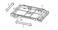
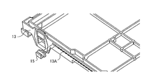
- FIG. 4 is a diagram showing a state in which the wiring support component is assembled to the board holding frame of FIG.
- the arrow a is the left-right direction
- the arrow b is the front-rear direction.
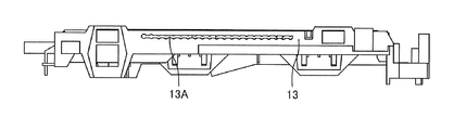
- FIG. 5 is a front view of the substrate holding frame of FIG.
- a slide guide 13A extending in the left-right direction is formed on the front surface of the substrate holding frame 13.
- a wiring support component 15, which is a separate piece from the substrate holding frame 13, is slidably provided on the slide guide 13 ⁇ / b> A.
- FIG. 6 is a perspective view of the wiring support component of FIG.
- the wiring support component 15 supports the wiring 20 connected to the substrate 14, and includes a wiring support portion 15A and a pair of slide protrusions 15B.
- the wiring support portion 15A is positioned outside the substrate holding frame 13 in a state of being attached to the slide guide 13A and supports the wiring, and is configured by a contact portion 15Aa and an L-shaped portion 15Ab.
- the contact portion 15 ⁇ / b> Aa is a portion that contacts the outer surface of the front surface of the substrate holding frame 13.
- the L-shaped portion 15Ab is a portion having an L-shaped cross section that protrudes forward from the lower side of the front surface of the contact portion 15Aa and then extends upward.
- the wiring 20 is supported by the wiring support component 15 by passing through the space between the contact portion 15Aa and the L-shaped portion 15Ab.
- the pair of slide protrusions 15B includes a small-diameter portion 15Ba protruding from the rear surface of the contact portion 15Aa and a large-diameter portion 15Bb integrally provided at the tip of the small-diameter portion 15Ba.
- the wiring support component 15 is slidably attached to the slide guide 13A in the posture shown in FIG. 6, and the pair of slide protrusions 15B are provided on the rear surface of the contact portion 15Aa with a gap in the slide direction. ing.
- the pair of slide protrusions 15B are portions protruding toward the inside of the substrate holding frame 13 from the wiring support portion 15A via the slide guide 13A while being attached to the slide guide 13A.
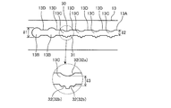
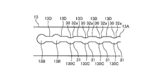
- FIG. 7 is a schematic enlarged view of a slide guide formed on the front surface of the substrate holding frame of FIG.
- the slide guide 13A includes a pair of circular insertion ports 13B, a plurality of position holding portions 13C, and a plurality of guide portions 13D.
- the slide guide 13A includes a through hole or a groove, and the small diameter portion 15Ba of the wiring support component 15 is inserted into the through hole or groove so that the wiring support component 15 slides.
- the small diameter portion 15Ba is an insertion portion that is inserted into the slide guide 13A.
- the slide guide 13A is formed of a through hole.
- the pair of insertion openings 13B are through holes into which the pair of slide protrusions 15B are inserted when the wiring support component 15 is attached to the slide guide 13A.
- the hole diameter l2 is larger than the diameter of the large diameter portion 15Bb of the wiring support component 15. Largely formed.
- the guide portion 13D is a hole for guiding the wiring support component 15 between the pair of insertion ports 13B and the plurality of position holding portions 13C.
- the width l2 in the vertical direction of the guide portion 13D is larger than the diameter of the small diameter portion 15Ba.
- the diameter of the large-diameter portion 15Bb of the slide protrusion 15B is larger than the width l2, and the slide protrusion 15B is prevented from coming off from the guide portion 13D in the front-rear direction when sliding the slide guide 13A.
- the position holding portion 13C is a portion that supports the small-diameter portion 15Ba of the wiring support component 15 and holds the position of the wiring support component 15 with respect to the substrate holding frame 13, and is spaced along the pair of insertion openings 13B in the sliding direction. Are provided.
- the position holding portion 13C is a through-hole through which the small-diameter portion 15Ba is passed, and the inner peripheral surface of the through-hole has an upper surface 30 and a lower surface 31 that are two surfaces facing in a direction orthogonal to the sliding direction.
- One or a plurality of convex portions 32 are formed on each of the upper surface 30 and the lower surface 31.
- the number, size, and position of the convex portions 32 are not particularly limited, but here, one convex portion 32a having an almost circular shape is formed on the upper surface 30, and two small semicircular convex portions 32b are formed on the lower surface 31. Is formed.
- the small diameter portion 15Ba is sandwiched between the plurality of convex portions 32, making it difficult to move in the sliding direction, and holding the position of the wiring support component 15.
- variety 13 of each top part of the convex part 32a and the convex part 32b is the same as the diameter of the small diameter part 15Ba, or a dimension slightly larger.
- FIG. 8 is a detailed view when the wiring support component is inserted into the slide guide formed on the substrate holding frame of FIG.
- FIG. 9 is a detailed view when the wiring support component is slid with respect to the substrate holding frame of FIG.
- FIG. 10 is an explanatory diagram of the positional relationship between the slide guide and the slide protrusion when the wiring support component is slid with respect to the board holding frame of FIG.
- the pair of slide protrusions 15B are inserted from the pair of insertion openings 13B, and the small diameter portion 15Ba is positioned in the slide guide 13A. Then, the small diameter portion 15Ba is slid on the guide portion 13D and is positioned on the position holding portion 13C at a desired position. At this time, as shown in FIG. 10, the small-diameter portion 15Ba is supported by being sandwiched by the plurality of convex portions 32 of the position holding portion 13C at a position lower in the vertical direction than the guide portion 13D. Thereby, the position of the wiring support component 15 in the sliding direction is maintained.
- the position holding portion 13C holds the small diameter portion 15Ba at a position lower than the height position of the guide portion 13D.
- the small diameter portion 15Ba may be held at a position side by side with the guide portion 13D in the sliding direction. .
- the position of the wiring support component 15 can be changed according to the position of the terminal block 21 on the substrate 14, which differs depending on the model. Therefore, the wiring 20 can be shared by properly using the position of the wiring support component 15 for each model.
- the structure which has one wiring support component 15 was shown in FIG. 9, you may use more than one.
- the wiring support component 15 is slidably provided on the substrate holding frame 13 that is commonly used for the substrates 14 of different sizes. For this reason, in addition to being able to hold the substrates 14 having different substrate sizes by the substrate holding frame 13, even if the position of the wiring 20 on the substrate 14 and the position of the terminal block 21 are different depending on the model, the wiring support component The position of 15 can be changed to a position corresponding to the model. That is, since the length from the terminal block 21 to the position of the wiring support component 15 can be adjusted, the length of the wiring 20 can be made common without changing the length of the wiring 20 depending on the model.
- the design specifications can be optimized for each model.
- the shape of the position holding portion 13C in the slide guide 13A is not limited to the shape shown in FIG. 7, and may be the shape shown in FIG.
- FIG. 11 is a diagram illustrating a modification of the position holding unit in the slide guide of the outdoor unit of the air-conditioning apparatus according to Embodiment 1 of the present invention.
- the position holding portion 13 ⁇ / b> C of FIG. 7 two convex portions 32 b are formed on the lower surface 31.
- the position holding unit 130C in FIG. 11 has the two convex portions 32b on the lower surface 31 removed, and has a convex shape that protrudes downward along the convex portion 32a on the upper surface 30.
- the position holding portion 130C has such a shape
- the small diameter portion 15Ba of the wiring support component 15 is slid along the guide portion 13D
- the small diameter portion 15Ba moves to a position lower than the guide portion 13D at the position holding portion 13C. To do. Thereby, it becomes difficult to move the small diameter portion 15Ba in the sliding direction, and the position of the wiring support component 15 in the sliding direction can be held.
- Embodiment 2 is different from the first embodiment in the slide guide 13A and the wiring support component 15. In the following, the second embodiment will be described focusing on the differences from the first embodiment.
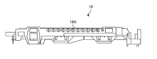
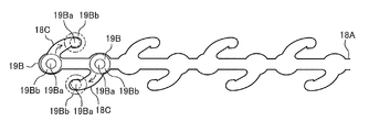
- FIG. 12 is a front view of the substrate holding frame of the outdoor unit for an air-conditioning apparatus according to Embodiment 2 of the present invention.
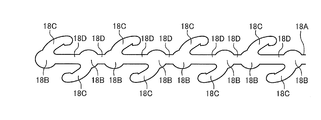
- FIG. 13 is a schematic enlarged view of the slide guide formed on the substrate holding frame of FIG.
- the slide guide 18A of the substrate holding frame 18 according to the second embodiment includes a plurality of pairs of insertion ports 18B, a position holding portion 18C, and a plurality of guide portions 18D provided at intervals in the sliding direction.
- the position holding portion 18C is composed of a pair of locking holes that extend in the upside down direction from each of the pair of insertion ports 18B and that are formed so that the tip portions face each other centering on the center portion of the pair of insertion ports 18B.
- the guide portion 18D is configured by a through hole extending in the sliding direction, and guides the small diameter portion 15Ba of the wiring support component 15 between a plurality of pairs of insertion ports 18B.
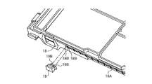
- FIG. 14 is a perspective view of the wiring support component attached to the board holding frame of FIG.
- the wiring support component 19 according to the second embodiment includes a wiring support portion 19A and a pair of slide protrusions 19B.
- the wiring support portion 19A is attached to the slide guide 18A, contacts the outer surface of the front surface of the substrate holding frame 18, and protrudes forward from the lower side of the front surface of the contact portion 19Aa.
- an L-shaped portion 19Ab having an L-shaped cross section.
- the wiring 20 is supported by the wiring support component 19 by passing through the space between the contact portion 19Aa and the L-shaped portion 19Ab.
- the slide protrusion 19B includes a small diameter portion 19Ba protruding from the rear surface of the contact portion 19Aa and a large diameter portion 19Bb provided integrally at the tip of the small diameter portion 19Ba.
- the wiring support component 19 is held by the position holding portion 18C of the substrate holding frame 18 in the posture shown in FIG. 14, and the pair of slide protrusions 19B is orthogonal to the slide direction on the rear surface of the contact portion 19Aa. It is provided at intervals in the direction.
- FIG. 15 is a detailed view when the wiring support component is inserted into the slide guide formed on the substrate holding frame of FIG.
- FIG. 16 is an explanatory diagram of a method of attaching the electrical support component to the board holding frame of FIG.
- FIG. 17 is an explanatory view of the positional relationship between the slide guide and the slide protrusion when the electric support component is attached to the substrate holding frame of FIG. 12 as viewed from the rear surface side of the slide guide.
- FIG. 18 is a diagram illustrating a positional relationship between the slide guide and the slide protrusion when the electric support component is attached to the substrate holding frame of FIG.
- the pair of slide protrusions 19B are as shown by the solid lines in FIGS. 16 (a), 17 (a) and 18 in the posture shown in FIG. Then, it is inserted into a pair of insertion openings 18B arranged at a desired position. Then, the wiring support component 19 is rotated in the direction of the arrow about the center portion of the pair of insertion openings 18B in the sliding direction, and the small-diameter portion 19Ba of the pair of slide protrusions 19B is slid in the position holding portion 18C. Thereby, the wiring support component 19 will be in the state shown by the dotted line of FIG.16 (b), FIG.17 (b), and FIG.
- the small-diameter portion 19Ba of the wiring support component 19 is located at the distal end portion in the rotation direction of the position holding portion 18C.
- the diameter of the tip of the position holding portion 18C is formed to be the same as or slightly larger than the diameter of the small diameter portion 19Ba. Therefore, the small diameter portion 19Ba can be stably held, and the wiring support component 19 is held by the position holding portion 13C.
Landscapes
- Engineering & Computer Science (AREA)
- Chemical & Material Sciences (AREA)
- Combustion & Propulsion (AREA)
- Mechanical Engineering (AREA)
- General Engineering & Computer Science (AREA)
- Air Filters, Heat-Exchange Apparatuses, And Housings Of Air-Conditioning Units (AREA)
- Other Air-Conditioning Systems (AREA)
Abstract
電気品箱を備えた空気調和機の室外機であって、電気品箱は、基板を保持する基板保持枠であって、サイズの異なる基板に共通に用いられる基板保持枠と、基板保持枠にスライド自在に設けられ、基板に接続される配線を支持する配線支持部品とを備えたものである。
Description
本発明は、空気調和機の室外機に関し、更に詳しくは、基板に接続される配線を支持する支持構造に関する。
従来の空気調和機の室外機には、圧縮機等の各種装置を制御するための基板を保持する基板保持枠が備えられている。基板は配線を介して各種装置と接続されており、基板保持枠には配線を支持する配線支持部材が取り付けられている(例えば、特許文献1参照)。特許文献1において配線支持部材は基板保持枠とは別体となっており、基板保持枠に設けられた孔部に、配線支持部材に設けられた爪部を挿入することで、配線支持部材が基板保持枠へ取り付けられる。
また、従来より、サイズの異なる基板でも各々搭載可能で共用することができる基板保持枠を備えた空気調和機の室外機がある(例えば、特許文献2参照)。
特許文献1では、配線支持部材の基板保持枠への取り付け箇所は決まっており、取り付け位置の変更ができない構造となっている。基板のサイズは機種によって様々であり、基板からの配線の引き出し位置も様々である。このため、特許文献2のように、サイズの異なる基板を保持できる基板保持枠に配線支持部材を設ける場合、配線支持部材の基板保持枠への取り付け箇所が決まっていると、基板上の配線の引き出し位置から配線支持部材までの長さが異なる。このため、サイズの異なる基板を基板保持枠で保持できても、配線の長さを基板サイズによって変える必要が生じ、設計汎用性の観点で改善が必要であった。
本発明はこのような点を鑑みなされたもので、基板サイズ及び配線の引き出し位置の異なる基板に共通して用いることが可能な基板保持枠を備えた空気調和機の室外機を提供することを目的とする。
本発明に係る空気調和機の室外機は、電気品箱を備えた空気調和機の室外機であって、電気品箱は、基板を保持する基板保持枠であって、サイズの異なる基板に共通に用いられる基板保持枠と、基板保持枠にスライド自在に設けられ、基板に接続される配線を支持する配線支持部品とを備えたものである。
本発明によれば、異なるサイズの基板に共通に用いられる基板保持枠に対して配線支持部品がスライド自在に設けられているため、基板サイズ及び配線の引き出し位置の異なる基板に基板保持枠を共通して用いることが可能である。
以下、本発明における基板保持枠の配線支持構造の例について、図面を用いて詳細に説明する。
実施の形態1.
実施の形態1について説明をする。図1は、本発明の実施の形態1の空気調和機の室外機を示す分解斜視図である。なお、以下の説明で用いる、前、後、右、左、は、室外機を図1の外郭パネル1側から見た方向を意味している。
図1において、空気調和機の室外機の外郭は、前面パネルと左側面パネルとが一体となった外郭パネル1と、右側面を形成する側面パネル2と、天面パネル3と、底面パネル4とにより構成されている。室外機の外郭の内部は、仕切り板5によって送風機室6Aと機械室6Bとに仕切られている。
実施の形態1について説明をする。図1は、本発明の実施の形態1の空気調和機の室外機を示す分解斜視図である。なお、以下の説明で用いる、前、後、右、左、は、室外機を図1の外郭パネル1側から見た方向を意味している。
図1において、空気調和機の室外機の外郭は、前面パネルと左側面パネルとが一体となった外郭パネル1と、右側面を形成する側面パネル2と、天面パネル3と、底面パネル4とにより構成されている。室外機の外郭の内部は、仕切り板5によって送風機室6Aと機械室6Bとに仕切られている。
送風機室6Aには、熱交換器7と、モーターサポート8とが配置されている。モーターサポート8は、プロペラファン9を取り付けたモーターを、熱交換器7の前方に保持するものである。機械室6Bには、圧縮機10と、冷媒配管11と、電気品箱12等とが配置されている。
図2は、本発明の実施の形態1に係る空気調和機の室外機の電気品箱の分解斜視図である。図3は、本発明の実施の形態1に係る空気調和機の室外機における配線の取り回しの詳細図である。
電気品箱12は、基板保持枠13と、基板14に接続される配線を支持する配線支持部品15と、ヒートシンクを支持するヒートシンクサポート16と、基板保持枠13の上面を覆うカバー17とを備えている。基板保持枠13は、略矩形状の枠体であり、基板14を、部品実装面を下向きにして下方向から取り付けられる構造を有する。基板14は機種によってサイズが異なり、また、配線20の引き出し位置である端子台21の位置も、機種によって異なる。
電気品箱12は、基板保持枠13と、基板14に接続される配線を支持する配線支持部品15と、ヒートシンクを支持するヒートシンクサポート16と、基板保持枠13の上面を覆うカバー17とを備えている。基板保持枠13は、略矩形状の枠体であり、基板14を、部品実装面を下向きにして下方向から取り付けられる構造を有する。基板14は機種によってサイズが異なり、また、配線20の引き出し位置である端子台21の位置も、機種によって異なる。
基板保持枠13は、サイズの異なる基板に共通に用いられるものであって、基板保持枠13においてサイズの異なる基板を保持可能とする構造については、本発明では特に限定するものではなく、公知の構造を採用できる。一例として簡単に説明すると、基板保持枠13は、その内壁面が、複数の種類の基板の内、最大サイズの基板が挿入可能に形成されている。また、短辺13aの内壁面から他方の短辺13bの内壁面に向かって延びている横桟ガイド130aが、ここでは1本形成されている。また、長辺13cの内壁面から他方の長辺13dの内壁面に向かって延びている縦桟ガイド130bが、ここでは2本形成されている。基板14は、基板保持枠13の外枠、横桟ガイド130a及び縦桟ガイド130bで形成される矩形領域に取り付けられる。よって、横桟ガイド130aと各縦桟ガイド130bとの組み合わせパターンの種類だけ、異なるサイズの基板14を基板保持枠13で支持可能となっている。
図4は、図2の基板保持枠に配線支持部品を組み付けた状態を示す図である。図4において矢印aが左右方向、矢印bが前後方向である。図5は、図2の基板保持枠の正面図である。基板保持枠13の前面には、左右方向に延びるスライドガイド13Aが形成されている。スライドガイド13Aには、基板保持枠13とは別ピースである配線支持部品15がスライド自在に設けられている。
図6は、図2の配線支持部品の斜視図である。
配線支持部品15は、基板14に接続される配線20を支持するもので、配線支持部15Aと、一対のスライド突起15Bとを有する。配線支持部15Aは、スライドガイド13Aに取り付けられた状態で基板保持枠13の外方に位置して配線を支持するものであり、当接部15Aaと、L字部15Abとで構成されている。当接部15Aaは、基板保持枠13の前面の外表面に当接する部分である。L字部15Abは、当接部15Aaの前面の下部側から前方に突出した後、上方に延びる断面L字状の部分である。配線20は、当接部15AaとL字部15Abとの間の空間に通されることで配線支持部品15に支持される。
配線支持部品15は、基板14に接続される配線20を支持するもので、配線支持部15Aと、一対のスライド突起15Bとを有する。配線支持部15Aは、スライドガイド13Aに取り付けられた状態で基板保持枠13の外方に位置して配線を支持するものであり、当接部15Aaと、L字部15Abとで構成されている。当接部15Aaは、基板保持枠13の前面の外表面に当接する部分である。L字部15Abは、当接部15Aaの前面の下部側から前方に突出した後、上方に延びる断面L字状の部分である。配線20は、当接部15AaとL字部15Abとの間の空間に通されることで配線支持部品15に支持される。
一対のスライド突起15Bは、当接部15Aaの後面から突出した小径部15Baと、小径部15Baの先端に一体に設けられた大径部15Bbとで構成されている。配線支持部品15は、図6に示した姿勢でスライドガイド13Aにスライド自在に取り付けられるものであり、一対のスライド突起15Bは、当接部15Aaの後面に、スライド方向に間隔を空けて設けられている。また、一対のスライド突起15Bは、スライドガイド13Aに取り付けられた状態で配線支持部15Aからスライドガイド13Aを介して基板保持枠13の内方に向けて突出する部分である。
図7は、図2の基板保持枠の前面に形成されたスライドガイドの概略拡大図である。
スライドガイド13Aは、円形形状の一対の挿入口13Bと、複数の位置保持部13Cと、複数のガイド部13Dとを有する。スライドガイド13Aは、具体的には貫通孔又は溝で構成されており、この貫通孔又は溝に、配線支持部品15の小径部15Baが挿入されて配線支持部品15がスライドするようになっている。つまり、小径部15Baがスライドガイド13Aに挿入される挿入部となっている。以下では、スライドガイド13Aが貫通孔で形成されているものとして説明を行う。
スライドガイド13Aは、円形形状の一対の挿入口13Bと、複数の位置保持部13Cと、複数のガイド部13Dとを有する。スライドガイド13Aは、具体的には貫通孔又は溝で構成されており、この貫通孔又は溝に、配線支持部品15の小径部15Baが挿入されて配線支持部品15がスライドするようになっている。つまり、小径部15Baがスライドガイド13Aに挿入される挿入部となっている。以下では、スライドガイド13Aが貫通孔で形成されているものとして説明を行う。
一対の挿入口13Bは、配線支持部品15をスライドガイド13Aに取り付ける際に一対のスライド突起15Bが挿入される貫通孔であり、孔径l2は、配線支持部品15の大径部15Bbの径よりも大きく形成されている。
ガイド部13Dは、一対の挿入口13B及び複数の位置保持部13Cの間で配線支持部品15を案内するための孔である。ガイド部13Dの上下方向の幅l2は、小径部15Baの径よりも大きい。スライド突起15Bの大径部15Bbの径は、幅l2よりも大きく、スライド突起15Bがスライドガイド13Aをスライドする際にガイド部13Dから前後方向に抜けるのが防止されるようになっている。
位置保持部13Cは、配線支持部品15の小径部15Baを支持して配線支持部品15の基板保持枠13に対する位置を保持する部分であり、一対の挿入口13Bに並んでスライド方向に間隔を空けて複数、設けられている。
位置保持部13Cは、小径部15Baが通される貫通孔であり、この貫通孔の内周面は、スライド方向と直交する方向に対向する2面である上面30と下面31とを有する。上面30と下面31とのそれぞれには、1又は複数の凸部32が形成されている。凸部32の数、大きさ及び位置は特に限定するものではないが、ここでは上面30に大半円形状の1つの凸部32aが形成され、下面31に小半円形状の2つの凸部32bが形成されている。このように複数の凸部32で小径部15Ba挟み込み、スライド方向の移動を行い難くして、配線支持部品15の位置を保持するようになっている。なお、凸部32aと凸部32bとのそれぞれの頂部同士の幅l3は、小径部15Baの径と同じか僅かに大きい寸法となっている。
次に、スライドガイド13Aへの配線支持部品15の取り付け及び配線支持部品15のスライド動作について説明する。
図8は、図2の基板保持枠に形成されたスライドガイドへの配線支持部品の挿入時の詳細図である。図9は、図2の基板保持枠に対して配線支持部品をスライドさせた際の詳細図である。図10は、図2の基板保持枠に対して配線支持部品をスライドさせた際の、スライドガイドとスライド突起との位置関係の説明図である。
配線支持部品15を基板保持枠13に取り付ける際には、まず、一対のスライド突起15Bを、一対の挿入口13Bから挿入して小径部15Baをスライドガイド13A内に位置させる。そして、小径部15Baを、ガイド部13Dにスライドさせ、所望の位置の位置保持部13Cに位置させる。この際、図10に示すように、小径部15Baは、ガイド部13Dよりも上下方向に低い位置で、位置保持部13Cの複数の凸部32によって挟み込まれることで支持される。これにより、配線支持部品15のスライド方向の位置が保持される。なお、ここでは位置保持部13Cが、ガイド部13Dの高さ位置よりも低い位置で小径部15Baを保持するが、ガイド部13Dとスライド方向に横並びの位置で小径部15Baを保持してもよい。
位置保持部13Cはスライド方向に複数設けられているため、機種によって異なる、基板14上の端子台21の位置に応じて配線支持部品15の位置を変更することが可能である。よって、機種ごとに配線支持部品15の位置を使い分けることで、配線20の共通化が可能となる。なお、図9では配線支持部品15が1つである構成を示したが、更に複数用いてもよい。
以上説明したように本実施の形態1によれば、異なるサイズの基板14に共通に用いられる基板保持枠13に対して配線支持部品15をスライド自在に設けた。このため、基板保持枠13で基板サイズが異なる基板14を保持できることに加え、機種によって基板14上の配線20の引き出し位置、具体的には端子台21の位置が異なっていても、配線支持部品15の位置を機種に応じた位置に変更できる。つまり、端子台21から配線支持部品15の位置までの長さを調整できるため、配線20の長さを機種によって異ならせることなく、配線20の長さの共通化が可能である。
また、配線支持部品15の位置及び数を調整することができるため、機種ごとに設計仕様を最適化することができる。
なお、スライドガイド13Aにおける位置保持部13Cの形状は、図7に示した形状に限定されるものではなく、次の図11に示す形状としてもよい。
図11は、本発明の実施の形態1に係る空気調和機の室外機のスライドガイドにおける位置保持部の変形例を示す図である。
上記図7の位置保持部13Cは、下面31に2つの凸部32bが形成されていた。これに対し、図11の位置保持部130Cは、下面31の2つの凸部32bを削除し、上面30の凸部32aに沿う、下方に凸の凸形状とした。位置保持部130Cをこのような形状とした場合、配線支持部品15の小径部15Baをガイド部13Dに沿ってスライドした際、位置保持部13Cで小径部15Baがガイド部13Dよりも低い位置に移動する。これにより、小径部15Baのスライド方向の移動がし難くなり、スライド方向の配線支持部品15の位置を保持することができる。
上記図7の位置保持部13Cは、下面31に2つの凸部32bが形成されていた。これに対し、図11の位置保持部130Cは、下面31の2つの凸部32bを削除し、上面30の凸部32aに沿う、下方に凸の凸形状とした。位置保持部130Cをこのような形状とした場合、配線支持部品15の小径部15Baをガイド部13Dに沿ってスライドした際、位置保持部13Cで小径部15Baがガイド部13Dよりも低い位置に移動する。これにより、小径部15Baのスライド方向の移動がし難くなり、スライド方向の配線支持部品15の位置を保持することができる。
実施の形態2.
実施の形態2は、スライドガイド13A及び配線支持部品15が実施の形態1と異なる。以下、実施の形態2が実施の形態1と異なる部分を中心に説明する。
実施の形態2は、スライドガイド13A及び配線支持部品15が実施の形態1と異なる。以下、実施の形態2が実施の形態1と異なる部分を中心に説明する。
図12は、本発明の実施の形態2に係る空気調和機の室外機の基板保持枠の正面図である。図13は、図12の基板保持枠に形成されたスライドガイドの概略拡大図である。
実施の形態2の基板保持枠18のスライドガイド18Aは、スライド方向に間隔を空けて複数、設けられた一対の挿入口18Bと、位置保持部18Cと、複数のガイド部18Dとを備えている。位置保持部18Cは、一対の挿入口18Bのそれぞれから上下逆方向に延びて先端部が一対の挿入口18Bの中心部を中心として対向するように形成された一対の係止孔で構成されている。ガイド部18Dは、スライド方向に延びた貫通孔で構成され、配線支持部品15の小径部15Baを、複数組の一対の挿入口18B間にガイドするものである。
実施の形態2の基板保持枠18のスライドガイド18Aは、スライド方向に間隔を空けて複数、設けられた一対の挿入口18Bと、位置保持部18Cと、複数のガイド部18Dとを備えている。位置保持部18Cは、一対の挿入口18Bのそれぞれから上下逆方向に延びて先端部が一対の挿入口18Bの中心部を中心として対向するように形成された一対の係止孔で構成されている。ガイド部18Dは、スライド方向に延びた貫通孔で構成され、配線支持部品15の小径部15Baを、複数組の一対の挿入口18B間にガイドするものである。
図14は、図12の基板保持枠に取り付けられる配線支持部品を後方から見た斜視図である。
実施の形態2の配線支持部品19は、配線支持部19Aと、一対のスライド突起19Bとを有する。配線支持部19Aは、スライドガイド18Aに取り付けられた状態で基板保持枠18の前面の外表面に当接する当接部19Aaと、当接部19Aaの前面の下部側から前方に突出した後、上方に延びる断面L字状のL字部19Abとで構成されている。配線20は、当接部19AaとL字部19Abとの間の空間に通されることで配線支持部品19に支持される。
実施の形態2の配線支持部品19は、配線支持部19Aと、一対のスライド突起19Bとを有する。配線支持部19Aは、スライドガイド18Aに取り付けられた状態で基板保持枠18の前面の外表面に当接する当接部19Aaと、当接部19Aaの前面の下部側から前方に突出した後、上方に延びる断面L字状のL字部19Abとで構成されている。配線20は、当接部19AaとL字部19Abとの間の空間に通されることで配線支持部品19に支持される。
スライド突起19Bは、当接部19Aaの後面から突出した小径部19Baと、小径部19Baの先端に一体に設けられた大径部19Bbとで構成されている。配線支持部品19は、図14に示した姿勢で基板保持枠18の位置保持部18Cで保持されるものであり、一対のスライド突起19Bは、当接部19Aaの後面に、スライド方向と直交する方向に間隔を空けて設けられている。
図15は、図12の基板保持枠に形成されたスライドガイドへの配線支持部品の挿入時の詳細図である。図16は、図12の基板保持枠への電気支持部品の取付方法の説明図である。図17は、図12の基板保持枠への電気支持部品の取付時のスライドガイドとスライド突起との位置関係を、スライドガイドの後面側から見た説明図である。図18は、図12の基板保持枠への電気支持部品の取付時のスライドガイドとスライド突起との位置関係を示す図である。
配線支持部品15を基板保持枠13に取り付ける際には、まず、図15に示す姿勢で、一対のスライド突起19Bを、図16(a)、図17(a)及び図18の実線に示すように、所望の位置に配置された一対の挿入口18Bに挿入する。そして、配線支持部品19を、一対の挿入口18Bのスライド方向の中心部を中心として矢印の方向に回転させ、一対のスライド突起19Bの小径部19Baを、位置保持部18C内でスライドさせる。これにより、配線支持部品19は、図16の(b)、図17(b)及び図18の点線で示す状態となる。すなわち、配線支持部品19の小径部19Baが位置保持部18Cの回転方向の先端部に位置する。位置保持部18Cの先端部の径は、小径部19Baの径と同じか僅かに大きい寸法に形成されている。よって、小径部19Baを安定して保持できるようになっており、配線支持部品19が位置保持部13Cに保持される。
本実施の形態2によれば、実施の形態1と同様の効果を得ることができる。
1 外郭パネル、2 側面パネル、3 天面パネル、4 底面パネル、5 仕切り板、6A 送風機室、6B 機械室、7 熱交換器、8 モーターサポート、9 プロペラファン、10 圧縮機、11 冷媒配管、12 電気品箱、13 基板保持枠、13A スライドガイド、13B 挿入口、13C 位置保持部、13D ガイド部、13a 短辺、13b 短辺、13c 長辺、13d 長辺、14 基板、15 配線支持部品、15A 配線支持部、15Aa 当接部、15Ab L字部、15B スライド突起、15Ba 小径部、15Bb 大径部、16 ヒートシンクサポート、17 カバー、18 基板保持枠、18A スライドガイド、18B 挿入口、18C 位置保持部、18D ガイド部、19 配線支持部品、19A 配線支持部、19Aa 当接部、19Ab L字部、19B スライド突起、19Ba 小径部、19Bb 大径部、20 配線、21 端子台、30 上面、31 下面、32 凸部、32a 凸部、32b 凸部、130C 位置保持部、130a 横桟ガイド、130b 縦桟ガイド。
Claims (7)
- 電気品箱を備えた空気調和機の室外機であって、
前記電気品箱は、
基板を保持する基板保持枠であって、サイズの異なる基板に共通に用いられる基板保持枠と、
前記基板保持枠にスライド自在に設けられ、前記基板に接続される配線を支持する配線支持部品とを備えた空気調和機の室外機。 - 前記基板保持枠は、前記配線支持部品をスライド自在に支持するスライドガイドを備え、
前記スライドガイドは、
スライド方向に複数設けられ、前記配線支持部品のスライド方向の位置を保持する位置保持部と、
複数の前記位置保持部間に前記配線支持部品を案内する複数のガイド部とを備えた請求項1記載の空気調和機の室外機。 - 前記スライドガイドは、前記基板保持枠に形成された貫通孔又は溝であり、
前記配線支持部品は、前記スライドガイドにスライド自在に挿入される挿入部を備えた請求項2記載の空気調和機の室外機。 - 前記配線支持部品は、
前記配線支持部品が前記スライドガイドに取り付けられた状態で前記基板保持枠の外方に位置して前記配線を支持する配線支持部と、
前記配線支持部から前記スライドガイドを介して前記基板保持枠の内方に向けて突出した一対の突起とを備え、
前記突起は、
前記挿入部である小径部と、
前記小径部の先端に設けられ、前記基板保持枠の内方に位置して前記小径部よりも径の大きな大径部とを有し、
前記大径部が前記位置保持部及び前記ガイド部から抜けない大きさに構成されている請求項3記載の空気調和機の室外機。 - 前記位置保持部は、スライド方向と直交する方向に対向する2面を有し、前記2面のそれぞれに1又は複数の凸部が形成され、前記各凸部の頂部で前記挿入部を挟むことで前記配線支持部品を保持する請求項3又は請求項4記載の空気調和機の室外機。
- 前記2面のうちの上面に半円形状の1つの前記凸部が形成され、前記2面のうちの下面に、前記上面に形成された前記凸部よりも径の小さい半円形状の2つの凸部が形成されている請求項5記載の空気調和機の室外機。
- 前記スライドガイドは、前記配線支持部品の前記一対のスライド突起が挿入される一対の挿入口をスライド方向に複数備え、
前記位置保持部は、前記一対の挿入口に前記一対のスライド突起が挿入された状態の前記配線支持部品の、前記一対の挿入口の前記スライド方向の中心部を中心とした回転、をガイドする貫通孔又は溝であって、前記配線支持部品が前記位置保持部にガイドされて前記位置保持部の回転方向の先端部で前記小径部を保持することで前記配線支持部品の位置を保持する請求項4記載の空気調和機の室外機。
Priority Applications (3)
| Application Number | Priority Date | Filing Date | Title |
|---|---|---|---|
| JP2019568854A JP6914373B2 (ja) | 2018-01-30 | 2018-01-30 | 空気調和機の室外機 |
| PCT/JP2018/002895 WO2019150422A1 (ja) | 2018-01-30 | 2018-01-30 | 空気調和機の室外機 |
| CN201890000257.9U CN210511942U (zh) | 2018-01-30 | 2018-01-30 | 空调机的室外机 |
Applications Claiming Priority (1)
| Application Number | Priority Date | Filing Date | Title |
|---|---|---|---|
| PCT/JP2018/002895 WO2019150422A1 (ja) | 2018-01-30 | 2018-01-30 | 空気調和機の室外機 |
Publications (1)
| Publication Number | Publication Date |
|---|---|
| WO2019150422A1 true WO2019150422A1 (ja) | 2019-08-08 |
Family
ID=67478002
Family Applications (1)
| Application Number | Title | Priority Date | Filing Date |
|---|---|---|---|
| PCT/JP2018/002895 Ceased WO2019150422A1 (ja) | 2018-01-30 | 2018-01-30 | 空気調和機の室外機 |
Country Status (3)
| Country | Link |
|---|---|
| JP (1) | JP6914373B2 (ja) |
| CN (1) | CN210511942U (ja) |
| WO (1) | WO2019150422A1 (ja) |
Citations (2)
| Publication number | Priority date | Publication date | Assignee | Title |
|---|---|---|---|---|
| JPH0632933U (ja) * | 1992-09-18 | 1994-04-28 | 株式会社富士通ゼネラル | 室外機の電装品箱組立構造 |
| JP2000283503A (ja) * | 1999-03-31 | 2000-10-13 | Fujitsu General Ltd | 空気調和機の室外機 |
-
2018
- 2018-01-30 CN CN201890000257.9U patent/CN210511942U/zh not_active Expired - Fee Related
- 2018-01-30 WO PCT/JP2018/002895 patent/WO2019150422A1/ja not_active Ceased
- 2018-01-30 JP JP2019568854A patent/JP6914373B2/ja not_active Expired - Fee Related
Patent Citations (2)
| Publication number | Priority date | Publication date | Assignee | Title |
|---|---|---|---|---|
| JPH0632933U (ja) * | 1992-09-18 | 1994-04-28 | 株式会社富士通ゼネラル | 室外機の電装品箱組立構造 |
| JP2000283503A (ja) * | 1999-03-31 | 2000-10-13 | Fujitsu General Ltd | 空気調和機の室外機 |
Also Published As
| Publication number | Publication date |
|---|---|
| JP6914373B2 (ja) | 2021-08-04 |
| JPWO2019150422A1 (ja) | 2020-11-19 |
| CN210511942U (zh) | 2020-05-12 |
Similar Documents
| Publication | Publication Date | Title |
|---|---|---|
| JP5527479B2 (ja) | ファンシャーシ、ファンユニット、及び通信装置 | |
| JP5873995B2 (ja) | 空気調和装置の室外ユニット | |
| JP6475040B2 (ja) | 空気調和機の室外機 | |
| US20190285288A1 (en) | Outdoor unit of air-conditioning apparatus | |
| JP2015031504A (ja) | 空気調和機の室外機 | |
| JP5879534B2 (ja) | カバー、及び、空気調和装置の室外ユニット | |
| JP5873994B2 (ja) | 空気調和装置の室外ユニット | |
| KR20150091616A (ko) | 공기조화기의 실외기 | |
| WO2019198151A1 (ja) | 空気調和装置の室外機 | |
| WO2019150422A1 (ja) | 空気調和機の室外機 | |
| CN106211708B (zh) | 机床 | |
| JP2017044403A (ja) | 空気調和機 | |
| JP2018189265A (ja) | 空気調和機の室外機 | |
| JP6988117B2 (ja) | 空気調和機の室内機 | |
| JP2017098031A (ja) | 収納盤、蓄電装置、及び蓄電システム | |
| CN219087690U (zh) | 驱动器和控制柜 | |
| WO2026078976A1 (ja) | ソケット装置及び接続機構 | |
| JP2025173234A (ja) | 空気調和機の室外機及び空気調和機の室外機の組立方法 | |
| JP2024144939A (ja) | 電子機器収納ラック | |
| WO2019030854A1 (ja) | 空気調和機の室内機 | |
| JP6553381B2 (ja) | 電気機器 | |
| JP2018185101A (ja) | 空気調和機の室外機 | |
| JP6639525B2 (ja) | 空気調和装置の室内機 | |
| JP2024144938A (ja) | 冷却構造及びこれを備えた電子機器 | |
| JP4728094B2 (ja) | ヒーターコントロール装置取付構造 |
Legal Events
| Date | Code | Title | Description |
|---|---|---|---|
| 121 | Ep: the epo has been informed by wipo that ep was designated in this application |
Ref document number: 18903240 Country of ref document: EP Kind code of ref document: A1 |
|
| ENP | Entry into the national phase |
Ref document number: 2019568854 Country of ref document: JP Kind code of ref document: A |
|
| NENP | Non-entry into the national phase |
Ref country code: DE |
|
| 122 | Ep: pct application non-entry in european phase |
Ref document number: 18903240 Country of ref document: EP Kind code of ref document: A1 |