WO2019142902A1 - Article façonné en trois dimensions - Google Patents
Article façonné en trois dimensions Download PDFInfo
- Publication number
- WO2019142902A1 WO2019142902A1 PCT/JP2019/001433 JP2019001433W WO2019142902A1 WO 2019142902 A1 WO2019142902 A1 WO 2019142902A1 JP 2019001433 W JP2019001433 W JP 2019001433W WO 2019142902 A1 WO2019142902 A1 WO 2019142902A1
- Authority
- WO
- WIPO (PCT)
- Prior art keywords
- lens
- image
- sheet
- point
- width
- Prior art date
Links
- 239000000463 material Substances 0.000 description 64
- 150000001875 compounds Chemical class 0.000 description 33
- 239000011248 coating agent Substances 0.000 description 23
- 238000000576 coating method Methods 0.000 description 23
- 230000000694 effects Effects 0.000 description 23
- 229920001187 thermosetting polymer Polymers 0.000 description 23
- 238000005034 decoration Methods 0.000 description 21
- 238000007639 printing Methods 0.000 description 18
- 238000000465 moulding Methods 0.000 description 17
- 238000004519 manufacturing process Methods 0.000 description 14
- 239000011295 pitch Substances 0.000 description 14
- 238000007493 shaping process Methods 0.000 description 13
- 229920000642 polymer Polymers 0.000 description 11
- 238000010438 heat treatment Methods 0.000 description 10
- 230000008859 change Effects 0.000 description 9
- OKTJSMMVPCPJKN-UHFFFAOYSA-N Carbon Chemical compound [C] OKTJSMMVPCPJKN-UHFFFAOYSA-N 0.000 description 8
- 229910052799 carbon Inorganic materials 0.000 description 8
- 230000009471 action Effects 0.000 description 7
- 239000004417 polycarbonate Substances 0.000 description 7
- 238000001723 curing Methods 0.000 description 6
- 239000012778 molding material Substances 0.000 description 6
- 239000004634 thermosetting polymer Substances 0.000 description 6
- 238000004804 winding Methods 0.000 description 6
- 238000000034 method Methods 0.000 description 5
- 238000000016 photochemical curing Methods 0.000 description 5
- 239000000758 substrate Substances 0.000 description 5
- XECAHXYUAAWDEL-UHFFFAOYSA-N acrylonitrile butadiene styrene Chemical compound C=CC=C.C=CC#N.C=CC1=CC=CC=C1 XECAHXYUAAWDEL-UHFFFAOYSA-N 0.000 description 4
- 229920000122 acrylonitrile butadiene styrene Polymers 0.000 description 4
- 239000004676 acrylonitrile butadiene styrene Substances 0.000 description 4
- 229920001893 acrylonitrile styrene Polymers 0.000 description 4
- 230000005888 antibody-dependent cellular phagocytosis Effects 0.000 description 4
- 230000006835 compression Effects 0.000 description 4
- 238000007906 compression Methods 0.000 description 4
- 239000003365 glass fiber Substances 0.000 description 4
- 239000007788 liquid Substances 0.000 description 4
- 230000007246 mechanism Effects 0.000 description 4
- 239000000203 mixture Substances 0.000 description 4
- SCUZVMOVTVSBLE-UHFFFAOYSA-N prop-2-enenitrile;styrene Chemical compound C=CC#N.C=CC1=CC=CC=C1 SCUZVMOVTVSBLE-UHFFFAOYSA-N 0.000 description 4
- 229920005992 thermoplastic resin Polymers 0.000 description 4
- 239000002023 wood Substances 0.000 description 4
- 230000005540 biological transmission Effects 0.000 description 3
- 230000000052 comparative effect Effects 0.000 description 3
- 238000005520 cutting process Methods 0.000 description 3
- 239000007789 gas Substances 0.000 description 3
- 229920000139 polyethylene terephthalate Polymers 0.000 description 3
- 239000005020 polyethylene terephthalate Substances 0.000 description 3
- 238000003825 pressing Methods 0.000 description 3
- 230000032258 transport Effects 0.000 description 3
- 238000011144 upstream manufacturing Methods 0.000 description 3
- 125000000391 vinyl group Chemical group [H]C([*])=C([H])[H] 0.000 description 3
- NIXOWILDQLNWCW-UHFFFAOYSA-M Acrylate Chemical compound [O-]C(=O)C=C NIXOWILDQLNWCW-UHFFFAOYSA-M 0.000 description 2
- 238000005033 Fourier transform infrared spectroscopy Methods 0.000 description 2
- VEBCLRKUSAGCDF-UHFFFAOYSA-N ac1mi23b Chemical compound C1C2C3C(COC(=O)C=C)CCC3C1C(COC(=O)C=C)C2 VEBCLRKUSAGCDF-UHFFFAOYSA-N 0.000 description 2
- NIXOWILDQLNWCW-UHFFFAOYSA-N acrylic acid group Chemical group C(C=C)(=O)O NIXOWILDQLNWCW-UHFFFAOYSA-N 0.000 description 2
- 239000000956 alloy Substances 0.000 description 2
- 229910045601 alloy Inorganic materials 0.000 description 2
- 230000001588 bifunctional effect Effects 0.000 description 2
- 230000015572 biosynthetic process Effects 0.000 description 2
- IISBACLAFKSPIT-UHFFFAOYSA-N bisphenol A Chemical compound C=1C=C(O)C=CC=1C(C)(C)C1=CC=C(O)C=C1 IISBACLAFKSPIT-UHFFFAOYSA-N 0.000 description 2
- 238000000748 compression moulding Methods 0.000 description 2
- 230000007423 decrease Effects 0.000 description 2
- 201000003373 familial cold autoinflammatory syndrome 3 Diseases 0.000 description 2
- 230000012447 hatching Effects 0.000 description 2
- 239000004579 marble Substances 0.000 description 2
- 230000003287 optical effect Effects 0.000 description 2
- 239000003973 paint Substances 0.000 description 2
- 239000012994 photoredox catalyst Substances 0.000 description 2
- 229920003023 plastic Polymers 0.000 description 2
- 239000004033 plastic Substances 0.000 description 2
- 239000007787 solid Substances 0.000 description 2
- 238000003856 thermoforming Methods 0.000 description 2
- 238000002834 transmittance Methods 0.000 description 2
- 229920000049 Carbon (fiber) Polymers 0.000 description 1
- 229920002284 Cellulose triacetate Polymers 0.000 description 1
- UFHFLCQGNIYNRP-UHFFFAOYSA-N Hydrogen Chemical compound [H][H] UFHFLCQGNIYNRP-UHFFFAOYSA-N 0.000 description 1
- GWEVSGVZZGPLCZ-UHFFFAOYSA-N Titan oxide Chemical compound O=[Ti]=O GWEVSGVZZGPLCZ-UHFFFAOYSA-N 0.000 description 1
- 206010047571 Visual impairment Diseases 0.000 description 1
- XLOMVQKBTHCTTD-UHFFFAOYSA-N Zinc monoxide Chemical compound [Zn]=O XLOMVQKBTHCTTD-UHFFFAOYSA-N 0.000 description 1
- NNLVGZFZQQXQNW-ADJNRHBOSA-N [(2r,3r,4s,5r,6s)-4,5-diacetyloxy-3-[(2s,3r,4s,5r,6r)-3,4,5-triacetyloxy-6-(acetyloxymethyl)oxan-2-yl]oxy-6-[(2r,3r,4s,5r,6s)-4,5,6-triacetyloxy-2-(acetyloxymethyl)oxan-3-yl]oxyoxan-2-yl]methyl acetate Chemical compound O([C@@H]1O[C@@H]([C@H]([C@H](OC(C)=O)[C@H]1OC(C)=O)O[C@H]1[C@@H]([C@@H](OC(C)=O)[C@H](OC(C)=O)[C@@H](COC(C)=O)O1)OC(C)=O)COC(=O)C)[C@@H]1[C@@H](COC(C)=O)O[C@@H](OC(C)=O)[C@H](OC(C)=O)[C@H]1OC(C)=O NNLVGZFZQQXQNW-ADJNRHBOSA-N 0.000 description 1
- XAGFODPZIPBFFR-UHFFFAOYSA-N aluminium Chemical compound [Al] XAGFODPZIPBFFR-UHFFFAOYSA-N 0.000 description 1
- 229910052782 aluminium Inorganic materials 0.000 description 1
- 239000004917 carbon fiber Substances 0.000 description 1
- 239000002131 composite material Substances 0.000 description 1
- 230000007812 deficiency Effects 0.000 description 1
- 239000000975 dye Substances 0.000 description 1
- 238000005516 engineering process Methods 0.000 description 1
- 230000002708 enhancing effect Effects 0.000 description 1
- 230000001747 exhibiting effect Effects 0.000 description 1
- PCHJSUWPFVWCPO-UHFFFAOYSA-N gold Chemical compound [Au] PCHJSUWPFVWCPO-UHFFFAOYSA-N 0.000 description 1
- 239000010931 gold Substances 0.000 description 1
- 229910052737 gold Inorganic materials 0.000 description 1
- 230000020169 heat generation Effects 0.000 description 1
- 229910052739 hydrogen Inorganic materials 0.000 description 1
- 239000001257 hydrogen Substances 0.000 description 1
- 230000006872 improvement Effects 0.000 description 1
- 230000001678 irradiating effect Effects 0.000 description 1
- VNWKTOKETHGBQD-UHFFFAOYSA-N methane Chemical compound C VNWKTOKETHGBQD-UHFFFAOYSA-N 0.000 description 1
- 239000003607 modifier Substances 0.000 description 1
- 239000000178 monomer Substances 0.000 description 1
- 230000000149 penetrating effect Effects 0.000 description 1
- 239000005011 phenolic resin Substances 0.000 description 1
- 239000000049 pigment Substances 0.000 description 1
- 229920000515 polycarbonate Polymers 0.000 description 1
- -1 polyethylene terephthalate Polymers 0.000 description 1
- 230000008569 process Effects 0.000 description 1
- 239000004576 sand Substances 0.000 description 1
- 239000002904 solvent Substances 0.000 description 1
- 238000010183 spectrum analysis Methods 0.000 description 1
- 230000000007 visual effect Effects 0.000 description 1
Images


Classifications
-
- B—PERFORMING OPERATIONS; TRANSPORTING
- B44—DECORATIVE ARTS
- B44F—SPECIAL DESIGNS OR PICTURES
- B44F1/00—Designs or pictures characterised by special or unusual light effects
- B44F1/02—Designs or pictures characterised by special or unusual light effects produced by reflected light, e.g. matt surfaces, lustrous surfaces
- B44F1/04—Designs or pictures characterised by special or unusual light effects produced by reflected light, e.g. matt surfaces, lustrous surfaces after passage through surface layers, e.g. pictures with mirrors on the back
-
- G—PHYSICS
- G02—OPTICS
- G02B—OPTICAL ELEMENTS, SYSTEMS OR APPARATUS
- G02B30/00—Optical systems or apparatus for producing three-dimensional [3D] effects, e.g. stereoscopic images
- G02B30/20—Optical systems or apparatus for producing three-dimensional [3D] effects, e.g. stereoscopic images by providing first and second parallax images to an observer's left and right eyes
- G02B30/26—Optical systems or apparatus for producing three-dimensional [3D] effects, e.g. stereoscopic images by providing first and second parallax images to an observer's left and right eyes of the autostereoscopic type
- G02B30/27—Optical systems or apparatus for producing three-dimensional [3D] effects, e.g. stereoscopic images by providing first and second parallax images to an observer's left and right eyes of the autostereoscopic type involving lenticular arrays
- G02B30/29—Optical systems or apparatus for producing three-dimensional [3D] effects, e.g. stereoscopic images by providing first and second parallax images to an observer's left and right eyes of the autostereoscopic type involving lenticular arrays characterised by the geometry of the lenticular array, e.g. slanted arrays, irregular arrays or arrays of varying shape or size
-
- B—PERFORMING OPERATIONS; TRANSPORTING
- B29—WORKING OF PLASTICS; WORKING OF SUBSTANCES IN A PLASTIC STATE IN GENERAL
- B29C—SHAPING OR JOINING OF PLASTICS; SHAPING OF MATERIAL IN A PLASTIC STATE, NOT OTHERWISE PROVIDED FOR; AFTER-TREATMENT OF THE SHAPED PRODUCTS, e.g. REPAIRING
- B29C59/00—Surface shaping of articles, e.g. embossing; Apparatus therefor
- B29C59/02—Surface shaping of articles, e.g. embossing; Apparatus therefor by mechanical means, e.g. pressing
-
- B—PERFORMING OPERATIONS; TRANSPORTING
- B44—DECORATIVE ARTS
- B44F—SPECIAL DESIGNS OR PICTURES
- B44F1/00—Designs or pictures characterised by special or unusual light effects
- B44F1/08—Designs or pictures characterised by special or unusual light effects characterised by colour effects
- B44F1/10—Changing, amusing, or secret pictures
-
- B—PERFORMING OPERATIONS; TRANSPORTING
- B60—VEHICLES IN GENERAL
- B60K—ARRANGEMENT OR MOUNTING OF PROPULSION UNITS OR OF TRANSMISSIONS IN VEHICLES; ARRANGEMENT OR MOUNTING OF PLURAL DIVERSE PRIME-MOVERS IN VEHICLES; AUXILIARY DRIVES FOR VEHICLES; INSTRUMENTATION OR DASHBOARDS FOR VEHICLES; ARRANGEMENTS IN CONNECTION WITH COOLING, AIR INTAKE, GAS EXHAUST OR FUEL SUPPLY OF PROPULSION UNITS IN VEHICLES
- B60K35/00—Instruments specially adapted for vehicles; Arrangement of instruments in or on vehicles
- B60K35/20—Output arrangements, i.e. from vehicle to user, associated with vehicle functions or specially adapted therefor
- B60K35/21—Output arrangements, i.e. from vehicle to user, associated with vehicle functions or specially adapted therefor using visual output, e.g. blinking lights or matrix displays
- B60K35/211—Output arrangements, i.e. from vehicle to user, associated with vehicle functions or specially adapted therefor using visual output, e.g. blinking lights or matrix displays producing three-dimensional [3D] effects, e.g. stereoscopic images
-
- B—PERFORMING OPERATIONS; TRANSPORTING
- B60—VEHICLES IN GENERAL
- B60K—ARRANGEMENT OR MOUNTING OF PROPULSION UNITS OR OF TRANSMISSIONS IN VEHICLES; ARRANGEMENT OR MOUNTING OF PLURAL DIVERSE PRIME-MOVERS IN VEHICLES; AUXILIARY DRIVES FOR VEHICLES; INSTRUMENTATION OR DASHBOARDS FOR VEHICLES; ARRANGEMENTS IN CONNECTION WITH COOLING, AIR INTAKE, GAS EXHAUST OR FUEL SUPPLY OF PROPULSION UNITS IN VEHICLES
- B60K37/00—Dashboards
-
- B—PERFORMING OPERATIONS; TRANSPORTING
- B60—VEHICLES IN GENERAL
- B60Q—ARRANGEMENT OF SIGNALLING OR LIGHTING DEVICES, THE MOUNTING OR SUPPORTING THEREOF OR CIRCUITS THEREFOR, FOR VEHICLES IN GENERAL
- B60Q3/00—Arrangement of lighting devices for vehicle interiors; Lighting devices specially adapted for vehicle interiors
- B60Q3/60—Arrangement of lighting devices for vehicle interiors; Lighting devices specially adapted for vehicle interiors characterised by optical aspects
-
- G—PHYSICS
- G02—OPTICS
- G02B—OPTICAL ELEMENTS, SYSTEMS OR APPARATUS
- G02B3/00—Simple or compound lenses
-
- G—PHYSICS
- G02—OPTICS
- G02B—OPTICAL ELEMENTS, SYSTEMS OR APPARATUS
- G02B3/00—Simple or compound lenses
- G02B3/0006—Arrays
- G02B3/0037—Arrays characterized by the distribution or form of lenses
- G02B3/005—Arrays characterized by the distribution or form of lenses arranged along a single direction only, e.g. lenticular sheets
-
- G—PHYSICS
- G02—OPTICS
- G02B—OPTICAL ELEMENTS, SYSTEMS OR APPARATUS
- G02B30/00—Optical systems or apparatus for producing three-dimensional [3D] effects, e.g. stereoscopic images
- G02B30/20—Optical systems or apparatus for producing three-dimensional [3D] effects, e.g. stereoscopic images by providing first and second parallax images to an observer's left and right eyes
- G02B30/26—Optical systems or apparatus for producing three-dimensional [3D] effects, e.g. stereoscopic images by providing first and second parallax images to an observer's left and right eyes of the autostereoscopic type
- G02B30/27—Optical systems or apparatus for producing three-dimensional [3D] effects, e.g. stereoscopic images by providing first and second parallax images to an observer's left and right eyes of the autostereoscopic type involving lenticular arrays
-
- G—PHYSICS
- G03—PHOTOGRAPHY; CINEMATOGRAPHY; ANALOGOUS TECHNIQUES USING WAVES OTHER THAN OPTICAL WAVES; ELECTROGRAPHY; HOLOGRAPHY
- G03B—APPARATUS OR ARRANGEMENTS FOR TAKING PHOTOGRAPHS OR FOR PROJECTING OR VIEWING THEM; APPARATUS OR ARRANGEMENTS EMPLOYING ANALOGOUS TECHNIQUES USING WAVES OTHER THAN OPTICAL WAVES; ACCESSORIES THEREFOR
- G03B35/00—Stereoscopic photography
- G03B35/18—Stereoscopic photography by simultaneous viewing
- G03B35/24—Stereoscopic photography by simultaneous viewing using apertured or refractive resolving means on screens or between screen and eye
-
- B—PERFORMING OPERATIONS; TRANSPORTING
- B29—WORKING OF PLASTICS; WORKING OF SUBSTANCES IN A PLASTIC STATE IN GENERAL
- B29C—SHAPING OR JOINING OF PLASTICS; SHAPING OF MATERIAL IN A PLASTIC STATE, NOT OTHERWISE PROVIDED FOR; AFTER-TREATMENT OF THE SHAPED PRODUCTS, e.g. REPAIRING
- B29C59/00—Surface shaping of articles, e.g. embossing; Apparatus therefor
- B29C59/02—Surface shaping of articles, e.g. embossing; Apparatus therefor by mechanical means, e.g. pressing
- B29C59/04—Surface shaping of articles, e.g. embossing; Apparatus therefor by mechanical means, e.g. pressing using rollers or endless belts
- B29C59/046—Surface shaping of articles, e.g. embossing; Apparatus therefor by mechanical means, e.g. pressing using rollers or endless belts for layered or coated substantially flat surfaces
-
- B—PERFORMING OPERATIONS; TRANSPORTING
- B60—VEHICLES IN GENERAL
- B60K—ARRANGEMENT OR MOUNTING OF PROPULSION UNITS OR OF TRANSMISSIONS IN VEHICLES; ARRANGEMENT OR MOUNTING OF PLURAL DIVERSE PRIME-MOVERS IN VEHICLES; AUXILIARY DRIVES FOR VEHICLES; INSTRUMENTATION OR DASHBOARDS FOR VEHICLES; ARRANGEMENTS IN CONNECTION WITH COOLING, AIR INTAKE, GAS EXHAUST OR FUEL SUPPLY OF PROPULSION UNITS IN VEHICLES
- B60K2360/00—Indexing scheme associated with groups B60K35/00 or B60K37/00 relating to details of instruments or dashboards
- B60K2360/60—Structural details of dashboards or instruments
Definitions
- the present invention relates to a three-dimensional object.
- a decorative film is used to enhance or differentiate the design such as the interior of an automobile or the appearance of an electric appliance.
- Many decorative films are provided with a pattern on a film substrate by printing or the like, but such decorative films have limitations in their expressiveness or variety of expression.
- a technique which enables observation of a visual image stereographic image
- This is, for example, an alternate arrangement of stripe images obtained by dividing a left viewpoint image and a right viewpoint image respectively taken from the left and right two viewpoints into stripes on the back side which is the flat lens surface side of the lenticular sheet, Two adjacent stripe images are positioned on the flat lens surface of one cylindrical lens.
- the left eye and the right eye observe the stereoscopic image by observing the left viewpoint image and the right viewpoint image with parallax through the respective cylindrical lenses. can do. Also, by dividing a multi-viewpoint image consisting of N (N is 3 or more) viewpoint images into stripes, and arranging N stripe images behind one cylindrical lens, a three-dimensional image can be obtained. It is also known to further improve the feeling (see, for example, Patent Document 1). In addition, when an image for variable vision is formed, the symbol to be observed is switched by the movement of the observation point, that is, the change of the viewing angle.
- a transparent film substrate In order to further improve the three-dimensional effect and / or the decoration effect, a transparent film substrate, a lens portion comprising a fine lens group arranged at a predetermined pitch on one surface of the transparent film substrate, and the other A lens in which a paper substrate or a film substrate is laminated via a thermoplastic resin layer on the print image side of a sheet layer provided with a print image formed such that the lens pitch and the print image pitch coincide with each other on the surface.
- An attached printed matter has been proposed (see, for example, Patent Document 2).
- the above-mentioned sheet layer has a concavo-convex structure, and the exposed surface of the above-mentioned paper base or film base is flat.
- lenticular sheets in a three-dimensional shape
- a decorative material is proposed that is molded into a three-dimensional shape in which the whole lenticular sheet is convex on one side and the opposite side is hollow (for example, see Patent Document 3).
- the decorative material is used in an electric decoration device by stacking two sheets so that the directions in which the cylindrical lenses extend are orthogonal to each other, and the hollow body is provided with a light emitter.
- a three-dimensional lenticular has been proposed in which a lenticular sheet having a print layer formed on the back surface is formed into the same shape as that of a part of the toy body, and the molded lenticular sheet is attached to the surface of a part of the toy body (See, for example, Patent Document 4).
- the printing layer in the three-dimensional lenticular is formed by dividing different patterns at equal intervals and alternately printing the divided patterns in correspondence with lenses.
- JP 2011-154301 A JP, 2008-064938, A JP 2005-131891 JP, 2005-131261, A
- the printed matter with a lens described in the technology using a lenticular sheet known in Patent Document 1 and the like and Patent Document 2 has limited application and design because of the planarity of the sheet.
- the decorative material of Patent Document 3 is provided with a cavity, and the light emitter is disposed on the side of the cavity, thereby exhibiting the decorative property, and the application is similarly limited.
- the three-dimensional lenticule used in the toy body described in Patent Document 4 is limited in its use because it is inferior in definition, and in order to extend the use, improvement in design is required.
- an object of the present invention is to provide a three-dimensional object excellent in design by giving a change to the appearance of light.
- the present invention includes a sheet, a lens unit, and an image forming unit.
- the sheet has a curved sheet surface and is light transmissive.
- the lens portion is provided on one of the sheet surfaces of the sheet so as to be curved along the curved surface, and a plurality of convex lenses are arranged in parallel.
- the image forming unit is provided on the other sheet surface of the sheet, and an image is formed.
- the curved surface has three regions in which the directions of normals are different, and one of the directions of the normals of each region is shaped so as to be inclined to a plane including the other two.
- the image forming unit is provided with a specific image depiction area in which a specific image is depicted. The minimum value of the width of the specific image depiction area is in the range of 2 mm or more and 20 mm or less.
- the minimum value of the width of the specific image depiction area is preferably in the range of 4 mm or more and 8 mm or less.
- the minimum value of the width of the lens is in the range of 0.084 mm or more and 0.3 mm or less.
- the minimum value of the width of the lens is in the range of 0.127 mm or more and 0.254 mm or less.
- the radius of curvature of the curved surface is preferably 50 mm or more and 500 mm or less.
- the curvature radius of a curved surface is 60 mm or more and 400 mm or less.
- the three-dimensional object of the present invention is changed by the appearance of light and is excellent in design.
- FIG. 17 is an explanatory view of a curved surface portion of a cross section along line XVII-XVII in FIG. 16; It is explanatory drawing of the image in point P.
- FIG. 17 is an explanatory view of a curved surface portion of a cross section along line XVII-XVII in FIG. 16; It is explanatory drawing of the image in point P.
- FIG. 17 is an explanatory view of a curved surface section taken along the line XX-XX in FIG. 16; It is explanatory drawing of the image in point P.
- FIG. It is explanatory drawing of the image in point R.
- FIG. 17 is an explanatory view of a curved surface section taken along the line XX-XX in FIG. 16; It is explanatory drawing of the image in point P.
- FIG. It is explanatory drawing of the image in point R.
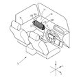
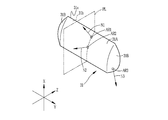
- a decorative member 10 as an example of a three-dimensional object refracts light incident on the decorative member 10 from the outside and light reflected at an interface, which will be described later, inside the decorative member 10, and changes light appearance
- the decorative member 10 has a curved shape, which will be described in detail later, and is an interior part of the automobile 11.
- the decorative member 10 is attached so as to be embedded in another interior part, and in this example, attached as a part of the dashboard 14.
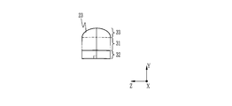
- the decorative member 10 is convex on the opposing viewer side, and is disposed on the left and right sides in FIG. 1 of the front surface portion 10A having a sectional elliptical arc shape and the front surface portion 10A in a spherical shape. And are integrally formed.
- the three-dimensional object is a decorative member that has a curved shape different from that of the decorative member 10 and is attached as a part of the steering wheel 15 or the door panel 16, for example.
- the three-dimensional object is not limited to the interior parts of a car, and may be, for example, a home appliance, a suitcase, or a toy.
- the arrow X is in the vertical direction
- the arrow Y is in the left-right direction when the windshield (window on the front side of the car, windshield, windscreen) is viewed from inside the car 11
- the arrow Z is in the forward direction.
- the decorative member 10 is provided in a state of being superimposed on the dashboard material body 21, and the dashboard material body 21 and the decorative member 10 constitute the dashboard material 22.
- the decorative member 10 is disposed so as to cover the viewer-side surface of the dashboard material body 21.
- the dashboard material body 21 is a forming member for forming the dashboard 14, has impact resistance, rigidity, heat resistance, and the like for functioning as the dashboard 14, and is formed of plastic.
- the plastic forming the dashboard material body 21 include an alloy (blend) of polycarbonate (hereinafter referred to as PC) and acrylonitrile butadiene styrene copolymer (hereinafter referred to as ABS), acrylonitrile styrene glass fiber, etc.
- acrylonitrile styrene glass fiber is an acrylonitrile styrene copolymer containing glass fiber, and it is what is called a composite material of an acrylonitrile styrene copolymer and glass fiber.
- thickness T21 of dashboard material body 21 is approximately 3 mm, it is not limited to this, and may be set appropriately according to the intended function and material as dashboard 14.
- the decorative member 10 is provided in close contact with the dashboard material body 21 in this example, the decorative member 10 may be provided with a gap.
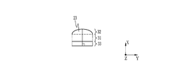
- the decorative member 10 has a plurality of convex lenses 23 on one surface. In FIG. 2, each lens 23 is drawn as a protrusion extending in the depth direction of the drawing.
- the decorative member 10 is disposed in a state where each lens 23 is on the viewer side and the opposite surface is on the dashboard material body 21 side. Therefore, the lens 23 is observed by the observer in FIG.
- the decorative member 10 is formed in a thin sheet shape, and the thickness T10 of the decorative member 10 is preferably 0.06 mm or more and 5 mm or less, and more preferably 0.1 mm or more and 0.5 mm or less. In this example, although the thickness T10 is within the above range, it varies depending on the position. However, the thickness T10 may be constant.
- the decoration member 10 is provided with the sheet
- the sheet 31 in this example is transparent, it is not limited to the transparent, and may have a property of transmitting light, that is, light transmittance.
- the light here is visible light (in a wavelength range of about 380 nm to 750 nm).
- To have light transmission includes both being transparent and having light transmission.
- transparent means that the light transmission property is extremely high, and the other side of the sheet 31 can be seen through the sheet 31.
- both sheet surfaces of the sheet 31 are illustrated as flat surfaces, but the sheet 31 has a sheet surface which is a curved surface. The details of the shape of the curved surface will be described later using another drawing.
- the sheet 31 is formed of a thermoplastic resin, and as the thermoplastic resin, polyethylene terephthalate (hereinafter referred to as PET), PC, triacetyl cellulose (hereinafter referred to as TAC), acrylic, ABS, etc. are preferable, among them , PC, and acrylic are more preferable, and in the present embodiment, they are PC.
- the sheet 31 may contain, in addition to the thermoplastic resin, a refractive index modifier, zinc oxide (ZnO), titanium oxide (TiO 2 ), or the like.
- the decorative member 10 does not have to include the sheet 31 but is preferably provided. By providing the sheet 31 and adjusting the thickness of the sheet 31, the thickness of the decorative member 10 is adjusted, so that the optical path length can be adjusted.
- the lens portion 32 is provided on one sheet surface (hereinafter, referred to as a first sheet surface) 31 a of the sheet 31 and is curved along the curved surface of the first sheet surface 31 a.
- the lens unit 32 is composed of a plurality of convex lenses 23, and each lens 23 has a columnar shape.
- the plurality of lenses 23 are arranged in parallel, that is, in a direction perpendicular to the direction in which the convex lenses 23 extend (hereinafter referred to as the extending direction) in a state where the plurality of lenses 23 are in contact with each other.
- the reference symbol ED indicates the extension direction of the lens 23
- the reference symbol LD indicates the alignment direction of the plurality of lenses 23.
- the lens unit 32 is transparent.
- the boundary is not visually recognized.
- the boundary is illustrated by a broken line for convenience of explanation.
- the boundary between the lens portion 32 and the sheet 31 is a surface connecting valleys formed by the adjacent lenses 23 in FIG.
- the lens 23 is a cylindrical lens.
- the cylindrical lens here is not limited to the case where the cross-sectional shape of a semi-circular cylinder having a strict cross-sectional shape, that is, a convex lens surface (hereinafter referred to as a first lens surface) is a circular arc, and the first lens surface Also includes lenses where the cross-sectional shape of is a parabola, an elliptic arc, or any other convex curve. In this example, the details will be described later using another drawing, but lenses 23 having mutually different cross-sectional shapes of the first lens surface are mixed.
- the lens 23 is not limited to a cylindrical lens, and may be, for example, a prism.
- the minimum value of the width W23 of the lens 23 is preferably in the range of 0.084 mm or more and 0.3 mm or less.
- the width W23 of the lens 23 is a dimension of the lens 23 in the arrangement direction LD of the plurality of lenses 23, as shown in FIG.
- the minimum value of the width W23 of the lens 23 is the smallest value among the widths of the lens 23 of the decorative member 10 when the width of the lens 23 is not constant. If the minimum value of the width W23 of the lens 23 is narrower than the above range, the amount of change in the position of the image to be viewed (the position of the image viewed through the lens 23) becomes large relative to the amount of movement of the observation point In some cases, the effect obtained by the lens 23 may be excessive.
- the designability may be degraded due to the color or pattern being mixed and the image being flickered. It will In addition, when the minimum value of the width W23 of the lens 23 is wider than the above range, the amount of change in the position of the image to be viewed becomes too small with respect to the amount of movement of the observation point. Problems may occur, such as reduced effectiveness. In addition, the convex shape of the lens 23 may be visually recognized. And in such a case, designability will fall. On the other hand, when the minimum value of the width W23 of the lens 23 is within the above range, the convex shape of the lens 23 is not visually recognized. In addition, the effect obtained by the lens 23 can be exhibited without excess or deficiency, and the design can be improved.
- the width W23 of the lens 23 is more preferably in the range of 0.127 mm or more and 0.254 mm or less. When the minimum value of the width W23 of the lens 23 is within this range, the above-described effect is more remarkable.
- the decorative member 10 is made by molding a molding material 39 (see FIGS. 12 and 13) as described later, and the lens 23 of the decoration member 10 is in a mode in which the lens of the molding material 39 is deformed. It has become.
- the modeling material 39 used has a lens pitch in the range of 80 LPI (line per inch) or more and 3000 LPI or less.
- the decorative member 10 is formed using the respective modeling materials 39 in which the lens pitch is 80 LPI, 100 LPI, 200 LPI, and 300 LPI.
- the modeling material 39 one in which lenses are arranged without gaps at the above-described pitch is used. That is, in the modeling material 39, when the lens pitch is converted into a length, this length is equal to the lens width.
- the decorative member 10 when the lens pitch P23 (see FIG. 3) is converted to a length, this length is equal to the width W23 of the lens 23.
- the decorative member 10 is formed using each of the modeling materials 39 in which the lens pitch is 80 LPI, 100 LPI, 200 LPI, and 300 LPI. In this case, the lens in a portion not deformed by molding
- the width W23 of 23 is 0.317 mm, 0.254 mm, 0.127 mm, and 0.084 mm, respectively.
- the above-mentioned range of the above-mentioned minimum value of the width W23 of the lens 23 is thus specified.
- the width W23 becomes larger as the lens 23 in a portion largely deformed in the arranging direction LD of the plurality of lenses 23 by molding.
- the stretch ratio of the most extended part in the alignment direction LD is 100%
- the most extended part in the alignment direction LD of the decorative member 10 The width W23 of the lens 23 at the point is respectively 0.634 mm, 0.508 mm, 0.254 mm, and 0.168 mm.
- the lens portion 32 includes at least one of a thermosetting polymer and a photocuring polymer.
- a thermosetting polymer is a polymer produced by heating a thermosetting compound.
- a thermosetting compound is a compound that cures upon heating.
- a photocurable polymer is a polymer produced
- the photocurable compound is a compound which is cured by irradiation with light.
- the lens portion 32 of the present embodiment includes at least one of a thermosetting polymer and a photocuring polymer, and may include both a thermosetting polymer and a photocuring polymer.
- a cured product of tricyclodecanedimethanol diacrylate hereinafter referred to as ADCP
- a curable composition of a monofunctional and / or bifunctional or more (meth) acrylate a curable composition of a compound having a vinyl group
- the sheet 31 may also contain these thermosetting polymers and / or photocuring polymers.
- the image forming unit 33 is an image display body visually recognized when the decorative member 10 is observed from the lens unit 32 side.
- the image forming portion 33 is provided in the form of a layer on the second sheet surface 31 b of the sheet 31 in a curved state along the curved surface of the second sheet surface 31 b.
- the image forming unit 33 includes a printing layer 35 on which an image 37 is formed (depicted) by printing, and a support 36 on which the printing layer 35 is provided.
- the print layer 35 is in contact with the second sheet surface 31 b.
- the image forming unit 33 provided with the printing layer 35 on the support 36 is disposed on the second sheet surface 31 b, but the present invention is not limited to this mode.
- an image forming unit formed only of the printing layer 35 may be provided on the second sheet surface 31 b.
- the image 37 may be formed by a method different from printing, such as transfer.
- materials for forming the image 37 various known materials such as paints, paints such as dyes, etc. can be used.
- the sheet 31 is formed of the above-mentioned PET, PC, and TAC, it is preferable to form a print layer 35 on the sheet 31 using a pigment.
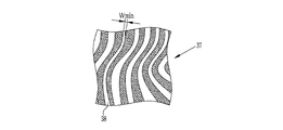
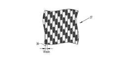
- Examples of the image 37 formed on the print layer 35 include various images such as patterns and material patterns. Moreover, as a pattern, various patterns, such as a stripe pattern, a geometric pattern, a ripple, a sand pattern, a lattice pattern, a checkered pattern, a polka-dot pattern, etc. are mentioned. Furthermore, as a material pattern, various material patterns such as carbon tone, wood grain tone, marble (marble) tone, aluminum tone with hairline processing, etc. may be mentioned. As described above, various images can be mentioned as the image 37 formed on the print layer 35, but in the following, an example in which the image 37 is a stripe pattern shown in FIG. 4 and a carbon tone shown in the image 37 An example which is
- the image 37 formed on the print layer 35 is provided with a specific image depiction area 38 in which a specific image is depicted.
- the specific image depiction area 38 differs depending on the type of the image 37 and the like, but in the present embodiment, it shows an area different from a portion where at least one of gradation and tone is adjacent. Generally, in an image, there are many regions (regions different in at least one of shades and tones from adjacent portions) in this way, but in the present embodiment, the minimum value of the width of such regions is The narrowest "Wmin" area is designated as the specific image depiction area 38.
- the width of the region is the length of the region in the direction orthogonal to the longitudinal direction when the longitudinal direction exists in the region as in the case where the region is, for example, a strip.
- alternating white and black bands bands in which the white and black stripes in FIG. 4 are composed of straight lines instead of curves.
- stripes bands in which the white and black stripes in FIG. 4 are composed of straight lines instead of curves.
- the width of the stripe length in the short side direction.
- there is a longitudinal direction in the area such as when the area is a circle arranged on the background in a polka dot pattern or a white or black square in a plaid (checkered pattern) combining black and white squares, etc.
- the distance between the two of the two parallel lines sandwiching the area is the narrowest distance, the distance between the lines is there. That is, if the area is a circle in the polka dot pattern described above, the diameter of the circle is the width of the area, and if the area is a square forming a plaid, the length of one side of the square is the width of the area Become. However, in the present embodiment, a fine line (or point) having a width of 0.06 mm or less and which is hard to be recognized (or invisible) is not regarded as an area or a part of an area. .
- the white stripe drawn area having the narrowest width minimum value Wmin is the specific image depiction area 38.
- the image 37 is configured from white and black rectangles of equal shape and size arranged on a white background. That is, in FIG. 5, the minimum value Wmin of the width is equal regardless of the color or position, regardless of the area in which any rectangle is drawn. For this reason, in FIG. 5, if it is a rectangular drawn area, it is possible to set it as a specific image drawing area regardless of the color and position of the drawn rectangle, but in the present embodiment.
- the black rectangular drawn area at the lower left in the drawing is the specific image display area 38.
- the clearance gap exists between rectangles, since the width
- an example is considered in which an area different from the area where at least one of lightness and color tone is adjacent is regarded as an area, but the area in the present invention is not limited to this, and one of the elements constituting an image when observed.
- a solid black solid rectangle is used as the black rectangle, but instead, in order to apply gradation within the range recognized as black or to simulate carbon fiber Even in the case of using hairline-like streaks, when observed, it is recognized as one rectangle as in the case of the black rectangle.
- a combination of a plurality of regions with different shades or tones may be regarded as a region.
- an area in which the minimum value of the width is the narrowest "Wmin" among such areas may be set as the specific image depiction area.
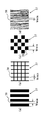
- FIG. 6 (a) shows a stripe pattern
- FIG. 6 (b) shows a lattice pattern
- FIG. 6 (c) shows a checkered pattern
- FIG. 6 (d) shows a wood grain pattern.
- the specific image depiction area 38 is provided in the image 37 formed in the printing layer 35.
- the image may be visually recognized as flickering, etc.
- the width of the specific image depiction area 38 is too wide, the effect obtained by the lens 23 (the position of the image viewed with the movement of the observation point changes) Effects such as the ability to improve the For this reason, in the decorative member 10, the minimum value Wmin of the width of the specific image depiction area 38 is in the range of 2 mm or more and 20 mm or less. By doing this, the image does not flicker and the effect of the lens 23 can be sufficiently obtained, so that the design can be improved.
- the decorative member 10 is observed from a distance of several tens of centimeters to several meters, such as interior parts of automobiles and home appliances, and the minimum value Wmin of the width of the specific image depiction area 38
- a more remarkable effect can be obtained when observing from such a distance.
- the observation angle changes by about 8 ° when the observation point shifts by 30 cm, but in the decorative member 10, observation is made in the range of 5 ° to 10 ° including this
- the minimum value Wmin of the width of the specific image depiction area 38 is determined in the above range so that the designability is improved in such a case.
- the whole size of the image 37 formed in the printing layer 35 has a horizontal width (width in the horizontal direction) of 2 m or less and a vertical width (vertical width) of 0.5 m or less.
- the minimum value Wmin of the width of the specific image depiction area 38 is determined to be in the above range so that the designability of the image of such size is further improved. Therefore, it is preferable that the entire size of the image 37 formed on the print layer 35 be 2 m or less in width and 0.5 m or less in height.
- the minimum value Wmin of the width of the specific image depiction area 38 is more preferably in the range of 4 mm or more and 8 mm or less.
- the sheet 31 has a front surface 31A which is a component of the front surface 10A (see FIG. 1) of the decorative member 10 and a side surface 31B which is a component of the side surface 10B (see FIG. 1). It is integrally formed.
- the first sheet surface 31a has three regions in which the directions of the normals are different, and one of the directions of the normals of each region is a curved surface having a slope in a plane including the other two. Specifically, it is as follows.
- Arbitrary two regions on the first sheet surface 31a of the front surface portion 31A are referred to as a first region AR1 and a second region AR2, and arbitrary regions on the first sheet surface 31a of the side surface portion 31B are referred to as a third region AR3.
- region AR2 are taken on the XZ plane, it is not restricted to this.
- the normal from the first area AR1 is the first normal N1
- the normal from the second area AR2 is the second normal N2
- the normal from the third area is the third normal N3
- a plane PL including the direction of the first normal N1 and the direction of the second normal N2 is conceived.
- the plane PL is a plane including two “directions”.
- the plane PL is the same plane as the plane including the two straight lines.
- the plane containing the two straight lines can not be thought, but the plane containing the “directions” of the two straight lines can be thought, this plane (in the twist position A plane that includes the "directions” of the two straight lines) is conceptualized as a plane PL.
- the plane PL is not defined as a plane including two straight lines, but is defined as a plane including "directions" of two straight lines, so the first normal N1 and the second normal N2 are tentatively Even in the position of twisting, the plane PL is reminiscent.
- the direction of the third normal N3 is inclined with respect to the plane PL.
- the first area AR1 and the second area AR2 may be taken from the side surface part 31B, and the third area AR3 may be taken from the front surface part 31A.
- the first area AR1 and the third area AR3 may be taken from the front surface portion 31A, and the second region AR2 may be taken from the side surface portion 31B.
- the sheet 31 having the first sheet surface 31 a and the second sheet surface 31 b is bent in the extending direction ED of the lens 23 and the arranging direction LD of the plurality of lenses 23.
- the lens part 32 (refer FIG. 3) and the image formation part 33 (refer FIG. 3) are respectively curved and provided along the above curved surfaces, the decoration member 10 (refer FIG. 3) is also,
- the extension direction ED of the lens 23 and the alignment direction LD of the plurality of lenses 23 have a curved shape.
- the decorative member 10 (image forming unit 33) has a shape that is bent in the extending direction ED of the lens 23 and the arranging direction LD of the plurality of lenses 23, so that the light is reflected.
- the image 37 of the printing layer 35 is observed as an image having nonuniformity, and is observed, for example, with color shades and / or lightness differences. For example, when the image 37 for variable vision is formed, the image to be observed is switched by the movement of the observation point, and the light appearance is changed also in the image after switching.
- the appearance of light differs for each part of the decorative member 10, and the switching timing is also different for each part, so that the image to be observed is a conventional flat lenticular sheet or prism sheet It is observed as a more varied pattern, for example, as compared to the case where the image forming layers are present and the case where they are simply rounded. As a result, the design is enhanced and the interior is rich in decoration.
- the decorative member 10 has a curved shape similar to that of the sheet 31 having the first sheet surface 31a and the second sheet surface 31b formed of the above-described curved surfaces.
- the movement direction of the observation point at which the switching from one of the images 37 for variable vision to the other is recognized is not only one in the alignment direction LD but a plurality of directions. Therefore, in addition to the initially set observation points, observation points at which switching of the image is recognized by movement appear.
- the decorative member 10 is bent in the alignment direction LD and / or the extension direction ED of the lenses 23, so that the light appearance at any one observation point is more complicated, and The movement of the observation point makes the appearance of the image recognized as light more complicated, and the design is further enhanced.
- the curvature radius of the 1st sheet surface 31a and the 2nd sheet surface 31b is 50 mm or more and 500 mm or less. Within this range, the effect of the lens 23 can be sufficiently obtained while the flickering of the image 37 of the printing layer 35 is prevented, and the design can be further improved. Moreover, it is more preferable to set the curvature radius of the 1st sheet surface 31a and the 2nd sheet surface 31b to 60 mm or more and 400 mm or less. By doing this, the above-mentioned effects become more remarkable.
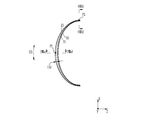
- the curvature of the sheet 31 changes along the extension direction ED of the lens 23.
- the curvature of the sheet 31 changes along the extension direction ED of any one lens 23 of the front face portion 10A.
- the curvature of the front surface portion 10A also changes along the extending direction ED of the lens 23.
- the curvature of the sheet 31 and the front surface portion 10A gradually and gradually increases as going from the center in the vertical direction X to the upper side and the lower side, respectively.
- hatching indicating a cross section is omitted in order to avoid complication of the drawing.
- the lens portion 32 of the front surface portion 10A preferably includes a plurality of lenses 23 having different cross-sectional shapes at the first position and the second position in the extending direction ED.
- the center in the vertical direction X in FIG. 8 is taken as a first position P1
- a second position P2 is taken at the upper end.
- the cross section of the first position P1 has substantially the same width of the lens 23, but the height is high and the cross section is substantially semicircular is there.
- the lens 23 at the second position P2 has a semicircular shape.
- the cross-sectional shape of the lens 23 continuously changes from the first position P1 to the second position P2.
- each cross section of the 1st position P1 and the 2nd position P2 may become reverse by the conditions in the case of manufacturing the decoration member 10 by the below-mentioned heat processing.
- the thickness T32 of the lens portion 32 (see FIG. 3) is preferably changed along the extension direction ED of the lens 23, and this is the case in this embodiment. As shown in FIG. 8, the thickness T ⁇ b> 32 of the lens portion 32 is continuously and gradually reduced from the center in the vertical direction X toward the upper side and the lower side.
- the lens portion 32 has the lens 23 in which the cross-sectional shapes of the first position P1 and the second position P2 in the extension direction ED are different, and / or the thickness T32 is an extension of the lens 23 Because it changes along the direction ED, the appearance of light becomes more complicated and the design is more surely enhanced. For example, when the observation point is at a position facing the first position P1 and the focal position at the time of observation at the observation point is on the interface between the sheet 31 and the image forming unit 33 at the first position P1. The image of the first position P1 is clearly observed in outline and / or color, but the image in the second position P2 is observed more unclearly in outline and / or color than the image of the first position P1. Ru.
- the cross-sectional shape of the lens 23 continuously changes as it goes from the first position P1 to the second position P2. For this reason, as it goes to the 2nd position P2 from the 1st position P1, the definition is changing continuously. Therefore, the curved shape of the decorative member 10 is more reliably utilized, and when observed at an arbitrary observation point, a sense of perspective (a sense of depth, a three-dimensional effect) is more surely felt.
- design feeling is enhanced by enhancing the sense of moving image or afterimage, in combination with the sense of perspective (depth feeling, three-dimensional feeling), or the change of color tone becomes complicated. Furthermore, in an environment where the amount of light is small, for example, texture can be felt even at night, designability is enhanced.
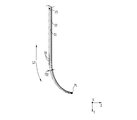
- the curvature of the sheet 31 changes along the arrangement direction LD of the plurality of lenses 23. This is also the case in this embodiment. Therefore, as shown in FIG. 10, the curvature of the decorative member 10 also changes along the arrangement direction LD of the plurality of lenses 23 as a whole.
- the decoration member 10 of this example is symmetrical about the center in the left-right direction Y, only the right half of the left-right direction Y is shown in FIG.
- the curvature of the sheet 31 and the decorative member 10 gradually and continuously increases from the center to the end in the left-right direction Y. Thereby, the appearance of light due to movement of the viewpoint is more complicated, and the designability is further enhanced.
- hatching indicating a cross section is omitted in order to avoid complication of the drawing.
- the shape of the cross section of the lens 23 at the third position in the arranging direction LD of the plurality of lenses 23 and the shape of the cross section of the lens 23 at the fourth position are different from each other. preferable.
- the center in the left-right direction Y in FIG. 10 is taken as a third position P3 and the fourth position P4 is taken at the lower end.
- the width of the lens 23 is smaller and the height is higher.
- the shape of the cross section of the lens 23 continuously changes from the third position P3 to the fourth position P4.
- the shape of each cross section of the third position P3 and the fourth position P4 may be reversed depending on the conditions in the case of manufacturing the decorative member 10 by thermoforming described later.
- the thickness T32 of the lens portion 32 (see FIG. 3) is preferably changed along the arranging direction LD of the plurality of lenses 23, and this is the case in this embodiment. As shown in FIG. 10, the thickness T ⁇ b> 32 of the lens portion 32 gradually and gradually decreases from the center to the end in the left-right direction Y.
- the lens portion 32 includes the plurality of lenses 23 having different shapes of cross sections of the third position P3 and the fourth position P4 in the alignment direction LD, and / or the thickness T32 is a plurality of Since the light changes along the arrangement direction LD of the lenses 23, as in the case of the extension direction ED described above, the appearance of light is more complicated and the designability is more surely improved.
- the decoration member 10 can be manufactured from the modeling material 39 (refer FIG. 12) made into the planar sheet
- a similar layer structure includes a light transmitting sheet (not shown), a lens portion (not shown) provided on one of the sheet surfaces of the sheet and formed of a convex lens, and the other of the sheets. And an image forming unit on which an image is formed.
- the thickness of the lens portion and the shapes of the plurality of lenses do not have to be different as in the decorative member 10, and may be uniform.
- each of the lenses may have a constant cross-sectional shape in the extending direction ED.
- the respective materials of the sheet of the modeling material 39 and the image forming unit are the same as the respective materials of the sheet 31 and the image forming unit 33.
- the lens portion contains a thermosetting compound which produces the above-mentioned thermosetting polymer by heating and / or a photocurable compound which produces the above-mentioned photocurable polymer. And a thermosetting compound and / or a photocurable compound are made into the so-called semi-hardened state which is not completely hardened.
- thermosetting compound and / or a photocurable compound for example, tricyclodecanedimethanol diacrylate (hereinafter referred to as ADCP), bisphenol A (hereinafter referred to as Bis-A), phenol resin, monofunctional and / or Or a bifunctional or higher functional (meth) acrylate, a compound having a vinyl group, and the like, and in one example of this embodiment, ADCP is used.
- ADCP tricyclodecanedimethanol diacrylate
- Bis-A bisphenol A
- phenol resin monofunctional and / or Or a bifunctional or higher functional (meth) acrylate
- a compound having a vinyl group and the like
- the manufacturing method of the decoration member 10 is demonstrated below.
- the decorative member 10 is manufactured by a molding material manufacturing process of manufacturing the molding material 39 and a molding process of molding the molding material 39 into the decoration member 10.
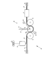
- a modeling material manufacturing apparatus 40 for manufacturing a modeling material 39 includes a delivery machine 41, a coating machine 42, a lens forming unit 45, a winding machine 46, and the like.
- the delivery machine 41 is for supplying to the lens forming unit 45 the film 51 in which the long light transmitting sheet member to be the sheet of the forming material 39 and the forming member to be the image forming portion overlap in the thickness direction. is there.
- the film 51 is wound in a roll shape, and a film roll (not shown) on which the film 51 is wound is set in a roll shape, and the film 51 is sent out from the film roll.
- the film 51 also functions as a support of the coating film 52 formed by the coating device 42.
- a driving roller (not shown) that rotates in the circumferential direction is disposed between the lens forming unit 45 and the winder 46. The film 51 is wound around the drive roller, and the film 51 is conveyed toward the downstream of the modeling material manufacturing apparatus 40 by the rotation of the drive roller.
- the coating machine 42 is for forming the coating film 52 on the film 51.
- the coating film 52 is made into the lens portion of the modeling material 39 by the lens forming unit 45.
- the coating machine 42 continuously discharges the supplied coating liquid 53.
- the coating solution 52 flows out toward the film 51 traveling in the longitudinal direction, whereby the coating film 52 is formed on one film surface of the film 51.
- the film 51 on which the coating film 52 is formed is guided to the lens forming unit 45.
- the coating liquid 53 contains at least one of a thermosetting compound and a photocurable compound.
- the thermosetting compound is included, and the thermosetting compound generates the above-mentioned thermosetting compound contained in the lens portion of the modeling material 39 by heating by the heater 57 described later.
- the coating liquid 53 since the modeling material 39 including the photocurable polymer in the lens portion is manufactured, the coating liquid 53 also contains the photocurable compound.
- the photocurable compound in the present embodiment is described as the above ADCP, it is not limited thereto, and may be any of a monomer, an oligomer, and a polymer.
- the coating liquid 53 may contain these solvents according to the thermosetting compound and photocurable compound to be used.
- the lens forming unit 45 is for forming (forming) each lens of the modeling material 39.
- the lens forming unit 45 includes a shaper 56, a heater 57, a light source 58, and the like.
- the shaping machine 56 is for forming a lens of a protrusion.
- the shaping machine 56 includes a first support roller 61, a second support roller 62, and a shape imparting roller 63 as a shape imparting member.
- the first support roller 61, the second support roller 62, and the shape imparting roller 63 are disposed in a state where the rotation axis is in the width direction of the film 51.
- the first support roller 61, the shape imparting roller 63, and the second support roller 62 are disposed in order from the upstream side.
- the first support roller 61 and the second support roller 62 are disposed on the side opposite to the coating film 52 with respect to the transport path of the film 51 in this example, and the film 51 is wound around the circumferential surface.
- the first support roller 61 and the second support roller 62 are driven to rotate as the film 51 is transported.
- the first support roller 61 and the second support roller 62 may be rotated in synchronization with the transport of the film 51 by a motor.
- the shape imparting roller 63 is provided to face the first support roller 61 and the second support roller 62, and is disposed on the side of the coating film 52 with respect to the transport path of the film 51.
- the shape imparting roller 63 cooperates with the first support roller 61 and the second support roller 62 to continuously form on the coating film 52 a lens portion having a lens surface that protrudes in a semi-cylindrical shape. That is, the first support roller 61 and the second support roller 62 function as a support member for supporting the film 51, and also function as a shape imparting member for forming a protruding lens surface.
- a plurality of concave portions 63a having a semi-cylindrical cross section are formed in order to form a lens portion.
- Each recess 63 a extends in the axial direction of the forming roller 63, that is, in the width direction of the film 51, and the plurality of recesses 63 a are formed along the circumferential direction of the forming roller 63.
- the shape imparting roller 63 is rotated by the motor 66 in a state where the film 51 is nipped between the first support roller 61 and the second support roller 62.
- the rotation direction of the shape imparting roller 63 is the direction in which the film 51 is transported (the counterclockwise direction in FIG. 12).
- the shape imparting roller 63 applies the film 51 being conveyed on the first support roller 61, the second support roller 62, and between the first support roller 61 and the second support roller 62.
- the shape of the recess 63 a is transferred to the coating film 52 to form a lens portion.
- the respective recesses 63a may extend in the circumferential direction of the forming roller, that is, in the longitudinal direction of the film 51, and the plurality of recesses 63a may be formed along the axial direction of the forming roller.
- the shape of the recess 63 a of the shape imparting roller 63 is determined according to the shape of the lens to be formed.
- a pressure regulator 67 be provided to the shape imparting roller 63 as in the present embodiment.
- the pressure regulator 67 regulates the pressing force of the shaping roller 63 against the coating film 52 when transferring the shape of the recess 63 a.
- the pressure regulator 67 more reliably forms the lens portion by adjusting the pressing force.
- the heater 57 cures the thermosetting compound in the formed lens portion, but brings it into a semi-cured state so that the thermosetting compound can be further cured in a later step.
- the heater 57 is disposed to surround the conveyance path downstream of the shaping machine 56, and supplies a heated gas such as air to the inside. By passing through the heater 57, the curing of the thermosetting compound in the lens portion formed by the shaper 56 proceeds. The presence or absence and the residual ratio of the thermosetting compound can be confirmed and quantified by comparing before curing and after curing by spectral analysis of FT-IR (Fourier transform infrared spectrometer). can do.
- FT-IR Fastier transform infrared spectrometer
- the peak intensities at 810 cm -1 and 1635 cm -1 are confirmed and quantified by comparing before curing and after curing, respectively.
- the peak at 810 cm -1 corresponds to the C—H (single bond of carbon and hydrogen) out-of-plane vibration of vinyl group
- the residual amount or the residual ratio of the thermosetting compound is adjusted by adjusting the internal temperature of the heater 57 and the time of passing through the heater 57.
- the inside temperature of the heater 57 that is, the temperature of the gas fed into the inside is preferably in the range of 100 ° C. or more and 200 ° C. or less, and is set to 160 ° C. in the present embodiment.
- the time for passing through the heater 57 that is, the time for the heat treatment is preferably in the range of 10 seconds to 200 seconds, and is 30 seconds in this embodiment.
- the modeling material 39 is obtained in a state of containing the first thermosetting compound.
- At least one of the heater 57 and various heating devices such as, for example, a radiant heater (not shown) and / or a blower (not shown) for delivering a heated gas may be used.
- various heating devices such as, for example, a radiant heater (not shown) and / or a blower (not shown) for delivering a heated gas
- the various heating devices as described above are positioned upstream of the shaping roller 63 so as to face the first support roller 61. You may provide in the position by the side of the film 51 which opposed, the position which opposes the 2nd support roller 62 in the downstream of the shape provision roller 63, etc.
- the various heating devices as described above are provided and used at any of these positions, the heater 57 provided downstream of the shaping machine 56 may not be used.
- the light source 58 is for curing the photocurable compound to produce a photocured polymer.
- the light source 58 is provided in a state of facing the shaping roller 63, and emits ultraviolet light. While passing through the film 51 while being wound around the shaping roller 63, the light from the light source 58 is applied to the coating film 52 through the film 51 to cure the photocurable compound, whereby the photocuring weight is reduced. Coalescing produces.
- the type of light emitted by the light source 58 and the output from which the light is emitted depend on the type of photocurable compound.
- a light source 58 and / or another light source may be provided.
- the other light source is a position facing the first support roller 61 at the upstream of the shaping roller 63, a position at the film 51 side facing the shaping roller 63, and a shape It can be provided at a position facing the second support roller 62 downstream of the application roller 63 or the like.
- the winder 46 winds the obtained long shaped material 39 around a winding core (not shown) to form a roll.
- the rolled forming material 39 is cut into a sheet by a cutting machine. Therefore, even if the modeling material manufacturing apparatus 40 does not use the winding machine 46, a cutting machine (not shown) for cutting the long modeling material 39 into a sheet is provided at the position of the winding machine 46. Good.
- a peeling machine (not shown) is provided between the lens forming unit 45 and the winding machine 46 to peel off the sheet portion from the lens portion. It is sufficient to peel off the part.
- the shape imparting roller 63 is used as the shape imparting member, the shape imparting member is not limited to this.
- a plate-shaped shape-providing member having a recess 63a formed on its surface may be used.
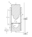
- the molding apparatus 70 shown in FIG. 13 is for molding the sheet-like modeling material 39 into the decorative member 10.
- the molding apparatus 70 includes a mold unit 72, a moving mechanism 73, a heater 74, and a control unit 76, and performs heat molding processing under heating.
- the molding method is not limited to the thermal molding, and for example, a method such as vacuum molding or vacuum pressure air molding may be used.
- the mold unit 72 has a first mold 77, a second mold 78, and a body mold 79.
- the body mold 79 has a rectangular cross-sectional shape in the direction orthogonal to the compression direction.
- the body mold 79 has a guide hole 79 a penetrating in the compression direction by the first mold 77 and the second mold 78.
- the compression direction is the vertical direction in FIG.
- the first mold 77 and the second mold 78 are guided by the inner wall of the guide hole 79a, and are movable in the compression direction.
- the first mold 77 and the second mold 78 mold the decorative member 10 by compression molding of the forming material 39 in the barrel 79.
- the modeling material 39 is formed in a shape suitable for compression molding of the decorative member 10.
- a transfer surface 77a for forming a second lens surface 11B and a first lens surface 11A having curved shapes of the decorative member 10 on opposing surfaces facing each other, 78a is formed.
- the transfer surface 77a of the first mold 77 is formed in a convex shape
- the transfer surface 78a of the second mold 78 is formed in a concave shape.
- the moving mechanism 73 moves the first mold 77 and the second mold 78 in the direction to increase or decrease the distance between them. Further, when the molding material 39 is accommodated in the barrel 79, the first mold 77 is moved upward to retract from the barrel 79.
- the heater 74 heats the mold material 72 in the body mold 79 by heating the mold unit 72.
- the moving mechanism 73 and the heater 74 are controlled by the control unit 76.
- the control unit 76 controls the amount of heat generation of the heater 74 to adjust the temperature in the body mold 79.
- the decorative member 10 described above is an example of a three-dimensional object having a curved shape projecting in one direction, but may be a three-dimensional object having a shape curved in a plurality of directions. That is, the forming material 39 can be formed into a three-dimensional object having a shape curved in a plurality of directions, and for that purpose, the mold unit 72 of the forming apparatus 70 is made of gold according to the curved shape of the object. It may be replaced by a mold unit.
- the modeling material 39 was produced by the modeling material manufacturing apparatus 40.
- the decorative member 10 was manufactured from each obtained modeling material 39 using the shaping
- the modeling material 39 mutually made the pitch of a lens mutually different, and created the decoration member 10 using each modeling material 39 which is 80 LPI, 100 LPI, 200 LPI, and 300 LPI of a lens pitch.
- the stretch ratio of the most extended portion in the alignment direction LD was 100%.
- the curvature radius of the 1st sheet surface 31a of the decoration member 10 and the 2nd sheet surface 31b was within the limits of 60 mm or more and 400 mm or less.
- the above-mentioned stripe (stripe) pattern, carbon tone, checkered pattern, and wood grain tone were used.
- the decorative member 10 was formed using the image 37 to be formed on the print layer 35 in the entire size of 2 m or less in width and 0.5 m or less in height.
- the minimum value Wmin of the width of the obtained specific image depiction area 38 was in the range of 4 mm or more and 8 mm or less for all images, such as stripe (stripe) pattern, carbon tone, checkered pattern, and wood tone.
- the decoration member 10 was manufactured similarly to the Example.
- the image used here is representatively a stripe (stripe) pattern, carbon tone, and the minimum value Wmin of the width of the specific image depiction area 38 is smaller (1 mm) and larger (30 mm) than in each example.
- the decorative member 10 was manufactured in the same manner as in the example except using.
- each decorative member 10 obtained in Examples and Comparative Examples was evaluated.
- the image 37 of the print layer 35 does not flicker and the visibility effect by the lens 23 is also sufficiently obtained. And had high designability.
- the one (1 mm) having a smaller minimum value Wmin of the width of the specific image depiction area 38 has an excessive effect obtained by the lens 23 The image flickering was noticeable and the designability was low.
- Wmin was large (30 mm)
- the change amount of the image to be recognized was small, and the designability was low.
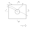
- the decorative member 90 illustrated in FIG. 14 is formed in a sheet shape, and includes a rectangular flat portion 91 and a dome-shaped curved portion 92 formed at the center of the flat portion 91.
- the flat portion 91 has a short side length L1 of 120 mm and a long side length L2 of 150 mm.
- the curved surface portion 92 is formed as a convex portion protruding upward in FIG.
- the curved surface portion 92 is hemispherical with a constant radius, and the diameter L3 is 40 mm.
- the decorative member 90 is formed by thermoforming a rectangular sheet-like shaped material 39 having a short side length of 120 mm and a long side length of 150 mm. Therefore, the decorative member 90 has the same layer structure as the decorative member 10. However, the image formed on the print layer 35 is different from the image on the decorative member 10 as described later using another drawing.
- the lens 23 (see FIG. 3) is omitted in FIG. 14 to avoid complication of the figure
- the lens portion 32 (see FIG. 3) is the upper side in FIG. 14 and the image forming portion 33 (see FIG. 3). Is located on the lower side in FIG.
- the alignment direction LD is the short side direction of the flat portion 91
- the extending direction ED is the long side direction of the flat portion 91.
- the image formed on the printing layer 35 of the decorative member 90 is composed of four types of rectangular image portions (hereinafter referred to as rectangular image portions) 95a, 95b, 95c, 95d. .
- the rectangular image portions 95a, 95b, 95c, 95d are in a square arrangement.
- the rectangular image portions 95a and the rectangular image portions 95b are alternately arranged in the extending direction ED, and similarly, the rectangular image portions 95c and the rectangular image portions 95d are alternately arranged in the extending direction ED.
- the rectangular image portions 95a and the rectangular image portions 95c are alternately arranged in the arranging direction LD, and similarly, the rectangular image portions 95b and the rectangular image portions 95d are alternately arranged in the arranging direction LD.
- the rectangular image portions 95a, 95b, 95c, and 95d are not distinguished from one another, they are described as the rectangular image portion 95.
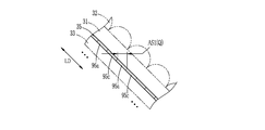
- the decorative member 90 is viewed from the lens unit 32 (see FIG. 3) side as shown in FIG. Further, in the curved surface portion 92, the point Q is taken on the straight line passing through the point P and extending in the arranging direction LD, and the point R is taken on the straight line passing through the point P and extending in the extending direction ED. .
- the point Q is an angle ⁇ with the first tangent plane TP1 (where 0 ° ⁇ ⁇ 90 It is a contact point of the second tangent plane TP2 at which the curved surface portion 92 is 45 °.
- the point R is also a contact point between the second tangential plane TP2 and the curved surface portion 92 (see FIG. 20).
- the point Q and the point R are points on the curved surface portion 92 in which the direction of the observation point is inclined 45 ° with respect to the normal.
- the first tangent plane TP1 and the second tangent plane TP2 ignore the curved surface that constitutes the first lens surface of the lens 23, and the curved surface as the entire curved surface portion 92 (A virtual curved surface connecting the apexes of the first lens surfaces of the respective lenses 23) is specified.
- the decorative member 90 is observed from 600 mm above the point P in FIG. “600 mm” is a sufficient distance that the straight line connecting the observation point and the point P and the straight line connecting the observation point to the point Q can be regarded as parallel when the point P and the point Q are viewed from one observation point It is the set distance.
- the width of the rectangular image portion 95 where the observation from the observation point can be expected is set as the expected width AS1.
- AS1 the width of the rectangular image portion 95 of the point P and the expected width AS1 of the point Q are distinguished, the former is described as AS1 (P) and the latter is described as AS1 (Q).
- AS1 the width of the rectangular image portion 95 of the point P and the expected width AS1 of the point Q are distinguished.
- the rectangular image portions 95a, 95c, 95a,... Of the point P can be considered to be aligned in the direction perpendicular to the direction of the observation point.
- the rectangular image parts 95a, 95c, 95a,... Of the point Q are 45 in the arranging direction of the rectangular image parts 95a, 95c, 95a,. It can be considered that they are aligned in an inclined direction.
- 18 and 19 illustrate the rectangular image portions 95a, 95c, 95a, and so on, but they may be rectangular image portions 95b, 95d, 95b, and so on.
- the point P and Q are observed from the observation point described above, the point P is observed from directly above (direction away from the rectangular image portion 95 vertically), and the point Q is obliquely upward (oblique from the rectangular image portion 95) It is observed from the direction away from the top). For this reason, when observing the point P, it is a point directly below the point P in the rectangular image portion 95 (a point intersecting the perpendicular from the point P in the rectangular image portion 95). The point at which the optical axis intersects with the rectangular image portion 95 is visually recognized. On the other hand, when observing the point Q, a point shifted from immediately below the point Q is observed.
- the lens portion 32 and the sheet 31 have different refractive indices from the outside (the atmosphere that fills the space in which the decorative member 90 is disposed), the lens portion 32 when observed from obliquely above like point Q. And the position observed by refraction of light by the sheet 31. Thus, the point P is observed at the point P, whereas the point deviated from the point Q is observed at the point Q (action A2).
- the point P and the point P are determined by the difference between the expected width AS1 (P) of the point P and the expected width AS1 (Q) of the point Q.
- the decorative member 90 is observed from 600 mm above the point P in FIG. "600 mm" is a sufficient distance that the straight line connecting the observation point and the point P and the straight line connecting the observation point to the point R can be regarded as parallel when the point P and the point R are viewed from one observation point It is the distance set as.
- the width of the rectangular image portion 95 where the observation from the observation point can be expected is taken as an expected width AS2.
- AS2 (P) the width of the rectangular image portion 95 of the point P
- AS2 (R) the width of the rectangular image portion 95 where the observation from the observation point can be expected
- AS2 (P) the width of the rectangular image portion 95 of the point P
- AS2 (R) the width of the rectangular image portion 95 of the point R
- the image sequence RA is drawn and described, it may be the image sequence RB.
- the combination of the above actions A1 to A3, B1 and B2 makes the light appearance of the decorative member 90 more complicated, and exhibits excellent design.
- the above-described operations are the same whether the images formed by the rectangular image portions 95a to 95d are images for variable vision and stereoscopic vision.
- the thickness of the lens portion 32 differs depending on the position, and / or the cross-sectional shape of the lens 23 varies depending on the position, in addition to the above functions A1 to A3 and B1 and B2, the thickness and Or because the depth of focus differs depending on the position due to the difference in cross-sectional shape, the appearance of light becomes more varied.
- the pitch P23 of the lenses 23 and the width of the rectangular image portion in the arrangement direction LD are smaller, the definition is improved, and the appearance of light becomes more varied.
- the width of the specific image depiction area 38 is set to prevent the flicker of the image, and the effect of the lens 23 can be sufficiently obtained. That is, as in the present invention, setting the width of the specific image depiction area 38 is effective particularly in a state of being formed into a three-dimensional shape.
- the difference in the position of the depth of focus due to the difference in the above-mentioned actions A1 to A3, B1 and B2, thickness and / or cross-sectional shape makes the appearance of light more varied while the appearance of the image is Flickering can be prevented, the effect of the lens 23 can be sufficiently obtained, and the design can be improved more effectively.
Landscapes
- Physics & Mathematics (AREA)
- Engineering & Computer Science (AREA)
- General Physics & Mathematics (AREA)
- Mechanical Engineering (AREA)
- Optics & Photonics (AREA)
- Chemical & Material Sciences (AREA)
- Combustion & Propulsion (AREA)
- Transportation (AREA)
- Geometry (AREA)
- Laminated Bodies (AREA)
- Stereoscopic And Panoramic Photography (AREA)
- Shaping Of Tube Ends By Bending Or Straightening (AREA)
Abstract
L'objectif de la présente invention est de fournir un article façonné en trois dimensions qui confère une variation de l'apparence de la lumière, et qui a des propriétés de conception améliorées. Un élément décoratif (10), qui est un article façonné en trois dimensions, est pourvu d'une feuille (31), d'une partie lentille (32) et d'une partie de formation d'image (33). La feuille (31) est transparente à la lumière et a une première surface de feuille (31a) formant une surface incurvée. La partie lentille (32) est disposée de manière à se courber le long de la première surface de feuille (31a). La partie lentille (32) est pourvue d'une pluralité de lentilles en forme de crête (23) disposées parallèlement les unes aux autres. La partie de formation d'image (33) est pourvue d'une région de représentation d'image spécifique (38) dans laquelle une image spécifique est représentée. La valeur minimale de la largeur de la région de représentation d'image spécifique (38) se situe dans une plage allant de 2 mm ou plus et 20 mm ou moins. La surface incurvée comprend une première région (AR1) à une troisième région (AR3) ayant des directions de ligne normale mutuellement différentes, et a une forme dans laquelle une direction parmi les directions de ligne normale de chaque région est inclinée par rapport à un plan comprenant les deux autres directions de ligne normale.
Priority Applications (4)
| Application Number | Priority Date | Filing Date | Title |
|---|---|---|---|
| EP19741637.3A EP3741541A4 (fr) | 2018-01-19 | 2019-01-18 | Article façonné en trois dimensions |
| CN201980009016.XA CN111629882A (zh) | 2018-01-19 | 2019-01-18 | 立体造形物 |
| JP2019566521A JPWO2019142902A1 (ja) | 2018-01-19 | 2019-01-18 | 立体造形物 |
| US16/931,343 US20200346486A1 (en) | 2018-01-19 | 2020-07-16 | Three-dimensional modeled article |
Applications Claiming Priority (2)
| Application Number | Priority Date | Filing Date | Title |
|---|---|---|---|
| JP2018007690 | 2018-01-19 | ||
| JP2018-007690 | 2018-01-19 |
Related Child Applications (1)
| Application Number | Title | Priority Date | Filing Date |
|---|---|---|---|
| US16/931,343 Continuation US20200346486A1 (en) | 2018-01-19 | 2020-07-16 | Three-dimensional modeled article |
Publications (1)
| Publication Number | Publication Date |
|---|---|
| WO2019142902A1 true WO2019142902A1 (fr) | 2019-07-25 |
Family
ID=67302301
Family Applications (1)
| Application Number | Title | Priority Date | Filing Date |
|---|---|---|---|
| PCT/JP2019/001433 WO2019142902A1 (fr) | 2018-01-19 | 2019-01-18 | Article façonné en trois dimensions |
Country Status (5)
| Country | Link |
|---|---|
| US (1) | US20200346486A1 (fr) |
| EP (1) | EP3741541A4 (fr) |
| JP (1) | JPWO2019142902A1 (fr) |
| CN (1) | CN111629882A (fr) |
| WO (1) | WO2019142902A1 (fr) |
Families Citing this family (3)
| Publication number | Priority date | Publication date | Assignee | Title |
|---|---|---|---|---|
| KR102666265B1 (ko) | 2017-11-02 | 2024-05-14 | 피씨엠에스 홀딩스, 인크. | 라이트 필드 디스플레이에서 조리개 확장을 위한 방법 및 시스템 |
| KR20210066797A (ko) * | 2018-08-29 | 2021-06-07 | 피씨엠에스 홀딩스, 인크. | 모자이크 주기적 층에 기반한 광 필드 디스플레이를 위한 광학 방법 및 시스템 |
| CN112298027B (zh) * | 2020-11-03 | 2022-05-10 | 上海延锋金桥汽车饰件系统有限公司 | 一种车辆内饰件 |
Citations (10)
| Publication number | Priority date | Publication date | Assignee | Title |
|---|---|---|---|---|
| US5642226A (en) * | 1995-01-18 | 1997-06-24 | Rosenthal; Bruce A. | Lenticular optical system |
| JPH11109287A (ja) * | 1997-10-03 | 1999-04-23 | Toppan Printing Co Ltd | レンチキュラー・ディスプレイ装置 |
| JP2004173749A (ja) * | 2002-11-25 | 2004-06-24 | Santekkusu:Kk | 遊技機 |
| JP2005131891A (ja) | 2003-10-29 | 2005-05-26 | Seven Corporation:Kk | 装飾材及び電飾装置 |
| JP2005131261A (ja) | 2003-10-31 | 2005-05-26 | Sente Creations:Kk | 三次元レンチキュラー及び三次元レンチキュラーを備えた玩具体 |
| JP2008064938A (ja) | 2006-09-06 | 2008-03-21 | Toppan Printing Co Ltd | レンズ付き印刷物 |
| JP2011154301A (ja) | 2010-01-28 | 2011-08-11 | Fujifilm Corp | プリンタ及びプリント方法 |
| WO2012144110A1 (fr) * | 2011-04-22 | 2012-10-26 | グラパックジャパン株式会社 | Feuille d'affichage d'images, et corps d'affichage d'images |
| WO2017126540A1 (fr) * | 2016-01-19 | 2017-07-27 | 富士フイルム株式会社 | Matériau de moulage, son procédé de fabrication, article mis en forme de manière tridimensionnelle, et son procédé de fabrication |
| WO2018016613A1 (fr) * | 2016-07-22 | 2018-01-25 | 富士フイルム株式会社 | Article moulé tridimensionnel |
Family Cites Families (7)
| Publication number | Priority date | Publication date | Assignee | Title |
|---|---|---|---|---|
| DE10044603A1 (de) * | 1999-09-22 | 2001-04-05 | Eastman Kodak Co | Verfahren und Vorrichtung zur Herstellung von Linsenrastermaterial |
| US6781761B2 (en) * | 2002-08-29 | 2004-08-24 | Mark A. Raymond | Lenticular lens system and method for use in producing images with clear-walled containers |
| US6984425B2 (en) * | 2002-11-19 | 2006-01-10 | Raymond Mark A | Containers with integral lenticular systems and inner label inserts |
| US7457039B2 (en) * | 2006-06-07 | 2008-11-25 | Genie Lens Technologies, Llc | Lenticular display system with a lens sheet spaced apart from a paired interlaced image |
| CN101628484A (zh) * | 2008-07-17 | 2010-01-20 | 杨德宁 | 一种生产建筑装饰光栅板材的装置及工艺方法 |
| JP5613124B2 (ja) * | 2011-08-24 | 2014-10-22 | 富士フイルム株式会社 | 加飾シート及びインモールド成形方法 |
| TWM514577U (zh) * | 2015-07-23 | 2015-12-21 | 胡聯雄 | 折射透鏡以及具有該折射透鏡之片狀結構 |
-
2019
- 2019-01-18 WO PCT/JP2019/001433 patent/WO2019142902A1/fr unknown
- 2019-01-18 CN CN201980009016.XA patent/CN111629882A/zh active Pending
- 2019-01-18 JP JP2019566521A patent/JPWO2019142902A1/ja active Pending
- 2019-01-18 EP EP19741637.3A patent/EP3741541A4/fr not_active Withdrawn
-
2020
- 2020-07-16 US US16/931,343 patent/US20200346486A1/en not_active Abandoned
Patent Citations (10)
| Publication number | Priority date | Publication date | Assignee | Title |
|---|---|---|---|---|
| US5642226A (en) * | 1995-01-18 | 1997-06-24 | Rosenthal; Bruce A. | Lenticular optical system |
| JPH11109287A (ja) * | 1997-10-03 | 1999-04-23 | Toppan Printing Co Ltd | レンチキュラー・ディスプレイ装置 |
| JP2004173749A (ja) * | 2002-11-25 | 2004-06-24 | Santekkusu:Kk | 遊技機 |
| JP2005131891A (ja) | 2003-10-29 | 2005-05-26 | Seven Corporation:Kk | 装飾材及び電飾装置 |
| JP2005131261A (ja) | 2003-10-31 | 2005-05-26 | Sente Creations:Kk | 三次元レンチキュラー及び三次元レンチキュラーを備えた玩具体 |
| JP2008064938A (ja) | 2006-09-06 | 2008-03-21 | Toppan Printing Co Ltd | レンズ付き印刷物 |
| JP2011154301A (ja) | 2010-01-28 | 2011-08-11 | Fujifilm Corp | プリンタ及びプリント方法 |
| WO2012144110A1 (fr) * | 2011-04-22 | 2012-10-26 | グラパックジャパン株式会社 | Feuille d'affichage d'images, et corps d'affichage d'images |
| WO2017126540A1 (fr) * | 2016-01-19 | 2017-07-27 | 富士フイルム株式会社 | Matériau de moulage, son procédé de fabrication, article mis en forme de manière tridimensionnelle, et son procédé de fabrication |
| WO2018016613A1 (fr) * | 2016-07-22 | 2018-01-25 | 富士フイルム株式会社 | Article moulé tridimensionnel |
Non-Patent Citations (1)
| Title |
|---|
| See also references of EP3741541A4 |
Also Published As
| Publication number | Publication date |
|---|---|
| US20200346486A1 (en) | 2020-11-05 |
| CN111629882A (zh) | 2020-09-04 |
| EP3741541A4 (fr) | 2021-04-14 |
| JPWO2019142902A1 (ja) | 2021-01-28 |
| EP3741541A1 (fr) | 2020-11-25 |
Similar Documents
| Publication | Publication Date | Title |
|---|---|---|
| WO2019142902A1 (fr) | Article façonné en trois dimensions | |
| JP6731052B2 (ja) | 立体造形物 | |
| US7731813B2 (en) | Manufacture of display devices with ultrathin lens arrays for viewing interlaced images | |
| TW200907497A (en) | Double-sided turning film | |
| US7307790B1 (en) | Ultrathin lens arrays for viewing interlaced images | |
| WO2017126540A1 (fr) | Matériau de moulage, son procédé de fabrication, article mis en forme de manière tridimensionnelle, et son procédé de fabrication | |
| US20110227238A1 (en) | Apparatus and method for producing optical sheeting | |
| KR20120115541A (ko) | 오토스테레오스코픽 디스플레이 구성요소에 부착하기 위한 미세복제된 필름 | |
| US8284491B2 (en) | Lenticular product | |
| WO2019142903A1 (fr) | Objet tridimensionnel | |
| TWI274675B (en) | Print medium with lenticular effect | |
| JP6731051B2 (ja) | 立体造形物 | |
| JP2023052177A (ja) | 合わせガラス | |
| WO2014056124A1 (fr) | Procédé d'impression 3d, panneau décoratif et boite lumineuse fabriqués au moyen dudit procédé d'impression 3d | |
| AU2020205517A1 (en) | Indicator body and labeled printed matter | |
| JP5310268B2 (ja) | 光学シート、バックライトユニット及びディスプレイ装置 | |
| JP2019510659A (ja) | 可変的可撓性のためのフィルム構造 | |
| KR102043261B1 (ko) | 이종 렌즈 필름의 제조방법 및 그에 의해 제조된 이종 렌즈 필름 | |
| WO2018062148A1 (fr) | Matériau de modélisation, modèle tridimensionnel, procédé permettant de produire un matériau de modélisation et procédé permettant de produire un modèle tridimensionnel | |
| WO2018062149A1 (fr) | Objet tridimensionnel et procédé de fabrication d'objet tridimensionnel | |
| JP2018051990A (ja) | 立体造形物の製造方法 | |
| US20220176661A1 (en) | Method for manufacturing an autostereoscopic screen and method for converting from a screen for displaying a two-dimensional image to a screen for displaying an autostereoscopic image | |
| KR20210157644A (ko) | 렌티큘러 용기 및 이의 제조방법 | |
| JP2012194397A (ja) | 光学シート、面光源装置、透過型表示装置、光学シートの製造方法 | |
| JP2004191726A (ja) | レンチキュラレンズシート及びその製造方法 |
Legal Events
| Date | Code | Title | Description |
|---|---|---|---|
| 121 | Ep: the epo has been informed by wipo that ep was designated in this application |
Ref document number: 19741637 Country of ref document: EP Kind code of ref document: A1 |
|
| ENP | Entry into the national phase |
Ref document number: 2019566521 Country of ref document: JP Kind code of ref document: A |
|
| NENP | Non-entry into the national phase |
Ref country code: DE |
|
| ENP | Entry into the national phase |
Ref document number: 2019741637 Country of ref document: EP Effective date: 20200819 |