WO2019142902A1 - 立体造形物 - Google Patents
立体造形物 Download PDFInfo
- Publication number
- WO2019142902A1 WO2019142902A1 PCT/JP2019/001433 JP2019001433W WO2019142902A1 WO 2019142902 A1 WO2019142902 A1 WO 2019142902A1 JP 2019001433 W JP2019001433 W JP 2019001433W WO 2019142902 A1 WO2019142902 A1 WO 2019142902A1
- Authority
- WO
- WIPO (PCT)
- Prior art keywords
- lens
- image
- sheet
- point
- width
- Prior art date
Links
- 239000000463 material Substances 0.000 description 64
- 150000001875 compounds Chemical class 0.000 description 33
- 239000011248 coating agent Substances 0.000 description 23
- 238000000576 coating method Methods 0.000 description 23
- 230000000694 effects Effects 0.000 description 23
- 229920001187 thermosetting polymer Polymers 0.000 description 23
- 238000005034 decoration Methods 0.000 description 21
- 238000007639 printing Methods 0.000 description 18
- 238000000465 moulding Methods 0.000 description 17
- 238000004519 manufacturing process Methods 0.000 description 14
- 239000011295 pitch Substances 0.000 description 14
- 238000007493 shaping process Methods 0.000 description 13
- 229920000642 polymer Polymers 0.000 description 11
- 238000010438 heat treatment Methods 0.000 description 10
- 230000008859 change Effects 0.000 description 9
- OKTJSMMVPCPJKN-UHFFFAOYSA-N Carbon Chemical compound [C] OKTJSMMVPCPJKN-UHFFFAOYSA-N 0.000 description 8
- 229910052799 carbon Inorganic materials 0.000 description 8
- 230000009471 action Effects 0.000 description 7
- 239000004417 polycarbonate Substances 0.000 description 7
- 238000001723 curing Methods 0.000 description 6
- 239000012778 molding material Substances 0.000 description 6
- 239000004634 thermosetting polymer Substances 0.000 description 6
- 238000004804 winding Methods 0.000 description 6
- 238000000034 method Methods 0.000 description 5
- 238000000016 photochemical curing Methods 0.000 description 5
- 239000000758 substrate Substances 0.000 description 5
- XECAHXYUAAWDEL-UHFFFAOYSA-N acrylonitrile butadiene styrene Chemical compound C=CC=C.C=CC#N.C=CC1=CC=CC=C1 XECAHXYUAAWDEL-UHFFFAOYSA-N 0.000 description 4
- 229920000122 acrylonitrile butadiene styrene Polymers 0.000 description 4
- 239000004676 acrylonitrile butadiene styrene Substances 0.000 description 4
- 229920001893 acrylonitrile styrene Polymers 0.000 description 4
- 230000005888 antibody-dependent cellular phagocytosis Effects 0.000 description 4
- 230000006835 compression Effects 0.000 description 4
- 238000007906 compression Methods 0.000 description 4
- 239000003365 glass fiber Substances 0.000 description 4
- 239000007788 liquid Substances 0.000 description 4
- 230000007246 mechanism Effects 0.000 description 4
- 239000000203 mixture Substances 0.000 description 4
- SCUZVMOVTVSBLE-UHFFFAOYSA-N prop-2-enenitrile;styrene Chemical compound C=CC#N.C=CC1=CC=CC=C1 SCUZVMOVTVSBLE-UHFFFAOYSA-N 0.000 description 4
- 229920005992 thermoplastic resin Polymers 0.000 description 4
- 239000002023 wood Substances 0.000 description 4
- 230000005540 biological transmission Effects 0.000 description 3
- 230000000052 comparative effect Effects 0.000 description 3
- 238000005520 cutting process Methods 0.000 description 3
- 239000007789 gas Substances 0.000 description 3
- 229920000139 polyethylene terephthalate Polymers 0.000 description 3
- 239000005020 polyethylene terephthalate Substances 0.000 description 3
- 238000003825 pressing Methods 0.000 description 3
- 230000032258 transport Effects 0.000 description 3
- 238000011144 upstream manufacturing Methods 0.000 description 3
- 125000000391 vinyl group Chemical group [H]C([*])=C([H])[H] 0.000 description 3
- NIXOWILDQLNWCW-UHFFFAOYSA-M Acrylate Chemical compound [O-]C(=O)C=C NIXOWILDQLNWCW-UHFFFAOYSA-M 0.000 description 2
- 238000005033 Fourier transform infrared spectroscopy Methods 0.000 description 2
- VEBCLRKUSAGCDF-UHFFFAOYSA-N ac1mi23b Chemical compound C1C2C3C(COC(=O)C=C)CCC3C1C(COC(=O)C=C)C2 VEBCLRKUSAGCDF-UHFFFAOYSA-N 0.000 description 2
- NIXOWILDQLNWCW-UHFFFAOYSA-N acrylic acid group Chemical group C(C=C)(=O)O NIXOWILDQLNWCW-UHFFFAOYSA-N 0.000 description 2
- 239000000956 alloy Substances 0.000 description 2
- 229910045601 alloy Inorganic materials 0.000 description 2
- 230000001588 bifunctional effect Effects 0.000 description 2
- 230000015572 biosynthetic process Effects 0.000 description 2
- IISBACLAFKSPIT-UHFFFAOYSA-N bisphenol A Chemical compound C=1C=C(O)C=CC=1C(C)(C)C1=CC=C(O)C=C1 IISBACLAFKSPIT-UHFFFAOYSA-N 0.000 description 2
- 238000000748 compression moulding Methods 0.000 description 2
- 230000007423 decrease Effects 0.000 description 2
- 201000003373 familial cold autoinflammatory syndrome 3 Diseases 0.000 description 2
- 230000012447 hatching Effects 0.000 description 2
- 239000004579 marble Substances 0.000 description 2
- 230000003287 optical effect Effects 0.000 description 2
- 239000003973 paint Substances 0.000 description 2
- 239000012994 photoredox catalyst Substances 0.000 description 2
- 229920003023 plastic Polymers 0.000 description 2
- 239000004033 plastic Substances 0.000 description 2
- 239000007787 solid Substances 0.000 description 2
- 238000003856 thermoforming Methods 0.000 description 2
- 238000002834 transmittance Methods 0.000 description 2
- 229920000049 Carbon (fiber) Polymers 0.000 description 1
- 229920002284 Cellulose triacetate Polymers 0.000 description 1
- UFHFLCQGNIYNRP-UHFFFAOYSA-N Hydrogen Chemical compound [H][H] UFHFLCQGNIYNRP-UHFFFAOYSA-N 0.000 description 1
- GWEVSGVZZGPLCZ-UHFFFAOYSA-N Titan oxide Chemical compound O=[Ti]=O GWEVSGVZZGPLCZ-UHFFFAOYSA-N 0.000 description 1
- 206010047571 Visual impairment Diseases 0.000 description 1
- XLOMVQKBTHCTTD-UHFFFAOYSA-N Zinc monoxide Chemical compound [Zn]=O XLOMVQKBTHCTTD-UHFFFAOYSA-N 0.000 description 1
- NNLVGZFZQQXQNW-ADJNRHBOSA-N [(2r,3r,4s,5r,6s)-4,5-diacetyloxy-3-[(2s,3r,4s,5r,6r)-3,4,5-triacetyloxy-6-(acetyloxymethyl)oxan-2-yl]oxy-6-[(2r,3r,4s,5r,6s)-4,5,6-triacetyloxy-2-(acetyloxymethyl)oxan-3-yl]oxyoxan-2-yl]methyl acetate Chemical compound O([C@@H]1O[C@@H]([C@H]([C@H](OC(C)=O)[C@H]1OC(C)=O)O[C@H]1[C@@H]([C@@H](OC(C)=O)[C@H](OC(C)=O)[C@@H](COC(C)=O)O1)OC(C)=O)COC(=O)C)[C@@H]1[C@@H](COC(C)=O)O[C@@H](OC(C)=O)[C@H](OC(C)=O)[C@H]1OC(C)=O NNLVGZFZQQXQNW-ADJNRHBOSA-N 0.000 description 1
- XAGFODPZIPBFFR-UHFFFAOYSA-N aluminium Chemical compound [Al] XAGFODPZIPBFFR-UHFFFAOYSA-N 0.000 description 1
- 229910052782 aluminium Inorganic materials 0.000 description 1
- 239000004917 carbon fiber Substances 0.000 description 1
- 239000002131 composite material Substances 0.000 description 1
- 230000007812 deficiency Effects 0.000 description 1
- 239000000975 dye Substances 0.000 description 1
- 238000005516 engineering process Methods 0.000 description 1
- 230000002708 enhancing effect Effects 0.000 description 1
- 230000001747 exhibiting effect Effects 0.000 description 1
- PCHJSUWPFVWCPO-UHFFFAOYSA-N gold Chemical compound [Au] PCHJSUWPFVWCPO-UHFFFAOYSA-N 0.000 description 1
- 239000010931 gold Substances 0.000 description 1
- 229910052737 gold Inorganic materials 0.000 description 1
- 230000020169 heat generation Effects 0.000 description 1
- 229910052739 hydrogen Inorganic materials 0.000 description 1
- 239000001257 hydrogen Substances 0.000 description 1
- 230000006872 improvement Effects 0.000 description 1
- 230000001678 irradiating effect Effects 0.000 description 1
- VNWKTOKETHGBQD-UHFFFAOYSA-N methane Chemical compound C VNWKTOKETHGBQD-UHFFFAOYSA-N 0.000 description 1
- 239000003607 modifier Substances 0.000 description 1
- 239000000178 monomer Substances 0.000 description 1
- 230000000149 penetrating effect Effects 0.000 description 1
- 239000005011 phenolic resin Substances 0.000 description 1
- 239000000049 pigment Substances 0.000 description 1
- 229920000515 polycarbonate Polymers 0.000 description 1
- -1 polyethylene terephthalate Polymers 0.000 description 1
- 230000008569 process Effects 0.000 description 1
- 239000004576 sand Substances 0.000 description 1
- 239000002904 solvent Substances 0.000 description 1
- 238000010183 spectrum analysis Methods 0.000 description 1
- 230000000007 visual effect Effects 0.000 description 1
Images


Classifications
-
- B—PERFORMING OPERATIONS; TRANSPORTING
- B44—DECORATIVE ARTS
- B44F—SPECIAL DESIGNS OR PICTURES
- B44F1/00—Designs or pictures characterised by special or unusual light effects
- B44F1/02—Designs or pictures characterised by special or unusual light effects produced by reflected light, e.g. matt surfaces, lustrous surfaces
- B44F1/04—Designs or pictures characterised by special or unusual light effects produced by reflected light, e.g. matt surfaces, lustrous surfaces after passage through surface layers, e.g. pictures with mirrors on the back
-
- G—PHYSICS
- G02—OPTICS
- G02B—OPTICAL ELEMENTS, SYSTEMS OR APPARATUS
- G02B30/00—Optical systems or apparatus for producing three-dimensional [3D] effects, e.g. stereoscopic images
- G02B30/20—Optical systems or apparatus for producing three-dimensional [3D] effects, e.g. stereoscopic images by providing first and second parallax images to an observer's left and right eyes
- G02B30/26—Optical systems or apparatus for producing three-dimensional [3D] effects, e.g. stereoscopic images by providing first and second parallax images to an observer's left and right eyes of the autostereoscopic type
- G02B30/27—Optical systems or apparatus for producing three-dimensional [3D] effects, e.g. stereoscopic images by providing first and second parallax images to an observer's left and right eyes of the autostereoscopic type involving lenticular arrays
- G02B30/29—Optical systems or apparatus for producing three-dimensional [3D] effects, e.g. stereoscopic images by providing first and second parallax images to an observer's left and right eyes of the autostereoscopic type involving lenticular arrays characterised by the geometry of the lenticular array, e.g. slanted arrays, irregular arrays or arrays of varying shape or size
-
- B—PERFORMING OPERATIONS; TRANSPORTING
- B29—WORKING OF PLASTICS; WORKING OF SUBSTANCES IN A PLASTIC STATE IN GENERAL
- B29C—SHAPING OR JOINING OF PLASTICS; SHAPING OF MATERIAL IN A PLASTIC STATE, NOT OTHERWISE PROVIDED FOR; AFTER-TREATMENT OF THE SHAPED PRODUCTS, e.g. REPAIRING
- B29C59/00—Surface shaping of articles, e.g. embossing; Apparatus therefor
- B29C59/02—Surface shaping of articles, e.g. embossing; Apparatus therefor by mechanical means, e.g. pressing
-
- B—PERFORMING OPERATIONS; TRANSPORTING
- B44—DECORATIVE ARTS
- B44F—SPECIAL DESIGNS OR PICTURES
- B44F1/00—Designs or pictures characterised by special or unusual light effects
- B44F1/08—Designs or pictures characterised by special or unusual light effects characterised by colour effects
- B44F1/10—Changing, amusing, or secret pictures
-
- B—PERFORMING OPERATIONS; TRANSPORTING
- B60—VEHICLES IN GENERAL
- B60K—ARRANGEMENT OR MOUNTING OF PROPULSION UNITS OR OF TRANSMISSIONS IN VEHICLES; ARRANGEMENT OR MOUNTING OF PLURAL DIVERSE PRIME-MOVERS IN VEHICLES; AUXILIARY DRIVES FOR VEHICLES; INSTRUMENTATION OR DASHBOARDS FOR VEHICLES; ARRANGEMENTS IN CONNECTION WITH COOLING, AIR INTAKE, GAS EXHAUST OR FUEL SUPPLY OF PROPULSION UNITS IN VEHICLES
- B60K35/00—Arrangement of adaptations of instruments
-
- B60K35/211—
-
- B—PERFORMING OPERATIONS; TRANSPORTING
- B60—VEHICLES IN GENERAL
- B60K—ARRANGEMENT OR MOUNTING OF PROPULSION UNITS OR OF TRANSMISSIONS IN VEHICLES; ARRANGEMENT OR MOUNTING OF PLURAL DIVERSE PRIME-MOVERS IN VEHICLES; AUXILIARY DRIVES FOR VEHICLES; INSTRUMENTATION OR DASHBOARDS FOR VEHICLES; ARRANGEMENTS IN CONNECTION WITH COOLING, AIR INTAKE, GAS EXHAUST OR FUEL SUPPLY OF PROPULSION UNITS IN VEHICLES
- B60K37/00—Dashboards
-
- B—PERFORMING OPERATIONS; TRANSPORTING
- B60—VEHICLES IN GENERAL
- B60Q—ARRANGEMENT OF SIGNALLING OR LIGHTING DEVICES, THE MOUNTING OR SUPPORTING THEREOF OR CIRCUITS THEREFOR, FOR VEHICLES IN GENERAL
- B60Q3/00—Arrangement of lighting devices for vehicle interiors; Lighting devices specially adapted for vehicle interiors
- B60Q3/60—Arrangement of lighting devices for vehicle interiors; Lighting devices specially adapted for vehicle interiors characterised by optical aspects
-
- G—PHYSICS
- G02—OPTICS
- G02B—OPTICAL ELEMENTS, SYSTEMS OR APPARATUS
- G02B3/00—Simple or compound lenses
-
- G—PHYSICS
- G02—OPTICS
- G02B—OPTICAL ELEMENTS, SYSTEMS OR APPARATUS
- G02B3/00—Simple or compound lenses
- G02B3/0006—Arrays
- G02B3/0037—Arrays characterized by the distribution or form of lenses
- G02B3/005—Arrays characterized by the distribution or form of lenses arranged along a single direction only, e.g. lenticular sheets
-
- G—PHYSICS
- G02—OPTICS
- G02B—OPTICAL ELEMENTS, SYSTEMS OR APPARATUS
- G02B30/00—Optical systems or apparatus for producing three-dimensional [3D] effects, e.g. stereoscopic images
- G02B30/20—Optical systems or apparatus for producing three-dimensional [3D] effects, e.g. stereoscopic images by providing first and second parallax images to an observer's left and right eyes
- G02B30/26—Optical systems or apparatus for producing three-dimensional [3D] effects, e.g. stereoscopic images by providing first and second parallax images to an observer's left and right eyes of the autostereoscopic type
- G02B30/27—Optical systems or apparatus for producing three-dimensional [3D] effects, e.g. stereoscopic images by providing first and second parallax images to an observer's left and right eyes of the autostereoscopic type involving lenticular arrays
-
- G—PHYSICS
- G03—PHOTOGRAPHY; CINEMATOGRAPHY; ANALOGOUS TECHNIQUES USING WAVES OTHER THAN OPTICAL WAVES; ELECTROGRAPHY; HOLOGRAPHY
- G03B—APPARATUS OR ARRANGEMENTS FOR TAKING PHOTOGRAPHS OR FOR PROJECTING OR VIEWING THEM; APPARATUS OR ARRANGEMENTS EMPLOYING ANALOGOUS TECHNIQUES USING WAVES OTHER THAN OPTICAL WAVES; ACCESSORIES THEREFOR
- G03B35/00—Stereoscopic photography
- G03B35/18—Stereoscopic photography by simultaneous viewing
- G03B35/24—Stereoscopic photography by simultaneous viewing using apertured or refractive resolving means on screens or between screen and eye
-
- B—PERFORMING OPERATIONS; TRANSPORTING
- B29—WORKING OF PLASTICS; WORKING OF SUBSTANCES IN A PLASTIC STATE IN GENERAL
- B29C—SHAPING OR JOINING OF PLASTICS; SHAPING OF MATERIAL IN A PLASTIC STATE, NOT OTHERWISE PROVIDED FOR; AFTER-TREATMENT OF THE SHAPED PRODUCTS, e.g. REPAIRING
- B29C59/00—Surface shaping of articles, e.g. embossing; Apparatus therefor
- B29C59/02—Surface shaping of articles, e.g. embossing; Apparatus therefor by mechanical means, e.g. pressing
- B29C59/04—Surface shaping of articles, e.g. embossing; Apparatus therefor by mechanical means, e.g. pressing using rollers or endless belts
- B29C59/046—Surface shaping of articles, e.g. embossing; Apparatus therefor by mechanical means, e.g. pressing using rollers or endless belts for layered or coated substantially flat surfaces
-
- B60K2360/60—
Definitions
- the present invention relates to a three-dimensional object.
- a decorative film is used to enhance or differentiate the design such as the interior of an automobile or the appearance of an electric appliance.
- Many decorative films are provided with a pattern on a film substrate by printing or the like, but such decorative films have limitations in their expressiveness or variety of expression.
- a technique which enables observation of a visual image stereographic image
- This is, for example, an alternate arrangement of stripe images obtained by dividing a left viewpoint image and a right viewpoint image respectively taken from the left and right two viewpoints into stripes on the back side which is the flat lens surface side of the lenticular sheet, Two adjacent stripe images are positioned on the flat lens surface of one cylindrical lens.
- the left eye and the right eye observe the stereoscopic image by observing the left viewpoint image and the right viewpoint image with parallax through the respective cylindrical lenses. can do. Also, by dividing a multi-viewpoint image consisting of N (N is 3 or more) viewpoint images into stripes, and arranging N stripe images behind one cylindrical lens, a three-dimensional image can be obtained. It is also known to further improve the feeling (see, for example, Patent Document 1). In addition, when an image for variable vision is formed, the symbol to be observed is switched by the movement of the observation point, that is, the change of the viewing angle.
- a transparent film substrate In order to further improve the three-dimensional effect and / or the decoration effect, a transparent film substrate, a lens portion comprising a fine lens group arranged at a predetermined pitch on one surface of the transparent film substrate, and the other A lens in which a paper substrate or a film substrate is laminated via a thermoplastic resin layer on the print image side of a sheet layer provided with a print image formed such that the lens pitch and the print image pitch coincide with each other on the surface.
- An attached printed matter has been proposed (see, for example, Patent Document 2).
- the above-mentioned sheet layer has a concavo-convex structure, and the exposed surface of the above-mentioned paper base or film base is flat.
- lenticular sheets in a three-dimensional shape
- a decorative material is proposed that is molded into a three-dimensional shape in which the whole lenticular sheet is convex on one side and the opposite side is hollow (for example, see Patent Document 3).
- the decorative material is used in an electric decoration device by stacking two sheets so that the directions in which the cylindrical lenses extend are orthogonal to each other, and the hollow body is provided with a light emitter.
- a three-dimensional lenticular has been proposed in which a lenticular sheet having a print layer formed on the back surface is formed into the same shape as that of a part of the toy body, and the molded lenticular sheet is attached to the surface of a part of the toy body (See, for example, Patent Document 4).
- the printing layer in the three-dimensional lenticular is formed by dividing different patterns at equal intervals and alternately printing the divided patterns in correspondence with lenses.
- JP 2011-154301 A JP, 2008-064938, A JP 2005-131891 JP, 2005-131261, A
- the printed matter with a lens described in the technology using a lenticular sheet known in Patent Document 1 and the like and Patent Document 2 has limited application and design because of the planarity of the sheet.
- the decorative material of Patent Document 3 is provided with a cavity, and the light emitter is disposed on the side of the cavity, thereby exhibiting the decorative property, and the application is similarly limited.
- the three-dimensional lenticule used in the toy body described in Patent Document 4 is limited in its use because it is inferior in definition, and in order to extend the use, improvement in design is required.
- an object of the present invention is to provide a three-dimensional object excellent in design by giving a change to the appearance of light.
- the present invention includes a sheet, a lens unit, and an image forming unit.
- the sheet has a curved sheet surface and is light transmissive.
- the lens portion is provided on one of the sheet surfaces of the sheet so as to be curved along the curved surface, and a plurality of convex lenses are arranged in parallel.
- the image forming unit is provided on the other sheet surface of the sheet, and an image is formed.
- the curved surface has three regions in which the directions of normals are different, and one of the directions of the normals of each region is shaped so as to be inclined to a plane including the other two.
- the image forming unit is provided with a specific image depiction area in which a specific image is depicted. The minimum value of the width of the specific image depiction area is in the range of 2 mm or more and 20 mm or less.
- the minimum value of the width of the specific image depiction area is preferably in the range of 4 mm or more and 8 mm or less.
- the minimum value of the width of the lens is in the range of 0.084 mm or more and 0.3 mm or less.
- the minimum value of the width of the lens is in the range of 0.127 mm or more and 0.254 mm or less.
- the radius of curvature of the curved surface is preferably 50 mm or more and 500 mm or less.
- the curvature radius of a curved surface is 60 mm or more and 400 mm or less.
- the three-dimensional object of the present invention is changed by the appearance of light and is excellent in design.
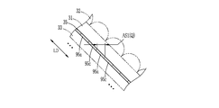
- FIG. 17 is an explanatory view of a curved surface portion of a cross section along line XVII-XVII in FIG. 16; It is explanatory drawing of the image in point P.
- FIG. 17 is an explanatory view of a curved surface portion of a cross section along line XVII-XVII in FIG. 16; It is explanatory drawing of the image in point P.
- FIG. 17 is an explanatory view of a curved surface section taken along the line XX-XX in FIG. 16; It is explanatory drawing of the image in point P.
- FIG. It is explanatory drawing of the image in point R.
- FIG. 17 is an explanatory view of a curved surface section taken along the line XX-XX in FIG. 16; It is explanatory drawing of the image in point P.
- FIG. It is explanatory drawing of the image in point R.
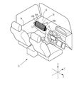
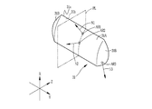
- a decorative member 10 as an example of a three-dimensional object refracts light incident on the decorative member 10 from the outside and light reflected at an interface, which will be described later, inside the decorative member 10, and changes light appearance
- the decorative member 10 has a curved shape, which will be described in detail later, and is an interior part of the automobile 11.
- the decorative member 10 is attached so as to be embedded in another interior part, and in this example, attached as a part of the dashboard 14.
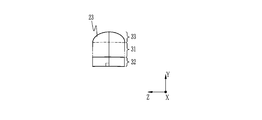
- the decorative member 10 is convex on the opposing viewer side, and is disposed on the left and right sides in FIG. 1 of the front surface portion 10A having a sectional elliptical arc shape and the front surface portion 10A in a spherical shape. And are integrally formed.
- the three-dimensional object is a decorative member that has a curved shape different from that of the decorative member 10 and is attached as a part of the steering wheel 15 or the door panel 16, for example.
- the three-dimensional object is not limited to the interior parts of a car, and may be, for example, a home appliance, a suitcase, or a toy.
- the arrow X is in the vertical direction
- the arrow Y is in the left-right direction when the windshield (window on the front side of the car, windshield, windscreen) is viewed from inside the car 11
- the arrow Z is in the forward direction.
- the decorative member 10 is provided in a state of being superimposed on the dashboard material body 21, and the dashboard material body 21 and the decorative member 10 constitute the dashboard material 22.
- the decorative member 10 is disposed so as to cover the viewer-side surface of the dashboard material body 21.
- the dashboard material body 21 is a forming member for forming the dashboard 14, has impact resistance, rigidity, heat resistance, and the like for functioning as the dashboard 14, and is formed of plastic.
- the plastic forming the dashboard material body 21 include an alloy (blend) of polycarbonate (hereinafter referred to as PC) and acrylonitrile butadiene styrene copolymer (hereinafter referred to as ABS), acrylonitrile styrene glass fiber, etc.
- acrylonitrile styrene glass fiber is an acrylonitrile styrene copolymer containing glass fiber, and it is what is called a composite material of an acrylonitrile styrene copolymer and glass fiber.
- thickness T21 of dashboard material body 21 is approximately 3 mm, it is not limited to this, and may be set appropriately according to the intended function and material as dashboard 14.
- the decorative member 10 is provided in close contact with the dashboard material body 21 in this example, the decorative member 10 may be provided with a gap.
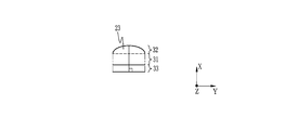
- the decorative member 10 has a plurality of convex lenses 23 on one surface. In FIG. 2, each lens 23 is drawn as a protrusion extending in the depth direction of the drawing.
- the decorative member 10 is disposed in a state where each lens 23 is on the viewer side and the opposite surface is on the dashboard material body 21 side. Therefore, the lens 23 is observed by the observer in FIG.
- the decorative member 10 is formed in a thin sheet shape, and the thickness T10 of the decorative member 10 is preferably 0.06 mm or more and 5 mm or less, and more preferably 0.1 mm or more and 0.5 mm or less. In this example, although the thickness T10 is within the above range, it varies depending on the position. However, the thickness T10 may be constant.
- the decoration member 10 is provided with the sheet
- the sheet 31 in this example is transparent, it is not limited to the transparent, and may have a property of transmitting light, that is, light transmittance.
- the light here is visible light (in a wavelength range of about 380 nm to 750 nm).
- To have light transmission includes both being transparent and having light transmission.
- transparent means that the light transmission property is extremely high, and the other side of the sheet 31 can be seen through the sheet 31.
- both sheet surfaces of the sheet 31 are illustrated as flat surfaces, but the sheet 31 has a sheet surface which is a curved surface. The details of the shape of the curved surface will be described later using another drawing.
- the sheet 31 is formed of a thermoplastic resin, and as the thermoplastic resin, polyethylene terephthalate (hereinafter referred to as PET), PC, triacetyl cellulose (hereinafter referred to as TAC), acrylic, ABS, etc. are preferable, among them , PC, and acrylic are more preferable, and in the present embodiment, they are PC.
- the sheet 31 may contain, in addition to the thermoplastic resin, a refractive index modifier, zinc oxide (ZnO), titanium oxide (TiO 2 ), or the like.
- the decorative member 10 does not have to include the sheet 31 but is preferably provided. By providing the sheet 31 and adjusting the thickness of the sheet 31, the thickness of the decorative member 10 is adjusted, so that the optical path length can be adjusted.
- the lens portion 32 is provided on one sheet surface (hereinafter, referred to as a first sheet surface) 31 a of the sheet 31 and is curved along the curved surface of the first sheet surface 31 a.
- the lens unit 32 is composed of a plurality of convex lenses 23, and each lens 23 has a columnar shape.
- the plurality of lenses 23 are arranged in parallel, that is, in a direction perpendicular to the direction in which the convex lenses 23 extend (hereinafter referred to as the extending direction) in a state where the plurality of lenses 23 are in contact with each other.
- the reference symbol ED indicates the extension direction of the lens 23
- the reference symbol LD indicates the alignment direction of the plurality of lenses 23.
- the lens unit 32 is transparent.
- the boundary is not visually recognized.
- the boundary is illustrated by a broken line for convenience of explanation.
- the boundary between the lens portion 32 and the sheet 31 is a surface connecting valleys formed by the adjacent lenses 23 in FIG.
- the lens 23 is a cylindrical lens.
- the cylindrical lens here is not limited to the case where the cross-sectional shape of a semi-circular cylinder having a strict cross-sectional shape, that is, a convex lens surface (hereinafter referred to as a first lens surface) is a circular arc, and the first lens surface Also includes lenses where the cross-sectional shape of is a parabola, an elliptic arc, or any other convex curve. In this example, the details will be described later using another drawing, but lenses 23 having mutually different cross-sectional shapes of the first lens surface are mixed.
- the lens 23 is not limited to a cylindrical lens, and may be, for example, a prism.
- the minimum value of the width W23 of the lens 23 is preferably in the range of 0.084 mm or more and 0.3 mm or less.
- the width W23 of the lens 23 is a dimension of the lens 23 in the arrangement direction LD of the plurality of lenses 23, as shown in FIG.
- the minimum value of the width W23 of the lens 23 is the smallest value among the widths of the lens 23 of the decorative member 10 when the width of the lens 23 is not constant. If the minimum value of the width W23 of the lens 23 is narrower than the above range, the amount of change in the position of the image to be viewed (the position of the image viewed through the lens 23) becomes large relative to the amount of movement of the observation point In some cases, the effect obtained by the lens 23 may be excessive.
- the designability may be degraded due to the color or pattern being mixed and the image being flickered. It will In addition, when the minimum value of the width W23 of the lens 23 is wider than the above range, the amount of change in the position of the image to be viewed becomes too small with respect to the amount of movement of the observation point. Problems may occur, such as reduced effectiveness. In addition, the convex shape of the lens 23 may be visually recognized. And in such a case, designability will fall. On the other hand, when the minimum value of the width W23 of the lens 23 is within the above range, the convex shape of the lens 23 is not visually recognized. In addition, the effect obtained by the lens 23 can be exhibited without excess or deficiency, and the design can be improved.
- the width W23 of the lens 23 is more preferably in the range of 0.127 mm or more and 0.254 mm or less. When the minimum value of the width W23 of the lens 23 is within this range, the above-described effect is more remarkable.
- the decorative member 10 is made by molding a molding material 39 (see FIGS. 12 and 13) as described later, and the lens 23 of the decoration member 10 is in a mode in which the lens of the molding material 39 is deformed. It has become.
- the modeling material 39 used has a lens pitch in the range of 80 LPI (line per inch) or more and 3000 LPI or less.
- the decorative member 10 is formed using the respective modeling materials 39 in which the lens pitch is 80 LPI, 100 LPI, 200 LPI, and 300 LPI.
- the modeling material 39 one in which lenses are arranged without gaps at the above-described pitch is used. That is, in the modeling material 39, when the lens pitch is converted into a length, this length is equal to the lens width.
- the decorative member 10 when the lens pitch P23 (see FIG. 3) is converted to a length, this length is equal to the width W23 of the lens 23.
- the decorative member 10 is formed using each of the modeling materials 39 in which the lens pitch is 80 LPI, 100 LPI, 200 LPI, and 300 LPI. In this case, the lens in a portion not deformed by molding
- the width W23 of 23 is 0.317 mm, 0.254 mm, 0.127 mm, and 0.084 mm, respectively.
- the above-mentioned range of the above-mentioned minimum value of the width W23 of the lens 23 is thus specified.
- the width W23 becomes larger as the lens 23 in a portion largely deformed in the arranging direction LD of the plurality of lenses 23 by molding.
- the stretch ratio of the most extended part in the alignment direction LD is 100%
- the most extended part in the alignment direction LD of the decorative member 10 The width W23 of the lens 23 at the point is respectively 0.634 mm, 0.508 mm, 0.254 mm, and 0.168 mm.
- the lens portion 32 includes at least one of a thermosetting polymer and a photocuring polymer.
- a thermosetting polymer is a polymer produced by heating a thermosetting compound.
- a thermosetting compound is a compound that cures upon heating.
- a photocurable polymer is a polymer produced
- the photocurable compound is a compound which is cured by irradiation with light.
- the lens portion 32 of the present embodiment includes at least one of a thermosetting polymer and a photocuring polymer, and may include both a thermosetting polymer and a photocuring polymer.
- a cured product of tricyclodecanedimethanol diacrylate hereinafter referred to as ADCP
- a curable composition of a monofunctional and / or bifunctional or more (meth) acrylate a curable composition of a compound having a vinyl group
- the sheet 31 may also contain these thermosetting polymers and / or photocuring polymers.
- the image forming unit 33 is an image display body visually recognized when the decorative member 10 is observed from the lens unit 32 side.
- the image forming portion 33 is provided in the form of a layer on the second sheet surface 31 b of the sheet 31 in a curved state along the curved surface of the second sheet surface 31 b.
- the image forming unit 33 includes a printing layer 35 on which an image 37 is formed (depicted) by printing, and a support 36 on which the printing layer 35 is provided.
- the print layer 35 is in contact with the second sheet surface 31 b.
- the image forming unit 33 provided with the printing layer 35 on the support 36 is disposed on the second sheet surface 31 b, but the present invention is not limited to this mode.
- an image forming unit formed only of the printing layer 35 may be provided on the second sheet surface 31 b.
- the image 37 may be formed by a method different from printing, such as transfer.
- materials for forming the image 37 various known materials such as paints, paints such as dyes, etc. can be used.
- the sheet 31 is formed of the above-mentioned PET, PC, and TAC, it is preferable to form a print layer 35 on the sheet 31 using a pigment.
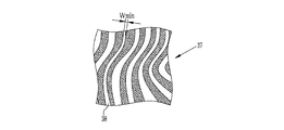
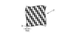
- Examples of the image 37 formed on the print layer 35 include various images such as patterns and material patterns. Moreover, as a pattern, various patterns, such as a stripe pattern, a geometric pattern, a ripple, a sand pattern, a lattice pattern, a checkered pattern, a polka-dot pattern, etc. are mentioned. Furthermore, as a material pattern, various material patterns such as carbon tone, wood grain tone, marble (marble) tone, aluminum tone with hairline processing, etc. may be mentioned. As described above, various images can be mentioned as the image 37 formed on the print layer 35, but in the following, an example in which the image 37 is a stripe pattern shown in FIG. 4 and a carbon tone shown in the image 37 An example which is
- the image 37 formed on the print layer 35 is provided with a specific image depiction area 38 in which a specific image is depicted.
- the specific image depiction area 38 differs depending on the type of the image 37 and the like, but in the present embodiment, it shows an area different from a portion where at least one of gradation and tone is adjacent. Generally, in an image, there are many regions (regions different in at least one of shades and tones from adjacent portions) in this way, but in the present embodiment, the minimum value of the width of such regions is The narrowest "Wmin" area is designated as the specific image depiction area 38.
- the width of the region is the length of the region in the direction orthogonal to the longitudinal direction when the longitudinal direction exists in the region as in the case where the region is, for example, a strip.
- alternating white and black bands bands in which the white and black stripes in FIG. 4 are composed of straight lines instead of curves.
- stripes bands in which the white and black stripes in FIG. 4 are composed of straight lines instead of curves.
- the width of the stripe length in the short side direction.
- there is a longitudinal direction in the area such as when the area is a circle arranged on the background in a polka dot pattern or a white or black square in a plaid (checkered pattern) combining black and white squares, etc.
- the distance between the two of the two parallel lines sandwiching the area is the narrowest distance, the distance between the lines is there. That is, if the area is a circle in the polka dot pattern described above, the diameter of the circle is the width of the area, and if the area is a square forming a plaid, the length of one side of the square is the width of the area Become. However, in the present embodiment, a fine line (or point) having a width of 0.06 mm or less and which is hard to be recognized (or invisible) is not regarded as an area or a part of an area. .
- the white stripe drawn area having the narrowest width minimum value Wmin is the specific image depiction area 38.
- the image 37 is configured from white and black rectangles of equal shape and size arranged on a white background. That is, in FIG. 5, the minimum value Wmin of the width is equal regardless of the color or position, regardless of the area in which any rectangle is drawn. For this reason, in FIG. 5, if it is a rectangular drawn area, it is possible to set it as a specific image drawing area regardless of the color and position of the drawn rectangle, but in the present embodiment.
- the black rectangular drawn area at the lower left in the drawing is the specific image display area 38.
- the clearance gap exists between rectangles, since the width
- an example is considered in which an area different from the area where at least one of lightness and color tone is adjacent is regarded as an area, but the area in the present invention is not limited to this, and one of the elements constituting an image when observed.
- a solid black solid rectangle is used as the black rectangle, but instead, in order to apply gradation within the range recognized as black or to simulate carbon fiber Even in the case of using hairline-like streaks, when observed, it is recognized as one rectangle as in the case of the black rectangle.
- a combination of a plurality of regions with different shades or tones may be regarded as a region.
- an area in which the minimum value of the width is the narrowest "Wmin" among such areas may be set as the specific image depiction area.
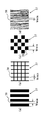
- FIG. 6 (a) shows a stripe pattern
- FIG. 6 (b) shows a lattice pattern
- FIG. 6 (c) shows a checkered pattern
- FIG. 6 (d) shows a wood grain pattern.
- the specific image depiction area 38 is provided in the image 37 formed in the printing layer 35.
- the image may be visually recognized as flickering, etc.
- the width of the specific image depiction area 38 is too wide, the effect obtained by the lens 23 (the position of the image viewed with the movement of the observation point changes) Effects such as the ability to improve the For this reason, in the decorative member 10, the minimum value Wmin of the width of the specific image depiction area 38 is in the range of 2 mm or more and 20 mm or less. By doing this, the image does not flicker and the effect of the lens 23 can be sufficiently obtained, so that the design can be improved.
- the decorative member 10 is observed from a distance of several tens of centimeters to several meters, such as interior parts of automobiles and home appliances, and the minimum value Wmin of the width of the specific image depiction area 38
- a more remarkable effect can be obtained when observing from such a distance.
- the observation angle changes by about 8 ° when the observation point shifts by 30 cm, but in the decorative member 10, observation is made in the range of 5 ° to 10 ° including this
- the minimum value Wmin of the width of the specific image depiction area 38 is determined in the above range so that the designability is improved in such a case.
- the whole size of the image 37 formed in the printing layer 35 has a horizontal width (width in the horizontal direction) of 2 m or less and a vertical width (vertical width) of 0.5 m or less.
- the minimum value Wmin of the width of the specific image depiction area 38 is determined to be in the above range so that the designability of the image of such size is further improved. Therefore, it is preferable that the entire size of the image 37 formed on the print layer 35 be 2 m or less in width and 0.5 m or less in height.
- the minimum value Wmin of the width of the specific image depiction area 38 is more preferably in the range of 4 mm or more and 8 mm or less.
- the sheet 31 has a front surface 31A which is a component of the front surface 10A (see FIG. 1) of the decorative member 10 and a side surface 31B which is a component of the side surface 10B (see FIG. 1). It is integrally formed.
- the first sheet surface 31a has three regions in which the directions of the normals are different, and one of the directions of the normals of each region is a curved surface having a slope in a plane including the other two. Specifically, it is as follows.
- Arbitrary two regions on the first sheet surface 31a of the front surface portion 31A are referred to as a first region AR1 and a second region AR2, and arbitrary regions on the first sheet surface 31a of the side surface portion 31B are referred to as a third region AR3.
- region AR2 are taken on the XZ plane, it is not restricted to this.
- the normal from the first area AR1 is the first normal N1
- the normal from the second area AR2 is the second normal N2
- the normal from the third area is the third normal N3
- a plane PL including the direction of the first normal N1 and the direction of the second normal N2 is conceived.
- the plane PL is a plane including two “directions”.
- the plane PL is the same plane as the plane including the two straight lines.
- the plane containing the two straight lines can not be thought, but the plane containing the “directions” of the two straight lines can be thought, this plane (in the twist position A plane that includes the "directions” of the two straight lines) is conceptualized as a plane PL.
- the plane PL is not defined as a plane including two straight lines, but is defined as a plane including "directions" of two straight lines, so the first normal N1 and the second normal N2 are tentatively Even in the position of twisting, the plane PL is reminiscent.
- the direction of the third normal N3 is inclined with respect to the plane PL.
- the first area AR1 and the second area AR2 may be taken from the side surface part 31B, and the third area AR3 may be taken from the front surface part 31A.
- the first area AR1 and the third area AR3 may be taken from the front surface portion 31A, and the second region AR2 may be taken from the side surface portion 31B.
- the sheet 31 having the first sheet surface 31 a and the second sheet surface 31 b is bent in the extending direction ED of the lens 23 and the arranging direction LD of the plurality of lenses 23.
- the lens part 32 (refer FIG. 3) and the image formation part 33 (refer FIG. 3) are respectively curved and provided along the above curved surfaces, the decoration member 10 (refer FIG. 3) is also,
- the extension direction ED of the lens 23 and the alignment direction LD of the plurality of lenses 23 have a curved shape.
- the decorative member 10 (image forming unit 33) has a shape that is bent in the extending direction ED of the lens 23 and the arranging direction LD of the plurality of lenses 23, so that the light is reflected.
- the image 37 of the printing layer 35 is observed as an image having nonuniformity, and is observed, for example, with color shades and / or lightness differences. For example, when the image 37 for variable vision is formed, the image to be observed is switched by the movement of the observation point, and the light appearance is changed also in the image after switching.
- the appearance of light differs for each part of the decorative member 10, and the switching timing is also different for each part, so that the image to be observed is a conventional flat lenticular sheet or prism sheet It is observed as a more varied pattern, for example, as compared to the case where the image forming layers are present and the case where they are simply rounded. As a result, the design is enhanced and the interior is rich in decoration.
- the decorative member 10 has a curved shape similar to that of the sheet 31 having the first sheet surface 31a and the second sheet surface 31b formed of the above-described curved surfaces.
- the movement direction of the observation point at which the switching from one of the images 37 for variable vision to the other is recognized is not only one in the alignment direction LD but a plurality of directions. Therefore, in addition to the initially set observation points, observation points at which switching of the image is recognized by movement appear.
- the decorative member 10 is bent in the alignment direction LD and / or the extension direction ED of the lenses 23, so that the light appearance at any one observation point is more complicated, and The movement of the observation point makes the appearance of the image recognized as light more complicated, and the design is further enhanced.
- the curvature radius of the 1st sheet surface 31a and the 2nd sheet surface 31b is 50 mm or more and 500 mm or less. Within this range, the effect of the lens 23 can be sufficiently obtained while the flickering of the image 37 of the printing layer 35 is prevented, and the design can be further improved. Moreover, it is more preferable to set the curvature radius of the 1st sheet surface 31a and the 2nd sheet surface 31b to 60 mm or more and 400 mm or less. By doing this, the above-mentioned effects become more remarkable.
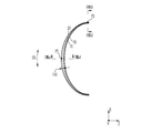
- the curvature of the sheet 31 changes along the extension direction ED of the lens 23.
- the curvature of the sheet 31 changes along the extension direction ED of any one lens 23 of the front face portion 10A.
- the curvature of the front surface portion 10A also changes along the extending direction ED of the lens 23.
- the curvature of the sheet 31 and the front surface portion 10A gradually and gradually increases as going from the center in the vertical direction X to the upper side and the lower side, respectively.
- hatching indicating a cross section is omitted in order to avoid complication of the drawing.
- the lens portion 32 of the front surface portion 10A preferably includes a plurality of lenses 23 having different cross-sectional shapes at the first position and the second position in the extending direction ED.
- the center in the vertical direction X in FIG. 8 is taken as a first position P1
- a second position P2 is taken at the upper end.
- the cross section of the first position P1 has substantially the same width of the lens 23, but the height is high and the cross section is substantially semicircular is there.
- the lens 23 at the second position P2 has a semicircular shape.
- the cross-sectional shape of the lens 23 continuously changes from the first position P1 to the second position P2.
- each cross section of the 1st position P1 and the 2nd position P2 may become reverse by the conditions in the case of manufacturing the decoration member 10 by the below-mentioned heat processing.
- the thickness T32 of the lens portion 32 (see FIG. 3) is preferably changed along the extension direction ED of the lens 23, and this is the case in this embodiment. As shown in FIG. 8, the thickness T ⁇ b> 32 of the lens portion 32 is continuously and gradually reduced from the center in the vertical direction X toward the upper side and the lower side.
- the lens portion 32 has the lens 23 in which the cross-sectional shapes of the first position P1 and the second position P2 in the extension direction ED are different, and / or the thickness T32 is an extension of the lens 23 Because it changes along the direction ED, the appearance of light becomes more complicated and the design is more surely enhanced. For example, when the observation point is at a position facing the first position P1 and the focal position at the time of observation at the observation point is on the interface between the sheet 31 and the image forming unit 33 at the first position P1. The image of the first position P1 is clearly observed in outline and / or color, but the image in the second position P2 is observed more unclearly in outline and / or color than the image of the first position P1. Ru.
- the cross-sectional shape of the lens 23 continuously changes as it goes from the first position P1 to the second position P2. For this reason, as it goes to the 2nd position P2 from the 1st position P1, the definition is changing continuously. Therefore, the curved shape of the decorative member 10 is more reliably utilized, and when observed at an arbitrary observation point, a sense of perspective (a sense of depth, a three-dimensional effect) is more surely felt.
- design feeling is enhanced by enhancing the sense of moving image or afterimage, in combination with the sense of perspective (depth feeling, three-dimensional feeling), or the change of color tone becomes complicated. Furthermore, in an environment where the amount of light is small, for example, texture can be felt even at night, designability is enhanced.
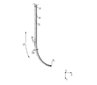
- the curvature of the sheet 31 changes along the arrangement direction LD of the plurality of lenses 23. This is also the case in this embodiment. Therefore, as shown in FIG. 10, the curvature of the decorative member 10 also changes along the arrangement direction LD of the plurality of lenses 23 as a whole.
- the decoration member 10 of this example is symmetrical about the center in the left-right direction Y, only the right half of the left-right direction Y is shown in FIG.
- the curvature of the sheet 31 and the decorative member 10 gradually and continuously increases from the center to the end in the left-right direction Y. Thereby, the appearance of light due to movement of the viewpoint is more complicated, and the designability is further enhanced.
- hatching indicating a cross section is omitted in order to avoid complication of the drawing.
- the shape of the cross section of the lens 23 at the third position in the arranging direction LD of the plurality of lenses 23 and the shape of the cross section of the lens 23 at the fourth position are different from each other. preferable.
- the center in the left-right direction Y in FIG. 10 is taken as a third position P3 and the fourth position P4 is taken at the lower end.
- the width of the lens 23 is smaller and the height is higher.
- the shape of the cross section of the lens 23 continuously changes from the third position P3 to the fourth position P4.
- the shape of each cross section of the third position P3 and the fourth position P4 may be reversed depending on the conditions in the case of manufacturing the decorative member 10 by thermoforming described later.
- the thickness T32 of the lens portion 32 (see FIG. 3) is preferably changed along the arranging direction LD of the plurality of lenses 23, and this is the case in this embodiment. As shown in FIG. 10, the thickness T ⁇ b> 32 of the lens portion 32 gradually and gradually decreases from the center to the end in the left-right direction Y.
- the lens portion 32 includes the plurality of lenses 23 having different shapes of cross sections of the third position P3 and the fourth position P4 in the alignment direction LD, and / or the thickness T32 is a plurality of Since the light changes along the arrangement direction LD of the lenses 23, as in the case of the extension direction ED described above, the appearance of light is more complicated and the designability is more surely improved.
- the decoration member 10 can be manufactured from the modeling material 39 (refer FIG. 12) made into the planar sheet
- a similar layer structure includes a light transmitting sheet (not shown), a lens portion (not shown) provided on one of the sheet surfaces of the sheet and formed of a convex lens, and the other of the sheets. And an image forming unit on which an image is formed.
- the thickness of the lens portion and the shapes of the plurality of lenses do not have to be different as in the decorative member 10, and may be uniform.
- each of the lenses may have a constant cross-sectional shape in the extending direction ED.
- the respective materials of the sheet of the modeling material 39 and the image forming unit are the same as the respective materials of the sheet 31 and the image forming unit 33.
- the lens portion contains a thermosetting compound which produces the above-mentioned thermosetting polymer by heating and / or a photocurable compound which produces the above-mentioned photocurable polymer. And a thermosetting compound and / or a photocurable compound are made into the so-called semi-hardened state which is not completely hardened.
- thermosetting compound and / or a photocurable compound for example, tricyclodecanedimethanol diacrylate (hereinafter referred to as ADCP), bisphenol A (hereinafter referred to as Bis-A), phenol resin, monofunctional and / or Or a bifunctional or higher functional (meth) acrylate, a compound having a vinyl group, and the like, and in one example of this embodiment, ADCP is used.
- ADCP tricyclodecanedimethanol diacrylate
- Bis-A bisphenol A
- phenol resin monofunctional and / or Or a bifunctional or higher functional (meth) acrylate
- a compound having a vinyl group and the like
- the manufacturing method of the decoration member 10 is demonstrated below.
- the decorative member 10 is manufactured by a molding material manufacturing process of manufacturing the molding material 39 and a molding process of molding the molding material 39 into the decoration member 10.
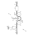
- a modeling material manufacturing apparatus 40 for manufacturing a modeling material 39 includes a delivery machine 41, a coating machine 42, a lens forming unit 45, a winding machine 46, and the like.
- the delivery machine 41 is for supplying to the lens forming unit 45 the film 51 in which the long light transmitting sheet member to be the sheet of the forming material 39 and the forming member to be the image forming portion overlap in the thickness direction. is there.
- the film 51 is wound in a roll shape, and a film roll (not shown) on which the film 51 is wound is set in a roll shape, and the film 51 is sent out from the film roll.
- the film 51 also functions as a support of the coating film 52 formed by the coating device 42.
- a driving roller (not shown) that rotates in the circumferential direction is disposed between the lens forming unit 45 and the winder 46. The film 51 is wound around the drive roller, and the film 51 is conveyed toward the downstream of the modeling material manufacturing apparatus 40 by the rotation of the drive roller.
- the coating machine 42 is for forming the coating film 52 on the film 51.
- the coating film 52 is made into the lens portion of the modeling material 39 by the lens forming unit 45.
- the coating machine 42 continuously discharges the supplied coating liquid 53.
- the coating solution 52 flows out toward the film 51 traveling in the longitudinal direction, whereby the coating film 52 is formed on one film surface of the film 51.
- the film 51 on which the coating film 52 is formed is guided to the lens forming unit 45.
- the coating liquid 53 contains at least one of a thermosetting compound and a photocurable compound.
- the thermosetting compound is included, and the thermosetting compound generates the above-mentioned thermosetting compound contained in the lens portion of the modeling material 39 by heating by the heater 57 described later.
- the coating liquid 53 since the modeling material 39 including the photocurable polymer in the lens portion is manufactured, the coating liquid 53 also contains the photocurable compound.
- the photocurable compound in the present embodiment is described as the above ADCP, it is not limited thereto, and may be any of a monomer, an oligomer, and a polymer.
- the coating liquid 53 may contain these solvents according to the thermosetting compound and photocurable compound to be used.
- the lens forming unit 45 is for forming (forming) each lens of the modeling material 39.
- the lens forming unit 45 includes a shaper 56, a heater 57, a light source 58, and the like.
- the shaping machine 56 is for forming a lens of a protrusion.
- the shaping machine 56 includes a first support roller 61, a second support roller 62, and a shape imparting roller 63 as a shape imparting member.
- the first support roller 61, the second support roller 62, and the shape imparting roller 63 are disposed in a state where the rotation axis is in the width direction of the film 51.
- the first support roller 61, the shape imparting roller 63, and the second support roller 62 are disposed in order from the upstream side.
- the first support roller 61 and the second support roller 62 are disposed on the side opposite to the coating film 52 with respect to the transport path of the film 51 in this example, and the film 51 is wound around the circumferential surface.
- the first support roller 61 and the second support roller 62 are driven to rotate as the film 51 is transported.
- the first support roller 61 and the second support roller 62 may be rotated in synchronization with the transport of the film 51 by a motor.
- the shape imparting roller 63 is provided to face the first support roller 61 and the second support roller 62, and is disposed on the side of the coating film 52 with respect to the transport path of the film 51.
- the shape imparting roller 63 cooperates with the first support roller 61 and the second support roller 62 to continuously form on the coating film 52 a lens portion having a lens surface that protrudes in a semi-cylindrical shape. That is, the first support roller 61 and the second support roller 62 function as a support member for supporting the film 51, and also function as a shape imparting member for forming a protruding lens surface.
- a plurality of concave portions 63a having a semi-cylindrical cross section are formed in order to form a lens portion.
- Each recess 63 a extends in the axial direction of the forming roller 63, that is, in the width direction of the film 51, and the plurality of recesses 63 a are formed along the circumferential direction of the forming roller 63.
- the shape imparting roller 63 is rotated by the motor 66 in a state where the film 51 is nipped between the first support roller 61 and the second support roller 62.
- the rotation direction of the shape imparting roller 63 is the direction in which the film 51 is transported (the counterclockwise direction in FIG. 12).
- the shape imparting roller 63 applies the film 51 being conveyed on the first support roller 61, the second support roller 62, and between the first support roller 61 and the second support roller 62.
- the shape of the recess 63 a is transferred to the coating film 52 to form a lens portion.
- the respective recesses 63a may extend in the circumferential direction of the forming roller, that is, in the longitudinal direction of the film 51, and the plurality of recesses 63a may be formed along the axial direction of the forming roller.
- the shape of the recess 63 a of the shape imparting roller 63 is determined according to the shape of the lens to be formed.
- a pressure regulator 67 be provided to the shape imparting roller 63 as in the present embodiment.
- the pressure regulator 67 regulates the pressing force of the shaping roller 63 against the coating film 52 when transferring the shape of the recess 63 a.
- the pressure regulator 67 more reliably forms the lens portion by adjusting the pressing force.
- the heater 57 cures the thermosetting compound in the formed lens portion, but brings it into a semi-cured state so that the thermosetting compound can be further cured in a later step.
- the heater 57 is disposed to surround the conveyance path downstream of the shaping machine 56, and supplies a heated gas such as air to the inside. By passing through the heater 57, the curing of the thermosetting compound in the lens portion formed by the shaper 56 proceeds. The presence or absence and the residual ratio of the thermosetting compound can be confirmed and quantified by comparing before curing and after curing by spectral analysis of FT-IR (Fourier transform infrared spectrometer). can do.
- FT-IR Fastier transform infrared spectrometer
- the peak intensities at 810 cm -1 and 1635 cm -1 are confirmed and quantified by comparing before curing and after curing, respectively.
- the peak at 810 cm -1 corresponds to the C—H (single bond of carbon and hydrogen) out-of-plane vibration of vinyl group
- the residual amount or the residual ratio of the thermosetting compound is adjusted by adjusting the internal temperature of the heater 57 and the time of passing through the heater 57.
- the inside temperature of the heater 57 that is, the temperature of the gas fed into the inside is preferably in the range of 100 ° C. or more and 200 ° C. or less, and is set to 160 ° C. in the present embodiment.
- the time for passing through the heater 57 that is, the time for the heat treatment is preferably in the range of 10 seconds to 200 seconds, and is 30 seconds in this embodiment.
- the modeling material 39 is obtained in a state of containing the first thermosetting compound.
- At least one of the heater 57 and various heating devices such as, for example, a radiant heater (not shown) and / or a blower (not shown) for delivering a heated gas may be used.
- various heating devices such as, for example, a radiant heater (not shown) and / or a blower (not shown) for delivering a heated gas
- the various heating devices as described above are positioned upstream of the shaping roller 63 so as to face the first support roller 61. You may provide in the position by the side of the film 51 which opposed, the position which opposes the 2nd support roller 62 in the downstream of the shape provision roller 63, etc.
- the various heating devices as described above are provided and used at any of these positions, the heater 57 provided downstream of the shaping machine 56 may not be used.
- the light source 58 is for curing the photocurable compound to produce a photocured polymer.
- the light source 58 is provided in a state of facing the shaping roller 63, and emits ultraviolet light. While passing through the film 51 while being wound around the shaping roller 63, the light from the light source 58 is applied to the coating film 52 through the film 51 to cure the photocurable compound, whereby the photocuring weight is reduced. Coalescing produces.
- the type of light emitted by the light source 58 and the output from which the light is emitted depend on the type of photocurable compound.
- a light source 58 and / or another light source may be provided.
- the other light source is a position facing the first support roller 61 at the upstream of the shaping roller 63, a position at the film 51 side facing the shaping roller 63, and a shape It can be provided at a position facing the second support roller 62 downstream of the application roller 63 or the like.
- the winder 46 winds the obtained long shaped material 39 around a winding core (not shown) to form a roll.
- the rolled forming material 39 is cut into a sheet by a cutting machine. Therefore, even if the modeling material manufacturing apparatus 40 does not use the winding machine 46, a cutting machine (not shown) for cutting the long modeling material 39 into a sheet is provided at the position of the winding machine 46. Good.
- a peeling machine (not shown) is provided between the lens forming unit 45 and the winding machine 46 to peel off the sheet portion from the lens portion. It is sufficient to peel off the part.
- the shape imparting roller 63 is used as the shape imparting member, the shape imparting member is not limited to this.
- a plate-shaped shape-providing member having a recess 63a formed on its surface may be used.
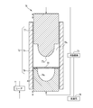
- the molding apparatus 70 shown in FIG. 13 is for molding the sheet-like modeling material 39 into the decorative member 10.
- the molding apparatus 70 includes a mold unit 72, a moving mechanism 73, a heater 74, and a control unit 76, and performs heat molding processing under heating.
- the molding method is not limited to the thermal molding, and for example, a method such as vacuum molding or vacuum pressure air molding may be used.
- the mold unit 72 has a first mold 77, a second mold 78, and a body mold 79.
- the body mold 79 has a rectangular cross-sectional shape in the direction orthogonal to the compression direction.
- the body mold 79 has a guide hole 79 a penetrating in the compression direction by the first mold 77 and the second mold 78.
- the compression direction is the vertical direction in FIG.
- the first mold 77 and the second mold 78 are guided by the inner wall of the guide hole 79a, and are movable in the compression direction.
- the first mold 77 and the second mold 78 mold the decorative member 10 by compression molding of the forming material 39 in the barrel 79.
- the modeling material 39 is formed in a shape suitable for compression molding of the decorative member 10.
- a transfer surface 77a for forming a second lens surface 11B and a first lens surface 11A having curved shapes of the decorative member 10 on opposing surfaces facing each other, 78a is formed.
- the transfer surface 77a of the first mold 77 is formed in a convex shape
- the transfer surface 78a of the second mold 78 is formed in a concave shape.
- the moving mechanism 73 moves the first mold 77 and the second mold 78 in the direction to increase or decrease the distance between them. Further, when the molding material 39 is accommodated in the barrel 79, the first mold 77 is moved upward to retract from the barrel 79.
- the heater 74 heats the mold material 72 in the body mold 79 by heating the mold unit 72.
- the moving mechanism 73 and the heater 74 are controlled by the control unit 76.
- the control unit 76 controls the amount of heat generation of the heater 74 to adjust the temperature in the body mold 79.
- the decorative member 10 described above is an example of a three-dimensional object having a curved shape projecting in one direction, but may be a three-dimensional object having a shape curved in a plurality of directions. That is, the forming material 39 can be formed into a three-dimensional object having a shape curved in a plurality of directions, and for that purpose, the mold unit 72 of the forming apparatus 70 is made of gold according to the curved shape of the object. It may be replaced by a mold unit.
- the modeling material 39 was produced by the modeling material manufacturing apparatus 40.
- the decorative member 10 was manufactured from each obtained modeling material 39 using the shaping
- the modeling material 39 mutually made the pitch of a lens mutually different, and created the decoration member 10 using each modeling material 39 which is 80 LPI, 100 LPI, 200 LPI, and 300 LPI of a lens pitch.
- the stretch ratio of the most extended portion in the alignment direction LD was 100%.
- the curvature radius of the 1st sheet surface 31a of the decoration member 10 and the 2nd sheet surface 31b was within the limits of 60 mm or more and 400 mm or less.
- the above-mentioned stripe (stripe) pattern, carbon tone, checkered pattern, and wood grain tone were used.
- the decorative member 10 was formed using the image 37 to be formed on the print layer 35 in the entire size of 2 m or less in width and 0.5 m or less in height.
- the minimum value Wmin of the width of the obtained specific image depiction area 38 was in the range of 4 mm or more and 8 mm or less for all images, such as stripe (stripe) pattern, carbon tone, checkered pattern, and wood tone.
- the decoration member 10 was manufactured similarly to the Example.
- the image used here is representatively a stripe (stripe) pattern, carbon tone, and the minimum value Wmin of the width of the specific image depiction area 38 is smaller (1 mm) and larger (30 mm) than in each example.
- the decorative member 10 was manufactured in the same manner as in the example except using.
- each decorative member 10 obtained in Examples and Comparative Examples was evaluated.
- the image 37 of the print layer 35 does not flicker and the visibility effect by the lens 23 is also sufficiently obtained. And had high designability.
- the one (1 mm) having a smaller minimum value Wmin of the width of the specific image depiction area 38 has an excessive effect obtained by the lens 23 The image flickering was noticeable and the designability was low.
- Wmin was large (30 mm)
- the change amount of the image to be recognized was small, and the designability was low.
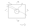
- the decorative member 90 illustrated in FIG. 14 is formed in a sheet shape, and includes a rectangular flat portion 91 and a dome-shaped curved portion 92 formed at the center of the flat portion 91.
- the flat portion 91 has a short side length L1 of 120 mm and a long side length L2 of 150 mm.
- the curved surface portion 92 is formed as a convex portion protruding upward in FIG.
- the curved surface portion 92 is hemispherical with a constant radius, and the diameter L3 is 40 mm.
- the decorative member 90 is formed by thermoforming a rectangular sheet-like shaped material 39 having a short side length of 120 mm and a long side length of 150 mm. Therefore, the decorative member 90 has the same layer structure as the decorative member 10. However, the image formed on the print layer 35 is different from the image on the decorative member 10 as described later using another drawing.
- the lens 23 (see FIG. 3) is omitted in FIG. 14 to avoid complication of the figure
- the lens portion 32 (see FIG. 3) is the upper side in FIG. 14 and the image forming portion 33 (see FIG. 3). Is located on the lower side in FIG.
- the alignment direction LD is the short side direction of the flat portion 91
- the extending direction ED is the long side direction of the flat portion 91.
- the image formed on the printing layer 35 of the decorative member 90 is composed of four types of rectangular image portions (hereinafter referred to as rectangular image portions) 95a, 95b, 95c, 95d. .
- the rectangular image portions 95a, 95b, 95c, 95d are in a square arrangement.
- the rectangular image portions 95a and the rectangular image portions 95b are alternately arranged in the extending direction ED, and similarly, the rectangular image portions 95c and the rectangular image portions 95d are alternately arranged in the extending direction ED.
- the rectangular image portions 95a and the rectangular image portions 95c are alternately arranged in the arranging direction LD, and similarly, the rectangular image portions 95b and the rectangular image portions 95d are alternately arranged in the arranging direction LD.
- the rectangular image portions 95a, 95b, 95c, and 95d are not distinguished from one another, they are described as the rectangular image portion 95.
- the decorative member 90 is viewed from the lens unit 32 (see FIG. 3) side as shown in FIG. Further, in the curved surface portion 92, the point Q is taken on the straight line passing through the point P and extending in the arranging direction LD, and the point R is taken on the straight line passing through the point P and extending in the extending direction ED. .
- the point Q is an angle ⁇ with the first tangent plane TP1 (where 0 ° ⁇ ⁇ 90 It is a contact point of the second tangent plane TP2 at which the curved surface portion 92 is 45 °.
- the point R is also a contact point between the second tangential plane TP2 and the curved surface portion 92 (see FIG. 20).
- the point Q and the point R are points on the curved surface portion 92 in which the direction of the observation point is inclined 45 ° with respect to the normal.
- the first tangent plane TP1 and the second tangent plane TP2 ignore the curved surface that constitutes the first lens surface of the lens 23, and the curved surface as the entire curved surface portion 92 (A virtual curved surface connecting the apexes of the first lens surfaces of the respective lenses 23) is specified.
- the decorative member 90 is observed from 600 mm above the point P in FIG. “600 mm” is a sufficient distance that the straight line connecting the observation point and the point P and the straight line connecting the observation point to the point Q can be regarded as parallel when the point P and the point Q are viewed from one observation point It is the set distance.
- the width of the rectangular image portion 95 where the observation from the observation point can be expected is set as the expected width AS1.
- AS1 the width of the rectangular image portion 95 of the point P and the expected width AS1 of the point Q are distinguished, the former is described as AS1 (P) and the latter is described as AS1 (Q).
- AS1 the width of the rectangular image portion 95 of the point P and the expected width AS1 of the point Q are distinguished.
- the rectangular image portions 95a, 95c, 95a,... Of the point P can be considered to be aligned in the direction perpendicular to the direction of the observation point.
- the rectangular image parts 95a, 95c, 95a,... Of the point Q are 45 in the arranging direction of the rectangular image parts 95a, 95c, 95a,. It can be considered that they are aligned in an inclined direction.
- 18 and 19 illustrate the rectangular image portions 95a, 95c, 95a, and so on, but they may be rectangular image portions 95b, 95d, 95b, and so on.
- the point P and Q are observed from the observation point described above, the point P is observed from directly above (direction away from the rectangular image portion 95 vertically), and the point Q is obliquely upward (oblique from the rectangular image portion 95) It is observed from the direction away from the top). For this reason, when observing the point P, it is a point directly below the point P in the rectangular image portion 95 (a point intersecting the perpendicular from the point P in the rectangular image portion 95). The point at which the optical axis intersects with the rectangular image portion 95 is visually recognized. On the other hand, when observing the point Q, a point shifted from immediately below the point Q is observed.
- the lens portion 32 and the sheet 31 have different refractive indices from the outside (the atmosphere that fills the space in which the decorative member 90 is disposed), the lens portion 32 when observed from obliquely above like point Q. And the position observed by refraction of light by the sheet 31. Thus, the point P is observed at the point P, whereas the point deviated from the point Q is observed at the point Q (action A2).
- the point P and the point P are determined by the difference between the expected width AS1 (P) of the point P and the expected width AS1 (Q) of the point Q.
- the decorative member 90 is observed from 600 mm above the point P in FIG. "600 mm" is a sufficient distance that the straight line connecting the observation point and the point P and the straight line connecting the observation point to the point R can be regarded as parallel when the point P and the point R are viewed from one observation point It is the distance set as.
- the width of the rectangular image portion 95 where the observation from the observation point can be expected is taken as an expected width AS2.
- AS2 (P) the width of the rectangular image portion 95 of the point P
- AS2 (R) the width of the rectangular image portion 95 where the observation from the observation point can be expected
- AS2 (P) the width of the rectangular image portion 95 of the point P
- AS2 (R) the width of the rectangular image portion 95 of the point R
- the image sequence RA is drawn and described, it may be the image sequence RB.
- the combination of the above actions A1 to A3, B1 and B2 makes the light appearance of the decorative member 90 more complicated, and exhibits excellent design.
- the above-described operations are the same whether the images formed by the rectangular image portions 95a to 95d are images for variable vision and stereoscopic vision.
- the thickness of the lens portion 32 differs depending on the position, and / or the cross-sectional shape of the lens 23 varies depending on the position, in addition to the above functions A1 to A3 and B1 and B2, the thickness and Or because the depth of focus differs depending on the position due to the difference in cross-sectional shape, the appearance of light becomes more varied.
- the pitch P23 of the lenses 23 and the width of the rectangular image portion in the arrangement direction LD are smaller, the definition is improved, and the appearance of light becomes more varied.
- the width of the specific image depiction area 38 is set to prevent the flicker of the image, and the effect of the lens 23 can be sufficiently obtained. That is, as in the present invention, setting the width of the specific image depiction area 38 is effective particularly in a state of being formed into a three-dimensional shape.
- the difference in the position of the depth of focus due to the difference in the above-mentioned actions A1 to A3, B1 and B2, thickness and / or cross-sectional shape makes the appearance of light more varied while the appearance of the image is Flickering can be prevented, the effect of the lens 23 can be sufficiently obtained, and the design can be improved more effectively.
Abstract
光の見え方に変化を与え、意匠性により優れた立体造形物を提供する。 立体造形物である装飾部材(10)は、シート(31)とレンズ部(32)と画像形成部(33)とを備える。シート(31)は、光透過性を有し、曲面とされた第1シート面(31a)を有する。レンズ部(32)は、第1シート面(31a)に沿って湾曲して設けられる。レンズ部(32)は、並列に配された突条の複数のレンズ(23)を備える。画像形成部(33)は、特定の画像が描写された特定画像描写領域(38)を備える。特定画像描写領域(38)の幅の最小値は、2mm以上、20mm以下の範囲内である。上記曲面は、法線の方向が異なる第1領域(AR1)~第3領域(AR3)を有し、各領域の法線の方向のうち1つが他の2つを含む平面に傾きをもつ形状である。
Description
本発明は、立体造形物に関する。
自動車の内装または電化製品の外観などの意匠性を高めたり差別化するためのものとして、加飾フィルムがある。加飾フィルムとしてはフィルム基材に図柄を印刷などにより施したものが多いが、こうした加飾フィルムは、表現力または表現の多様性などに限界がある。
表現力の向上または表現の多様性を図るために、半円柱状のいわゆるシリンドリカルレンズをその延在方向と直交する方向に多数並べたレンチキュラシートを用い、可変視用の画像(チェンジング画像)または立体視用の画像(立体画像)を観察できるようにした技術が知られている。これは、レンチキュラシートの平坦なレンズ面側である背面側に、例えば左右の2視点から撮影した左視点画像及び右視点画像をそれぞれストライプ状に分割したストライプ画像を交互に配置したものであり、1個のシリンドリカルレンズの平坦なレンズ面に、隣接する2つのストライプ画像を位置させたものである。立体視用の画像が形成されている場合には、左眼と右眼とが、各シリンドリカルレンズを介して、視差のある左視点画像及び右視点画像をそれぞれ観察することで、立体画像を観察することができる。また、N(Nは3以上)個の視点画像からなる多視点画像をストライプ状に分割し、1個のシリンドリカルレンズの背後に、N個のストライプ画像を並べた状態に配置することによって、立体感をさらに向上させることも知られている(例えば特許文献1参照)。また、可変視用の画像が形成されている場合には、観察点の移動、すなわち視認角度の変化によって、観察される図柄が切り替わる。
立体感及び/または加飾効果をさらに向上させるものとして、透明フィルム基材と、この透明フィルム基材の一方の面に所定のピッチで配列された微細なレンズ群からなるレンズ部と、他方の面にレンズピッチと印刷画像ピッチとが一致するように形成された印刷画像とを備えたシート層の印刷画像面側に、熱可塑性樹脂層を介して紙基材またはフィルム基材を積層したレンズ付き印刷物が提案されている(例えば、特許文献2参照)。このレンズ付き印刷物は、上記のシート層が凹凸構造をもち、かつ、上記の紙基材またはフィルム基材の露呈した表面は平坦とされている。
レンチキュラシートは立体形状とされたものがあり、例えば、レンチキュラシートを全体として片側に凸で反対側が空洞となる立体形状に成型された装飾材が提案されている(例えば、特許文献3参照)。この装飾材は、シリンドリカルレンズが延びた方向が互いに直交するように2枚重ねられ、上記空洞側に発光体が備えられることにより、電飾装置に利用される。また、印刷層が裏面に形成されたレンチキュラシートを玩具体の一部の形状と同一形状に成形し、成形したレンチキュラシートを玩具体の一部の表面に貼り付けた三次元レンチキュラが提案されている(例えば、特許文献4参照)。この三次元レンチキュラにおける上記印刷層は、異なる絵柄をそれぞれ等間隔に分割し、分割した絵柄をレンズに対応させた状態に交互に印刷することにより形成されている。
しかしながら、特許文献1などで知られるレンチキュラシートを用いた技術及び特許文献2に記載されるレンズ付き印刷物は、シートという平面性ゆえに用途及び意匠性は限られている。また、特許文献3の装飾材は、空洞を備え、かつ、その空洞側に発光体が配されることにより、その加飾性を発揮するものであり、同様に、用途は限られる。特許文献4に記載される玩具体に用いる三次元レンチキュラは、精細さに劣ることから用途に限界があり、用途を広げるには意匠性の向上が求められる。
そこで、本発明は、光の見え方に変化を与えて意匠性により優れた立体造形物を提供することを目的とする。
本発明は、シートと、レンズ部と、画像形成部とを備える。シートは、曲面とされたシート面を有し、光透過性をもつ。レンズ部は、シートの一方のシート面に、上記曲面に沿って湾曲して設けられ、突条の複数のレンズが並列に配されている。画像形成部は、シートの他方のシート面に設けられ、画像が形成されている。上記曲面は、法線の方向が異なる3つの領域を有し、各領域の法線の方向のうち1つが他の2つを含む平面に傾きをもつ形状である。画像形成部には、特定の画像が描写された特定画像描写領域が設けられている。特定画像描写領域の幅の最小値は、2mm以上、20mm以下の範囲内である。
特定画像描写領域の幅の最小値が、4mm以上、8mm以下の範囲内であることが好ましい。
レンズの幅の最小値が、0.084mm以上、0.3mm以下の範囲内であることが好ましい。
レンズの幅の最小値が、0.127mm以上、0.254mm以下の範囲内であることが好ましい。
曲面の曲率半径が、50mm以上、500mm以下であることが好ましい。
曲面の曲率半径が、60mm以上、400mm以下であることが好ましい。
本発明の立体造形物は、光の見え方により変化を与え、意匠性に優れる。
図1において、立体造形物の一例としての装飾部材10は、外部から装飾部材10に入射する光と装飾部材10の内部の後述する界面において反射した光とを屈折させ、光の見え方に変化を与えるためのものである。装飾部材10は、詳細は後述するが湾曲した形状をもち、自動車11の内装品とされている。装飾部材10は、他の内装品に埋め込むように取り付けられており、この例では、ダッシュボード14の一部として取り付けてある。装飾部材10は、対向する観察者側に凸とされ、断面楕円弧状にされた前面部10Aと、前面部10Aの図1における左右の各側方に配され、球面状にされた側面部10Bとが一体に形成されたものである。立体造形物の他の例としては、装飾部材10と異なる湾曲形状をもち、ステアリングホイール15、ドアパネル16の例えば一部として取り付ける装飾部材が挙げられる。また、立体造形物は、自動車の内装品に限られず、例えば、家電、スーツケース、玩具などでもよい。なお、図1において、矢線Xは鉛直方向、矢線Yは自動車11内からフロントガラス(自動車の前方側の窓、windshield,windscreen)を見たときにおける左右方向、矢線Zは前方向をそれぞれ意味する。
装飾部材10は、図2に示すように、ダッシュボード材本体21に重ねた状態で備えられており、ダッシュボード材本体21と装飾部材10とがダッシュボード材22を構成している。装飾部材10はダッシュボード材本体21の観察者側表面を覆うように配されている。ダッシュボード材本体21は、ダッシュボード14を形成するための形成部材であり、ダッシュボード14として機能するための耐衝撃性と剛性と耐熱性などを有し、プラスチックから形成されている。ダッシュボード材本体21を形成するプラスチックとしては、例えば、ポリカーボネート(以下、PCと称する)とアクリロニトリルブタジエンスチレン共重合体(以下、ABSと称する)とのアロイ(ブレンド)、アクリロニトリル・スチレン・グラスファイバなど公知の種々のものを用いることができ、本実施形態では、PCとABSとのアロイ(ブレンド)としてある。なお、上記のアクリロニトリル・スチレン・グラスファイバとは、グラスファイバを含有するアクリロニトリルスチレン共重合体であり、アクリロニトリルスチレン共重合体とグラスファイバとのいわゆる複合材料である。この例では、ダッシュボード材本体21の厚みT21は概ね3mmとしてあるが、これに限定されず、ダッシュボード14としての目的とする機能と素材とに応じて適宜設定してよい。
装飾部材10は、この例では、ダッシュボード材本体21と密着した状態に設けられているが、隙間をもって設けられてもよい。装飾部材10は、一方の表面に突条の複数のレンズ23を有する。図2においては、各レンズ23は、突条が紙面奥行方向に延びているものとして描いてある。装飾部材10は、各レンズ23が観察者側に、反対側の面がダッシュボード材本体21側に向いた状態で配される。したがって、図1において観察者からはレンズ23が観察される。装飾部材10は薄いシート状に形成されており、装飾部材10の厚みT10は0.06mm以上5mm以下であることが好ましく、0.1mm以上0.5mm以下であることがより好ましい。この例では、厚みT10は上記範囲内であるものの、位置によって異なる。ただし、厚みT10は一定でもよい。
装飾部材10は、図3に示すように、シート31とレンズ部32と画像形成部33とを備える。この例でのシート31は、透明としてあるが、透明に限られず、光が透過する性質、すなわち光透過性を有すればよい。ここでの光は、可視光(波長範囲が概ね380nm以上750nm以下の領域)である。光透過性を有するとは、透明であることと、透光性を有することとの両方を含む。透明とは、光が通過する性質において、透過率が極めて高く、シート31を通してシート31の向こう側が透けて見える状態の性質を意味する。透光性を有するとは、光が透過する性質を有しているが、透過する光が拡散されるため、または透過率が低いために、「透明」と違って、シート31を通してシート31の向こう側の形状等を明確に認識できない、または全く認識できない状態の性質である。図3においては、説明の便宜上、シート31の両シート面を平面に描いているが、このシート31は曲面とされたシート面を有する。なお、曲面の形状の詳細は、別の図面を用いて後述する。
シート31は、熱可塑性樹脂から形成されており、熱可塑性樹脂としては、ポリエチレンテレフタレート(以下、PETと称する)、PC、トリアセチルセルロース(以下、TACと称する)、アクリル、ABSなどが好ましく、中でも、PC、アクリルがより好ましく、本実施形態ではPCとしている。また、シート31は、上記熱可塑性樹脂に加えて、屈折率調整剤、酸化亜鉛(ZnO)、酸化チタン(TiO2)等を含んでいてもよい。
装飾部材10はシート31を備える必要はないが、備える方が好ましい。シート31を設け、このシート31の厚みを調節することにより、装飾部材10の厚みが調節されるので光路長を調節することができる。
レンズ部32は、シート31の一方のシート面(以下、第1シート面と称する)31aに設けられており、第1シート面31aの曲面に沿って湾曲している。レンズ部32は、前述のように突条の複数のレンズ23から構成されており、各レンズ23は柱状である。これら複数のレンズ23は互いに接した状態で、突条のレンズ23が延びた方向(以下、延在方向と称する)と直交する方向に並んで配列、すなわち並列に配されている。なお、各図面における符号EDはレンズ23の延在方向であり、符号LDは複数のレンズ23の並び方向である。レンズ部32は透明である。本実施形態のようにレンズ部32とシート31とがともに透明である場合などには互いの境界が視認されないが、図3では説明の便宜上、境界を破線で図示してある。レンズ部32とシート31との境界は、図3において隣り合うレンズ23同士で形成される各谷部を結んだ面である。
レンズ23は、シリンドリカルレンズとされている。しかし、ここでのシリンドリカルレンズとは、断面形状が厳格な半円柱、すなわち凸のレンズ面(以下、第1レンズ面と称する)の断面形状が円弧である場合に限定されず、第1レンズ面の断面形状が放物線、楕円弧、その他の凸の曲線である場合のレンズも含む。この例では、詳細は別の図面を用いて後述するが、第1レンズ面の断面形状が互いに異なるレンズ23が混在している。また、レンズ23は、シリンドリカルレンズに限られず、例えばプリズムでもよい。
レンズ23の幅W23の最小値は、0.084mm以上、0.3mm以下の範囲内であることが好ましい。レンズ23の幅W23とは、図3に示すように、複数のレンズ23の並び方向LDにおけるレンズ23の寸法である。レンズ23の幅W23の最小値は、レンズ23の幅が一定でない場合には、装飾部材10のレンズ23の幅のうち最も小さな値である。
レンズ23の幅W23の最小値が上記範囲よりも狭いと、観察点の移動量に対して、視認される画像の位置(レンズ23を介して視認される画像の位置)の変化量が大きくなりすぎるなどの問題、つまり、レンズ23により得られる効果が過剰となってしまうといった問題が生じる場合があり、この場合、色や柄が混じり画像がちらついて視認されるなどにより、意匠性が低下してしまう。また、レンズ23の幅W23の最小値が上記範囲よりも広いと、観察点の移動量に対して、視認される画像の位置の変化量が小さくなりすぎるなどの問題、つまり、レンズ23により得られる効果が低下してしまうといった問題が生じる場合がある。また、レンズ23の凸形状が視認されてしまう場合がある。そして、このような場合には、意匠性が低下してしまう。
これに対して、レンズ23の幅W23の最小値が上記範囲内である場合は、レンズ23の凸形状が視認されるといったことがない。また、レンズ23により得られる効果を過不足なく発揮することが可能となり、意匠性を向上できる。
なお、レンズ23の幅W23は、0.127mm以上、0.254mm以下の範囲内であることがより好ましい。レンズ23の幅W23の最小値がこの範囲内である場合は、上述した効果がより顕著となる。
ここで、装飾部材10は、後述のように造形材39(図12、図13参照)を成型することによりつくられており、装飾部材10のレンズ23は造形材39のレンズが変形した態様になっている。用いる造形材39は、レンズのピッチが80LPI(line per inch)以上3000LPI以下の範囲内のものである。本実施形態では、レンズのピッチが80LPI、100LPI、200LPI、300LPIである各造形材39を用いて装飾部材10をつくっている。また、造形材39は、上述したピッチでレンズが隙間なく並べられたものを用いている。すなわち、造形材39において、レンズのピッチを長さに換算した場合、この長さはレンズの幅と等しくなる。同様に、装飾部材10において、レンズのピッチP23(図3参照)を長さに換算した場合、この長さはレンズ23の幅W23と等しくなる。
前述のように、本実施形態では、レンズのピッチが80LPI、100LPI、200LPI、300LPIである各造形材39を用いて装飾部材10をつくっており、この場合、成型により変形していない部位のレンズ23の幅W23は、それぞれ、0.317mm、0.254mm、0.127mm、0.084mmとなる。レンズ23の幅W23の上記の最小値の上記範囲は、こうして特定されたものである。
そして、成型により複数のレンズ23の並び方向LDにおいて大きく変形した部位のレンズ23ほど、幅W23が大きくなる。例えば並び方向LDにおいて最も伸びた部位の延伸率が100%である場合には、上記の各ピッチをもつ造形材39のそれぞれを用いた際に、装飾部材10の並び方向LDにおいて最も伸びた部位におけるレンズ23の幅W23はそれぞれ0.634mm、0.508mm、0.254mm、0.168mmとなる。なお、上記の延伸率は、造形材39における特定箇所の寸法をLX、成形により得られた装飾部材10において造形材39の上記特定箇所に対応する部分の寸法をLYとするときに、{(LY-LX)/LX}×100で求める百分率である。
レンズ部32は、熱硬化重合体または光硬化重合体の少なくともいずれかを含む。熱硬化重合体は、熱硬化性化合物を加熱することにより生成する重合体である。熱硬化性化合物は、加熱により硬化する化合物である。光硬化重合体は、光硬化性化合物に光を照射することにより生成する重合体である。光硬化性化合物は、光を照射することにより硬化する化合物である。本実施形態のレンズ部32は、熱硬化重合体または光硬化重合体の少なくともいずれかを含み、熱硬化重合体および光硬化重合体の両方を含んでいてもよい。例えば、トリシクロデカンジメタノールジアクリレート(以下、ADCPと称する)の硬化生成物、単官能及び/または2官能以上の(メタ)アクリレートの硬化性組成物、ビニル基を有する化合物の硬化性組成物、などから選択される硬化性組成物を含む。なお、シート31もこれらの熱硬化重合体及び/または光硬化重合体を含んでいてもよい。
画像形成部33は、装飾部材10をレンズ部32側から観察した際に視認される画像表示体である。画像形成部33は、シート31の第2シート面31bに、この第2シート面31bの曲面に沿って湾曲した状態に、この例では層状に設けられている。画像形成部33は、印刷により画像37が形成(描写)された印刷層35と、印刷層35が設けられた支持体36とを備える。第2シート面31bには印刷層35が接している。
なお、この例では、印刷層35を支持体36に設けた画像形成部33が、第2シート面31bに配されているが、この態様に限らない。例えば、印刷層35のみからなる画像形成部を第2シート面31bに設けてもよい。
また、この例では、印刷により画像37を形成する例で説明をしたが、転写など印刷とは異なる手法により画像37を形成してもよい。
さらに、画像37を形成する材料は、顔料、染料といった塗料など、周知の各種材料を用いることができる。ただし、シート31を前述のPET,PC,TACにより形成している場合には、このシート31に顔料を用いて印刷層35を形成することが好ましい。
なお、この例では、印刷層35を支持体36に設けた画像形成部33が、第2シート面31bに配されているが、この態様に限らない。例えば、印刷層35のみからなる画像形成部を第2シート面31bに設けてもよい。
また、この例では、印刷により画像37を形成する例で説明をしたが、転写など印刷とは異なる手法により画像37を形成してもよい。
さらに、画像37を形成する材料は、顔料、染料といった塗料など、周知の各種材料を用いることができる。ただし、シート31を前述のPET,PC,TACにより形成している場合には、このシート31に顔料を用いて印刷層35を形成することが好ましい。
印刷層35に形成する画像37としては、模様、素材柄など各種の画像が挙げられる。また、模様としては、縞模様、幾何学模様、波紋、砂紋、格子柄、市松模様、水玉模様など各種の模様が挙げられる。さらに、素材柄としては、カーボン調、木目調、マーブル(大理石)調、ヘアライン加工を施したアルミ調など各種の素材柄が挙げられる。このように、印刷層35に形成する画像37としては、各種の画像が挙げられるが、以下では、画像37が図4に示す縞模様である例、及び、画像37が図5に示すカーボン調である例について具体的に説明する。
図4、図5に示すように、印刷層35に形成された画像37には、特定の画像が描写された特定画像描写領域38が設けられている。特定画像描写領域38は、画像37の種類などに応じて異なるが、本実施形態では、濃淡、色調の少なくとも一方が隣接した部位とは異なる領域を示している。一般に、画像の中には、このように領域(隣接した部位とは濃淡、色調の少なくとも一方が異なる領域)が多数存在するが、本実施形態では、このような領域のうち幅の最小値が最も狭い「Wmin」となる領域を特定画像描写領域38としている。
ここで、領域の幅とは、領域が例えば帯状である場合などのように、領域に長手方向が存在する場合には、長手方向に直交する方向における領域の長さである。最も単純な例として、例えば白と黒の交互の帯状(いわゆるストライプ:図4における複数の白色及び黒色の縞が曲線ではなく直線で構成された帯)である場合には、複数の白色及び黒色の縞の幅(短辺方向の長さ)を指す。また、領域が例えば水玉模様において背景上に配列された円、または、白黒の正方形を組み合わせたチェック柄(市松模様)における白または黒の正方形である場合などのように、領域に長手方向が存在しない場合には、領域を挟む2本で一対の平行な線(線間に領域を収めるように設けられた2本で一対の平行な線)のうち、最も間隔が狭くなるものの線間距離である。すなわち、領域が前述した水玉模様における円である場合は、この円の直径が領域の幅となり、領域がチェック柄を構成する正方形である場合は、この正方形の一辺の長さが領域の幅となる。
ただし、本実施形態では、幅が、0.06mm以下であり、視認し難い(または視認不能)な微細な線(または点)については、領域及び領域の一部とはみなさないようにしている。
ただし、本実施形態では、幅が、0.06mm以下であり、視認し難い(または視認不能)な微細な線(または点)については、領域及び領域の一部とはみなさないようにしている。
具体的には、図4においては、画像37を構成する複数の白色及び黒色の縞のうち、幅の最小値Wminが最も狭い白色の縞の描写された領域が特定画像描写領域38である。
また、図5においては、白色の背景上に配列された形状及び大きさの等しい白色及び黒色の長方形から画像37が構成されている。すなわち、図5においては、色や位置によらずいずれの長方形が描写された領域であっても幅の最小値Wminが等しい。このため、図5においては、長方形の描写された領域であれば、描写された長方形の色や位置によらず特定画像描写領域とすることが可能であるが、本実施形態では。図中左下の黒色の長方形の描写された領域を特定画像表示領域38としている。なお、図5においては、長方形同士の間に隙間が存在するが、この隙間については、幅が、0.06mm以下であるため、領域及び領域の一部とはみなしていない。
また、図5においては、白色の背景上に配列された形状及び大きさの等しい白色及び黒色の長方形から画像37が構成されている。すなわち、図5においては、色や位置によらずいずれの長方形が描写された領域であっても幅の最小値Wminが等しい。このため、図5においては、長方形の描写された領域であれば、描写された長方形の色や位置によらず特定画像描写領域とすることが可能であるが、本実施形態では。図中左下の黒色の長方形の描写された領域を特定画像表示領域38としている。なお、図5においては、長方形同士の間に隙間が存在するが、この隙間については、幅が、0.06mm以下であるため、領域及び領域の一部とはみなしていない。
上記では、濃淡、色調の少なくとも一方が隣接した部位とは異なるものを領域とみなす例で説明したが、本発明における領域は、これに限定されず、観察した際に画像を構成する要素の1つとして認識されるものであればよい。例えば、図5の例では、黒の長方形として、単一色にべた塗りされたものを用いているが、これに変えて、黒色として認識される範囲内でグラデーションをつけたり、カーボン繊維を模すためにヘアライン状にすじを入れたものを用いても、観察した場合には黒の長方形の場合と同様に1つの長方形として認識される。このように、観察した際に画像を構成する要素の1つとして認識されるものであれば、濃淡または色調が異なる複数の部位を組み合わせたものを領域とみなしてもよい。そして、この場合も、このような領域の中から幅の最小値が最も狭い「Wmin」となる領域を特定画像描写領域とすればよい。
図4および図5で示した例以外の画像37及び画像37の特定画像描写領域38について、例えば縞(ストライプ)模様、格子柄、市松模様、木目調、での例を図6に示す。なお、図6(a)は、縞(ストライプ)模様、図6(b)は、格子柄、図6(c)は、市松模様、図6(d)は、木目調の例である。
以上のように、印刷層35に形成された画像37には、特定画像描写領域38が設けられているが、特定画像描写領域38の幅が狭すぎると、画像がちらついて視認されるなどして意匠性が低下してしまい、反対に特定画像描写領域38の幅が広すぎると、レンズ23により得られる効果(観察点の移動に伴って視認される画像の位置が変化することで意匠性を向上できるなどの効果)が低下してしまう(意匠性が低下してしまう)。このため、装飾部材10では、特定画像描写領域38の幅の最小値Wminを、2mm以上、20mm以下の範囲内としている。こうすることで、画像がちらついてしまうといったことがなく、また、レンズ23による効果を十分に得られるため、意匠性を向上できる。
特に、装飾部材10は、自動車の内装部品、家電製品など、数十センチメートル~数メートルの距離から観察されることを想定しており、特定画像描写領域38の幅の最小値Wminを上記範囲とすることによって、このような距離から観察した場合により顕著な効果を得ることができる。
換言すると、例えば、2mの距離から装飾部材10を観察した場合、観察点が30cmずれると観察角度は8°程度変化するが、装飾部材10では、これを含む5°~10°の範囲で観察角度が変化した場合を想定し、このような場合により意匠性が向上するように特定画像描写領域38の幅の最小値Wminを上記範囲に決定している。
換言すると、例えば、2mの距離から装飾部材10を観察した場合、観察点が30cmずれると観察角度は8°程度変化するが、装飾部材10では、これを含む5°~10°の範囲で観察角度が変化した場合を想定し、このような場合により意匠性が向上するように特定画像描写領域38の幅の最小値Wminを上記範囲に決定している。
また、装飾部材10は、印刷層35に形成する画像37の全体のサイズが、横幅(水平方向の幅)が2m以内、縦幅(鉛直方向の幅)が0.5m以内であることを想定し、このようなサイズの画像でより意匠性が向上するように特定画像描写領域38の幅の最小値Wminを上記範囲に決定している。このため、印刷層35に形成する画像37の全体のサイズは、横幅が2m以内、縦幅が0.5m以内であることが好ましい。
なお、特定画像描写領域38の幅の最小値Wminは、4mm以上、8mm以下の範囲内であることがより好ましい。こうすることで、上述した効果、すなわち、画像がちらついてしまうといったことがなく、また、レンズ23による効果を十分に得られ、意匠性を向上できるといった効果がより顕著となる。
この効果は、後述する曲面を有する立体形状における光の見え方を考慮した場合にも十分に得られ、特定の画像が描写された特定画像描写領域を有する意匠性に優れた立体造形物を提供できる。
この効果は、後述する曲面を有する立体形状における光の見え方を考慮した場合にも十分に得られ、特定の画像が描写された特定画像描写領域を有する意匠性に優れた立体造形物を提供できる。
シート31の第1シート面31a及び第2シート面31bとの曲面について、図7を参照しながら説明する。なお、第1シート面31aと第2シート面31bとは同様の形状をもつので、第1シート面31aについて詳細に説明し、第2シート面31bについては説明を略す。シート31は、図7に示すように装飾部材10の前面部10A(図1参照)の構成部材である前面部31Aと、側面部10B(図1参照)の構成部材である側面部31Bとが一体に形成されたものである。第1シート面31aは、法線の方向が異なる3つの領域を有しており、各領域の法線の方向のうち1つが他の2つを含む平面に傾きをもつ曲面とされている。具体的には以下である。
前面部31Aの第1シート面31a上の任意の2つの領域を第1領域AR1と第2領域AR2とし、側面部31Bの第1シート面31a上の任意の領域を第3領域AR3とする。なお、図7においては、第1領域AR1と第2領域AR2とは、XZ平面上に採っているが、これに限られない。第1領域AR1からの法線を第1法線N1とし、第2領域AR2からの法線を第2法線N2とし、第3領域からの法線を第3法線N3とするときに、第1法線N1の方向と第2法線N2との方向とを含む平面PLが観念される。このように、平面PLは、2つの「方向」を含む平面である。よって、本例のように2つの「直線(第1法線N1と第2法線N2)」がねじれの位置にない場合、平面PLは、2つの直線を含む平面と同じ平面となる。一方、2つの直線がねじれの位置にある場合、この2つの直線を含む平面は観念できないが、この2つの直線の「方向」を含む平面は観念可能であり、この平面(ねじれの位置にある2つの直線の「方向」を含む平面)が平面PLとして観念される。すなわち、平面PLは、2つの直線を含む平面として定義しておらず、2つの直線の「方向」を含む平面として定義しているので、第1法線N1と第2法線N2とが仮にねじれの位置にある場合であっても、平面PLは観念される。そして、第3法線N3の方向は、平面PLに対して傾いている。なお、第1領域AR1と第2領域AR2とを側面部31Bから採り、かつ、第3領域AR3を前面部31Aから採ってもよい。また、第1領域AR1と第3領域AR3とを前面部31Aから採り、かつ、第2領域AR2を側面部31Bから採ってもよい。第2シート面31bについても同様である。
したがって、第1シート面31aと第2シート面31bとを有するシート31は、レンズ23の延在方向EDと複数のレンズ23の並び方向LDとに曲がっている。そして、レンズ部32(図3参照)と画像形成部33(図3参照)はそれぞれ、以上のような曲面に沿って湾曲して設けられているから、装飾部材10(図3参照)も、レンズ23の延在方向EDと、複数のレンズ23の並び方向LDとに、曲がった形状を有する。
これにより、観察点が変化しない場合であっても、反射した光に不均一さをもつ変化に富んだ態様で印刷層35の画像37が観察され、また、観察点を移動した場合には、前述した反射光の不均一さが位置変化を伴って観察されるため、より複雑で変化に富んだ態様で印刷層35の画像37が観察されるので、意匠性を向上できる。
これにより、観察点が変化しない場合であっても、反射した光に不均一さをもつ変化に富んだ態様で印刷層35の画像37が観察され、また、観察点を移動した場合には、前述した反射光の不均一さが位置変化を伴って観察されるため、より複雑で変化に富んだ態様で印刷層35の画像37が観察されるので、意匠性を向上できる。
より具体的には、装飾部材10(画像形成部33、)が、レンズ23の延在方向EDと、複数のレンズ23の並び方向LDとに、曲がった形状を有することにより、反射した光に不均一さをもった画像として印刷層35の画像37が観察され、たとえば色の濃淡及び/または明度差をもって観察される。例えば、可変視用の画像37が形成されている場合には、観察点の移動によって、観察される画像が切り替わり、切り替え後の画像においても、光の見え方に変化を与える。そのため、観察点の移動中は、光の見え方が装飾部材10の部位毎に異なり、また、切り替わりのタイミングも部位毎に異なるから、観察される画像は、従来の平坦なレンチキュラシートまたはプリズムシートに画像形成層がある場合及びこれらを単に丸めた場合と比べて、より変化に富んだ例えば図柄として観察される。その結果、意匠性が高まり、装飾性に富む内装となる。さらに、装飾部材10は、前述の曲面からなる第1シート面31aと第2シート面31bとを有するシート31と同様の湾曲形状をもつ。そのため、装飾部材10は、可変視用の画像37の一方から他方への切り替わりが認められる観察点の移動方向は並び方向LDのひとつのみではなく、複数存在する。したがって、当初設定した観察点の他に、移動によって画像の切り替わりが認められる観察点が発現する。
以上のように、装飾部材10は、レンズ23の並び方向LD及び/または延在方向EDに曲がっていることにより、任意の1観察点における光の見え方がより複雑になっており、また、観察点の移動によって光として認識される画像の見え方もより複雑になり、意匠性がより高まる。
以上のように、装飾部材10は、レンズ23の並び方向LD及び/または延在方向EDに曲がっていることにより、任意の1観察点における光の見え方がより複雑になっており、また、観察点の移動によって光として認識される画像の見え方もより複雑になり、意匠性がより高まる。
第1シート面31aと第2シート面31bの曲率半径は、50mm以上、500mm以下であることが好ましい。この範囲であれば、印刷層35の画像37のちらつきを防止しながらレンズ23による効果も十分に得られ、より意匠性を向上できる。また、第1シート面31aと第2シート面31bの曲率半径を、60mm以上、400mm以下とすることがより好ましい。こうすることで、前述した効果がより顕著となる。
シート31は、レンズ23の延在方向EDに沿って曲率が変化していることが好ましい。本実施形態においては、前面部10Aの任意の一のレンズ23の延在方向EDに沿って、シート31の曲率が変化している。したがって、前面部10Aも上記レンズ23の延在方向EDに沿って曲率が変化している。例えば、図8においては、鉛直方向Xにおける中央から上方と下方とのそれぞれに向かうに従い、シート31及び前面部10Aは曲率が連続的に漸増している。これにより、観察点の移動による光の見え方がより複雑になっており、意匠性がより高まる。なお、図8においては図の煩雑化を避けるため、断面を示すハッチングは図示を略してある。
また、前面部10Aのレンズ部32は、図8に示すように、延在方向EDにおける第1位置と第2位置との断面形状が異なるレンズ23を複数含んでいることが好ましい。ここで、図8における鉛直方向Xでの中央を第1位置P1とし、上側端部に第2位置P2をとる。第1位置P1の断面(図9A参照)は第2位置P2の断面(図9B参照)と比べると、レンズ23の幅は概ね同じであるが、高さは高く、断面が略半円状である。第2位置P2のレンズ23は、図9Bに示すように、半円がつぶれた形状となっている。レンズ23の断面形状は、第1位置P1から第2位置P2に向かって連続的に変化している。なお、第1位置P1と第2位置P2との各断面は、装飾部材10を後述の熱加工により製造する場合の条件により、逆になる場合もある。
レンズ部32(図3参照)の厚みT32は、レンズ23の延在方向EDに沿って変化していることが好ましく、本実施形態でもそのようにしてある。図8に示すように、レンズ部32の厚みT32は、鉛直方向Xにおける中央から上方と下方とのそれぞれに向かうに従い、連続的に漸減している。
上記のように、延在方向EDにおける第1位置P1と第2位置P2との断面形状が異なるレンズ23をレンズ部32が有しているから、及び/または、厚みT32がレンズ23の延在方向EDに沿って変化しているから、光の見え方がより複雑化し、意匠性がより確実に高まる。例えば、観察点が第1位置P1に対向する位置であり、かつ、観察点で観察される際の焦点位置が第1位置P1におけるシート31と画像形成部33との界面上にある場合には、第1位置P1の画像は輪郭及び/または色味などが鮮明に観察されるが、第2位置P2の画像は輪郭及び/または色味などが第1位置P1の画像よりも不鮮明に観察される。また、この例によると、第1位置P1から第2位置P2に向かうに従い、レンズ23の断面形状が連続的に変化している。このため、第1位置P1から第2位置P2に向かうに従い、その鮮明度が連続的に変化している。よって、装飾部材10はその湾曲した形状がより確実に生かされ、任意の観察点において観察した際に遠近感(奥行感,立体感)がより確実に感じられる。また、観察点が移動した際には、遠近感(奥行感,立体感)と相まって、動画感あるいは残像感が強調される、または、色調の変化が複雑化するなどにより、意匠性が高まる。さらに、光量が少ない環境下、例えば夜間でも風合いが感じられるなど、意匠性が高まる。
また、観察点が第2位置P2に対向する位置であり、かつ、観察点で観察される際の焦点位置が第2位置P2におけるシート31と画像形成部33との界面上にある場合においても、観察点が第1位置P1に対向する位置であり、かつ、観察点で観察される際の焦点位置が第1位置P1におけるシート31と画像形成部33との界面上にある場合と同様の効果が得られる。
シート31は、複数のレンズ23の並び方向LDに沿って曲率が変化していることが好ましく、本実施形態でもそのようにしている。したがって、図10に示すように、装飾部材10も全体として複数のレンズ23の並び方向LDに沿って曲率が変化している。なお、この例の装飾部材10は、左右方向Yにおける中央に関して対称であるので、図10においては、左右方向Yの右側半分のみを図示してある。図10に示すように、左右方向Yにおける中央から端部へ向かうに従い、シート31及び装飾部材10は曲率が連続的に漸増している。これにより、視点の移動による光の見え方がより複雑になっており、意匠性がより高まる。なお、図10においては図の煩雑化を避けるため、断面を示すハッチングは図示を略してある。
また、レンズ部32は、図10に示すように、複数のレンズ23の並び方向LDにおける第3位置におけるレンズ23の断面の形と第4位置におけるレンズ23の断面の形とが互いに異なることが好ましい。ここで、図10における左右方向Yでの中央を第3位置P3とし、下側端部に第4位置P4をとる。第3位置P3のレンズ23の断面(図11A参照)は第4位置P4のレンズ23の断面(図11B参照)を比べると、レンズ23の幅が小さく、かつ高さが高い形状となっている。そして、レンズ23の断面の形は、第3位置P3から第4位置P4に向かって連続的に変化している。なお、第3位置P3と第4位置P4との各断面の形は、装飾部材10を後述の熱成型により製造する場合の条件により、逆になる場合もある。
レンズ部32(図3参照)の厚みT32は、複数のレンズ23の並び方向LDに沿って変化していることが好ましく、本実施形態でもそのようにしてある。図10に示すように、レンズ部32の厚みT32は、左右方向Yにおける中央から端部に向かうに従い、連続的に漸減している。
上記のように、並び方向LDにおける第3位置P3と第4位置P4との断面の形が互いに異なる複数のレンズ23をレンズ部32が有しているから、及び/または、厚みT32が複数のレンズ23の並び方向LDに沿って変化しているから、前述した延在方向EDの場合と同様に、光の見え方がより複雑化し、意匠性がより確実に高まる。
装飾部材10は、同様の層構造をもつ平面状のシートとされた造形材39(図12参照)から製造することができる。同様の層構造とは、光透過性を有するシート(図示無し)と、このシートの一方のシート面に設けられ、突条のレンズから形成されているレンズ部(図示無し)と、シートの他方のシート面に設けられ、画像が形成されている画像形成部とを備える構造である。ただし、レンズ部の厚みと、複数のレンズの形状とは、装飾部材10のようにそれぞれ異なっている必要はなく、それぞれ均一でもよい。またすべてのレンズの個々は、断面形状が延在方向EDにおいて一定であってもよい。
造形材39のシートと画像形成部との各素材は、シート31と画像形成部33との各素材と同じである。レンズ部は、加熱により前述の熱硬化重合体を生成する熱硬化性化合物、及び/または、前述の光硬化重合体を生成する光硬化性化合物を含む。そして、熱硬化性化合物及び/または光硬化性化合物は、完全には硬化していないいわゆる半硬化状態とされている。熱硬化性化合物及び/または光硬化性化合物としては、例えば、トリシクロデカンジメタノールジアクリレート(以下、ADCPと称する)、ビスフェノールA(以下、Bis-Aと称する)、フェノール樹脂、単官能及び/または2官能以上の(メタ)アクリレート、ビニル基を有する化合物、などが挙げられ、本実施形態の一例ではADCPを用いている。
装飾部材10の製造方法について、以下に説明する。装飾部材10は、造形材39を製造する造形材製造工程と、造形材39を装飾部材10に成型する成型工程とにより製造される。図12に示すように、造形材39を製造する造形材製造装置40は、送出機41と、塗布機42と、レンズ形成ユニット45、巻取機46などから構成されている。
送出機41は、造形材39のシートになる長尺かつ光透過性のシート部材と画像形成部となる形成部材とが厚み方向において重なったフィルム51をレンズ形成ユニット45へ供給するためのものである。この例ではフィルム51はロール状に巻かれており、送出機41は、ロール状にフィルム51が巻かれたフィルムロール(図示無し)がセットされ、このフィルムロールからフィルム51を送り出す。このフィルム51は、塗布機42により形成される塗膜52の支持体としても機能する。なお、レンズ形成ユニット45と巻取機46との間には、周方向に回転する駆動ローラ(図示無し)が配されている。フィルム51は、この駆動ローラに巻き掛けられており、駆動ローラの回転により造形材製造装置40の下流に向かってフィルム51は搬送される。
塗布機42は、フィルム51に塗膜52を形成するためのものである。この塗膜52はレンズ形成ユニット45により、造形材39のレンズ部にされる。塗布機42は、供給される塗布液53を、連続的に流出する。長手方向に走行するフィルム51に向けて塗布液53が流出することにより、フィルム51の一方のフィルム面に塗膜52が形成される。塗膜52が形成されたフィルム51は、レンズ形成ユニット45へ案内される。
塗布液53は、熱硬化性化合物または光硬化性化合物の少なくともいずれかを含む。本実施形態の一例においては熱硬化性化合物を含み、この熱硬化性化合物は、後述の加熱器57による加熱により、造形材39のレンズ部に含まれる前述の熱硬化性化合物を生成する。本実施形態の一例では、レンズ部に光硬化重合体を含む造形材39を製造するから、塗布液53には、光硬化性化合物も含ませてある。本実施形態における光硬化性化合物は前述のADCPとしてあるが、これに限られず、モノマー、オリゴマー、ポリマーのいずれでもよい。なお、用いる熱硬化性化合物と光硬化性化合物とによっては、塗布液53はこれらの溶剤を含んでいてもよい。
レンズ形成ユニット45は、造形材39の各レンズを形成(賦形)するためのものである。レンズ形成ユニット45は、賦形機56と、加熱器57と、光源58などから構成されている。
賦形機56は、突条のレンズを形成するためのものである。賦形機56は、第1支持ローラ61と、第2支持ローラ62と、形状付与部材としての形状付与ローラ63とを備える。第1支持ローラ61と第2支持ローラ62と形状付与ローラ63とは回転軸をフィルム51の幅方向にした状態で配してある。上流側から順に第1支持ローラ61、形状付与ローラ63、第2支持ローラ62が配置されている。
第1支持ローラ61と第2支持ローラ62とは、この例では、フィルム51の搬送路に関して塗膜52とは反対側に配されており、周面にフィルム51が巻き掛けられる。第1支持ローラ61と第2支持ローラ62とは、フィルム51の搬送にともなって従動回転する。第1支持ローラ61と第2支持ローラ62とをモータによりフィルム51の搬送に同期して回転させてもよい。
形状付与ローラ63は、第1支持ローラ61と第2支持ローラ62とに対向した状態に設けてあり、フィルム51の搬送路に関して塗膜52側に配されている。形状付与ローラ63は、第1支持ローラ61及び第2支持ローラ62と協働して、塗膜52に、半円柱状に突出したレンズ面をもつレンズ部を連続的に形成する。すなわち、第1支持ローラ61と第2支持ローラ62とは、フィルム51を支持する支持部材として機能するとともに、突出したレンズ面を形成するための形状付与の部材としても機能する。
形状付与ローラ63の周面には、レンズ部を形成するために、断面半円柱状の凹部63aが複数形成されている。各凹部63aは、形状付与ローラ63の軸方向、すなわちフィルム51の幅方向に延びており、複数の凹部63aは形状付与ローラ63の周方向に沿って並んで形成されている。この形状付与ローラ63は、第1支持ローラ61及び第2支持ローラ62とのそれぞれの間にフィルム51を狭持した状態で、モータ66により回転する。形状付与ローラ63の回転方向は、フィルム51を搬送する方向(図12における反時計回りの方向)である。この形状付与ローラ63は、搬送中のフィルム51を、第1支持ローラ61上と、第2支持ローラ62上と、第1支持ローラ61と第2支持ローラ62との間とのそれぞれにおいて、塗膜52側から押圧することにより塗膜52に凹部63aの形状を転写し、レンズ部を形成する。なお、各凹部63aが、形状付与ローラの周方向、すなわちフィルム51の長手方向に延びており、複数の凹部63aが形状付与ローラの軸方向に沿って並んで形成されていてもよい。形状付与ローラ63の凹部63aの形状は、形成するレンズの形状に応じて決められている。
形状付与ローラ63には、本実施形態のように圧力調整機67が設けられていることが好ましい。この圧力調整機67は、凹部63aの形状を転写する際の、塗膜52に対する形状付与ローラ63の押圧力を調整するものである。この圧力調整機67は押圧力を調整することにより、より確実にレンズ部を形成する。
加熱器57は、形成されたレンズ部中の熱硬化性化合物を硬化するが、熱硬化性化合物が後工程でさらに硬化を進められるように、半硬化状態とする。加熱器57は、賦形機56の下流の搬送路を囲んで配されており、加熱された例えば空気などの気体を内部に供給する。この加熱器57を通過することにより、賦形機56により形成されたレンズ部中の熱硬化性化合物の硬化が進む。熱硬化性化合物の残存の有無及び残存率は、FT-IR(Fourier transform infrared spectrometer、フーリエ変換赤外分光光度計)のスペクトル分析で、硬化前と硬化後とを比較することにより、確認及び定量することができる。本実施形態の一例においては、810cm-1および1635cm-1のピーク強度をそれぞれ硬化前と硬化後とを比較することにより確認及び定量している。810cm-1のピークは、ビニル基のC-H(炭素と水素との単結合)面外変角振動に対応し、1635cm-1のピークは、ビニル基のC=C(炭素と炭素との二重結合)伸縮振動に対応する。
用いる熱硬化性化合物の種類に応じて、加熱器57の内部温度と、加熱器57を通過する時間とを調節することにより、熱硬化性化合物の残存量ないし残存率を調節する。加熱器57の内部温度、すなわち内部に送り込む気体の温度は、100℃以上200℃以下の範囲内が好ましく、本実施形態では160℃としている。加熱器57を通過する時間、すなわち加熱処理の時間は、10秒以上200秒以下の範囲内が好ましく、本実施形態では30秒としている。これにより、本実施形態では第1の熱硬化性化合物を含んだ状態に造形材39が得られている。
加熱器57と、例えば輻射式のヒータ(図示無し)及び/または加熱された気体を送出する送風機(図示無し)などの各種加熱装置との少なくともいずれかを用いてもよい。なお、賦形機56の下流に設けている加熱器57に加えて、上記のような各種加熱装置を、形状付与ローラ63の上流において第1支持ローラ61と対向する位置、形状付与ローラ63と対向したフィルム51側の位置、形状付与ローラ63の下流において第2支持ローラ62と対向する位置などに設けてもよい。これらのいずれかの位置に上記のような各種加熱装置を設けて用いた場合には、賦形機56の下流に設けている加熱器57を用いなくてもよい。
光源58は、光硬化性化合物を硬化して光硬化重合体を生成するためのものである。光源58は、形状付与ローラ63と対向した状態に設けられており、紫外線を射出する。フィルム51が形状付与ローラ63に巻き掛けられた状態で通過する間に、光源58からの光がフィルム51を介して塗膜52へ照射され、光硬化性化合物が硬化し、これにより光硬化重合体が生成する。
光源58が射出する光の種類と、光を射出する出力とは、光硬化性化合物の種類による。光源58、及び/または、他の光源(図示無し)を設けてもよい。他の光源を光源58に加えて用いる場合には、他の光源は、形状付与ローラ63の上流において第1支持ローラ61と対向する位置、形状付与ローラ63と対向したフィルム51側の位置、形状付与ローラ63の下流において第2支持ローラ62と対向する位置などに設けることができる。
巻取機46は、得られた長尺の造形材39を巻き芯(図示無し)に巻き取り、ロール状にする。ロール状にされた造形材39は、後述の成型装置70に供する前に、切断機によりシート状にカットされる。そこで、造形材製造装置40には、巻取機46を用いずに、この巻取機46の位置に、長尺の造形材39をシート状にカットする切断機(図示無し)を設けてもよい。また、シートを備えない造形材を製造する場合には、レンズ形成ユニット45と巻取機46との間に、シート部分をレンズ部部分から剥ぎ取る剥取機(図示無し)をもうけてシート部部分を剥ぎ取ればよい。なお、この例では、形状付与部材として形状付与ローラ63を用いているが、形状付与部材はこれに限られない。例えば枚葉の造形材を製造する場合などには、表面に凹部63aが形成された例えば板状の形状付与部材を用いてもよい。
図13に示す成型装置70は、シート状の造形材39を成型して装飾部材10にするためのものである。成型装置70は、金型ユニット72、移動機構73、ヒータ74、及び制御部76を備え、加熱下において熱成型処理をするものである。ただし、成型方法は、熱成型に限られず、例えば、真空成型、真空圧空成型などの手法を用いてもよい。
金型ユニット72は、第1金型77、第2金型78、及び胴型79を有する。胴型79は、圧縮方向と直交する方向の断面形状が矩形である。胴型79は、第1金型77及び第2金型78による圧縮方向に貫通するガイド穴79aを有する。なお、圧縮方向は、図13における上下方向である。第1金型77及び第2金型78は、ガイド穴79aの内壁にガイドされており、圧縮方向に移動自在である。第1金型77及び第2金型78は、胴型79内において、造形材39を圧縮成型することにより、装飾部材10を成型する。造形材39は、装飾部材10の圧縮成型に適した形状に形成されている。
第1金型77及び第2金型78には、互いに対向する対向面に、それぞれ装飾部材10の湾曲形状をもつ第2レンズ面11Bと第1レンズ面11Aを形成するための転写面77a、78aが形成されている。第1金型77の転写面77aは凸型に形成されており、第2金型78の転写面78aは凹型に形成されている。
移動機構73は、第1金型77と第2金型78とをそれぞれ、互いの距離を増減する方向に移動する。また、造形材39を胴型79内に収容する場合には、第1金型77を上方に移動することにより、胴型79から退避させる。ヒータ74は、金型ユニット72を加熱することにより、胴型79内の造形材39を加熱する。移動機構73及びヒータ74は、制御部76によって制御される。制御部76は、ヒータ74の発熱量を制御することにより、胴型79内の温度を調節する。
上記の装飾部材10は、一方向に突出した湾曲形状をもつ立体造形物の例であるが、複数方向に湾曲した形状の立体造形物でもよい。すなわち、造形材39は、複数方向に湾曲した形状の立体造形物にも成型可能であり、そのためには成型装置70の金型ユニット72を、目的とする立体造形物の湾曲形状に応じた金型ユニットに代えればよい。
[実施例]
造形材製造装置40により造形材39をつくった。得られた各造形材39から、成型装置70を用いてそれぞれ装飾部材10を製造した。造形材39は互いにレンズのピッチが異なり、レンズのピッチが80LPI、100LPI、200LPI、300LPIである各造形材39を用いて装飾部材10をつくった。各造形材39は、装飾部材10にされるにあたり、並び方向LDにおいて最も伸びた部位の延伸率が100%であった。装飾部材10の第1シート面31aと第2シート面31bの曲率半径は、60mm以上400mm以下の範囲内であった。装飾部材10における画像37の画像種は、前述の縞(ストライプ)模様、カーボン調、市松模様、木目調、を用いた。
装飾部材10は、印刷層35に形成する画像37の全体のサイズが、横幅が2m以内、縦幅が0.5m以内のものを使用し形成した。得られた特定画像描写領域38の幅の最小値Wminは、縞(ストライプ)模様、カーボン調、市松模様、木目調、いずれの画像も4mm以上、8mm以下の範囲内であった。
[比較例]
実施例と同様に装飾部材10を製造した。ここで用いた画像は代表して縞(ストライプ)模様、カーボン調、であり、各々実施例よりも特定画像描写領域38の幅の最小値Wminが小さいもの(1mm)、及び大きいもの(30mm)を使用した以外は実施例と同様に装飾部材10を製造した。
実施例と同様に装飾部材10を製造した。ここで用いた画像は代表して縞(ストライプ)模様、カーボン調、であり、各々実施例よりも特定画像描写領域38の幅の最小値Wminが小さいもの(1mm)、及び大きいもの(30mm)を使用した以外は実施例と同様に装飾部材10を製造した。
実施例および比較例で得られた各装飾部材10につき、意匠性を評価した。
実施例で得られた各装飾部材10を50センチメートルおよび2メートルの距離から視点を動かしながら観察したところ、印刷層35の画像37のちらつきもなく、レンズ23による視認性の効果も十分に得られ、高い意匠性を有するものであった。
比較例で得られた各装飾部材10を同様に評価したところ、実施例と比較し、特定画像描写領域38の幅の最小値Wminが小さいもの(1mm)は、レンズ23により得られる効果が過剰で画像のちらつきが顕著に感じられてしまい、意匠性が低くなった。またWminが大きいもの(30mm)は、視認される画像の変化量が小さく、意匠性が低いものであった。
実施例で得られた各装飾部材10を50センチメートルおよび2メートルの距離から視点を動かしながら観察したところ、印刷層35の画像37のちらつきもなく、レンズ23による視認性の効果も十分に得られ、高い意匠性を有するものであった。
比較例で得られた各装飾部材10を同様に評価したところ、実施例と比較し、特定画像描写領域38の幅の最小値Wminが小さいもの(1mm)は、レンズ23により得られる効果が過剰で画像のちらつきが顕著に感じられてしまい、意匠性が低くなった。またWminが大きいもの(30mm)は、視認される画像の変化量が小さく、意匠性が低いものであった。
上記の結果を踏まえ、以下、作用効果を検証する。図14に示す装飾部材90は、シート状に形成されており、矩形の平面部91と、平面部91の中央に形成されたドーム状の曲面部92とを備える。平面部91は、短辺の長さL1が120mmであり、長辺の長さL2が150mmである。曲面部92は図14における上側に突出した凸部として形成されている。曲面部92は、半径が一定の半球形であり、直径L3は40mmである。
装飾部材90は、短辺の長さが120mm、長辺の長さが150mmである矩形のシート状の造形材39を熱成型することによりつくっている。したがって、装飾部材90は、装飾部材10と同様の層構造を有する。ただし、印刷層35に形成されている画像は、別の図面を用いて後述するように、装飾部材10における画像とは異なる。図14においては図の煩雑化を避けるためにレンズ23(図3参照)の図示は略しているが、レンズ部32(図3参照)は図14における上側、画像形成部33(図3参照)は図14における下側に位置する。並び方向LDは平面部91の短辺方向となっており、延在方向EDは平面部91の長辺方向となっている。
装飾部材90の印刷層35に形成されている画像は、図15に示すように、4種の矩形の画像部(以下、矩形画像部と称する)95a,95b,95c,95dで構成されている。矩形画像部95a,95b,95c,95dは正方配列とされている。矩形画像部95aと矩形画像部95bとは延在方向EDにおいて交互に配されており、同様に、矩形画像部95cと矩形画像部95dとは延在方向EDにおいて交互に配されている。また、矩形画像部95aと矩形画像部95cとは並び方向LDにおいて交互に配されており、同様に、矩形画像部95bと矩形画像部95dとは並び方向LDにおいて交互に配されている。なお、以下の説明において、矩形画像部95a,95b,95c,95dを区別しない場合には、矩形画像部95と記載する。
延在方向EDに並んだ矩形画像部95a及び矩形画像部95bからなる画像列RAと、矩形画像部95c及び矩形画像部95dからなる画像列RBとは、対をなした状態で、1つのレンズ23に対応して配される。
ここで、図16に示すように装飾部材90をレンズ部32(図3参照)側から見たときに、曲面部92の中心を点Pとする。また、曲面部92において、点Pを通り、かつ、並び方向LDに延びた直線上に点Qを採り、点Pを通り、かつ、延在方向EDに延びた直線上に、点Rを採る。
図17に示すように、曲面部92の点Pにおける接平面を第1接平面TP1とするときに、点Qは、第1接平面TP1とのなす角θ(ただし、0°<θ≦90°)が45°となる第2接平面TP2と、曲面部92との接点である。点Rも同様に、第2接平面TP2と、曲面部92との接点である(図20参照)。このように、点Q及び点Rは、観察点の方向が法線に対して45°傾いている、曲面部92上の点である。なお、レンズ23は曲面部92に対して非常に小さいので、第1接平面TP1及び第2接平面TP2は、レンズ23の第1レンズ面を成す曲面は無視し、曲面部92全体としての曲面(各レンズ23の第1レンズ面の頂点を結んだ仮想的な曲面)において特定している。
点Pの図17における上方600mmから装飾部材90を観察する。「600mm」は、点Pと点Qとをひとつの観察点からみたときに、観察点と点Pとを結ぶ直線と、観察点から点Qを結ぶ直線とを平行とみなせる十分な遠さとして設定した距離である。
ここで、並び方向LDにおいて、観察点からの観察が見込める矩形画像部95の幅を見込み幅AS1とする。なお、点Pの矩形画像部95の見込み幅AS1と点Qの見込み幅AS1とを区別する場合には、前者をAS1(P)と記載し、後者をAS1(Q)と記載する。図18に示すように点Pの矩形画像部95a,95c,95a,・・・は、観察点の方向に対して垂直な方向に並んでいるとみなせる。これに対し、点Qの矩形画像部95a,95c,95a,・・・は、図19に示すように、点Pの矩形画像部95a,95c,95a,・・・の並び方向に対して45°傾いた方向に並んでいるとみなせる。そのため、点Qの矩形画像部95a,95c,95a,・・・の各見込み幅AS1(Q)は、点Pの95a,95c,95a,・・・の各見込み幅AS1(P)のcos45°倍(=1/21/2倍)であり、点Pの見込み幅AS1(P)よりも狭い(作用A1とする)。なお、図18及び図19には、矩形画像部95a,95c,95a,・・・を描いて説明しているが、矩形画像部95b,95d,95b,・・・であってもよい。
また、前述した観察点から点P及び点Qを観察した場合、点Pについては直上(矩形画像部95から垂直に遠ざかる方向)から観察され、点Qについては斜め上(矩形画像部95から斜め上に遠ざかる方向)から観察される。このため、点Pを観察した際には、矩形画像部95のうち点Pの直下の地点(矩形画像部95のうち点Pからの垂線と交差する地点であり、レンズ部32のレンズ23の光軸と矩形画像部95とが交差する地点)が視認される。一方、点Qを観察した際には、点Qの直下からずれた地点が観察される。さらに、レンズ部32及びシート31は、外部(装飾部材90が配置されている空間を満たす大気)とは屈折率が異なるため、点Qのように斜め上から観察した場合には、レンズ部32及びシート31による光の屈折によっても観察される位置はずれる。このように、点Pでは直下が観察されるのに対し、点Qでは直下からずれた地点が観察される(作用A2とする)。
さらにまた、観察点を平面部91における並び方向LDに沿って移動した場合には、点Pの見込み幅AS1(P)と点Qの見込み幅AS1(Q)との違いによって、点Pと点Qとでは観察される画像の切り替わりの周期が異なる。具体的には、点Qでの切り替わりの周期が、点Pでの切り替わりの周期のcos45°倍(=1/21/2倍)であり、点Pでの切り替わりの周期よりも短い(作用A3とする)。
延在方向EDにおいても同様に観察する。すなわち、点Pの図20における上方600mmから装飾部材90を観察する。「600mm」は、点Pと点Rとをひとつの観察点からみたときに、観察点と点Pとを結ぶ直線と、観察点から点Rとを結ぶ直線とを平行とみなせる十分な遠さとして設定した距離である。
ここで、延在方向EDにおいて、観察点からの観察が見込める矩形画像部95の幅を見込み幅AS2とする。なお、点Pの矩形画像部95の見込み幅AS2と点Rの見込み幅AS2とを区別する場合には、前者をAS2(P)と記載し、後者をAS2(R)と記載する。図21に示すように点Pの矩形画像部95a,95b,95a,・・・は、観察点の方向に対して垂直な方向に並んでいるとみなせる。これに対し、点Rの矩形画像部95a,95b,95a,・・・は、図22に示すように、点Pの矩形画像部95a,95b,95a,・・・の並び方向に対して45°傾いた方向に並んでいるとみなせる。そのため、点Rの矩形画像部95a,95b,95a,・・・の各見込み幅AS2(R)は、点Pの95a,95b,95a,・・・の各見込み幅AS2(P)のcos45°倍(=1/21/2倍)であり、点Pの見込み幅AS2(P)よりも狭い(作用B1とする)。なお、図21及び図22には、画像列RAを描いて説明しているが、画像列RBであってもよい。
また、前述した観察点から点P及び点Rを観察した場合、点Pについては直上から観察され、点Rについては斜め上から観察される。このため、点Pを観察した際には、矩形画像部95のうち点Pの直下の地点が視認される。一方、点Rを観察した際には、点Rの直下からずれた地点が観察される。さらに、レンズ部32及びシート31による光の屈折によっても観察される位置はずれる。このように、点Pでは直下が観察されるのに対し、点Rでは直下からずれた地点が観察される(作用B2とする)。
以上の作用A1~A3,B1,B2が相まって、装飾部材90は光の見え方が複雑化しており、優れた意匠性を発現している。なお、上記の各作用は、矩形画像部95a~95dによって形成されている画像が、可変視用と、立体視用とのいずれの画像であっても同様である。また、装飾部材90において、位置によってレンズ部32の厚みが異なる場合、及び/または位置によってレンズ23の断面形状が異なる場合には、上記の作用A1~A3,B1,B2に加え、厚み及び/または断面形状の違いによって、焦点深度が位置によって異なるから、光の見え方がより変化に富んだものとなる。
また、レンズ23のピッチP23と、並び方向LDにおける矩形画像部の幅が小さいほど、精細さが向上し、光の見え方がより変化に富んだものとなる。
なお、本発明は、上記の作用A1~A3,B1,B2、厚み及び/または断面形状の違いによる焦点深度の位置毎の違いによる光の見え方、すなわち、立体形状に成形することによる光の見え方を考慮したうえで、特定画像描写領域38の幅を設定し、画像のちらつきを防止し、また、レンズ23による効果を十分に得られるようにしている。
つまり、本発明のように、特定画像描写領域38の幅を設定することは、特に立体形状に成形された状態において効果的である。具体的には、上記の作用A1~A3,B1,B2、厚み及び/または断面形状の違いによる焦点深度の位置毎の違いにより、光の見え方をより変化に富んだものとしながら、画像のちらつきを防止でき、また、レンズ23による効果を十分に得られ、より効果的に意匠性を向上できる。
つまり、本発明のように、特定画像描写領域38の幅を設定することは、特に立体形状に成形された状態において効果的である。具体的には、上記の作用A1~A3,B1,B2、厚み及び/または断面形状の違いによる焦点深度の位置毎の違いにより、光の見え方をより変化に富んだものとしながら、画像のちらつきを防止でき、また、レンズ23による効果を十分に得られ、より効果的に意匠性を向上できる。
10、90 装飾部材
10A 前面部
10B 側面部
11 自動車
14 ダッシュボード
15 ステアリングホイール
16 ドアパネル
21 ダッシュボード材本体
22 ダッシュボード材
23 レンズ
31 シート
31A 前面部
31B 側面部
31a 第1シート面
31b 第2シート面
32 レンズ部
33 画像形成部
35 印刷層
36 支持体
37 画像
38 特定画像描写領域
39 造形材
40 造形材製造装置
41 送出機
42 塗布機
45 レンズ形成ユニット
46 巻取機
51 フィルム
52 塗膜
53 塗布液
56 賦形機
57 加熱器
58 光源
61 第1支持ローラ
62 第2支持ローラ
63 形状付与ローラ
63a 凹部
66 モータ
67 圧力調整機
70 成型装置
72 金型ユニット
73 移動機構
74 ヒータ
76 制御部
77 第1金型
77a 転写面
78 第2金型
78a 転写面
79 胴型
79a ガイド穴
91 平面部
92 曲面部
95a~95d 矩形画像部
AR1 第1領域
AR2 第2領域
AR3 第3領域
AS1(P),AS1(Q),AS2(P),AS2(R) 見込み幅
L1 短辺の長さ
L2 長辺の長さ
L3 直径
ED 延在方向
LD 並び方向
N1 第1法線
N2 第2法線
N3 第3法線
P23 レンズのピッチ
PL 平面
T10 装飾部材の厚み
T21 ダッシュボード材本体の厚み
T32 レンズ部の厚み
W23 レンズの幅
Wmin 特定画像描写領域の幅の最小値
Claims (6)
- 曲面とされたシート面を有する光透過性のシートと、
前記シートの一方のシート面に、前記曲面に沿って湾曲して設けられ、突条の複数のレンズが並列に配されたレンズ部と、
前記シートの他方のシート面に設けられ、画像が形成された画像形成部と、
を備え、
前記曲面は、法線の方向が異なる3つの領域を有し、各領域の法線の方向のうち1つが他の2つを含む平面に傾きをもつ形状であり、
前記画像形成部には、特定の画像が描写された特定画像描写領域が設けられ、
前記特定画像描写領域の幅の最小値が、2mm以上、20mm以下の範囲内である立体造形物。 - 前記特定画像描写領域の幅の最小値が、4mm以上、8mm以下の範囲内である請求項1記載の立体造形物。
- 前記レンズの幅の最小値が、0.084mm以上、0.3mm以下の範囲内である請求項1または2記載の立体造形物。
- 前記レンズの幅の最小値が、0.127mm以上、0.254mm以下の範囲内である請求項3記載の立体造形物。
- 前記曲面の曲率半径が、50mm以上、500mm以下である請求項1~4のいずれか1項に記載の立体造形物。
- 前記曲面の曲率半径が、60mm以上、400mm以下である請求項1~4のいずれか1項に記載の立体造形物。
Priority Applications (4)
| Application Number | Priority Date | Filing Date | Title |
|---|---|---|---|
| EP19741637.3A EP3741541A4 (en) | 2018-01-19 | 2019-01-18 | ARTICLE SHAPED IN THREE DIMENSIONS |
| CN201980009016.XA CN111629882A (zh) | 2018-01-19 | 2019-01-18 | 立体造形物 |
| JP2019566521A JPWO2019142902A1 (ja) | 2018-01-19 | 2019-01-18 | 立体造形物 |
| US16/931,343 US20200346486A1 (en) | 2018-01-19 | 2020-07-16 | Three-dimensional modeled article |
Applications Claiming Priority (2)
| Application Number | Priority Date | Filing Date | Title |
|---|---|---|---|
| JP2018-007690 | 2018-01-19 | ||
| JP2018007690 | 2018-01-19 |
Related Child Applications (1)
| Application Number | Title | Priority Date | Filing Date |
|---|---|---|---|
| US16/931,343 Continuation US20200346486A1 (en) | 2018-01-19 | 2020-07-16 | Three-dimensional modeled article |
Publications (1)
| Publication Number | Publication Date |
|---|---|
| WO2019142902A1 true WO2019142902A1 (ja) | 2019-07-25 |
Family
ID=67302301
Family Applications (1)
| Application Number | Title | Priority Date | Filing Date |
|---|---|---|---|
| PCT/JP2019/001433 WO2019142902A1 (ja) | 2018-01-19 | 2019-01-18 | 立体造形物 |
Country Status (5)
| Country | Link |
|---|---|
| US (1) | US20200346486A1 (ja) |
| EP (1) | EP3741541A4 (ja) |
| JP (1) | JPWO2019142902A1 (ja) |
| CN (1) | CN111629882A (ja) |
| WO (1) | WO2019142902A1 (ja) |
Families Citing this family (3)
| Publication number | Priority date | Publication date | Assignee | Title |
|---|---|---|---|---|
| KR20200095461A (ko) | 2017-11-02 | 2020-08-10 | 피씨엠에스 홀딩스, 인크. | 라이트 필드 디스플레이에서 조리개 확장을 위한 방법 및 시스템 |
| WO2020046716A1 (en) * | 2018-08-29 | 2020-03-05 | Pcms Holdings, Inc. | Optical method and system for light field displays based on mosaic periodic layer |
| CN112298027B (zh) * | 2020-11-03 | 2022-05-10 | 上海延锋金桥汽车饰件系统有限公司 | 一种车辆内饰件 |
Citations (10)
| Publication number | Priority date | Publication date | Assignee | Title |
|---|---|---|---|---|
| US5642226A (en) * | 1995-01-18 | 1997-06-24 | Rosenthal; Bruce A. | Lenticular optical system |
| JPH11109287A (ja) * | 1997-10-03 | 1999-04-23 | Toppan Printing Co Ltd | レンチキュラー・ディスプレイ装置 |
| JP2004173749A (ja) * | 2002-11-25 | 2004-06-24 | Santekkusu:Kk | 遊技機 |
| JP2005131261A (ja) | 2003-10-31 | 2005-05-26 | Sente Creations:Kk | 三次元レンチキュラー及び三次元レンチキュラーを備えた玩具体 |
| JP2005131891A (ja) | 2003-10-29 | 2005-05-26 | Seven Corporation:Kk | 装飾材及び電飾装置 |
| JP2008064938A (ja) | 2006-09-06 | 2008-03-21 | Toppan Printing Co Ltd | レンズ付き印刷物 |
| JP2011154301A (ja) | 2010-01-28 | 2011-08-11 | Fujifilm Corp | プリンタ及びプリント方法 |
| WO2012144110A1 (ja) * | 2011-04-22 | 2012-10-26 | グラパックジャパン株式会社 | 画像表示シート及び画像表示体 |
| WO2017126540A1 (ja) * | 2016-01-19 | 2017-07-27 | 富士フイルム株式会社 | 造形材及びその製造方法、立体造形物及びその製造方法 |
| WO2018016613A1 (ja) * | 2016-07-22 | 2018-01-25 | 富士フイルム株式会社 | 立体造形物 |
Family Cites Families (7)
| Publication number | Priority date | Publication date | Assignee | Title |
|---|---|---|---|---|
| DE10044603A1 (de) * | 1999-09-22 | 2001-04-05 | Eastman Kodak Co | Verfahren und Vorrichtung zur Herstellung von Linsenrastermaterial |
| US6781761B2 (en) * | 2002-08-29 | 2004-08-24 | Mark A. Raymond | Lenticular lens system and method for use in producing images with clear-walled containers |
| US6984425B2 (en) * | 2002-11-19 | 2006-01-10 | Raymond Mark A | Containers with integral lenticular systems and inner label inserts |
| US7457039B2 (en) * | 2006-06-07 | 2008-11-25 | Genie Lens Technologies, Llc | Lenticular display system with a lens sheet spaced apart from a paired interlaced image |
| CN101628484A (zh) * | 2008-07-17 | 2010-01-20 | 杨德宁 | 一种生产建筑装饰光栅板材的装置及工艺方法 |
| JP5613124B2 (ja) * | 2011-08-24 | 2014-10-22 | 富士フイルム株式会社 | 加飾シート及びインモールド成形方法 |
| TWM514577U (zh) * | 2015-07-23 | 2015-12-21 | 胡聯雄 | 折射透鏡以及具有該折射透鏡之片狀結構 |
-
2019
- 2019-01-18 JP JP2019566521A patent/JPWO2019142902A1/ja active Pending
- 2019-01-18 CN CN201980009016.XA patent/CN111629882A/zh active Pending
- 2019-01-18 EP EP19741637.3A patent/EP3741541A4/en not_active Withdrawn
- 2019-01-18 WO PCT/JP2019/001433 patent/WO2019142902A1/ja unknown
-
2020
- 2020-07-16 US US16/931,343 patent/US20200346486A1/en not_active Abandoned
Patent Citations (10)
| Publication number | Priority date | Publication date | Assignee | Title |
|---|---|---|---|---|
| US5642226A (en) * | 1995-01-18 | 1997-06-24 | Rosenthal; Bruce A. | Lenticular optical system |
| JPH11109287A (ja) * | 1997-10-03 | 1999-04-23 | Toppan Printing Co Ltd | レンチキュラー・ディスプレイ装置 |
| JP2004173749A (ja) * | 2002-11-25 | 2004-06-24 | Santekkusu:Kk | 遊技機 |
| JP2005131891A (ja) | 2003-10-29 | 2005-05-26 | Seven Corporation:Kk | 装飾材及び電飾装置 |
| JP2005131261A (ja) | 2003-10-31 | 2005-05-26 | Sente Creations:Kk | 三次元レンチキュラー及び三次元レンチキュラーを備えた玩具体 |
| JP2008064938A (ja) | 2006-09-06 | 2008-03-21 | Toppan Printing Co Ltd | レンズ付き印刷物 |
| JP2011154301A (ja) | 2010-01-28 | 2011-08-11 | Fujifilm Corp | プリンタ及びプリント方法 |
| WO2012144110A1 (ja) * | 2011-04-22 | 2012-10-26 | グラパックジャパン株式会社 | 画像表示シート及び画像表示体 |
| WO2017126540A1 (ja) * | 2016-01-19 | 2017-07-27 | 富士フイルム株式会社 | 造形材及びその製造方法、立体造形物及びその製造方法 |
| WO2018016613A1 (ja) * | 2016-07-22 | 2018-01-25 | 富士フイルム株式会社 | 立体造形物 |
Non-Patent Citations (1)
| Title |
|---|
| See also references of EP3741541A4 |
Also Published As
| Publication number | Publication date |
|---|---|
| EP3741541A1 (en) | 2020-11-25 |
| EP3741541A4 (en) | 2021-04-14 |
| CN111629882A (zh) | 2020-09-04 |
| JPWO2019142902A1 (ja) | 2021-01-28 |
| US20200346486A1 (en) | 2020-11-05 |
Similar Documents
| Publication | Publication Date | Title |
|---|---|---|
| WO2019142902A1 (ja) | 立体造形物 | |
| US7414790B2 (en) | Ultrathin lens arrays for viewing interlaced images with dual lens structures | |
| JP6731052B2 (ja) | 立体造形物 | |
| US7731813B2 (en) | Manufacture of display devices with ultrathin lens arrays for viewing interlaced images | |
| TW200907497A (en) | Double-sided turning film | |
| US7307790B1 (en) | Ultrathin lens arrays for viewing interlaced images | |
| WO2017126540A1 (ja) | 造形材及びその製造方法、立体造形物及びその製造方法 | |
| KR20120115541A (ko) | 오토스테레오스코픽 디스플레이 구성요소에 부착하기 위한 미세복제된 필름 | |
| US20110227238A1 (en) | Apparatus and method for producing optical sheeting | |
| US8284491B2 (en) | Lenticular product | |
| WO2019142903A1 (ja) | 立体造形物 | |
| JP6731051B2 (ja) | 立体造形物 | |
| JP2023052177A (ja) | 合わせガラス | |
| AU2020205517A1 (en) | Indicator body and labeled printed matter | |
| JP5310268B2 (ja) | 光学シート、バックライトユニット及びディスプレイ装置 | |
| KR102043261B1 (ko) | 이종 렌즈 필름의 제조방법 및 그에 의해 제조된 이종 렌즈 필름 | |
| WO2018062148A1 (ja) | 造形材、立体造形物、及びそれらの製造方法 | |
| WO2018062149A1 (ja) | 立体造形物、及び、立体造形物の製造方法 | |
| JP2018051990A (ja) | 立体造形物の製造方法 | |
| JP2019510659A (ja) | 可変的可撓性のためのフィルム構造 | |
| US20220176661A1 (en) | Method for manufacturing an autostereoscopic screen and method for converting from a screen for displaying a two-dimensional image to a screen for displaying an autostereoscopic image | |
| KR20210157644A (ko) | 렌티큘러 용기 및 이의 제조방법 | |
| JP2012194397A (ja) | 光学シート、面光源装置、透過型表示装置、光学シートの製造方法 | |
| JP2004191726A (ja) | レンチキュラレンズシート及びその製造方法 |
Legal Events
| Date | Code | Title | Description |
|---|---|---|---|
| 121 | Ep: the epo has been informed by wipo that ep was designated in this application |
Ref document number: 19741637 Country of ref document: EP Kind code of ref document: A1 |
|
| ENP | Entry into the national phase |
Ref document number: 2019566521 Country of ref document: JP Kind code of ref document: A |
|
| NENP | Non-entry into the national phase |
Ref country code: DE |
|
| ENP | Entry into the national phase |
Ref document number: 2019741637 Country of ref document: EP Effective date: 20200819 |