WO2019142466A1 - Climatiseur - Google Patents
Climatiseur Download PDFInfo
- Publication number
- WO2019142466A1 WO2019142466A1 PCT/JP2018/041713 JP2018041713W WO2019142466A1 WO 2019142466 A1 WO2019142466 A1 WO 2019142466A1 JP 2018041713 W JP2018041713 W JP 2018041713W WO 2019142466 A1 WO2019142466 A1 WO 2019142466A1
- Authority
- WO
- WIPO (PCT)
- Prior art keywords
- fan
- heat exchanger
- air conditioner
- radial direction
- straightening
- Prior art date
Links
Images


Classifications
-
- F—MECHANICAL ENGINEERING; LIGHTING; HEATING; WEAPONS; BLASTING
- F24—HEATING; RANGES; VENTILATING
- F24F—AIR-CONDITIONING; AIR-HUMIDIFICATION; VENTILATION; USE OF AIR CURRENTS FOR SCREENING
- F24F1/00—Room units for air-conditioning, e.g. separate or self-contained units or units receiving primary air from a central station
- F24F1/0007—Indoor units, e.g. fan coil units
- F24F1/0018—Indoor units, e.g. fan coil units characterised by fans
- F24F1/0022—Centrifugal or radial fans
-
- F—MECHANICAL ENGINEERING; LIGHTING; HEATING; WEAPONS; BLASTING
- F24—HEATING; RANGES; VENTILATING
- F24F—AIR-CONDITIONING; AIR-HUMIDIFICATION; VENTILATION; USE OF AIR CURRENTS FOR SCREENING
- F24F1/00—Room units for air-conditioning, e.g. separate or self-contained units or units receiving primary air from a central station
- F24F1/0007—Indoor units, e.g. fan coil units
- F24F1/0043—Indoor units, e.g. fan coil units characterised by mounting arrangements
- F24F1/0047—Indoor units, e.g. fan coil units characterised by mounting arrangements mounted in the ceiling or at the ceiling
-
- F—MECHANICAL ENGINEERING; LIGHTING; HEATING; WEAPONS; BLASTING
- F24—HEATING; RANGES; VENTILATING
- F24F—AIR-CONDITIONING; AIR-HUMIDIFICATION; VENTILATION; USE OF AIR CURRENTS FOR SCREENING
- F24F1/00—Room units for air-conditioning, e.g. separate or self-contained units or units receiving primary air from a central station
- F24F1/0007—Indoor units, e.g. fan coil units
- F24F1/0059—Indoor units, e.g. fan coil units characterised by heat exchangers
- F24F1/0067—Indoor units, e.g. fan coil units characterised by heat exchangers by the shape of the heat exchangers or of parts thereof, e.g. of their fins
-
- F—MECHANICAL ENGINEERING; LIGHTING; HEATING; WEAPONS; BLASTING
- F24—HEATING; RANGES; VENTILATING
- F24F—AIR-CONDITIONING; AIR-HUMIDIFICATION; VENTILATION; USE OF AIR CURRENTS FOR SCREENING
- F24F13/00—Details common to, or for air-conditioning, air-humidification, ventilation or use of air currents for screening
- F24F13/08—Air-flow control members, e.g. louvres, grilles, flaps or guide plates
-
- F—MECHANICAL ENGINEERING; LIGHTING; HEATING; WEAPONS; BLASTING
- F24—HEATING; RANGES; VENTILATING
- F24F—AIR-CONDITIONING; AIR-HUMIDIFICATION; VENTILATION; USE OF AIR CURRENTS FOR SCREENING
- F24F13/00—Details common to, or for air-conditioning, air-humidification, ventilation or use of air currents for screening
- F24F13/24—Means for preventing or suppressing noise
-
- F—MECHANICAL ENGINEERING; LIGHTING; HEATING; WEAPONS; BLASTING
- F24—HEATING; RANGES; VENTILATING
- F24F—AIR-CONDITIONING; AIR-HUMIDIFICATION; VENTILATION; USE OF AIR CURRENTS FOR SCREENING
- F24F13/00—Details common to, or for air-conditioning, air-humidification, ventilation or use of air currents for screening
- F24F13/02—Ducting arrangements
- F24F13/06—Outlets for directing or distributing air into rooms or spaces, e.g. ceiling air diffuser
- F24F2013/0616—Outlets that have intake openings
-
- F—MECHANICAL ENGINEERING; LIGHTING; HEATING; WEAPONS; BLASTING
- F24—HEATING; RANGES; VENTILATING
- F24F—AIR-CONDITIONING; AIR-HUMIDIFICATION; VENTILATION; USE OF AIR CURRENTS FOR SCREENING
- F24F13/00—Details common to, or for air-conditioning, air-humidification, ventilation or use of air currents for screening
- F24F13/08—Air-flow control members, e.g. louvres, grilles, flaps or guide plates
- F24F13/082—Grilles, registers or guards
- F24F2013/088—Air-flow straightener
Definitions
- the present invention relates to an air conditioner provided with a plurality of straightening vanes mounted on the inner circumferential side of a heat exchanger.
- Patent Document 1 a ceiling-embedded air conditioner in which a finned tube type heat exchanger is provided around a centrifugal fan is known (see, for example, Patent Document 1).
- the air conditioner disclosed in Patent Document 1 has three air guide plates disposed at the centers of the inner sides of the four sides of the square heat exchanger.
- the air guide plate is formed in a curved surface shape which is inclined in the direction opposite to the rotation direction of the centrifugal fan and bulges inward.
- the blowing air is generated by colliding with the fins by causing the blowing air to flow into the narrow space of the three baffle plates and changing the direction of the blowing air to the direction of the fins. Reduce noise.
- the air conditioner of patent document 1 arrange
- the air guide plate is formed in a curved shape which is inclined in the direction opposite to the rotation direction of the centrifugal fan and bulges inward. Therefore, the ventilation resistance is greatly increased by arranging the baffle plate.
- This invention is made in view of such a situation, Comprising:
- the air conditioner which can reduce the ventilation noise which a blowout wind collides with a fin and generates without raising ventilation resistance greatly is provided.
- the purpose is to
- An air conditioner according to an aspect of the present invention includes a fan that allows air flowing in along an axial direction of a rotation shaft to flow out radially in a direction intersecting the axial direction, and is disposed to surround the outer periphery of the fan
- a heat exchanger having a heat transfer pipe and a plurality of fins attached to the heat transfer pipe, and attached to the inner peripheral side of the heat exchanger and extending along an axis parallel to the rotation axis toward the rotation axis
- a plurality of curved surface portions connecting the flat surface portions, and at least one of the plurality of flat surface portions is disposed at a first predetermined position upstream of the closest position in the rotational direction of the fan; 1 of the rectifier plate And the second
- At least one of the plurality of flat portions of the heat exchanger is a first predetermined upstream side of the rotational direction of the fan than the closest position with the fan.
- a first baffle is mounted in position. Therefore, the velocity component in the rotational direction of the blowing air decreases due to the turbulent flow generated by the first current plate before reaching the closest position, and the blowing noise is generated due to the blowing wind colliding with the fins at the closest position. Decreases.
- at least one of the plurality of flat portions of the heat exchanger is a second predetermined side downstream of the closest position with the fan in the rotational direction of the fan.
- a second baffle is mounted in position. Therefore, it is suppressed that the velocity component in the rotational direction of the blowing air rises again on the downstream side of the rotational direction of the fan from the closest position, and the blowing noise generated by the blowing air colliding with the fins is reduced.
- the flow straightening plate extends along an axis parallel to the rotation axis of the fan and has a shape projecting linearly toward the rotation axis.
- the air flow resistance is reduced as compared to the case where it is formed in a curved shape that bulges inward by inclining in the direction opposite to the direction. Since the first straightening vane and the second straightening vane are disposed on the upstream side and the downstream side in the rotational direction of the fan with the closest position therebetween, the three straightening vanes including the closest position are disposed. Ventilation resistance is reduced compared to the case of As described above, according to the air conditioner according to one aspect of the present invention, it is possible to reduce the blowing noise generated due to the blowing wind colliding with the fins without largely increasing the ventilation resistance.
- the first predetermined position includes the radial direction passing through the closest position of the flat portion and the radial direction passing through the tip of the first straightening vane. It may be a position where the angle to be formed is in the range of 3 degrees or more and 7 degrees or less. More preferably, the position may be 5 degrees. By doing this, it is possible to appropriately reduce the velocity component in the rotational direction of the blowing wind at the closest position.
- the second predetermined position may be the radial direction passing through the closest position of the flat portion and the radial direction passing through the tip of the second straightening vane. It may be a position where the angle to be formed is in the range of 15 degrees or more and 20 degrees or less. By doing this, it is possible to appropriately suppress that the velocity component in the rotational direction of the blow-off air rises again on the downstream side of the rotational direction of the fan than the closest position.
- the radial direction of the fan and the heat exchanger at the closest position of the flat portion to which the first straightening vane and the second straightening vane are attached When the distance is L and the length of the first current plate projecting toward the rotation axis is l, L / l ⁇ 3.5 and l ⁇ 7 mm may be satisfied. Raising the draft resistance by the first rectifying plate by setting the radial distance L between the fan and the heat exchanger to be 3.5 times or more of the length l projecting toward the rotating shaft of the first rectifying plate Can be sufficiently suppressed. By setting l to 7 mm or more, it is possible to appropriately generate turbulence with the first straightening vane and to reduce the velocity component in the rotational direction of the blowout wind at the closest position.
- the air conditioner which can reduce the ventilation noise which a blowing wind collides with a fin and generate
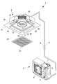
- FIG. 1 shows a perspective view of a ceiling-embedded air conditioner 1 according to the present embodiment
- FIG. 2 shows a longitudinal sectional view thereof.
- an example of the ceiling-embedded air conditioner 1 in which one indoor unit 3 is connected to the outdoor unit 2 is shown.
- the indoor unit 3 is hung and installed on a ceiling or the like in a room, and is connected to the outdoor unit 2 installed outdoors via the refrigerant pipe 4 and the electric wiring 5.
- the outdoor unit 2 is provided with equipment such as a refrigerant compressor 6, an outdoor heat exchanger 7, an outdoor fan 8, a control box 9, and a four-way switching valve (not shown).
- the outdoor unit 2 constitutes a refrigeration cycle together with an indoor heat exchanger 18 described later provided on the indoor unit 3 side, and has an adjusting function of the refrigerant supplied to the indoor unit 3.
- the indoor unit 3 includes a cabinet 10 whose lower portion is opened, and a substantially square ceiling panel 11 attached to the lower part of the cabinet 10.
- a bell mouth 13 forming an air suction port 12 and a drain pan 14 are installed at a lower part in the cabinet 10, and an air passage 15 is formed by a part of the drain pan 14.
- a turbofan 17 rotationally driven by a fan motor 16 is installed, and an indoor heat exchanger formed in a rectangular shape so as to surround the outer periphery of the turbofan 17.
- the reference numeral 18 is fixedly installed on the top plate side via a bracket (not shown).
- a rectangular air outlet 20 for blowing conditioned air along the four sides of the square-shaped ceiling panel 11 is provided to communicate with the air passage 15, and for drawing room air into the central portion.
- An opening 21 is provided.
- a suction grille 23 provided with an air filter 22 and the like is provided in the opening 21 so as to be able to move up and down via a wire 24 and the like.
- a wind direction adjusting louver 25 for adjusting the wind direction of the conditioned air blown out from the air outlet 20 is installed so as to be separately swingable.
- the turbo fan 17 has a main plate 27 provided with a hub 26 for fixing the rotation shaft 16A of the fan motor 16 at its central portion, and a shroud for forming a fluid flow path 28 opposed to the main plate 27.
- a plurality of blades 30 disposed between the shroud 29 and the main plate 27 are configured.
- the turbo fan 17 is disposed such that the shroud 29 side is opposed to the air suction port 12 of the bell mouth 13 and a part of the bell mouth 13 is overlapped with the inner periphery of the shroud 29.
- a recirculation passage 31 is formed, which circulates a portion along the back surface of the bell mouth 13 from the gap between the overlap portion of the bell mouth 13 and the shroud 29 to the inner surface 29 A of the shroud 29.
- the turbo fan 17 is a fan that rotates around the rotation shaft 16A of the fan motor 16, and discharges the air flowing in along the axial direction of the rotation shaft 16A in the radial direction intersecting the axial direction of the rotation shaft 16A.
- the axial direction of the rotation shaft 16A coincides with the vertical direction
- the radial direction intersecting the axial direction coincides with the horizontal direction.
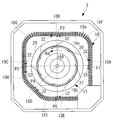
- FIG. 3 is a view of the turbo fan 17 and the indoor heat exchanger 18 shown in FIG.
- the indoor heat exchanger 18 is disposed to surround the outer periphery of the turbo fan 17 and has a heat transfer pipe 18 a and a plurality of fins 18 b attached to the heat transfer pipe 18 a.
- the indoor heat exchanger 18 includes a first flat portion 18A, a second flat portion 18B, a third flat portion 18C, a fourth flat portion 18D, a fifth flat portion 18E, and a first curved portion 18F.
- a second curved surface portion 18G, a third curved surface portion 18H, and a fourth curved surface portion 18I is disposed to surround the outer periphery of the turbo fan 17 and has a heat transfer pipe 18 a and a plurality of fins 18 b attached to the heat transfer pipe 18 a.
- the indoor heat exchanger 18 includes a first flat portion 18A, a second flat portion 18B, a third flat portion 18C, a fourth flat portion 18
- the first flat portion 18A is a portion disposed along a plane orthogonal to the radial direction at the closest position P1 to the blade 30 of the turbo fan 17.
- the second flat portion 18B is a portion disposed along a plane orthogonal to the radial direction at the closest position P2 to the blade 30 of the turbo fan 17.
- the third flat portion 18C is a portion disposed along a plane orthogonal to the radial direction at the closest position P3 to the blade 30 of the turbo fan 17.
- the fourth flat portion 18D is a portion disposed along a plane orthogonal to the radial direction at the closest position P3 to the blade 30 of the turbo fan 17.
- the fifth flat portion 18E is a portion disposed along a plane orthogonal to the radial direction at the closest position P5 to the blade 30 of the turbo fan 17.
- the first curved surface portion 18F is a portion connecting the first flat surface portion 18A and the second flat surface portion 18B
- the second curved surface portion 18G is a portion connecting the second flat surface portion 18B and the third flat surface portion 18C
- the third curved surface portion 18H is a portion connecting the third flat surface portion 18C and the fourth flat surface portion 18D
- the fourth curved surface portion 18I is a portion connecting the fourth flat surface portion 18D and the fifth flat surface portion 18E.
- FIG. 4 is a partially enlarged view of the indoor heat exchanger 18 and the straightening vane 32 shown in FIG.
- FIG. 5 is a partially enlarged view of the vicinity of the closest position P1 of the first plane portion 18A of FIG.
- a straightening vane 32 extending along an axis X1 parallel to the rotation axis 16A, and a straightening vane extending along an axis X2 parallel to the rotation axis 16A 32 and are attached.
- the two flow straightening plates 32 are attached to the inner peripheral side of the first flat portion 18A, and the two flow straightening plates 32 are attached to the inner peripheral side of the second flat portion 18B.
- the two flow straightening plates 32 are attached to the inner peripheral side of the third flat portion 18C.
- One straightening vane 32 is attached to the inner circumferential side of the fourth flat portion 18D, and one straightening vane 32 is attached to the inner circumferential side of the fifth flat portion 18E.
- the straightening vane 32 includes a base portion 32 a disposed along a plane orthogonal to the radial direction of the turbo fan 17, and a plate portion 32 b linearly projecting from the base portion 32 a toward the rotation shaft 16 A A pair of holding portions 32c that project in the opposite direction of the plate portion 32b from the base portion 32a, and a support portion 32d that protrudes in the opposite direction of the plate portion 32b from the base portion 32a.
- the straightening vane 32 is attached to the indoor heat exchanger 18 by holding the heat transfer pipe 18 a by the pair of holding parts 32 c in a state where the support part 32 d is supported by the heat transfer pipe 18 a.
- the first flat portion 18A is mounted in a state where the straightening vane 32A (first straightening vane) and the straightening vane 32B (second straightening vane) are disposed adjacent to each other. There is.
- the straightening vane 32A is attached to a first predetermined position on the upstream side of the rotational direction Rd of the turbo fan 17.
- an angle ⁇ 1 formed by a radial direction passing the closest position P1 of the first flat surface portion 18A and a radial direction passing the tip of the straightening vane 32A is in the range of 3 degrees to 7 degrees.
- Position. More preferably, the first predetermined position is a position where ⁇ 1 is 5 degrees.
- the straightening vane 32B is attached to a second predetermined position on the downstream side of the rotational direction Rd of the turbo fan 17.
- an angle ⁇ 2 formed by a radial direction passing through the closest position P1 of the first flat portion 18A and a radial direction passing through the tip of the straightening vane 32B is in the range of 15 ° to 20 °. Position.
- the distance L is the radial distance between the turbofan 17 and the indoor heat exchanger 18 at the closest position P1 of the first flat portion 18A to which the straightening vanes 32A and the straightening vanes 32B are attached.
- the distance l is a length projecting toward the rotation shaft 16A of the straightening vane 32A and the straightening vane 32B.
- the distance L and the distance l satisfy the relationships of the following equations (1) and (2).
- Formula (1) is a condition for suppressing the rise of the draft resistance by the straightening vane 32A.
- the equation (2) is a condition for reducing the velocity component of the rotational direction Rd of the blowing air of the turbo fan 17 at the closest position P1.
- the two flow straightening plates 32 attached to the first flat surface portion 18A have been described above, the two flow straightening plates 32 attached to the second flat surface portion 18B are also two flow straightening flow plates 32 attached to the first flat surface portion 18A. It becomes the same arrangement as.
- the two flow straightening plates 32 attached to the third flat surface portion 18C also have the same arrangement as the two flow straightening flow plates 32 attached to the first flat surface portion 18A.
- Two straightening vanes 32 are attached to each of the first flat portion 18A, the second flat portion 18B, and the third flat portion 18C, while one each of the fourth flat portion 18D and the fifth flat portion 18E is attached.
- the current plate 32 is attached. This is because the lengths of the fourth flat portion 18D and the fifth flat portion 18E are shorter than those of the first flat portion 18A, the second flat portion 18B, and the third flat portion 18C, and the blowout wind at the closest positions P4 and P5 is This is because the velocity component in the rotational direction Rd is small.
- FIG. 6 is a graph showing the sound pressure level of noise generated in the indoor unit 3 of the present embodiment.
- solid lines indicate sound pressure levels when a plurality of rectifying plates 32 are disposed on the inner peripheral side of the indoor heat exchanger 18 as shown in FIG. 3 of this embodiment, and broken lines indicate a plurality of The sound pressure level in the case where all of the rectifying plates 32 are not arranged is shown.
- FIG. 6 shows the relationship between the 1/3 octave band center frequency (Hz) and the sound pressure level (dB).
- the sound pressure level in the high frequency region (2 kHz to 4 kHz) that is easily recognized as noise is lower than that in the comparative example. This is because the current plate 32 is attached to the first predetermined position on the upstream side of the rotational direction Rd of the turbo fan 17 with respect to the closest positions P1, P2, and P3. It is considered that the cause is the decrease due to the turbulent flow generated in the straightening vane 32 before reaching the closest position P1, P2, P3.
- the closest position P1 to the blade 30 of the turbo fan 17 is on the first flat portion 18A, the second flat portion 18B, and the third flat portion 18C of the indoor heat exchanger 18.
- the current plate 32 is attached to a first predetermined position on the upstream side of the rotational direction Rd of the turbo fan 17. Therefore, the velocity component in the rotational direction Rd of the blowing air decreases due to the turbulent flow generated by the rectifying plate 32 before reaching the closest positions P1, P2 and P3, and the blowing wind is generated at the closest positions P1, P2 and P3.
- the blowing noise generated by collision with the fins 18 b is reduced.
- the first predetermined position is a radial direction passing the closest position P1 (P2, P3) of the first flat surface portion 18A (the second flat surface portion 18B, the third flat surface portion 18C) and a radial direction passing the tip of the rectifying plate 32A.
- This is a position where the angle ⁇ 1 formed by ⁇ is in the range of 3 degrees to 7 degrees. More preferably, the position is 5 degrees.
- the closest position P1 to the blade 30 of the turbo fan 17 is on the first flat portion 18A, the second flat portion 18B, and the third flat portion 18C of the indoor heat exchanger 18.
- the current plate 32 is attached to a second predetermined position on the downstream side of the rotational direction Rd of the turbo fan 17. Therefore, it is suppressed that the speed component of the rotational direction Rd of the blowing air rises again downstream of the rotational direction Rd of the turbo fan 17 with respect to the closest position P1, P2, P3, and the blowing air collides with the fin 18b. The blowing noise generated is reduced.
- the second predetermined position is a radial direction passing the closest position P1 (P2, P3) of the first flat surface portion 18A (the second flat surface portion 18B, the third flat surface portion 18C) and a radial direction passing the tip of the rectifying plate 32B.
- This is a position where the angle ⁇ 2 formed by ⁇ is in the range of not less than 15 degrees and not more than 20 degrees.
- the straightening vane 32 extends along the axes X1 and X2 parallel to the rotation shaft 16A of the turbo fan 17 and protrudes linearly toward the rotation shaft 16A. Therefore, the ventilation resistance is reduced as compared with the case where the turbo fan 17 is formed in a curved shape which is inclined in the direction opposite to the rotational direction Rd of the turbo fan 17 and bulges inward. Since the two straightening vanes 32 are disposed on the upstream side and the downstream side of the rotational direction Rd of the turbo fan 17 with the closest positions P1, P2 and P3 interposed therebetween, the closest positions P1, P2 and P3 are included.
- the air flow resistance is reduced compared to the case where three straightening vanes are arranged.
- the air conditioner 1 of the present embodiment it is possible to reduce the blowing noise generated due to the blowing wind colliding with the fins 18 b without largely increasing the ventilation resistance.
- the turbo at the closest position P1 (P2, P3) of the first flat portion 18A (the second flat portion 18B, the third flat portion 18C) to which the straightening vane 32A and the straightening vane 32B are attached.
- the distance between the fan 17 and the indoor heat exchanger 18 in the radial direction is L
- the length of the straightening plate 32A projecting toward the rotation shaft 16A is l, L / l ⁇ 3.5 and l ⁇ 7 mm. Fulfill.
- the distance L between the turbo fan 17 and the indoor heat exchanger 18 in the radial direction is 3.5 times or more of the length l of the straightening plate 32A and the straightening plate 32B protruding toward the rotation shaft 16A. And the rise of the draft resistance by the current plate 32B can be sufficiently suppressed.
- l By setting l to 7 mm or more, turbulent flow can be appropriately generated by the straightening vane 32A, and the velocity component of the rotational direction Rd of the blowing air at the closest position P1 (P2, P3) can be reduced.
Landscapes
- Engineering & Computer Science (AREA)
- Chemical & Material Sciences (AREA)
- Combustion & Propulsion (AREA)
- Mechanical Engineering (AREA)
- General Engineering & Computer Science (AREA)
- Physics & Mathematics (AREA)
- Thermal Sciences (AREA)
- Air-Conditioning Room Units, And Self-Contained Units In General (AREA)
- Air Filters, Heat-Exchange Apparatuses, And Housings Of Air-Conditioning Units (AREA)
- Air-Flow Control Members (AREA)
- Heat-Exchange Devices With Radiators And Conduit Assemblies (AREA)
Abstract
Priority Applications (4)
| Application Number | Priority Date | Filing Date | Title |
|---|---|---|---|
| EP18901027.5A EP3739268B1 (fr) | 2018-01-19 | 2018-11-09 | Climatiseur |
| ES18901027T ES2969560T3 (es) | 2018-01-19 | 2018-11-09 | Acondicionador de aire |
| AU2018402616A AU2018402616B2 (en) | 2018-01-19 | 2018-11-09 | Air conditioner |
| CN201880086535.1A CN111602006A (zh) | 2018-01-19 | 2018-11-09 | 空气调节机 |
Applications Claiming Priority (2)
| Application Number | Priority Date | Filing Date | Title |
|---|---|---|---|
| JP2018-007218 | 2018-01-19 | ||
| JP2018007218A JP7005355B2 (ja) | 2018-01-19 | 2018-01-19 | 空気調和機 |
Publications (1)
| Publication Number | Publication Date |
|---|---|
| WO2019142466A1 true WO2019142466A1 (fr) | 2019-07-25 |
Family
ID=67302204
Family Applications (1)
| Application Number | Title | Priority Date | Filing Date |
|---|---|---|---|
| PCT/JP2018/041713 WO2019142466A1 (fr) | 2018-01-19 | 2018-11-09 | Climatiseur |
Country Status (6)
| Country | Link |
|---|---|
| EP (1) | EP3739268B1 (fr) |
| JP (1) | JP7005355B2 (fr) |
| CN (1) | CN111602006A (fr) |
| AU (1) | AU2018402616B2 (fr) |
| ES (1) | ES2969560T3 (fr) |
| WO (1) | WO2019142466A1 (fr) |
Citations (3)
| Publication number | Priority date | Publication date | Assignee | Title |
|---|---|---|---|---|
| JPS6030921A (ja) * | 1983-07-29 | 1985-02-16 | Hitachi Ltd | 空気調和機 |
| JPH05187649A (ja) * | 1992-01-16 | 1993-07-27 | Mitsubishi Electric Corp | 天井埋込形空気調和機 |
| JP2001099436A (ja) | 1999-09-30 | 2001-04-13 | Fujitsu General Ltd | 天井埋込形空気調和機 |
Family Cites Families (9)
| Publication number | Priority date | Publication date | Assignee | Title |
|---|---|---|---|---|
| JPH0749295Y2 (ja) * | 1991-05-16 | 1995-11-13 | 三菱電機株式会社 | 天井埋込形空気調和機 |
| US5277547A (en) * | 1991-05-18 | 1994-01-11 | Usui Kokusai Sangyo Kaisha Ltd. | Motor fan unit |
| JP2000304347A (ja) * | 1999-04-22 | 2000-11-02 | Mitsubishi Electric Corp | 熱交換ユニット |
| CN2416419Y (zh) * | 2000-02-28 | 2001-01-24 | 大金工业株式会社 | 顶置式空调机 |
| JP3918111B2 (ja) * | 2002-03-13 | 2007-05-23 | 三菱電機株式会社 | 空気調和機 |
| JP2006226595A (ja) * | 2005-02-17 | 2006-08-31 | Matsushita Electric Ind Co Ltd | 空気調和機 |
| KR100782195B1 (ko) * | 2006-08-10 | 2007-12-04 | 엘지전자 주식회사 | 공기 조화기 |
| JP6135125B2 (ja) * | 2012-12-26 | 2017-05-31 | ダイキン工業株式会社 | 室内機 |
| JP2016142431A (ja) * | 2015-01-30 | 2016-08-08 | ジョンソンコントロールズ ヒタチ エア コンディショニング テクノロジー(ホンコン)リミテッド | 空気調和機 |
-
2018
- 2018-01-19 JP JP2018007218A patent/JP7005355B2/ja active Active
- 2018-11-09 EP EP18901027.5A patent/EP3739268B1/fr active Active
- 2018-11-09 WO PCT/JP2018/041713 patent/WO2019142466A1/fr unknown
- 2018-11-09 ES ES18901027T patent/ES2969560T3/es active Active
- 2018-11-09 AU AU2018402616A patent/AU2018402616B2/en active Active
- 2018-11-09 CN CN201880086535.1A patent/CN111602006A/zh active Pending
Patent Citations (3)
| Publication number | Priority date | Publication date | Assignee | Title |
|---|---|---|---|---|
| JPS6030921A (ja) * | 1983-07-29 | 1985-02-16 | Hitachi Ltd | 空気調和機 |
| JPH05187649A (ja) * | 1992-01-16 | 1993-07-27 | Mitsubishi Electric Corp | 天井埋込形空気調和機 |
| JP2001099436A (ja) | 1999-09-30 | 2001-04-13 | Fujitsu General Ltd | 天井埋込形空気調和機 |
Non-Patent Citations (1)
| Title |
|---|
| See also references of EP3739268A4 |
Also Published As
| Publication number | Publication date |
|---|---|
| ES2969560T3 (es) | 2024-05-21 |
| EP3739268A4 (fr) | 2021-03-17 |
| JP2019124437A (ja) | 2019-07-25 |
| AU2018402616A1 (en) | 2020-09-03 |
| EP3739268C0 (fr) | 2024-01-03 |
| EP3739268B1 (fr) | 2024-01-03 |
| CN111602006A (zh) | 2020-08-28 |
| EP3739268A1 (fr) | 2020-11-18 |
| AU2018402616B2 (en) | 2021-07-08 |
| JP7005355B2 (ja) | 2022-02-10 |
Similar Documents
| Publication | Publication Date | Title |
|---|---|---|
| JP6248486B2 (ja) | 空気調和機のダクト型室内機 | |
| JP6324316B2 (ja) | 空気調和機の室内機 | |
| JP6311427B2 (ja) | 空気調和装置 | |
| JP6354279B2 (ja) | 空気調和装置 | |
| JP2010078274A (ja) | 床置型空気調和機の室内機 | |
| JP5720600B2 (ja) | 室内機 | |
| JP6237435B2 (ja) | 空気調和装置 | |
| JP6758992B2 (ja) | 室内機および空気調和機 | |
| JP6524243B2 (ja) | 空気調和機の室外機 | |
| JP2014031994A (ja) | 空気調和機 | |
| WO2019142466A1 (fr) | Climatiseur | |
| JP2016188578A (ja) | 送風装置 | |
| JP6363033B2 (ja) | 空気調和機の室内機およびこれを備えた空気調和機 | |
| CN116391097A (zh) | 室内机和制冷循环装置 | |
| KR102522048B1 (ko) | 천장형 공기조화기 | |
| WO2023152938A1 (fr) | Unité intérieure et climatiseur | |
| JP2016132991A (ja) | 送風装置 | |
| WO2023002956A1 (fr) | Climatiseur | |
| JP7370466B2 (ja) | 空気調和機の室外機 | |
| JP2018025354A (ja) | 室内機および空気調和機 | |
| JP2022069998A (ja) | 空気調和機の室内機 | |
| WO2019198150A1 (fr) | Climatiseur | |
| WO2020202297A1 (fr) | Climatiseur | |
| JP6211101B2 (ja) | 遠心ファン、空気調和装置及び空気清浄装置 | |
| JP2021162173A (ja) | 空気調和機の室外機 |
Legal Events
| Date | Code | Title | Description |
|---|---|---|---|
| 121 | Ep: the epo has been informed by wipo that ep was designated in this application |
Ref document number: 18901027 Country of ref document: EP Kind code of ref document: A1 |
|
| NENP | Non-entry into the national phase |
Ref country code: DE |
|
| ENP | Entry into the national phase |
Ref document number: 2018901027 Country of ref document: EP Effective date: 20200813 |
|
| ENP | Entry into the national phase |
Ref document number: 2018402616 Country of ref document: AU Date of ref document: 20181109 Kind code of ref document: A |