WO2019138641A1 - ガス監視システム及びガス監視方法 - Google Patents
ガス監視システム及びガス監視方法 Download PDFInfo
- Publication number
- WO2019138641A1 WO2019138641A1 PCT/JP2018/039285 JP2018039285W WO2019138641A1 WO 2019138641 A1 WO2019138641 A1 WO 2019138641A1 JP 2018039285 W JP2018039285 W JP 2018039285W WO 2019138641 A1 WO2019138641 A1 WO 2019138641A1
- Authority
- WO
- WIPO (PCT)
- Prior art keywords
- image
- gas
- monitoring system
- gas monitoring
- target area
- Prior art date
- Legal status (The legal status is an assumption and is not a legal conclusion. Google has not performed a legal analysis and makes no representation as to the accuracy of the status listed.)
- Ceased
Links
Images




Classifications
-
- G—PHYSICS
- G01—MEASURING; TESTING
- G01M—TESTING STATIC OR DYNAMIC BALANCE OF MACHINES OR STRUCTURES; TESTING OF STRUCTURES OR APPARATUS, NOT OTHERWISE PROVIDED FOR
- G01M3/00—Investigating fluid-tightness of structures
- G01M3/02—Investigating fluid-tightness of structures by using fluid or vacuum
-
- G—PHYSICS
- G01—MEASURING; TESTING
- G01M—TESTING STATIC OR DYNAMIC BALANCE OF MACHINES OR STRUCTURES; TESTING OF STRUCTURES OR APPARATUS, NOT OTHERWISE PROVIDED FOR
- G01M3/00—Investigating fluid-tightness of structures
- G01M3/38—Investigating fluid-tightness of structures by using light
Definitions
- the present invention relates to a gas monitoring system and a gas monitoring method.
- gas monitoring systems are used in gas processing plants for processing and pipeline delivery of natural gas.
- the gas monitoring system for example, captures the inside of the plant with an infrared camera, transmits the captured image to a terminal for monitoring through a public line, and monitors a gas leak in the plant based on the transmitted image. .
- An object of the present invention is to provide a gas monitoring system and a gas monitoring method capable of securing security and reducing a load on a line due to communication capacity.
- the gas monitoring system in the present invention is An imaging unit that captures an image of a target area to which gas may leak;
- a communication unit that transmits, via a public line, information indicating the image of the target area and incidental information indicating information related to the target area;
- Based on the peripheral image representing the periphery of the target region, the information indicating the image of the target region received via the public line, and the supplementary information, the peripheral image and the image of the target region are An image combining unit to combine, Equipped with
- the gas monitoring method in the present invention is Take an image of the target area where gas may leak,
- the information indicating the image of the target area and the incidental information indicating the information related to the target area are transmitted through a public line, Based on the peripheral image representing the periphery of the target region, the information indicating the image of the target region received via the public line, and the supplementary information, the peripheral image and the image of the target region are Synthesize.
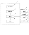
- FIG. 1 is a block diagram schematically showing the configuration of a gas monitoring system 100 according to an embodiment of the present invention.
- the gas monitoring system 100 includes a terminal 1, a terminal 2, a gas imaging device 3 and a peripheral sensor 4.
- FIG. 2 is a block diagram schematically showing the configuration of the gas imaging device 3 and the peripheral sensor 4.
- the gas imaging device 3 is provided at one or more places in the plant.
- the gas imaging device 3 includes an infrared imaging unit 31 (corresponding to “far infrared camera” of the present invention and referred to as an FIR camera), an image processing unit 32, a control unit 33, and storage. And a unit 34. Further, the peripheral sensor 4 is connected to the gas imaging device 3 by an interface such as USB (Universal Serial Bus).
- the image processing unit 32 is realized by a central processing unit (CPU), a read only memory (ROM), a random access memory (RAM), a hard disk drive (HDD) or the like, and performs image processing of data.
- the control unit 33 includes a CPU, a ROM, a RAM, and the like. The CPU provided in the control unit 33 reads out a program corresponding to the processing content from the ROM, expands it in the RAM, and centrally controls the operation of each block of the gas imaging device 3 in cooperation with the expanded program.
- the infrared imaging unit 31 has an optical filter for imaging a predetermined gas.
- the infrared imaging unit 31 images infrared light from a target area where gas may leak, under the control of the control unit 33.
- the infrared imaging unit 31 is disposed, for example, with an imaging optical system (not shown) for forming an infrared optical image of a target area on a predetermined imaging surface and a light receiving surface in agreement with the imaging surface.
- an infrared image sensor (not shown) for converting an infrared optical image of the image sensor into an electrical signal.
- the gas may be any kind of gas having a property of absorbing infrared rays, such as a flammable gas, a toxic gas and a vapor of an organic solvent.
- FIG. 3 shows the amount of infrared radiation V (Tb) emitted from the background, the amount of infrared radiation absorbed by the gas as ⁇ V (Tb), and the amount of infrared radiation V (Tg) emitted from the gas.
- V (T) is the black body radiance at the absolute temperature T (K).
- the gas is the sum of the amount of infrared radiation V (Tb) emitted from the background, the amount of infrared radiation (1- ⁇ ) V (Tb) emitted from the background and transmitted through the gas, and the amount of infrared radiation V (Tg) emitted from the gas It is detected based on the difference with the amount of Therefore, the range of gas detection is a background temperature image which is an image based on the infrared ray amount V (Tb), and a gas-containing image which is an image based on the infrared ray amount ((1- ⁇ ) V (Tb) + V (Tg)) Is determined as an image from which the difference of Note that noise components may be removed from the extracted image.
- FIG. 4 is a diagram showing an example of the target area A and its periphery A1 in the plant.
- FIG. 4 shows a reference position B in the periphery A1, a gas cloud A2 in the target area A, and a gas leakage position C in the target area A.
- the reference position B may be any place in the plant, for example, it is preferable to be a place that is easy to identify in the plant.
- the gas leakage position C is determined from, for example, an image of the gas cloud A2, a wind direction, a wind speed, and the like.
- the image processing unit 32 generates a heat distribution image (temperature information) of the target area A by performing image processing on data output from the infrared image sensor. Specifically, the infrared image sensor measures the amount of infrared radiation (luminance information) emitted from the target area A. The image processing unit 32 converts the result measured by the infrared image sensor into the temperature of the target area A with reference to the correlation between the infrared amount (brightness information) and the temperature, and the heat distribution image (temperature information) Generate The image processing unit 32 performs gas visualization processing (extraction) under predetermined image processing conditions from the infrared ray amount (luminance information) measured by the infrared image sensor.
- gas visualization processing extraction
- the control unit 33 outputs the image of the visualized gas cloud A2 in the target region A (corresponding to the “image of the target region” in the present invention) to the storage unit 34.
- an image of the gas cloud A2 will be described as two-dimensional data.
- the image of the gas cloud A2 may be three-dimensional data (point cloud data).
- the peripheral sensor 4 includes, for example, a distance meter 4a, an anemometer 4b, a thermometer 4c, and a vibration meter 4d.
- the peripheral sensor 4 outputs each measurement result to the control unit 33.
- the control unit 33 acquires incidental information indicating information related to the target area A based on the measurement result of the peripheral sensor 4.
- the distance meter 4a is connected to the control unit 33, and according to the control of the control unit 33, the three-dimensional coordinates (xb, yb, zb) of the reference position B and the three-dimensional coordinates (xc, yc, xc) of the gas leakage position C in the plant. Measure).
- the distance meter 4a is, for example, an optical, ultrasonic, or laser light meter.
- an optical distance meter 4a there is, for example, a stereo camera.
- the measurement of the reference position B or the like by the distance meter 4a may be performed automatically, or may be performed by the user's remote control.
- the wind direction anemometer 4 b is connected to the control unit 33, and is a device that measures the wind direction and the wind speed according to the control of the control unit 33.
- the wind direction and anemometer 4 b includes, for example, an instrument that measures wind direction and wind speed, such as a windmill type (propeller type) and an ultrasonic type.
- the thermometer 4 c is a device connected to the control unit 33 to measure the outside air temperature according to the control of the control unit 33.
- the outside air temperature is, for example, the ambient temperature around the gas imaging device 3.
- the vibration meter 4 d is connected to the control unit 33, and is a device that measures the vibration state of the gas imaging device 3 according to the control of the control unit 33.
- a known instrument such as a mechanical type, a magnetic type, a piezoelectric type, an optical type, or an electromagnetic wave type is used.
- the control unit 33 acquires incidental information of the target area A based on the measurement result of the peripheral sensor 4 described above.
- the three-dimensional coordinates of the reference position B and the three-dimensional coordinates of the gas leakage position C, which are incidental information, are information used when combining the image of the surrounding area A1 and the image of the gas cloud A2 (described later).
- environmental conditions such as the wind speed, the wind direction, the difference between the temperature of the target area A and the outside air temperature, which is incidental information, and the vibration state of the infrared imaging unit 31 are information for increasing the accuracy of the image of the gas cloud A2.
- the incidental information of the target area A includes the size of the gas cloud A2.
- the control unit 33 calculates the size (for example, the size in the x direction, the y direction, and the z direction) of the gas cloud A2 based on, for example, the image of the gas cloud A2.
- the size of the gas cloud A2 is information used when combining the image of the periphery A1 and the image of the gas cloud A2.
- the control unit 33 refers to the relative positional relationship between the coordinates of the reference position B in the image of the periphery A1 and the three-dimensional coordinates of the reference position B in the plant based on the three-dimensional coordinates of the gas leakage position C in the plant.
- the coordinates of the gas leakage position C in the image of the surrounding area A1 are calculated. Since each incidental information described above is text data, the size (data capacity) is small.
- the storage unit 34 is a circuit that is connected to the control unit 33 and stores various predetermined data and various predetermined programs according to the control of the control unit 33.
- Various predetermined data are an image of the gas cloud A2 and incidental information.
- the various predetermined programs include, for example, a control processing program such as an imaging program for imaging the target area A.
- the storage unit 34 includes, for example, a ROM (Read Only Memory), which is a nonvolatile storage element, and an EEPROM (Electrically Erasable Programmable ROM), which is a rewritable nonvolatile storage element.
- Storage unit 34 includes a RAM (Random Access Memory) as a working memory of so-called control unit 33 that stores data and the like generated during execution of a predetermined program.
- the control unit 33 outputs the image of the gas cloud A2 and the incidental information stored in the storage unit 34 to the terminal 1.
- the terminal 1 is provided, for example, outside the plant or in the plant.
- the terminal 1 is a personal computer for periodically acquiring an image of the gas cloud A 2 and incidental information from the gas imaging device 3 and uploading the image to the cloud 5.
- the terminal 1 includes a control unit 11, a communication unit 12, and a storage unit 13.
- the control unit 11 controls the communication unit 12 and the storage unit 13 in an integrated manner.
- the control unit 11 controls the communication unit 12 and the storage unit 13 to upload the image of the gas cloud A2 and the incidental information as information indicating the image of the target area A to the cloud 5 via the public line.
- the control unit 11 controls the communication unit 12 so as to automatically perform the upload.
- the size of the image of gas cloud A2 is much smaller than the size of the image of surrounding area A1, and the size of the incidental information is also small, so when uploading the image and incidental information of gas cloud A2, depending on the communication capacity There is no burden on the line.
- a cloud storage 51 (external storage device) that can be used from the terminal 1 and the terminal 2 via a network is provided.
- the cloud storage 51 stores an image of the gas cloud A2 and incidental information.
- the terminal 2 is provided, for example, outside the plant or in the plant.
- the terminal 1 and the terminal 2 may be provided at the same place.
- the terminal 2 is a personal computer that receives the image of the gas cloud A2 and the incidental information from the cloud 5, refers to the incidental information, and combines the image of the surrounding area A1 and the image of the gas cloud A2.
- the terminal 2 includes a control unit 21, a communication unit 22, a storage unit 23, and an image combining unit 24.
- the control unit 21 centrally controls the control unit 21, the communication unit 22, the storage unit 23, and the image combining unit 24.
- the control unit 21 controls the communication unit 22 and the storage unit 23 to download the image of the gas cloud A2 and the incidental information from the cloud 5 through the public line.
- the control unit 21 controls the communication unit 22 so as to automatically perform the download. In the case of downloading the image of the gas cloud A2 and the incidental information, as in the case of the above uploading, the communication capacity does not burden the circuit.
- the storage unit 23 is provided in an environment not connected to a public line.
- the storage unit 23 stores an image of the surrounding area A1.
- the image of the surrounding area A1 is two-dimensional data in which the surrounding area A1 is schematically illustrated.
- the image of the surrounding area A1 may be three-dimensional data.
- the image synthesis unit 24 downloads incidental information (3 of the reference position B) downloaded from the cloud 5 based on the image of the gas cloud A2 downloaded from the cloud 5 and the image of the surroundings A1 read from the storage unit 23.
- the image of the periphery A1 and the image of the gas cloud A2 are synthesized with reference to the three-dimensional coordinates of the gas leak position C and the three-dimensional coordinates of the gas leak position C in the image of the periphery A1.
- the control unit 21 outputs a composite image of the image of the periphery A1 and the image of the gas cloud A2 to the display unit 25.
- the composite image is two-dimensional data.
- the display unit 25 displays a composite image.
- the gas leakage position C may be hidden by the foreground and may not be displayed in the composite image.
- the display unit 25 changes the viewpoint (the position of the infrared imaging unit 31) between the foreground and the gas leakage position C by the operation unit (not shown), thereby causing gas leakage.
- Position C is displayed.
- the gas leakage position C is displayed by freely moving the viewpoint on the three-dimensional coordinates by the operation unit.
- FIG. 5 is a flowchart showing an image synthesis process in the gas monitoring system 100.
- the present process is started by activation of the gas imaging device 3 and the peripheral sensor 4.
- the image of the periphery A1 is stored in advance in the storage unit 23 provided in an environment not connected to the public line.
- step S100 the infrared imaging unit 31 captures an infrared ray from the target area A.
- step S ⁇ b> 110 the control unit 33 acquires incidental information of the target area A based on the measurement result of the peripheral sensor 4.
- step S120 the image processing unit 32 extracts an image of the gas cloud A2 from the heat distribution image of the target area A.
- step S130 the image of the gas cloud A2 and the incidental information are uploaded from the terminal 1 to the cloud 5 via the public line.
- step S140 the image of the gas cloud A2 and the incidental information are downloaded from the cloud 5 to the terminal 2 via the public line.
- step S150 the image combining unit 24 combines the image of the surrounding area A1 and the image of the gas cloud A2.
- step S160 the display unit 25 displays a composite image of the image of the periphery A1 and the image of the gas cloud A2.
- the gas imaging device 3 for capturing an image of the target area A to which the gas may leak, and the environment not connected to the public line are provided around the target area A.
- a storage unit 13 for storing an image of A1, a communication unit 12 for transmitting an image of gas cloud A2 and incidental information via a public line, an image of surrounding area A1, and a gas cloud received via a public line
- an image combining unit configured to combine the image of the surrounding area A1 and the image of the gas cloud A2 based on the image of A2 and the incidental information.
- the image of the gas cloud A2 is exemplified as the information indicating the image of the target area A, but the present invention is not limited to this and may be text data.
- the text data is information for creating an image of the gas cloud A2, and is information including, for example, the shape of the gas cloud A2 schematically showing the gas cloud A2, luminance information of the shape, and the like. Since the size of the text data is smaller than the size of the image of the gas cloud A2, the load on the line by the communication capacity can be further reduced.
- the reference position B and the gas leakage position C are measured by the distance meter 4a, but the present invention is not limited to this, for example, based on the heat distribution image acquired by the infrared imaging unit 31 It may be calculated. Also, the reference position B or the like may be measured based on both the distance meter 4a and the heat distribution image.
- the image of the gas cloud A2 when the image of the gas cloud A2 is extracted, the image of the surrounding area A1 and the image of the gas cloud A2 are combined, and the combined image is displayed, the user is notified of gas detection. An alarm may be output.
- the present invention is not limited thereto, for example, the image of the periphery A1 is data obtained by photographing the periphery A1 It is also good.
- the incidental information of the target area A the coordinates of the reference position B and the like are given as an example, but the present invention is not limited thereto.
- the temperature of gas piping, heat of vaporization of gas, etc. It may include disturbance information.
- the disturbance information it is possible to suppress the decrease in the accuracy (resolution) of the image of the gas cloud A2.
- any of the above-described embodiments is merely an example of implementation for carrying out the present invention, and the technical scope of the present invention should not be interpreted in a limited manner by these. That is, the present invention can be implemented in various forms without departing from the scope or main features of the present invention.
- the present invention is suitably used for a gas monitoring system that is required to secure security and reduce the burden on a line due to communication capacity.
Landscapes
- Physics & Mathematics (AREA)
- General Physics & Mathematics (AREA)
- Alarm Systems (AREA)
- Emergency Alarm Devices (AREA)
Abstract
ガス監視システムは、セキュリティを確保するとともに、通信容量による回線への負担を軽減することができるものであって、ガスが漏洩しうる対象領域の画像を撮像する撮像部と、対象領域の画像を示す情報および当該対象領域に関係する情報を示す付帯情報を、公衆回線を介して送信する通信部と、対象領域の周辺を表す周辺の画像、並びに、公衆回線を介して受信された対象領域の画像を示す情報および付帯情報に基づいて、周辺の画像と対象領域の画像とを合成する画像合成部と、を備える。
Description
本発明は、ガス監視システム及びガス監視方法に関する。
例えば、ガス監視システムは、天然ガスを処理してパイプラインで送出するためのガス処理プラントに利用されている。ガス監視システムは、例えば、プラント内を赤外線カメラで撮影し、撮像した画像を公衆回線で監視用の端末に送信し、送信された画像に基づいて、プラント内のガス漏れを監視するものである。
ところで、プラント内を撮影した画像を公衆回線で送信することは、セキュリティを確保する観点から好ましくないとされている。また、通信容量が大きい場合には、公衆回線に通信容量による負担をかけるため、好ましくない。
例えば、ガス監視システムではないが、撮影装置により順次取得されるフレームの画像を背景画像と抽出画像とに分け、背景画像と抽出画像とを通信回線を介して別々のサーバーに送信するシステムがある(例えば、特許文献1参照)。
しかしながら、上記の特許文献1に記載されたシステムでは、セキュリティを確保することについての記載はなく、また、背景画像及び抽出画像を別々のサーバーに送信する際の通信容量は、フレームの画像をサーバーに送信する際の通信容量に対して大差がないため、通信容量による回線への負担を軽減することができないという問題点があった。
本発明は、セキュリティを確保するとともに、通信容量による回線への負担を軽減することができるガス監視システム及びガス監視方法を提供することを目的とする。
上記の目的を達成するため、本発明におけるガス監視システムは、
ガスが漏洩しうる対象領域の画像を撮像する撮像部と、
前記対象領域の画像を示す情報および当該対象領域に関係する情報を示す付帯情報を、公衆回線を介して送信する通信部と、
前記対象領域の周辺を表す周辺の画像、並びに、前記公衆回線を介して受信された前記対象領域の画像を示す情報および前記付帯情報に基づいて、前記周辺の画像と前記対象領域の画像とを合成する画像合成部と、
を備える。
ガスが漏洩しうる対象領域の画像を撮像する撮像部と、
前記対象領域の画像を示す情報および当該対象領域に関係する情報を示す付帯情報を、公衆回線を介して送信する通信部と、
前記対象領域の周辺を表す周辺の画像、並びに、前記公衆回線を介して受信された前記対象領域の画像を示す情報および前記付帯情報に基づいて、前記周辺の画像と前記対象領域の画像とを合成する画像合成部と、
を備える。
また、本発明におけるガス監視方法は、
ガスが漏洩しうる対象領域の画像を撮像し、
前記対象領域の画像を示す情報および当該対象領域に関係する情報を示す付帯情報を、公衆回線を介して送信し、
前記対象領域の周辺を表す周辺の画像、並びに、前記公衆回線を介して受信された前記対象領域の画像を示す情報および前記付帯情報に基づいて、前記周辺の画像と前記対象領域の画像とを合成する。
ガスが漏洩しうる対象領域の画像を撮像し、
前記対象領域の画像を示す情報および当該対象領域に関係する情報を示す付帯情報を、公衆回線を介して送信し、
前記対象領域の周辺を表す周辺の画像、並びに、前記公衆回線を介して受信された前記対象領域の画像を示す情報および前記付帯情報に基づいて、前記周辺の画像と前記対象領域の画像とを合成する。
本発明によれば、セキュリティを確保するとともに、通信容量による回線への負担を軽減することができる。
以下、本発明の実施の形態について、図面を参照しながら説明する。
図1は、本発明の実施の形態におけるガス監視システム100の構成を概略的に示すブロック図である。
図1は、本発明の実施の形態におけるガス監視システム100の構成を概略的に示すブロック図である。
図1に示すように、ガス監視システム100は、端末1、端末2、ガス撮像装置3および周辺センサー4を備える。
先ず、ガス撮像装置3および周辺センサー4について説明する。図2は、ガス撮像装置3および周辺センサー4の構成を概略的に示すブロック図である。ガス撮像装置3は、プラント内の一以上の箇所に設けられている。
ガス撮像装置3は、図2に示すように、赤外線撮像部31(本発明の「遠赤外線カメラ」に対応、FIRカメラと称される)と、画像処理部32と、制御部33と、記憶部34とを備える。また、ガス撮像装置3にはUSB(Universal Serial Bus)などのインターフェースにより周辺センサー4が接続される。画像処理部32は、CPU(Central Processing Unit)、ROM(Read Only Memory)、RAM(Random Access Memory)、及び、HDD(Hard Disk Drive)等によって実現され、データの画像処理を行う。また、制御部33は、CPU、ROM、RAM等を備える。制御部33に備えられるCPUは、ROMから処理内容に応じたプログラムを読み出してRAMに展開し、展開したプログラムと協働してガス撮像装置3の各ブロックの動作を集中制御する。
赤外線撮像部31は、予め定められたガスを撮像するための光学フィルターを有する。赤外線撮像部31は、制御部33の制御に従って、ガスが漏洩しうる対象領域からの赤外線を撮像する。赤外線撮像部31は、例えば、対象領域の赤外線光学像を所定の結像面上に結像する結像光学系(図示略)と、結像面に受光面を一致させて配置され、対象領域の赤外線光学像を電気的な信号に変換する赤外線イメージセンサー(図示略)とを備える。ここで、ガスは、可燃性ガス、毒性ガスおよび有機溶剤の蒸気など、赤外線を吸収する性質を有する気体であればどのような種類の気体でもよい。
図3を参照してガス検知の原理について説明する。ガスは、背景の温度に応じて放射される赤外線の一部を吸収する。図3に、背景から放射される赤外線量V(Tb)、ガスで吸収される赤外線量をαV(Tb)、ガスから放射される赤外線量V(Tg)で示す。ここで、V(T)は、絶対温度T(K)における黒体放射輝度である。
ガスは、背景から放射される赤外線量V(Tb)と、背景から放射され、ガスを透過する赤外線量(1-α)V(Tb)およびガスから放射される赤外線量V(Tg)を合算した量との差異に基づいて検知される。したがって、ガス検知の範囲は、赤外線量V(Tb)に基づく画像である背景温度画像と、赤外線量((1-α)V(Tb)+V(Tg))に基づく画像であるガスあり画像との差異を抽出した画像として定められる。なお、抽出された画像からノイズ成分が除去されてもよい。
図4は、プラントにおける対象領域Aおよびその周辺A1の一例を示す図である。図4に、周辺A1における基準位置B、対象領域Aにおけるガス雲A2、および、対象領域Aにおけるガス漏洩位置Cを示す。なお、基準位置Bは、プラント内であればどのような場所であってもよいが、例えば、プラント内において識別し易い場所であることが好ましい。また、ガス漏洩位置Cは、例えば、ガス雲A2の画像、風向、風速などから定められる。
画像処理部32は、赤外線イメージセンサーから出力されるデータの画像処理を行うことで、対象領域Aの熱分布画像(温度情報)を生成する。具体的には、赤外線イメージセンサーは、対象領域Aから放出される赤外線量(輝度情報)を計測する。画像処理部32は、赤外線イメージセンサーにより計測された結果を、赤外線量(輝度情報)と温度との相関関係を参照して対象領域Aの温度に変換して、熱分布画像(温度情報)を生成する。画像処理部32は、赤外線イメージセンサーにより計測された赤外線量(輝度情報)から予め定められた画像処理条件でガスの可視化処理(抽出)を行う。制御部33は、対象領域Aにおける可視化されたガス雲A2の画像(本発明の「対象領域の画像」に対応)を記憶部34へ出力する。以下、ガス雲A2の画像を2次元データとして説明する。なお、ガス雲A2の画像は3次元データ(点群データ)であってもよい。
周辺センサー4は、例えば、距離計4a、風向風速計4b、温度計4cおよび振動計4dを有する。周辺センサー4は、それぞれの計測結果を制御部33に出力する。制御部33は、周辺センサー4の計測結果に基づいて対象領域Aに関係する情報を示す付帯情報を取得する。
距離計4aは、制御部33に接続され、制御部33の制御に従って、プラントにおける基準位置Bの3次元座標(xb,yb,zb)およびガス漏洩位置Cの3次元座標(xc、yc、xc)を計測する。距離計4aは、例えば、光学式、超音波式およびレーザ光式等の計器である。なお、光学式の距離計4aとしては、例えばステレオカメラがある。距離計4aによる基準位置B等の計測は、自動的に行われてもよく、また、ユーザーの遠隔操作により行われてもよい。
風向風速計4bは、制御部33に接続され、制御部33の制御に従って、風向および風速を計測する装置である。風向風速計4bは、例えば、風車式(プロペラ式)および超音波式等の風向および風速を計測する計器を備えている。
温度計4cは、制御部33に接続され、制御部33の制御に従って、外気温度を計測する装置である。ここで、外気温度は、例えばガス撮像装置3の周辺気温である。
振動計4dは、制御部33に接続され、制御部33の制御に従って、ガス撮像装置3の振動状態を計測する装置である。振動計4dには、例えば、機械式、磁気式、圧電式、光学式、電磁波式などの公知の計器が用いられる。
制御部33は、上記する周辺センサー4の計測結果に基づいて対象領域Aの付帯情報を取得する。付帯情報である基準位置Bの3次元座標およびガス漏洩位置Cの3次元座標は、周辺A1の画像とガス雲A2の画像とを合成する場合に用いられる情報である(後述する)。また、付帯情報である風速、風向、対象領域Aの温度と外気温度との差、および、赤外線撮像部31の振動状態などの環境条件は、ガス雲A2の画像の精度上げるための情報である。また、対象領域Aの付帯情報には、ガス雲A2の大きさが含まれる。制御部33は、例えばガス雲A2の画像に基づいてガス雲A2の大きさ(例えば、x方向、y方向及びz方向における大きさ)を算出する。ガス雲A2の大きさは、周辺A1の画像とガス雲A2の画像とを合成する場合に用いられる情報である。制御部33は、プラントにおけるガス漏洩位置Cの3次元座標に基づいて、周辺A1の画像における基準位置Bの座標とプラントにおける基準位置Bの3次元座標との相対的な位置関係を参照して、周辺A1の画像におけるガス漏洩位置Cの座標を算出する。上記するそれぞれの付帯情報はテキストデータであるため、サイズ(データ容量)は小さい。
記憶部34は、制御部33に接続され、制御部33の制御に従って、各種の所定のデータおよび各種の所定のプログラムを記憶する回路である。各種の所定のデータは、ガス雲A2の画像および付帯情報である。各種の所定プログラムには、例えば、対象領域Aを撮像するための撮像プログラム等の制御処理プログラムが含まれる。記憶部34は、例えば、不揮発性の記憶素子であるROM(Read Only Memory)や書き換え可能な不揮発性の記憶素子であるEEPROM(Electrically Erasable Programmable ROM)等を備える。記憶部34は、所定のプログラムの実行中に生じるデータ等を記憶するいわゆる制御部33のワーキングメモリとなるRAM(Random Access Memory)等を含む。
制御部33は、記憶部34に記憶されているガス雲A2の画像および付帯情報を端末1に出力する。
端末1は、例えば、プラント外またはプラント内に設けられている。端末1は、ガス雲A2の画像および付帯情報をガス撮像装置3から定期的に取得し、クラウド5にアップロードするためのパーソナルコンピューターである。端末1は、制御部11、通信部12および記憶部13を有している。制御部11は、通信部12および記憶部13を統括的に制御する。制御部11は、通信部12及び記憶部13を制御して、対象領域Aの画像を示す情報としてのガス雲A2の画像および付帯情報を、公衆回線を介してクラウド5にアップロードする。制御部11は、アップロードを自動的に行うように通信部12を制御する。なお、ガス雲A2の画像のサイズは周辺A1の画像のサイズに対して大幅に小さく、また、付帯情報のサイズも小さいため、ガス雲A2の画像および付帯情報をアップロードする場合に、通信容量による回線への負担がかからない。
クラウド5上には、端末1及び端末2からネットワークを経由して利用できるクラウドストレージ51(外部記憶装置)が設けられている。クラウドストレージ51には、ガス雲A2の画像および付帯情報が記憶される。
端末2は、例えば、プラント外またはプラント内に設けられている。端末1と端末2とは同じ場所に設けられてもよい。端末2は、ガス雲A2の画像および付帯情報をクラウド5から受信して、付帯情報を参照して、周辺A1の画像とガス雲A2の画像との合成を行うパーソナルコンピューターである。端末2は、制御部21、通信部22、記憶部23および画像合成部24を有している。制御部21は、制御部21、通信部22、記憶部23および画像合成部24を統括的に制御する。制御部21は、通信部22および記憶部23を制御して、公衆回線を介してクラウド5からガス雲A2の画像および付帯情報をダウンロードする。制御部21は、ダウンロードを自動的に行うように通信部22を制御する。ガス雲A2の画像および付帯情報をダウンロードする場合も、上記のアップロードする場合と同様に、通信容量による回線への負担がかからない。
記憶部23は、公衆回線に接続されていない環境に設けられている。記憶部23は、周辺A1の画像を記憶している。周辺A1の画像は、当該周辺A1を模式化した2次元データである。なお、周辺A1の画像は3次元データであってもよい。
画像合成部24は、クラウド5からダウンロードされたガス雲A2の画像、並びに、記憶部23から読み出された周辺A1の画像に基づいて、クラウド5からダウンロードされた付帯情報(基準位置Bの3次元座標、ガス漏洩位置Cの3次元座標、周辺A1の画像におけるガス漏洩位置Cの3次元座標)を参照して、周辺A1の画像とガス雲A2の画像とを合成する。制御部21は、周辺A1の画像とガス雲A2の画像との合成画像を表示部25に出力する。合成画像は2次元データである。
表示部25は、合成画像を表示する。ところで、ガス漏洩位置Cが前景により隠れて合成画像に表示されない場合がある。合成画像が2次元データである場合、表示部25は、操作部(図示略)により、視点(赤外線撮像部31の位置)を前景とガス漏洩位置Cとの間に変更することで、ガス漏洩位置Cが表示される。なお、合成画像が3次元データである場合、操作部により、視点を3次元座標上で自由に移動することで、ガス漏洩位置Cが表示される。
次に、ガス監視システム100における画像合成の処理について図5を参照して説明する。図5は、ガス監視システム100における画像合成の処理を示すフローチャートである。本処理は、ガス撮像装置3および周辺センサー4の起動により開始される。なお、周辺A1の画像は、公衆回線に接続されていない環境に設けられた記憶部23に予め記憶されている。
ステップS100において、赤外線撮像部31は、対象領域Aからの赤外線を撮像する。
ステップS110において、制御部33は、周辺センサー4の計測結果に基づいて対象領域Aの付帯情報を取得する。
ステップS120において、画像処理部32は、対象領域Aの熱分布画像からガス雲A2の画像を抽出する。
ステップS130において、ガス雲A2の画像及び付帯情報を、端末1から公衆回線を介してクラウド5にアップロードする。
ステップS140において、ガス雲A2の画像及び付帯情報を、公衆回線を介してクラウド5から端末2にダウンロードする。
ステップS150において、画像合成部24は、周辺A1の画像とガス雲A2の画像を合成する。
ステップS160において、表示部25は、周辺A1の画像とガス雲A2の画像との合成画像を表示する。
上記実施の形態に係るガス監視システム100によれば、ガスが漏洩しうる対象領域Aの画像を撮像するガス撮像装置3と、公衆回線に接続されていない環境に設けられ、対象領域Aの周辺A1の画像を記憶する記憶部13と、ガス雲A2の画像および付帯情報を、公衆回線を介して送信する通信部12と、周辺A1の画像、並びに、公衆回線を介して受信されたガス雲A2の画像および付帯情報に基づいて、周辺A1の画像とガス雲A2の画像とを合成する画像合成部24と、を備える。これにより、機密性を有する周辺A1の画像を、公衆回線を介して送信しないため、セキュリティを確保することができる。また、公衆回線を介して送信するファイル(ガス雲A2の画像および付帯情報)のサイズが小さくなるため、通信容量による回線への負担を軽減することができる。
なお、上記実施の形態では、対象領域Aの画像を示す情報として、ガス雲A2の画像を一例に挙げたが、本発明はこれに限らず、テキストデータであってもよい。テキストデータは、ガス雲A2の画像を作成するための情報であって、例えば、ガス雲A2を模式的に示すガス雲A2の形状、当該形状の輝度情報等を含む情報である。テキストデータのサイズは、ガス雲A2の画像のサイズより小さいため、通信容量による回線への負担をさらに軽減することができる。
また、上記実施の形態では、基準位置Bおよびガス漏洩位置Cを距離計4aにより計測したが、本発明はこれに限らず、例えば、赤外線撮像部31により取得された熱分布画像に基づいて、算出してもよい。また、基準位置B等を、距離計4aおよび熱分布画像の両方に基づいて計測してもよい。
また、上記実施の形態では、ガス雲A2の画像が抽出され、周辺A1の画像とガス雲A2の画像とが合成されて、合成画像が表示される場合、ガスの検知をユーザーに知らせるための警報を出力するようにしてもよい。
また、上記実施の形態では、周辺A1の画像として、模式化したデータを一例に挙げたが、本発明はこれに限らず、例えば、周辺A1の画像は、周辺A1を撮影したデータであってもよい。
また、上記実施の形態では、対象領域Aの付帯情報として、基準位置Bの座標等を一例に挙げたが、本発明はこれに限らず、例えば、ガス配管の温度、ガスの気化熱などの外乱情報を含んでもよい。外乱情報を参照することで、ガス雲A2の画像の精度(解像度)が低下するのを抑えることができる。
その他、上記実施の形態は、何れも本発明の実施するにあたっての具体化の一例を示したものに過ぎず、これらによって本発明の技術的範囲が限定的に解釈されてはならないものである。すなわち、本発明はその要旨、またはその主要な特徴から逸脱することなく、様々な形で実施することができる。
2018年1月15日出願の特願2018-004172に含まれる明細書、図面および要約書の開示内容は、すべて本願に援用される。
本発明は、セキュリティを確保するとともに、通信容量による回線への負担を軽減することが要求されるガス監視システムに好適に利用される。
1 端末
2 端末
3 ガス撮像装置
4 周辺センサー
4a 距離計
4b 風向風速計
4c 温度計
4d 振動計
5 クラウド
11 制御部
12 通信部
13 記憶部
21 制御部
22 通信部
23 記憶部
24 画像合成部
25 表示部
31 赤外線撮像部
32 画像処理部
33 制御部
34 記憶部
100 ガス監視システム
2 端末
3 ガス撮像装置
4 周辺センサー
4a 距離計
4b 風向風速計
4c 温度計
4d 振動計
5 クラウド
11 制御部
12 通信部
13 記憶部
21 制御部
22 通信部
23 記憶部
24 画像合成部
25 表示部
31 赤外線撮像部
32 画像処理部
33 制御部
34 記憶部
100 ガス監視システム
Claims (13)
- ガスが漏洩しうる対象領域の画像を撮像する撮像部と、
前記対象領域の画像を示す情報および当該対象領域に関係する情報を示す付帯情報を、公衆回線を介して送信する通信部と、
前記対象領域の周辺を表す周辺の画像、並びに、前記公衆回線を介して受信された前記対象領域の画像を示す情報および前記付帯情報に基づいて、前記周辺の画像と前記対象領域の画像とを合成する画像合成部と、
を備える、
ガス監視システム。 - 前記撮像部は、予め定められたガスを撮像するための光学フィルターを有する遠赤外線カメラである、
請求項1に記載のガス監視システム。 - 前記通信部は、前記対象領域の画像を示す情報および前記付帯情報を、前記公衆回線を介してクラウドに送信する、
請求項1または2に記載のガス監視システム。 - 前記周辺の画像は、前記公衆回線に接続されていない環境に設けられた記憶部に記憶されている、
請求項1から3のいずれか一項に記載のガス監視システム。 - 前記周辺の画像は、当該周辺が模式化された2次元または3次元の画像データである、
請求項1から4のいずれか一項に記載のガス監視システム。 - 前記対象領域の画像を示す情報は、2次元または3次元の画像データである、
請求項1から5のいずれか一項に記載のガス監視システム。 - 前記対象領域の画像を示す情報は、テキストデータである、
請求項1から5のいずれか一項に記載のガス監視システム。 - 前記付帯情報は、前記対象領域の座標を含む、
請求項1から7のいずれか一項に記載のガス監視システム。 - 前記付帯情報は、前記周辺における基準位置の座標を含む、
請求項1から8のいずれか一項に記載のガス監視システム。 - 前記基準位置の座標は、距離計により計測される、
請求項9に記載のガス監視システム。 - 前記基準位置の座標は、前記撮像部により撮像した画像に基づいて算出される、
請求項9または10に記載のガス監視システム。 - 前記付帯情報は、風向および風速を含む環境条件である、
請求項1から11のいずれか一項に記載のガス監視システム。 - ガスが漏洩しうる対象領域の画像を撮像し、
前記対象領域の画像を示す情報および当該対象領域に関係する情報を示す付帯情報を、公衆回線を介して送信し、
前記対象領域の周辺を表す周辺の画像、並びに、前記公衆回線を介して受信された前記対象領域の画像を示す情報および前記付帯情報に基づいて、前記周辺の画像と前記対象領域の画像とを合成する、
ガス監視方法。
Applications Claiming Priority (2)
| Application Number | Priority Date | Filing Date | Title |
|---|---|---|---|
| JP2018004172 | 2018-01-15 | ||
| JP2018-004172 | 2018-01-15 |
Publications (1)
| Publication Number | Publication Date |
|---|---|
| WO2019138641A1 true WO2019138641A1 (ja) | 2019-07-18 |
Family
ID=67218912
Family Applications (1)
| Application Number | Title | Priority Date | Filing Date |
|---|---|---|---|
| PCT/JP2018/039285 Ceased WO2019138641A1 (ja) | 2018-01-15 | 2018-10-23 | ガス監視システム及びガス監視方法 |
Country Status (1)
| Country | Link |
|---|---|
| WO (1) | WO2019138641A1 (ja) |
Cited By (3)
| Publication number | Priority date | Publication date | Assignee | Title |
|---|---|---|---|---|
| WO2020012906A1 (ja) * | 2018-07-11 | 2020-01-16 | パナソニックIpマネジメント株式会社 | 表示装置、画像処理装置及び制御方法 |
| JP2020017265A (ja) * | 2018-07-11 | 2020-01-30 | パナソニックIpマネジメント株式会社 | 表示装置、画像処理装置及び制御方法 |
| CN115265962B (zh) * | 2022-06-28 | 2023-05-23 | 北京航天试验技术研究所 | 一种用于开放空间的氢泄漏检测及定位方法 |
Citations (7)
| Publication number | Priority date | Publication date | Assignee | Title |
|---|---|---|---|---|
| JP2001349829A (ja) * | 2000-06-06 | 2001-12-21 | Hochiki Corp | ガス監視装置 |
| JP2003189310A (ja) * | 2001-12-19 | 2003-07-04 | Nef:Kk | 画像符号化装置 |
| JP2005091343A (ja) * | 2003-03-07 | 2005-04-07 | Shikoku Res Inst Inc | ガス漏洩監視方法、及びそのシステム |
| WO2016143754A1 (ja) * | 2015-03-09 | 2016-09-15 | コニカミノルタ株式会社 | ガス漏れ位置推定装置、ガス漏れ位置推定システム、ガス漏れ位置推定方法及びガス漏れ位置推定プログラム |
| JP2017055355A (ja) * | 2015-09-11 | 2017-03-16 | 大和ハウス工業株式会社 | 画像表示システム及び画像表示方法 |
| JP2017090190A (ja) * | 2015-11-09 | 2017-05-25 | コニカミノルタ株式会社 | ガス検知用画像処理装置、ガス検知用画像処理方法及びガス検知用画像処理プログラム |
| WO2017188074A1 (ja) * | 2016-04-28 | 2017-11-02 | 日本電気株式会社 | 漏洩箇所分析システム、漏洩箇所分析方法、漏洩箇所分析装置及びコンピュータ読み取り可能な記録媒体 |
-
2018
- 2018-10-23 WO PCT/JP2018/039285 patent/WO2019138641A1/ja not_active Ceased
Patent Citations (7)
| Publication number | Priority date | Publication date | Assignee | Title |
|---|---|---|---|---|
| JP2001349829A (ja) * | 2000-06-06 | 2001-12-21 | Hochiki Corp | ガス監視装置 |
| JP2003189310A (ja) * | 2001-12-19 | 2003-07-04 | Nef:Kk | 画像符号化装置 |
| JP2005091343A (ja) * | 2003-03-07 | 2005-04-07 | Shikoku Res Inst Inc | ガス漏洩監視方法、及びそのシステム |
| WO2016143754A1 (ja) * | 2015-03-09 | 2016-09-15 | コニカミノルタ株式会社 | ガス漏れ位置推定装置、ガス漏れ位置推定システム、ガス漏れ位置推定方法及びガス漏れ位置推定プログラム |
| JP2017055355A (ja) * | 2015-09-11 | 2017-03-16 | 大和ハウス工業株式会社 | 画像表示システム及び画像表示方法 |
| JP2017090190A (ja) * | 2015-11-09 | 2017-05-25 | コニカミノルタ株式会社 | ガス検知用画像処理装置、ガス検知用画像処理方法及びガス検知用画像処理プログラム |
| WO2017188074A1 (ja) * | 2016-04-28 | 2017-11-02 | 日本電気株式会社 | 漏洩箇所分析システム、漏洩箇所分析方法、漏洩箇所分析装置及びコンピュータ読み取り可能な記録媒体 |
Cited By (5)
| Publication number | Priority date | Publication date | Assignee | Title |
|---|---|---|---|---|
| WO2020012906A1 (ja) * | 2018-07-11 | 2020-01-16 | パナソニックIpマネジメント株式会社 | 表示装置、画像処理装置及び制御方法 |
| JP2020017265A (ja) * | 2018-07-11 | 2020-01-30 | パナソニックIpマネジメント株式会社 | 表示装置、画像処理装置及び制御方法 |
| JP7113375B2 (ja) | 2018-07-11 | 2022-08-05 | パナソニックIpマネジメント株式会社 | 表示装置、画像処理装置及び制御方法 |
| US11694659B2 (en) | 2018-07-11 | 2023-07-04 | Panasonic Intellectual Property Management Co., Ltd. | Display apparatus, image processing apparatus, and control method |
| CN115265962B (zh) * | 2022-06-28 | 2023-05-23 | 北京航天试验技术研究所 | 一种用于开放空间的氢泄漏检测及定位方法 |
Similar Documents
| Publication | Publication Date | Title |
|---|---|---|
| JP5920507B1 (ja) | 画像処理システム、画像処理方法およびプログラム | |
| US11222409B2 (en) | Image/video deblurring using convolutional neural networks with applications to SFM/SLAM with blurred images/videos | |
| WO2019064822A1 (ja) | ガス撮像装置及び画像取得方法 | |
| JP7157409B2 (ja) | 三次元画像生成装置、三次元画像生成方法、および三次元画像生成プログラム | |
| JP2016048856A (ja) | 画像表示システム、画像表示装置、画像表示方法、およびプログラム | |
| CN102956004A (zh) | 虚拟试衣系统及方法 | |
| CN106303230B (zh) | 一种视频处理方法及装置 | |
| KR20180020043A (ko) | 다시점 영상 제어 방법 및 이를 지원하는 전자 장치 | |
| KR101747022B1 (ko) | Cctv 연계형 열화상 카메라를 이용한 화재예방 시스템 | |
| WO2019138641A1 (ja) | ガス監視システム及びガス監視方法 | |
| JP2009080514A (ja) | センサ配置設計支援システム | |
| JP2016082328A (ja) | 画像合成装置及びそのプログラム | |
| JP2016151428A (ja) | 熱画像の表示方法 | |
| WO2020049634A1 (ja) | 教師データ生成装置、教師データ生成方法、および、教師データ生成システム | |
| CN114009005A (zh) | 红外图像处理方法、电子设备及计算机可读存储介质 | |
| JP2007052809A5 (ja) | ||
| CN115760964B (zh) | 一种获取目标对象的屏幕位置信息的方法与设备 | |
| JP7078109B2 (ja) | カメラ装置、ガス漏洩検査システム、ガス漏洩検査方法、及び、ガス漏洩検査プログラム | |
| JP5514062B2 (ja) | 電子機器、情報付き撮像画面表示方法及びプログラム | |
| JP2016171577A (ja) | 撮像装置および撮像システム | |
| JP6928217B1 (ja) | 測定処理装置、方法及びプログラム | |
| WO2020045092A1 (ja) | 情報処理装置、情報処理方法、及び、プログラム | |
| US20180278902A1 (en) | Projection device, content determination device and projection method | |
| JP2015095670A (ja) | 撮像装置、その制御方法、および制御プログラム | |
| WO2019058864A1 (ja) | ガス検査レポート作成支援装置、ガス検査レポート作成支援方法、及び、ガス検査レポート作成支援プログラム |
Legal Events
| Date | Code | Title | Description |
|---|---|---|---|
| 121 | Ep: the epo has been informed by wipo that ep was designated in this application |
Ref document number: 18899905 Country of ref document: EP Kind code of ref document: A1 |
|
| NENP | Non-entry into the national phase |
Ref country code: DE |
|
| 122 | Ep: pct application non-entry in european phase |
Ref document number: 18899905 Country of ref document: EP Kind code of ref document: A1 |
|
| NENP | Non-entry into the national phase |
Ref country code: JP |