WO2019131177A1 - ドリル - Google Patents
ドリル Download PDFInfo
- Publication number
- WO2019131177A1 WO2019131177A1 PCT/JP2018/045904 JP2018045904W WO2019131177A1 WO 2019131177 A1 WO2019131177 A1 WO 2019131177A1 JP 2018045904 W JP2018045904 W JP 2018045904W WO 2019131177 A1 WO2019131177 A1 WO 2019131177A1
- Authority
- WO
- WIPO (PCT)
- Prior art keywords
- drill
- cutting edge
- wall
- axis
- honing
- Prior art date
Links
Images


Classifications
-
- B—PERFORMING OPERATIONS; TRANSPORTING
- B23—MACHINE TOOLS; METAL-WORKING NOT OTHERWISE PROVIDED FOR
- B23B—TURNING; BORING
- B23B51/00—Tools for drilling machines
- B23B51/02—Twist drills
-
- B—PERFORMING OPERATIONS; TRANSPORTING
- B23—MACHINE TOOLS; METAL-WORKING NOT OTHERWISE PROVIDED FOR
- B23B—TURNING; BORING
- B23B2251/00—Details of tools for drilling machines
- B23B2251/08—Side or plan views of cutting edges
- B23B2251/082—Curved cutting edges
-
- B—PERFORMING OPERATIONS; TRANSPORTING
- B23—MACHINE TOOLS; METAL-WORKING NOT OTHERWISE PROVIDED FOR
- B23B—TURNING; BORING
- B23B2251/00—Details of tools for drilling machines
- B23B2251/12—Cross sectional views of the cutting edges
-
- B—PERFORMING OPERATIONS; TRANSPORTING
- B23—MACHINE TOOLS; METAL-WORKING NOT OTHERWISE PROVIDED FOR
- B23B—TURNING; BORING
- B23B2251/00—Details of tools for drilling machines
- B23B2251/12—Cross sectional views of the cutting edges
- B23B2251/125—Rounded cutting edges
-
- B—PERFORMING OPERATIONS; TRANSPORTING
- B23—MACHINE TOOLS; METAL-WORKING NOT OTHERWISE PROVIDED FOR
- B23B—TURNING; BORING
- B23B2251/00—Details of tools for drilling machines
- B23B2251/12—Cross sectional views of the cutting edges
- B23B2251/127—Sharp cutting edges
-
- B—PERFORMING OPERATIONS; TRANSPORTING
- B23—MACHINE TOOLS; METAL-WORKING NOT OTHERWISE PROVIDED FOR
- B23B—TURNING; BORING
- B23B2251/00—Details of tools for drilling machines
- B23B2251/14—Configuration of the cutting part, i.e. the main cutting edges
-
- B—PERFORMING OPERATIONS; TRANSPORTING
- B23—MACHINE TOOLS; METAL-WORKING NOT OTHERWISE PROVIDED FOR
- B23B—TURNING; BORING
- B23B2251/00—Details of tools for drilling machines
- B23B2251/20—Number of cutting edges
- B23B2251/204—Four cutting edges
-
- B—PERFORMING OPERATIONS; TRANSPORTING
- B23—MACHINE TOOLS; METAL-WORKING NOT OTHERWISE PROVIDED FOR
- B23B—TURNING; BORING
- B23B2251/00—Details of tools for drilling machines
- B23B2251/40—Flutes, i.e. chip conveying grooves
-
- B—PERFORMING OPERATIONS; TRANSPORTING
- B23—MACHINE TOOLS; METAL-WORKING NOT OTHERWISE PROVIDED FOR
- B23B—TURNING; BORING
- B23B2251/00—Details of tools for drilling machines
- B23B2251/40—Flutes, i.e. chip conveying grooves
- B23B2251/408—Spiral grooves
-
- B—PERFORMING OPERATIONS; TRANSPORTING
- B23—MACHINE TOOLS; METAL-WORKING NOT OTHERWISE PROVIDED FOR
- B23B—TURNING; BORING
- B23B2251/00—Details of tools for drilling machines
- B23B2251/44—Margins, i.e. the narrow portion of the land which is not cut away to provide clearance on the circumferential surface
-
- B—PERFORMING OPERATIONS; TRANSPORTING
- B23—MACHINE TOOLS; METAL-WORKING NOT OTHERWISE PROVIDED FOR
- B23B—TURNING; BORING
- B23B2251/00—Details of tools for drilling machines
- B23B2251/48—Chip breakers
Definitions
- a chip discharge groove is provided on the outer periphery of the tip of the drill body rotated about an axis, and a cutting edge is cut at a crossing ridge line portion of a wall surface of the chip discharge groove facing the drill rotation direction Relates to the drill formed.
- Patent Document 1 discloses a chip discharge groove opened at the tip end surface, an inner wall surface of the chip discharge groove facing the drill rotation direction and a tip flank surface formed on the tip surface.
- the cutting edge is an axis in a drill comprising a concave curved cutting edge formed on the inner peripheral side and a convex curved cutting edge formed on the outer peripheral side.
- a first convex curve forming a convex curved cutting edge with the tip flank and a first concave curve forming a concave curving tip between the tip flank are mutually formed. What is crossed is described.
- Patent Document 2 is a drill having a negative land on the rake face, ridges where the negative land and the flank, the flank and the margin, and each ridge line where the negative land and the margin intersects a convex curved surface in the longitudinal right cross section
- the radius of curvature of the convex curved surface of the first ridgeline at the position where the negative land intersects is 1
- the radius of curvature of the convex curved surface of the second ridgeline at the position where the flank and the margin intersect is 0.8 to 1.5 times
- a drill is described in which the radius of curvature of the convex surface of the fourth ridge at the position where the negative land and the margin intersect is 1.5 to 3.0.
- Patent No. 5762547 gazette International Publication No. 2016/043098
- Patent Document 1 in a cross section orthogonal to the axial center, a concave curve cutting edge portion is formed between the first convex curve forming the convex curved cutting edge portion with the tip end flank surface and the tip end flank surface. Since the first concave curve to be formed intersects with each other, the chips generated from the cutting edge are curled and have no needle-like projections, so that the overall length becomes relatively short, and the discharge becomes smooth. It is stated that the tool life of the drill can be further improved since the
- the width of the negative land in the perpendicular direction of the negative land is 0.03 mm to 0.15 mm, and a planar honing surface is still left.
- the radius of curvature of the convex curved surface of the first ridgeline at the position where the negative land and the flank face cross with respect to the width of such a negative land is reduced to 0.015 mm to 0.035 mm, the first ridge line There is a possibility that a minute chipping may occur on the convex curved surface, and a large flank wear may also occur from this minute chipping.
- the present invention has been made under such a background, and is capable of suppressing wear of flanks and margins due to chipping, particularly at the outer peripheral end of the cutting edge, without causing an increase in cutting resistance. It is intended to be provided.
- the drill according to the present invention is provided with a chip discharge groove on the outer periphery of the tip of the drill body rotated about an axis, and the ridge line portion between the wall surface of the chip discharge groove facing the drill rotation direction and the tip flank of the drill body
- the drill is a drill having a cutting edge, and the land portion on the outer periphery of the drill body between the chip discharge grooves has a margin portion adjacent to the chip discharge groove on the opposite side to the drill rotation direction.
- the wall surface of the chip discharge groove facing the drill rotation direction is located on the inner peripheral side of the drill main body in the cross section orthogonal to the axis and is recessed on the opposite side to the drill rotational direction toward the outer peripheral side.
- a convex curved or linear shape extending from the outer periphery of the drill body toward the inner peripheral side in a cross section orthogonal to the axis and intersecting with the first wall at an obtuse angle
- the second wall and a tangent line at the outer peripheral end of the convex curve formed by the second wall or an extension of the straight line formed by the second wall to the outer periphery of the drill main body
- a radial line connecting the outer peripheral end of the second wall surface and the axis line it extends toward the opposite side to the drill rotation direction as it goes to the outer peripheral side of the drill main body.
- the cutting blade is formed at a crossing ridge line portion of a concave curved first cutting edge formed at a crossing ridge line portion of the first wall surface and the tip flank surface, a second wall surface and the tip flank surface.
- the first cutting edge and a second curved cutting edge which intersects the obtuse angle, and the first cutting edge and the second cutting edge, the drill main body of the drill main body in the direction of the drill rotation.
- a first honing surface and a second honing surface toward the rear end are provided, and the margin portion is viewed from the radial outer peripheral side of the drill main body in a direction perpendicular to the axis line.
- the second honing surface which is the honing surface of the second cutting edge, is entirely convexly curved, and the second honing surface and the honing surface of the first cutting edge
- the intersection ridge line portion with the first honing surface Jin portion and the second honing surface and the intersecting edge line region the radius of curvature of the large convex curved than, or is formed in a linear shape.
- the section convex curve or straight extending from the outer periphery of the drill main body toward the inner peripheral side and intersecting the first wall with an obtuse angle
- the second wall surface which is perpendicular to the axis, has a tangent at the outer peripheral end of the convex curve formed by the second wall, or an extension of the straight surface formed by the second wall to the outer periphery of the drill body.
- the second wall and the margin portion intersect at an obtuse angle since the drill extends toward the opposite side of the drill rotation direction toward the outer periphery of the drill body with respect to the radial line connecting the outer peripheral end of the wall and the axis. It can be set to
- the first wall surface can function as a chip breaker to make the chips curl smaller, and the chips from the second wall area to the margin Margin wear can be further suppressed by preventing it from flowing out.
- a first honing surface and a second honing surface are provided on the first cutting edge and the second cutting edge, respectively, toward the rear end side of the drill main body as it goes in the drill rotational direction.
- the entire ridgeline portion between the margin portion and the second honing surface is formed in a convex curve shape. Therefore, the strength of the second cutting edge can be secured at the outer peripheral end of the cutting body drill body, and micro chipping occurs on the second honing surface, the end flank surface or the crossing ridge line with the margin, and enlargement is performed. It is also possible to prevent flank wear and margin wear due to such minute chipping by preventing this.
- the intersection ridgeline portion between the second honing surface and the first honing surface which is the honing surface of the first cutting edge has a convex curved shape having a larger radius of curvature than the intersection ridgeline portion between the margin portion and the second honing surface,
- the second cutting edge is formed in a straight line, a sharp sharpness can be maintained at the inner peripheral side of the drill body of the second cutting edge and the first cutting edge. Therefore, it is possible to prevent the cutting resistance from increasing as a whole of the cutting blade, and it is possible to prevent a situation in which the drill body is broken.
- the convex ridge line portion of the first honing surface and the second honing surface is a convex curve.
- the inclination angle of the second honing surface with respect to the axis is 13 ° to 22
- the second wall surface is a convex curve, it is in the range of °° and the tangent line at the outer peripheral end of the convex curve, or when the second wall surface is a straight line, the drill body outer peripheral side of this straight line
- the inclination angle of the second wall which the extension line makes with the radial line is in the range of 20 ° to 40 °.
- the inclination angle of the second honing surface is smaller than 13 °, fine chipping tends to occur on the second cutting edge, and there is a possibility that flank wear will increase.
- the inclination angle of the second honing surface is larger than 22 °, the cutting resistance at the second cutting edge increases and the cutting load on the second honing surface increases, and the coating film is coated. In this case, the coating film is easily cracked, and flank wear and margin wear may be promoted at once.
- the intersection angle between the first wall and the second wall in the cross section orthogonal to the axis becomes small, and the function as the chip breaker of the first wall is impaired.
- the chips flow out from the second wall toward the margin and come into contact with the cross ridge line between the second wall and the margin, thereby increasing the rake surface wear of the second wall at the cross ridge line, Margin wear may also be promoted.
- the inclination angle of the second wall surface is larger than 40 °, the sharpness of the second cutting edge formed at the intersection ridge line portion of the second wall surface and the tip flank is lost, and flank wear increases. Accordingly, the margin wear of the tip of the drill body may also increase.
- the base material of the drill body is preferably a WC-Co-based cemented carbide having a Co content of 10% by mass to 12% by mass and a hardness of 92.0 HRA to 93.0 HRA.
- the base material of the drill body is preferably a WC-Co-based cemented carbide having a Co content of 10% by mass to 12% by mass and a hardness of 92.0 HRA to 93.0 HRA.
- the convex curve formed by the cross ridge line portion between the margin portion and the second honing surface is a convex curve when viewed from the outer peripheral side of the drill main body perpendicularly to the axis and facing the margin portion.
- the radius of curvature of D is preferably D ⁇ 3 to D ⁇ 15 ( ⁇ m) with respect to the diameter D (mm) of the circle formed by the outer peripheral end of the cutting edge about the axis.
- the second cutting edge which is the cutting edge on the outer peripheral side of the drill main body, maintains sharp sharpness as the whole cutting blade and prevents breakage and the like of the drill main body due to an increase in cutting resistance.
- the cutting edge strength can be secured at the outer peripheral end of the second honing surface to prevent micro chipping from occurring on the second honing surface. For this reason, it is possible to suppress the occurrence of large flank wear and margin wear on the tip flank and the margin from such a minute chipping.
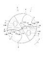
- Figure 2 is a side view of the embodiment shown in Figure 1; It is ZZ sectional drawing in FIG. It is an expanded sectional view of A part in FIG. It is an expanded side view when the margin part of embodiment shown in FIG. 1 is seen from the radial direction outer peripheral side of a drill main body in a direction perpendicular
- the drill main body 1 is formed of a hard material such as cemented carbide in a substantially cylindrical shape centering on the axis O, and a rear end portion not shown is a cylindrical shank portion as it is
- the part is a cutting edge part 2.
- Such a drill is fed to the tip side in the direction of the axis O (upper side in FIG. 2) while being rotated in the drill rotation direction T about the axis O with the shank portion held by the main shaft of the machine tool.
- the cutting material is drilled by the cutting blade 3 formed at the tip.
- the discharge groove 5 is formed in rotational symmetry with respect to the axis O.
- the cutting edge 3 is formed at the intersection ridge line portion of the wall surface 6 facing the drill rotation direction T of the chip discharge groove 5 and the end flank 4 of the drill main body 1.
- the leading end flank 4 is formed to be directed to the rear end side as it goes to the outer peripheral side of the drill main body 1, and the cutting edge 3 is given a predetermined tip angle and is directed to the opposite side to the drill rotation direction T.
- the cutting blade 3 is formed so as to face the rear end side of the drill body 1 and given a predetermined clearance angle.
- margin portion (first margin portion) 8 is formed on a cylindrical surface of the same diameter as.
- the margin portion (second margin portion) 9 is also formed in the land portion 7 at a position adjacent to the chip rotational direction T of the chip discharge groove 5 and is a double margin type drill.
- the margin portions 8 and 9 may be provided with a back taper so that the diameter gradually decreases toward the rear end side of the drill body 1.
- the wall surface 6 facing the drill rotational direction T of the chip discharge groove 5 is located on the inner peripheral side of the drill main body 1 in the cross section orthogonal to the axis O and is opposite to the drill rotational direction T as it goes to the outer peripheral side
- the first wall surface 6A having a concave curve shape extending in the drill rotation direction T after being dented in the same manner and extending from the outer periphery of the drill main body 1 to the inner peripheral side in the same cross section orthogonal to the axis O
- the second wall surface 6B has a linear shape in a cross section orthogonal to the axis O.
- the wall surface 6 further includes a thinning surface 6C which intersects the first wall surface 6A at an obtuse angle at the inner peripheral side of the drill body 1 and extends in the vicinity of the axis O in the tip flank 4.
- the extension line L1 to the outer peripheral side of the drill main body 1 of the straight line formed by the second wall 6B is the outer peripheral end of the second wall 6B and the axis O It extends toward the opposite side of the drill rotation direction T as it goes to the outer peripheral side of the drill body 1 with respect to the radial line L2 connecting the two.
- the inclination angle ⁇ of the second wall surface 6B which the extension line L1 makes with the radius line L2 is in the range of 20 ° to 40 °.
- the tangent at the outer peripheral end of the convex curve formed by the second wall 6B is the drill main body with respect to the radial line L2.
- the first wall surface 6B extends toward the opposite side to the drill rotation direction T, and the inclination angle ⁇ of the second wall 6B is an inclination angle that the tangent line makes with the radial line L2.
- the cutting wall 3 is provided with the first wall surface 6A and the tip flank 4
- the first cutting edge 3A having a concave curve shape viewed from the tip end side in the direction of the axis O in the intersection ridge line portion, and the first cutting seen from the tip end side in the direction of the axis O in the intersection ridge line portion between the second wall 6B and the tip flank 4
- the blade 3A and a convex curved or straight second cutting edge 3B intersecting the obtuse angle are formed.
- the second cutting edge 3B is linear.
- a thinning blade 3C which extends in the direction intersecting the obtuse angle with the first cutting blade 3A and reaches the vicinity of the axis O at the intersecting ridge line portion of the thinning surface 6C and the tip flank 4 Is also formed.
- first cutting edge 3A and the second cutting edge 3B of the cutting edge 3 are subjected to the honing treatment, whereby the first honing surface facing the rear end side of the drill main body 1 as going in the drill rotation direction T 11A and a second honing surface 11B are formed respectively.
- a thinning honing surface 11C is formed toward the rear end side of the drill main body 1 as it goes in the drill rotation direction T.
- the first honing surface 11A which is the honing surface of the first cutting blade 3A
- the thinning honing surface 11C which is the honing surface of the thinning blade 3C
- the second honing surface 11B which is the honing surface of the second cutting edge 3B, as shown in FIG.
- the crossing ridge line portion with the margin portion (first margin portion) 8 is formed in a convex curved shape
- the intersection ridge line portion with the first honing surface 11A is formed in a convex curve shape or a linear shape having a larger radius of curvature than the intersection ridge line portion of the margin portion 8 and the second honing surface 11B.
- the intersection ridge line portion between the first honing surface 11A and the second honing surface 11B is linear.
- the first honing surface is perpendicular to the axis O as shown in FIG.
- a straight line L3 formed by the intersection ridge line portion of the first honing surface 11A and the second honing surface 11B is the axis O
- the inclination angle ⁇ of the second honing surface 11B formed with respect to it is in the range of 13 ° to 22 °.
- the inclination angle ⁇ of the second honing surface 11B can be determined by using the straight line connecting the two ends of the convex curve as the straight line L3. Just do it.
- the hard material forming the base of the drill body 1 has a content ratio of Co of 10% by mass to 12% by mass, and has a hardness of 92.0 HRA to 93.0 HRA. It is considered to be a hard metal. Furthermore, on the surface of the cutting edge portion 2 including the inner surface of the chip discharge groove 5 of the drill main body 1 formed of such a base, a nitride mainly composed of Al and Cr, and a nitride mainly composed of Al and Ti. A hard coating film such as an object or a nitride mainly composed of Ti and Si is coated.
- first of the wall surfaces 6 facing the drill rotation direction T of the chip discharge groove 5 a cross section extending from the outer periphery of the drill main body 1 to the inner peripheral side and intersecting the first wall 6A with an obtuse angle
- the convexly curved or straight second wall surface 6B is, in a cross section orthogonal to the axis O, a tangent to the outer peripheral end of the convex curve formed by the second wall 6B or a straight line outer peripheral side of the second wall 6B formed.
- the extension line L1 of the second wall 6B extends in the direction opposite to the drill rotation direction T as it goes to the outer peripheral side of the drill body 1 with respect to the radial line L2 connecting the outer peripheral end of the second wall 6B and the axis O . For this reason, the crossing angle between the second wall surface 6B and the margin portion (first margin portion) 8 can be set to an obtuse angle.
- the strength of the intersecting ridge line portion between the second wall surface 6B which is the rake surface on the outer peripheral side of the drill body 1 and the margin portion 8 can be secured, and the margin wear can be suppressed.
- the first wall surface 6A having a concave shape in cross section intersects with the second wall surface 6B having a convex surface shape or a linear shape in an obtuse angle, the first wall surface 6A functions as a chip breaker to curl chips small. As a result, it is possible to prevent chips from flowing out from the second wall 6B toward the margin portion 8 and to further suppress the margin wear.
- a first honing surface 11A and a second honing surface 11B are provided on the first cutting edge 3A and the second cutting edge 3B, respectively, toward the rear end side of the drill main body 1 in the drill rotation direction T.
- the entire ridgeline portion of the margin portion 8 and the second honing surface 11B is formed in a convex curve shape. It is done.
- the strength of the second cutting edge 3B can be secured at the outer peripheral end of the cutting body 3 of the drill main body 1 as well, and the second honing surface 11B, its end flank 4 (first end flank 4A) or margin portion It is possible to prevent micro chipping from occurring at the ridge line portion with 8 and expanding. For this reason, it is possible to suppress flank wear and margin wear due to such minute chipping.
- the intersection ridgeline portion between the second honing surface 11B and the first honing surface 11A which is the honing surface of the first cutting edge 3A has a curvature more than the intersection ridgeline portion between the margin 8 and the second honing surface 11B. Since it is formed in the shape of a convex curve with a large radius or in a straight line, a sharp sharpness can be maintained at the inner peripheral side of the drill body 1 of the second cutting edge 3B and the first cutting edge 3A. For this reason, it can prevent that cutting resistance increases as the whole cutting blade 3, and it becomes possible to prevent the situation where the drill main body 1 is broken by excessive cutting resistance.
- the intersecting ridge line portion of the first honing surface 11A and the second honing surface 11B is formed.
- the inclination angle ⁇ of the second honing surface 11B, which the straight line makes with the axis O, is in the range of 13 ° to 22 °, and in the cross section orthogonal to the axis O, the drill body 1 outer periphery of the straight line formed by the second wall 6B.
- the inclination angle ⁇ of the second wall 6B is in the range of 20 ° to 40 ° with respect to the radial line L2 where the extension line L1 to the side connects the axis O with the outer peripheral end of the second wall 6B. While effectively preventing the wear from being promoted, it is also possible to more reliably prevent an increase in cutting resistance.
- the coating film is coated as in the above, the coating film is likely to be broken, which may accelerate flank wear and margin wear at a stretch.
- the inclination angle ⁇ is more preferably in the range of 15 ° to 20 °.
- the crossing angle between the first wall 6A and the second wall 6B in the cross section orthogonal to the axis O becomes small, and the above-mentioned chips from the first wall 6A The function as a breaker is lost, and chips flow from the second wall surface 6B toward the margin portion 8 to contact the intersection ridge line portion of the second wall surface 6B and the margin portion 8, and the second in the intersection ridge line portion
- margin wear is also promoted.
- the inclination angle ⁇ of the second wall surface 6B is larger than 40 °, the cutting quality of the second cutting edge 3B formed at the intersection ridge line portion between the second wall surface 6B and the tip flank 4 is lost and the flank is Along with the increase of the wear, the margin wear of the tip of the drill body 1 may be increased.
- the inclination angle ⁇ is more preferably in the range of 30 ° to 40 °.
- the base material of the drill body 1 is a WC-Co-based cemented carbide having a Co content ratio of 10% by mass to 12% by mass and a hardness of 92.0 HRA to 93.0 HRA. It is possible to obtain a drill in which the toughness and the wear resistance are balanced at a high level. That is, when the hardness of the base material of the drill main body 1 is less than 92.0 HRA, the wear resistance may be impaired, whereas when it exceeds 93.0 HRA, the toughness may be impaired and breakage may easily occur.
- the content ratio of Co is less than 10% by mass, the toughness decreases and the possibility of breakage increases, and conversely, if the content ratio of Co is more than 12% by mass, the hardness of the substrate decreases and the abrasion resistance There is a risk that the sex may decline.
- the convex curve formed by the intersection ridge line portion of the margin portion 8 and the second honing surface 11B has a curvature radius that is perpendicular to the axis O and viewed from the outer peripheral side of the drill main body 1 facing the margin portion 8
- the diameter D (mm) of the cutting blade 3, that is, the diameter of a circle formed by the outer peripheral end of the cutting blade 3 around the axis O, is desirably D ⁇ 3 to D ⁇ 15 (where the unit is ⁇ m).
- the diameter D of the cutting edge 3 is 6 mm
- the length of the cutting edge 2 is 30 mm
- the inclination angle ⁇ of the second honing surface 11B is in the range of 13 ° to 22 °
- the convex curve formed by the intersection of the margin 8 and the second honing surface 11B with the inclination angle ⁇ of the second wall 6B in the range of 20 ° to 40 ° is made to face the margin 8 perpendicularly to the axis O Twelve drills were manufactured in which the radius of curvature R when viewed from the outer peripheral side of the main body 1 was changed by D ⁇ 3 to D ⁇ 15 (18 ⁇ m to 90 ⁇ m) with respect to the diameter D (6 mm) of the cutting edge 3 .
- the inclination angle ⁇ of the second honing surface 11B, the inclination angle ⁇ of the second wall surface 6B, and the crossing ridge line portion between the margin 8 and the second honing surface 11B are formed.
- At least one of the curvature radius R of the convex curve is manufactured in 11 types of drills having the same shape and dimensions as those of Examples 1 to 12 outside the range of the above embodiment, and drilling is performed under the same conditions as the embodiment.
- the flank wear and margin wear were evaluated. These results are shown in Table 2 as Comparative Examples 1 to 11.
- the base material A of the drill main body 1 is a WC-Co-based cemented carbide with a content ratio of Co of 11% by mass and a hardness of 91.5 HRA, and the base material B has a content ratio of Co of 11% by mass and hardness 92.5 HRA WC-Co base cemented carbide.
- high hardness TiSiN is formed on a laminated film in which AlCrSiN and AlTiN are alternately laminated in a film thickness of 10 nm or less. The coating film of the provided film structure is coated.
- flank wear evaluation of flank wear is shown in FIG. 6 by using double circles for those with an abrasion width of less than 100 ⁇ m, circles for those with 100 ⁇ m to 110 ⁇ m or less, and triangles with an abrasion width exceeding 110 ⁇ m.
- the cutting blade 3 etc. had a defect, it was marked with a cross.
- margin wear as shown in FIG. 7A, the case of normal wear is indicated by a double circle, and as shown in FIG. 7B, a linear shallow scratch is indicated by a circle and indicated by FIG. 7C.
- FIG. 7D when there is one linear deep scratch, a triangular mark is used, and as shown in FIG. 7D, two linear deep flaws are used as cross.
- the entire cutting edge maintains sharp sharpness to prevent breakage and the like of the drill body due to an increase in cutting resistance, while cutting at the outer peripheral end of the second cutting edge which is the cutting blade on the outer peripheral side of the drill body
- the blade strength can be secured to prevent the occurrence of minute chipping on the second honing surface. For this reason, it is possible to suppress the occurrence of large flank wear and margin wear on the tip flank and the margin from such a minute chipping.
Landscapes
- Engineering & Computer Science (AREA)
- Mechanical Engineering (AREA)
- Drilling Tools (AREA)
Abstract
Description
本願は、2017年12月26日に、日本に出願された特願2017-249825号に基づき優先権を主張し、その内容をここに援用する。


2 切刃部
3 切刃
3A 第1切刃
3B 第2切刃
4 先端逃げ面
5 切屑排出溝
6 切屑排出溝5のドリル回転方向Tを向く壁面
6A 第1壁面
6B 第2壁面
7 ランド部
8 マージン部(第1マージン部)
11A 第1ホーニング面
11B 第2ホーニング面
O ドリル本体1の軸線
T ドリル回転方向
L1 軸線Oに直交する断面において第2壁面6Bがなす直線のドリル本体1外周側へ
の延長線
L2 第2壁面6Bの外周端と軸線Oとを結ぶ半径線
L3 マージン部8を軸線Oに垂直な方向でドリル本体1の径方向外周側から見たとき
に、第1ホーニング面11Aと第2ホーニング面11Bとの交差稜線部がなす直線
α 第2ホーニング面の傾き角
θ 第2壁面の傾斜角
Claims (4)
- 軸線回りに回転されるドリル本体の先端部外周に切屑排出溝を備え、この切屑排出溝のドリル回転方向を向く壁面と上記ドリル本体の先端逃げ面との交差稜線部に切刃が形成されたドリルであって、
上記切屑排出溝の間の上記ドリル本体外周のランド部に、該切屑排出溝のドリル回転方向とは反対側に隣接するマージン部を有し、
上記切屑排出溝のドリル回転方向を向く壁面は、上記軸線に直交する断面において上記ドリル本体の内周側に位置して外周側に向かうに従いドリル回転方向とは反対側に凹んでからドリル回転方向に延びる凹曲線状をなす第1壁面と、上記軸線に直交する断面において上記ドリル本体の外周から内周側に向けて延びて上記第1壁面と鈍角に交差する凸曲線状または直線状をなす第2壁面とを備え、
上記軸線に直交する断面において、上記第2壁面がなす凸曲線の外周端における接線、または該第2壁面がなす直線の上記ドリル本体外周側への延長線は、この第2壁面の外周端と上記軸線とを結ぶ半径線に対して上記ドリル本体外周側に向かうに従いドリル回転方向とは反対側に向かうように延びており、
上記切刃は、上記第1壁面と上記先端逃げ面との交差稜線部に形成される凹曲線状の第1切刃と、上記第2壁面と上記先端逃げ面との交差稜線部に形成されて上記第1切刃と鈍角に交差する凸曲線状または直線状の第2切刃とを備え、
上記第1切刃と上記第2切刃には、ドリル回転方向に向かうに従い上記ドリル本体の後端側に向かう第1ホーニング面と第2ホーニング面とがそれぞれ設けられていて、
上記マージン部を上記軸線に垂直な方向で上記ドリル本体の径方向外周側から見たときに、上記マージン部と上記第2切刃のホーニング面である上記第2ホーニング面との交差稜線部は全体が凸曲線状に形成されているとともに、この第2ホーニング面と上記第1切刃のホーニング面である上記第1ホーニング面との交差稜線部は、上記マージン部と上記第2ホーニング面との交差稜線部よりも曲率半径の大きな凸曲線状、または直線状に形成されていることを特徴とするドリル。 - 上記マージン部を上記軸線に垂直な方向で上記ドリル本体の径方向外周側から見たときに、上記第1ホーニング面と上記第2ホーニング面との交差稜線部がなす凸曲線の両端を結ぶ直線、または上記第1ホーニング面と上記第2ホーニング面との交差稜線部がなす直線が上記軸線に対してなす上記第2ホーニング面の傾き角が13°~22°の範囲であるとともに、
上記軸線に直交する断面において、上記第2壁面がなす凸曲線の外周端における接線または該第2壁面がなす直線の上記ドリル本体外周側への延長線が上記半径線に対してなす上記第2壁面の傾斜角が20°~40°の範囲であることを特徴とする請求項1に記載のドリル。 - 上記ドリル本体の基材は、Coの含有比率が10質量%~12質量%であって、硬度が92.0HRA~93.0HRAのWC-Co基超硬合金であることを特徴とする請求項1または請求項2に記載のドリル。
- 上記マージン部と上記第2ホーニング面との交差稜線部がなす上記凸曲線は、上記軸線に垂直に上記マージン部に対向して上記ドリル本体の外周側から見たときに、該凸曲線の曲率半径が、上記切刃の外周端が上記軸線回りになす円の直径D(mm)に対して、D×3~D×15(μm)であることを特徴とする請求項1から請求項3のうちいずれか一項に記載のドリル。
Priority Applications (5)
| Application Number | Priority Date | Filing Date | Title |
|---|---|---|---|
| JP2019562978A JP7206496B2 (ja) | 2017-12-26 | 2018-12-13 | ドリル |
| CN201880083186.8A CN111587160B (zh) | 2017-12-26 | 2018-12-13 | 钻头 |
| US16/957,213 US11364557B2 (en) | 2017-12-26 | 2018-12-13 | Drill |
| KR1020207020781A KR102399372B1 (ko) | 2017-12-26 | 2018-12-13 | 드릴 |
| EP18894227.0A EP3733334A4 (en) | 2017-12-26 | 2018-12-13 | FOREST |
Applications Claiming Priority (2)
| Application Number | Priority Date | Filing Date | Title |
|---|---|---|---|
| JP2017249825 | 2017-12-26 | ||
| JP2017-249825 | 2017-12-26 |
Publications (1)
| Publication Number | Publication Date |
|---|---|
| WO2019131177A1 true WO2019131177A1 (ja) | 2019-07-04 |
Family
ID=67067257
Family Applications (1)
| Application Number | Title | Priority Date | Filing Date |
|---|---|---|---|
| PCT/JP2018/045904 WO2019131177A1 (ja) | 2017-12-26 | 2018-12-13 | ドリル |
Country Status (6)
| Country | Link |
|---|---|
| US (1) | US11364557B2 (ja) |
| EP (1) | EP3733334A4 (ja) |
| JP (1) | JP7206496B2 (ja) |
| KR (1) | KR102399372B1 (ja) |
| CN (1) | CN111587160B (ja) |
| WO (1) | WO2019131177A1 (ja) |
Cited By (1)
| Publication number | Priority date | Publication date | Assignee | Title |
|---|---|---|---|---|
| WO2024176439A1 (ja) * | 2023-02-24 | 2024-08-29 | 三菱マテリアル株式会社 | ドリル |
Families Citing this family (2)
| Publication number | Priority date | Publication date | Assignee | Title |
|---|---|---|---|---|
| DE102019211827B4 (de) * | 2019-08-07 | 2023-10-19 | Kennametal Inc. | Bohrer und Verfahren zur Herstellung eines Bohrers |
| KR102544883B1 (ko) | 2021-09-17 | 2023-06-21 | 한국야금 주식회사 | 드릴 |
Citations (7)
| Publication number | Priority date | Publication date | Assignee | Title |
|---|---|---|---|---|
| WO2006079317A1 (de) * | 2005-01-25 | 2006-08-03 | Firma Gühring Ohg | Variabler schneidkantenabzug für bohrwerkzeuge |
| JP2014008549A (ja) * | 2012-06-28 | 2014-01-20 | Sumitomo Electric Hardmetal Corp | ドリル |
| JP2015093351A (ja) * | 2013-11-12 | 2015-05-18 | 三菱マテリアル株式会社 | ドリル |
| JP5762547B2 (ja) | 2011-09-06 | 2015-08-12 | オーエスジー株式会社 | ドリル |
| JP2016002617A (ja) * | 2014-06-17 | 2016-01-12 | 住友電工ハードメタル株式会社 | ドリル |
| WO2016043098A1 (ja) | 2014-09-19 | 2016-03-24 | 住友電工ハードメタル株式会社 | ドリル |
| JP2017124475A (ja) * | 2016-01-15 | 2017-07-20 | 三菱日立ツール株式会社 | ドリル |
Family Cites Families (7)
| Publication number | Priority date | Publication date | Assignee | Title |
|---|---|---|---|---|
| US6585460B1 (en) * | 2000-11-13 | 2003-07-01 | General Electric Company | Drill having machine grindable cutting edge |
| JP4120187B2 (ja) * | 2001-07-10 | 2008-07-16 | 三菱マテリアル株式会社 | ドリル |
| CN103906592B (zh) * | 2011-11-04 | 2016-03-16 | Osg株式会社 | 钻头 |
| JP5974695B2 (ja) * | 2012-07-13 | 2016-08-23 | 三菱日立ツール株式会社 | ドリル及びドリルの刃先部の製造方法 |
| JP2017087406A (ja) * | 2015-11-17 | 2017-05-25 | 三菱日立ツール株式会社 | ドリル |
| KR102514163B1 (ko) * | 2016-04-15 | 2023-03-24 | 산드빅 인터렉츄얼 프로퍼티 에이비 | 서멧 또는 초경 합금의 3 차원 인쇄 |
| JP7078825B2 (ja) * | 2017-07-27 | 2022-06-01 | 住友電工ハードメタル株式会社 | ドリル |
-
2018
- 2018-12-13 JP JP2019562978A patent/JP7206496B2/ja active Active
- 2018-12-13 EP EP18894227.0A patent/EP3733334A4/en active Pending
- 2018-12-13 US US16/957,213 patent/US11364557B2/en active Active
- 2018-12-13 KR KR1020207020781A patent/KR102399372B1/ko active IP Right Grant
- 2018-12-13 WO PCT/JP2018/045904 patent/WO2019131177A1/ja unknown
- 2018-12-13 CN CN201880083186.8A patent/CN111587160B/zh active Active
Patent Citations (7)
| Publication number | Priority date | Publication date | Assignee | Title |
|---|---|---|---|---|
| WO2006079317A1 (de) * | 2005-01-25 | 2006-08-03 | Firma Gühring Ohg | Variabler schneidkantenabzug für bohrwerkzeuge |
| JP5762547B2 (ja) | 2011-09-06 | 2015-08-12 | オーエスジー株式会社 | ドリル |
| JP2014008549A (ja) * | 2012-06-28 | 2014-01-20 | Sumitomo Electric Hardmetal Corp | ドリル |
| JP2015093351A (ja) * | 2013-11-12 | 2015-05-18 | 三菱マテリアル株式会社 | ドリル |
| JP2016002617A (ja) * | 2014-06-17 | 2016-01-12 | 住友電工ハードメタル株式会社 | ドリル |
| WO2016043098A1 (ja) | 2014-09-19 | 2016-03-24 | 住友電工ハードメタル株式会社 | ドリル |
| JP2017124475A (ja) * | 2016-01-15 | 2017-07-20 | 三菱日立ツール株式会社 | ドリル |
Cited By (1)
| Publication number | Priority date | Publication date | Assignee | Title |
|---|---|---|---|---|
| WO2024176439A1 (ja) * | 2023-02-24 | 2024-08-29 | 三菱マテリアル株式会社 | ドリル |
Also Published As
| Publication number | Publication date |
|---|---|
| CN111587160B (zh) | 2023-04-14 |
| KR102399372B1 (ko) | 2022-05-17 |
| US11364557B2 (en) | 2022-06-21 |
| KR20200096983A (ko) | 2020-08-14 |
| US20200398350A1 (en) | 2020-12-24 |
| JP7206496B2 (ja) | 2023-01-18 |
| CN111587160A (zh) | 2020-08-25 |
| JPWO2019131177A1 (ja) | 2020-12-17 |
| EP3733334A1 (en) | 2020-11-04 |
| EP3733334A4 (en) | 2021-09-22 |
Similar Documents
| Publication | Publication Date | Title |
|---|---|---|
| US9511424B2 (en) | Drill | |
| JP5816364B2 (ja) | 3枚刃ドリル | |
| US9492877B2 (en) | Drill | |
| WO2017179689A1 (ja) | 小径ドリル | |
| JP4975395B2 (ja) | ボールエンドミル | |
| JP6268716B2 (ja) | ドリル | |
| US20020044843A1 (en) | Hole forming tool | |
| WO2019131177A1 (ja) | ドリル | |
| JP6828824B2 (ja) | 小径ドリルおよび小径ドリルの製造方法 | |
| WO2010086988A1 (ja) | ダブルアングルドリル | |
| JPWO2019188135A1 (ja) | エンドミル本体及びエンドミル | |
| JP6848176B2 (ja) | ドリル | |
| JP2012236242A (ja) | エンドミル | |
| JP2007007809A (ja) | 低加工硬化超硬ドリル | |
| JP6604437B2 (ja) | 切削インサート及び刃先交換式回転切削工具 | |
| JP2008142834A (ja) | ドリル | |
| JP2013022663A (ja) | ドリル | |
| JP2018176360A (ja) | 回転切削式穴あけ工具 | |
| JP2014193513A (ja) | ドリル | |
| JP6825400B2 (ja) | テーパボールエンドミル | |
| WO2012053090A1 (ja) | 3枚刃ドリル | |
| JP4053295B2 (ja) | 穴明け工具 | |
| JP2016147328A (ja) | ドリル | |
| JP2007007808A (ja) | 低加工硬化超硬ドリル | |
| JP2002301613A (ja) | ダイヤモンド焼結体付ドリル |
Legal Events
| Date | Code | Title | Description |
|---|---|---|---|
| 121 | Ep: the epo has been informed by wipo that ep was designated in this application |
Ref document number: 18894227 Country of ref document: EP Kind code of ref document: A1 |
|
| ENP | Entry into the national phase |
Ref document number: 2019562978 Country of ref document: JP Kind code of ref document: A |
|
| NENP | Non-entry into the national phase |
Ref country code: DE |
|
| ENP | Entry into the national phase |
Ref document number: 20207020781 Country of ref document: KR Kind code of ref document: A |
|
| ENP | Entry into the national phase |
Ref document number: 2018894227 Country of ref document: EP Effective date: 20200727 |