WO2019130737A1 - 電磁アクチュエータ - Google Patents
電磁アクチュエータ Download PDFInfo
- Publication number
- WO2019130737A1 WO2019130737A1 PCT/JP2018/038486 JP2018038486W WO2019130737A1 WO 2019130737 A1 WO2019130737 A1 WO 2019130737A1 JP 2018038486 W JP2018038486 W JP 2018038486W WO 2019130737 A1 WO2019130737 A1 WO 2019130737A1
- Authority
- WO
- WIPO (PCT)
- Prior art keywords
- predetermined
- valve body
- predetermined direction
- damper
- movable member
- Prior art date
- Legal status (The legal status is an assumption and is not a legal conclusion. Google has not performed a legal analysis and makes no representation as to the accuracy of the status listed.)
- Ceased
Links
Images








Classifications
-
- F—MECHANICAL ENGINEERING; LIGHTING; HEATING; WEAPONS; BLASTING
- F16—ENGINEERING ELEMENTS AND UNITS; GENERAL MEASURES FOR PRODUCING AND MAINTAINING EFFECTIVE FUNCTIONING OF MACHINES OR INSTALLATIONS; THERMAL INSULATION IN GENERAL
- F16K—VALVES; TAPS; COCKS; ACTUATING-FLOATS; DEVICES FOR VENTING OR AERATING
- F16K31/00—Actuating devices; Operating means; Releasing devices
- F16K31/02—Actuating devices; Operating means; Releasing devices electric; magnetic
- F16K31/06—Actuating devices; Operating means; Releasing devices electric; magnetic using a magnet, e.g. diaphragm valves, cutting off by means of a liquid
- F16K31/0675—Electromagnet aspects, e.g. electric supply therefor
-
- F—MECHANICAL ENGINEERING; LIGHTING; HEATING; WEAPONS; BLASTING
- F16—ENGINEERING ELEMENTS AND UNITS; GENERAL MEASURES FOR PRODUCING AND MAINTAINING EFFECTIVE FUNCTIONING OF MACHINES OR INSTALLATIONS; THERMAL INSULATION IN GENERAL
- F16K—VALVES; TAPS; COCKS; ACTUATING-FLOATS; DEVICES FOR VENTING OR AERATING
- F16K17/00—Safety valves; Equalising valves, e.g. pressure relief valves
- F16K17/02—Safety valves; Equalising valves, e.g. pressure relief valves opening on surplus pressure on one side; closing on insufficient pressure on one side
- F16K17/04—Safety valves; Equalising valves, e.g. pressure relief valves opening on surplus pressure on one side; closing on insufficient pressure on one side spring-loaded
- F16K17/0433—Safety valves; Equalising valves, e.g. pressure relief valves opening on surplus pressure on one side; closing on insufficient pressure on one side spring-loaded with vibration preventing means
-
- F—MECHANICAL ENGINEERING; LIGHTING; HEATING; WEAPONS; BLASTING
- F16—ENGINEERING ELEMENTS AND UNITS; GENERAL MEASURES FOR PRODUCING AND MAINTAINING EFFECTIVE FUNCTIONING OF MACHINES OR INSTALLATIONS; THERMAL INSULATION IN GENERAL
- F16K—VALVES; TAPS; COCKS; ACTUATING-FLOATS; DEVICES FOR VENTING OR AERATING
- F16K3/00—Gate valves or sliding valves, i.e. cut-off apparatus with closing members having a sliding movement along the seat for opening and closing
- F16K3/02—Gate valves or sliding valves, i.e. cut-off apparatus with closing members having a sliding movement along the seat for opening and closing with flat sealing faces; Packings therefor
- F16K3/0254—Gate valves or sliding valves, i.e. cut-off apparatus with closing members having a sliding movement along the seat for opening and closing with flat sealing faces; Packings therefor being operated by particular means
-
- F—MECHANICAL ENGINEERING; LIGHTING; HEATING; WEAPONS; BLASTING
- F16—ENGINEERING ELEMENTS AND UNITS; GENERAL MEASURES FOR PRODUCING AND MAINTAINING EFFECTIVE FUNCTIONING OF MACHINES OR INSTALLATIONS; THERMAL INSULATION IN GENERAL
- F16K—VALVES; TAPS; COCKS; ACTUATING-FLOATS; DEVICES FOR VENTING OR AERATING
- F16K3/00—Gate valves or sliding valves, i.e. cut-off apparatus with closing members having a sliding movement along the seat for opening and closing
- F16K3/22—Gate valves or sliding valves, i.e. cut-off apparatus with closing members having a sliding movement along the seat for opening and closing with sealing faces shaped as surfaces of solids of revolution
- F16K3/24—Gate valves or sliding valves, i.e. cut-off apparatus with closing members having a sliding movement along the seat for opening and closing with sealing faces shaped as surfaces of solids of revolution with cylindrical valve members
- F16K3/26—Gate valves or sliding valves, i.e. cut-off apparatus with closing members having a sliding movement along the seat for opening and closing with sealing faces shaped as surfaces of solids of revolution with cylindrical valve members with fluid passages in the valve member
-
- F—MECHANICAL ENGINEERING; LIGHTING; HEATING; WEAPONS; BLASTING
- F16—ENGINEERING ELEMENTS AND UNITS; GENERAL MEASURES FOR PRODUCING AND MAINTAINING EFFECTIVE FUNCTIONING OF MACHINES OR INSTALLATIONS; THERMAL INSULATION IN GENERAL
- F16K—VALVES; TAPS; COCKS; ACTUATING-FLOATS; DEVICES FOR VENTING OR AERATING
- F16K31/00—Actuating devices; Operating means; Releasing devices
- F16K31/02—Actuating devices; Operating means; Releasing devices electric; magnetic
- F16K31/06—Actuating devices; Operating means; Releasing devices electric; magnetic using a magnet, e.g. diaphragm valves, cutting off by means of a liquid
- F16K31/0603—Multiple-way valves
- F16K31/061—Sliding valves
- F16K31/0617—Sliding valves with flat slides
-
- F—MECHANICAL ENGINEERING; LIGHTING; HEATING; WEAPONS; BLASTING
- F16—ENGINEERING ELEMENTS AND UNITS; GENERAL MEASURES FOR PRODUCING AND MAINTAINING EFFECTIVE FUNCTIONING OF MACHINES OR INSTALLATIONS; THERMAL INSULATION IN GENERAL
- F16K—VALVES; TAPS; COCKS; ACTUATING-FLOATS; DEVICES FOR VENTING OR AERATING
- F16K47/00—Means in valves for absorbing fluid energy
- F16K47/02—Means in valves for absorbing fluid energy for preventing water-hammer or noise
- F16K47/023—Means in valves for absorbing fluid energy for preventing water-hammer or noise for preventing water-hammer, e.g. damping of the valve movement
-
- F—MECHANICAL ENGINEERING; LIGHTING; HEATING; WEAPONS; BLASTING
- F16—ENGINEERING ELEMENTS AND UNITS; GENERAL MEASURES FOR PRODUCING AND MAINTAINING EFFECTIVE FUNCTIONING OF MACHINES OR INSTALLATIONS; THERMAL INSULATION IN GENERAL
- F16K—VALVES; TAPS; COCKS; ACTUATING-FLOATS; DEVICES FOR VENTING OR AERATING
- F16K31/00—Actuating devices; Operating means; Releasing devices
- F16K31/02—Actuating devices; Operating means; Releasing devices electric; magnetic
- F16K31/06—Actuating devices; Operating means; Releasing devices electric; magnetic using a magnet, e.g. diaphragm valves, cutting off by means of a liquid
Definitions
- the present disclosure relates to an electromagnetic actuator that drives a movable member by an electromagnetic force.
- both ends of the valve body are supported by plate springs so that a gap is formed between the valve body (movable member) and the main body, and the valve body is noncontacted by an electromagnetic force.
- a flow path switching valve that is driven to reciprocate at the same time (see Patent Document 1).
- the valve body can be reciprocately driven in a state in which the valve body and the main body do not rub each other, so that responsiveness of switching the flow path can be improved.
- the present disclosure has been made to solve these problems, and its main object is to provide an electromagnetic actuator capable of suppressing the vibration of the movable member while improving the response for driving the movable member. It is in.
- a first means for solving the above problems is an electromagnetic actuator, and A pair of leaf springs which apply an elastic force corresponding to the amount of deformation in a predetermined direction; A movable member movably supported in the predetermined direction by the pair of leaf springs; A driving unit configured to drive the movable member in the predetermined direction in a noncontact manner by an electromagnetic force applied between the pair of leaf springs in the predetermined direction; A container in which the plate spring and the movable member are accommodated; A damper which is attached to the movable member to form a predetermined space partitioned by the inner surface of the container, and which has a predetermined gap for communicating the inside and the outside of the predetermined space in the predetermined direction with the inner surface , Equipped with
- the elastic force corresponding to the amount of deformation of the plate spring is applied in a predetermined direction by the pair of plate springs.
- the movable member is supported movably in the predetermined direction by the pair of leaf springs, so that the movable member can be movably supported in a non-sliding manner.
- the movable member is driven in a predetermined direction in a noncontact manner by the electromagnetic force exerted by the drive unit.
- the movable member is supported by a pair of leaf springs, and an electromagnetic force is exerted between the pair of leaf springs in the predetermined direction. For this reason, it can suppress that a movable member shakes at the time of being driven.
- the leaf spring and the movable member are housed inside the container.
- the damper is attached to the movable member, and a predetermined space defined by the inner surface of the container and the damper is formed. Then, a predetermined gap for communicating the inside and the outside of the predetermined space in the predetermined direction is formed between the inner surface of the container and the damper. For this reason, when the damper is driven in the predetermined direction together with the movable member, the fluid flows in and out of the predetermined space through the predetermined gap. Therefore, due to the resistance when the fluid passes through the predetermined gap, a damping force that attenuates the vibration of the movable member can be applied, and the vibration of the movable member can be suppressed. Furthermore, since the vibration of the movable member can be damped without sliding of the movable member with another member, it is possible to suppress the decrease in responsiveness of the movable member.
- the movable member is a valve body having an open channel which opens in a predetermined length in a predetermined direction on a predetermined surface, and a plurality of ports open on opposite surfaces facing the predetermined surface And a main body formed in parallel at intervals shorter than the predetermined length in the predetermined direction and in which connection channels respectively connected to the plurality of ports are formed, and the container accommodates the main body inside ing.
- the fluid can be made to flow into and out of each port connected to each connection channel through the connection channel formed in the main body.
- the valve body is formed with an open channel which opens at a predetermined length in a predetermined direction on a predetermined surface.
- a plurality of ports opened in an opposing surface facing the predetermined surface are formed side by side at intervals shorter than the predetermined length in the predetermined direction. Therefore, by driving the valve in the predetermined direction by the drive unit, it is possible to control the state in which the plurality of ports are connected via the open flow path of the valve, that is, the flow state of the fluid.
- plate spring and the valve body (movable member) inside has accommodated the main body inside.
- the fluid which flowed in from the above-mentioned port to the circumference of the valve body flows inside the container, and flows in and out of the above-mentioned predetermined space through the above-mentioned predetermined gap. Therefore, the fluid whose flow state is to be controlled by the valve body can be used as the fluid for damping the vibration of the movable member, and it is not necessary to separately prepare the fluid dedicated to the damper.
- the damper is attached to the movable member outside the plate spring in the predetermined direction. For this reason, compared with the configuration in which the damper is attached to the movable member on the inner side relative to the movable member in the predetermined direction, the predetermined space partitioned by the inner surface of the container and the damper can be easily reduced, and the predetermined space is facilitated. Can be formed.
- the damper is formed in a plate shape, and the predetermined gap is formed annularly between the inner surface and the outer peripheral surface of the damper.
- the damper is formed in a plate shape, the shape of the damper can be simplified and the space for arranging the damper can be reduced.
- the predetermined gap is annularly formed between the inner surface of the container and the outer peripheral surface of the damper. For this reason, it can suppress that the resistance of a fluid acts on a part of damper uniformly, and it becomes easy to stabilize the attitude
- the damper is fixed to the movable member such that the principal surface having the largest area is perpendicular to the predetermined direction. For this reason, when the damper is driven in a predetermined direction together with the movable member, the fluid can be applied vertically to the damper, so that the damper can be suppressed from tilting and, consequently, the movable member can be inclined.
- the size of the predetermined gap is kept constant by the drive unit. For this reason, when the movable member is driven, it is possible to suppress a change in the flow of fluid passing through the predetermined gap, and it becomes easy to stabilize the attitude of the damper and, in turn, the attitude of the movable member.
- the predetermined space is formed at the end of the container in the predetermined direction. Therefore, in the electromagnetic actuator, a predetermined space can be easily secured, and interference between the other components and the damper can be easily suppressed.
- a configuration may be employed in which the size of the predetermined gap is 0.2 to 5 mm. According to such a configuration, an appropriate damping force can be applied to the driven movable member, and it is possible to suppress a decrease in responsiveness of the movable member while attenuating the vibration of the movable member.
- the size of the predetermined gap may be changed according to the type and characteristics of the fluid.
- a ninth means is an electromagnetic actuator, A pair of leaf springs which apply an elastic force corresponding to the amount of deformation in a predetermined direction; A valve body which is supported movably in the predetermined direction by the pair of leaf springs and controls the flow state of the liquid; A driving unit that drives the valve in a noncontact manner in the predetermined direction by an electromagnetic force applied between the pair of leaf springs in the predetermined direction; A container in which the plate spring and the valve body are housed; A damper attached to the valve body to form a predetermined gap with the inner surface of the container, and allowing the liquid to pass through the predetermined gap in the predetermined direction; Equipped with
- the flow state of the liquid is controlled by the valve body.
- a damper is attached to the valve body, and a predetermined gap is formed between the inner surface of the container and the damper. Then, the damper causes the liquid to pass through the predetermined gap in the predetermined direction. For this reason, when the damper is driven in a predetermined direction together with the valve body, a damping force that damps the vibration of the valve body can be applied by the resistance when the liquid passes through the predetermined gap, and the vibration of the valve body is suppressed. can do. Furthermore, since the vibration of the valve body can be damped without sliding of the valve body with other members, it is possible to suppress a decrease in responsiveness of the valve body. Moreover, since the liquid whose flow state is to be controlled by the valve body is used as the liquid for damping the vibration of the valve body, it is not necessary to separately prepare a liquid dedicated to the damper.
- the valve body is formed with an open flow passage opening in a predetermined length in a predetermined direction on a predetermined surface, and a plurality of ports opened in an opposing surface facing the predetermined surface It comprises a main body which is formed in a predetermined direction at intervals shorter than the predetermined length and in which connection channels respectively connected to the plurality of ports are formed, and the container accommodates the main body inside. According to such a configuration, the same function and effect as those of the second means can be achieved.
- the damper in the predetermined direction, is attached to the valve body outside the plate spring. According to such a configuration, the same function and effect as those of the third means can be obtained.
- a twelfth means comprises a positioning pin for restricting rotation of the damper along a plane perpendicular to the predetermined direction.
- the positioning pin restricts rotation of the damper along a plane perpendicular to the predetermined direction. For this reason, it is possible to reliably prevent the predetermined gap from changing due to the rotation of the damper, and it is possible to suppress the disturbance of the attitude of the damper and hence the attitude of the movable member.
- the perspective sectional view which shows a flow ratio control valve The perspective view which shows the port periphery of a valve mechanism.
- FIG. The perspective view which shows the state which removed one port and the 1st main body from FIG.
- Front view sectional drawing which shows the valve mechanism of a non-excitation state.
- Front view sectional drawing which shows the valve mechanism of the excitation state of positive direction.
- the graph which shows the relationship between a drive current, a flow, and a vibration generation range.
- the time chart which shows B port pressure of the flow ratio control valve of a comparative example.
- the time chart which shows B port pressure of the flow ratio control valve of this embodiment.
- the perspective sectional view which shows the example of a change of a valve mechanism.
- the graph which shows an example of the relation between drive current and a flow.
- the graph which shows the example of a change of the relation between drive current and a flow.
- the graph which shows the other example of a change of the relation between drive current and flow.
- the flow ratio control valve 10 (corresponding to an electromagnetic actuator) includes a valve mechanism 20 and a drive unit 70.
- the valve mechanism 20 and the drive unit 70 are connected via the connection member 24.
- the drive unit 70 drives the valve body 31 (see FIG. 4) of the valve mechanism 20.
- the valve mechanism 20 includes a housing 21, a valve body 31, a first main body 41A (main body), a second main body 41B, a plate spring 51, a lid 27, and the like.
- the housing 21, the valve body 31, the first main body 41A, the second main body 41B, the plate spring 51, and the lid 27 are formed of nonmagnetic material.
- FIG. 2 shows a state in which the drive unit 70 is removed from the flow ratio control valve 10 of FIG.
- the housing 21 is formed in a square tubular shape (consisting of a plurality of parts).
- the housing 21 is provided with a C0 port (common port) for inputting a refrigerant (corresponding to a fluid), an A0 port (first output port) for outputting a refrigerant, and a B0 port (second output port) for outputting a refrigerant.
- the C0 port, the A0 port, and the B0 port are formed of nonmagnetic material.
- An input channel, a first output channel, and a second output channel are connected to the C0 port, the A0 port, and the B0 port, respectively.
- the input flow passage opens at the inner surface of the housing 21.
- the first output flow passage and the second output flow passage are connected to the first main body 41A.
- FIG. 3 shows the valve mechanism 20 of FIG. 2 with the housing 21 and the lid 27 removed.
- FIG. 4 shows a state in which the C0 port and one of the A0 port, the B0 port, and the first main body 41A are removed from the valve mechanism 20 of FIG.
- the main bodies 41A, 41B, the plate spring 51, the magnets 74A, 74B, 75A, 75B and the like are accommodated inside the housing 21, the valve body 31, the main bodies 41A, 41B, the plate spring 51, the magnets 74A, 74B, 75A, 75B and the like are accommodated.
- the main bodies 41A and 41B are formed in a rectangular parallelepiped shape (flat plate shape).
- the first main body 41A is fixed to the housing 21.
- the second main body 41B is fixed to the first main body 41A.
- the valve body 31 is formed in a rectangular parallelepiped shape (flat plate shape).
- the valve body 31 is arrange
- a gap is formed between the second main body 41 B and the valve body 31. That is, the second main body 41B and the valve body 31 are in a non-contact state.
- the valve body 31 is fixed to the second main body 41 B via a plate spring 51. More specifically, plate springs 51 are attached to both end portions 36 in the longitudinal direction of the valve body 31.
- the plate spring 51 is formed in a rectangular plate shape by a springy material such as spring steel.
- a slit 51 a is formed in a predetermined portion of the plate spring 51. By forming the slits 51 a in the plate spring 51, the plate spring 51 is formed in a predetermined pattern to meander.
- the thickness of the plate spring 51 is set so that the plate spring 51 has a predetermined rigidity and the plate spring 51 generates a predetermined elastic force.
- the two short side portions 51b of the plate spring 51 are respectively fixed to the second main body 41B.
- the leaf spring 51 is attached to the second main body 41B such that the main surface having the largest area (the vertical surface in FIGS. 3 and 4) is perpendicular to the longitudinal direction of the valve body 31.
- the valve body 31 (corresponding to the movable member) is supported movably in the longitudinal direction (corresponding to the predetermined direction) of the valve body 31 by the pair of plate springs 51.
- the predetermined surface 31a of the valve body 31 and the first surface 41b of the second main body 41B are located on the same plane. As shown in FIG. 6, the facing surface 41 a of the first main body 41 ⁇ / b> A is opposed to the predetermined surface 31 a of the valve body 31. The first surface 41b of the second main body 41B is opposed to the facing surface 41a of the first main body 41A. A gap is formed between the predetermined surface 31a of the valve body 31 and the opposing surface 41a of the first main body 41A. Thus, the valve body 31 does not have a portion that slides with other members.
- predetermined direction As shown in FIG. 6, on the predetermined surface 31a of the valve body 31, there are formed two open flow paths 32 which open with a predetermined length L1 in the longitudinal direction of the valve body 31 (hereinafter referred to as "predetermined direction") .
- the opening flow passage 32 penetrates the valve body 31 in a direction perpendicular to the predetermined surface 31a, and the length of the major axis is an elongated hole of a predetermined length L1.
- the opening flow path 32 is a recessed part each formed in the predetermined surface 31a side of the valve body 31, and the structure which does not penetrate the valve body 31 is also employable.
- Each of the first main bodies 41A is provided with an A1b port, a C1b port, and a B1b port (corresponding to a plurality of ports) opened in the facing surface 41a.
- the A1 b port, the C1 b port, and the B1 b port are formed side by side in the longitudinal direction of the valve body 31 at an interval L2 shorter than the predetermined length L1.
- connection flow paths 42, 43, and 44 connected to the A1b port, the C1b port, and the B1b port, respectively, are formed.
- the connection channels 42, 43 and 44 are connected to the first output channel, the input channel, and the second output channel, respectively.
- the connection flow path 43 is connected to the input flow path via the space in the housing 21.
- the space in the housing 21 is sealed by the seal member 47 and the seal member 48 (see FIG. 3).
- the predetermined surface 31a of the valve body 31 and the opposing surface 41a of the main body 41 are finished to a predetermined flatness. Further, the leaf spring 51 supports the valve body 31 so that the predetermined surface 31 a and the opposing surface 41 a have a predetermined degree of parallelism. Specifically, both end portions 36 in the longitudinal direction of the valve body 31 are fixed through the center of the plate spring 51.
- the plate spring 51 applies an elastic force to the valve body 31 in accordance with the amount of movement of the valve body 31 in the longitudinal direction of the valve body 31 (the direction perpendicular to the main surface of the plate spring 51).
- the leaf spring 51 applies an elastic force to the valve body 31 in proportion to the amount of movement of the valve body 31 in the longitudinal direction of the valve body 31, that is, the amount of deformation of the leaf spring 51.
- Dampers 60 are attached to both end portions 36 of the valve body 31 in the predetermined direction. That is, the damper 60 is attached to the valve body 31 outside the plate spring 51 in the predetermined direction.
- the damper 60 is formed in a rectangular plate shape.
- the damper 60 is formed in such a shape that the outer peripheral surface 61 thereof follows the inner surface 21 a of the housing 21.
- an annular predetermined gap 61 g is formed between the inner surface 21 a of the housing 21 and the outer peripheral surface 61 of the damper 60.
- the damper 60 is fixed to the valve body 31 such that the major surface 62 having the largest area is perpendicular to the predetermined direction.
- a predetermined space 68 is defined by the inner surface 21 a of the housing 21, the inner surface 27 a of the lid 27, and the damper 60.
- the predetermined space 68 is formed in the end portion of the container constituted by the housing 21, the lid 27, and the connection member 24 in the predetermined direction, specifically, the lid 27.
- a predetermined space 69 is formed by the inner surface 21 a of the housing 21, the inner surface 24 a of the connection member 24, and the damper 60.
- the predetermined space 69 is formed in the end portion of the container constituted by the housing 21, the lid 27, and the connection member 24 in the predetermined direction, specifically, in the connection member 24.
- the container accommodates the valve body 31, the plate spring 51, the first main body 41A, and the second main body 41B inside.
- the predetermined gap 61g communicates the inside and the outside of the predetermined spaces 68 and 69 in the predetermined direction.
- the size of the predetermined gap 61g is set to 0.2 to 5 mm in accordance with the type and characteristics of the refrigerant (fluid). If the predetermined gap 61g is too small, the flow resistance of the refrigerant passing through the predetermined gap 61g becomes too large, and the responsiveness of the valve body 31 may be reduced. On the other hand, if the predetermined gap 61g is too large, the flow resistance of the refrigerant passing through the predetermined gap 61g may be too small, and the effect of damping the vibration of the valve body 31 may be reduced.
- the damper 60 is positioned relative to the valve body 31 by two positioning pins (not shown). The two positioning pins restrict rotation of the damper 60 along a plane perpendicular to the predetermined direction.
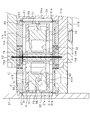
- the drive unit 70 includes a core 71 (71a, 71b), a coil 72, magnets 74A, 74B, 75A, 75B, and the like.
- the core 71 is formed in a “U” shape by a paramagnetic material.
- a coil 72 is attached to the outer periphery of the “U” -shaped bottom portion 71 a of the core 71.
- a pair of "U" -shaped linear portions 71b in the core 71 are parallel to each other.
- Magnets 74A and 75A and magnets 74B and 75B are attached to the pair of straight portions 71b, respectively.
- the magnets 74A to 75B are permanent magnets formed of a ferromagnetic material.
- the magnets 74A to 75B are formed in a rectangular parallelepiped shape.
- the magnets 74A and 75B are attached to the linear portion 71b of the core 71 such that the S pole is positioned on the linear portion 71b side of the core 71 and the N pole is positioned on the valve body 31 (mover 76) side. .
- the magnets 74B and 75A are attached to the linear portion 71b of the core 71 so that the N pole is positioned on the linear portion 71b side of the core 71 and the S pole is positioned on the valve body 31 (mover 76) side. .
- the N pole of the magnet 74A faces the S pole of the magnet 74B
- the S pole of the magnet 75A faces the N pole of the magnet 75B.
- the facing surfaces of the magnets 74A and 74B are parallel, and the facing surfaces of the magnets 75A and 75B are parallel.
- predetermined direction In the longitudinal direction of the valve body 31 (hereinafter referred to as "predetermined direction"), the magnet 74A and the magnet 75A are disposed at a predetermined interval, and the magnet 74B and the magnet 75B are also disposed at a predetermined interval.
- a mover 76 is disposed between the magnets 74A and 75A and the magnets 74B and 75B via a portion of the housing 21.
- a portion of the housing 21 disposed between the magnet 74A and the magnet 74B and a portion disposed between the magnet 75A and the magnet 75B are thinly formed to facilitate the passage of the magnetic flux.
- the mover 76 is formed of a paramagnetic material in a square cylindrical shape.
- the width L3 of the mover 76 in the predetermined direction is shorter than the distance L4 between the end surface of the magnet 74B (74A) on the connection member 24 side and the end surface of the magnet 75B (75A) on the lid 27 side.
- the valve body 31 is inserted into the hollow portion of the mover 76.
- a mover 76 is fixed at the center of the valve body 31 in the predetermined direction. That is, in the valve body 31, the mover 76 is fixed to a portion located between the pair of plate springs 51. The mover 76 is not in contact with members other than the valve body 31.
- the mover 76 In the predetermined direction, the mover 76 is disposed at a central position (neutral position) of the magnet 74A (74B) and the magnet 75A (75B) by the magnetic force of the magnets 74A, 74B, 75A, 75B. In this state, the mover 76 is fixed to the valve body 31 supported by the pair of leaf springs 51 in the natural state. That is, in the drive unit 70, the position of the mover 76 in a state in which the leaf spring 51 supports the valve body 31 in a natural state causes an electromagnetic force to cause the valve body 31 (mover 76) to reciprocate in the predetermined direction. Not set to neutral position.
- the drive part 70 drives the valve body 31 in the said predetermined direction contactlessly by the electromagnetic force made to act on the needle
- the size of the predetermined gap 61g is maintained constant. That is, regardless of the position of the damper 60 in the predetermined direction, the size of the predetermined gap 61g is constant.
- the drive unit 70 drives the valve body 31 in a noncontact manner by the electromagnetic force, and the valve body 31 is driven in a noncontact manner with the main bodies 41A and 41B.
- the pair of leaf springs 51 exert on the valve body 31 a reaction force proportional to the amount of movement of the valve body 31.
- FIG. 6 when the valve body 31 is driven in the direction of the connection member 24, the range in which the C1b port and the A1b port of the first main body 41A communicate with each other through the opening flow path 32 of the valve body 31 is expanded. Ru.
- the range in which the C1b port of the first main body 41A and the B1b port are in communication with each other is reduced via the open flow passage 32 of the valve body 31. That is, the flow ratio of the refrigerant supplied from the C1b port (C0 port) to the A1b port (A0 port) is increased, and the flow ratio of the refrigerant supplied to the B1b port (B0 port) is decreased.
- the same refrigerant is caused to flow through the C1b port of each first main body 41A.
- the pressure caused by the refrigerant flowing from the C1b port of each first main body 41A toward the valve body 31 is offset.
- the lower straight portion 71b of the core 71 goes from the lower straight portion 71b to the upper straight portion 71b.
- a coil magnetic field is generated. Therefore, the magnetic field from the N pole of the magnet 74A to the S pole of the magnet 74B and the coil magnetic field weaken each other, and the magnetic field from the N pole of the magnet 75B to the S pole of the magnet 75A and the coil magnetic field strengthen each other.
- the mover 76 receives a magnetic force that attracts in the direction of the lid 27.
- the valve body 31 moves in the direction of the arrow F2 together with the mover 76.
- the drive unit 70 drives the valve body 31 in a noncontact manner by the electromagnetic force, and the valve body 31 is driven in a noncontact manner with the main bodies 41A and 41B.
- the pair of leaf springs 51 exert on the valve body 31 a reaction force proportional to the amount of movement of the valve body 31.
- FIG. 6 when the valve body 31 is driven in the direction of the lid 27, the range in which the C1b port and the B1b port of the first main body 41A communicate with each other is enlarged through the opening flow path 32 of the valve body 31. .
- the range in which the C1b port of the first main body 41A and the A1b port are in communication with each other is reduced via the open flow passage 32 of the valve body 31. That is, the flow ratio of the refrigerant supplied from the C1b port (C0 port) to the B1b port (B0 port) is increased, and the flow ratio of the refrigerant supplied to the A1b port (A0 port) is decreased.
- the flow rate of the refrigerant supplied from the C port (C0 port, C1b port) to the B port (B0 port, B1b port) is C port to A port
- the person of the present application paid attention to the fact that the valve body 31 vibrates in a specific range (hatching range) which is larger than the flow rate of the refrigerant supplied to (A0 port, A1b port).
- the pressure of the refrigerant supplied to the B port fluctuates relatively largely at the frequency of 22 Hz.
- the damper 60 is attached to the valve body 31.
- the valve body 31 vibrates in a predetermined direction
- the refrigerant flows in or out of the predetermined space 68.
- a resistance is generated, and a force that suppresses the movement of the damper 60 acts, so a damping force that attenuates the vibration of the valve body 31 acts on the valve body 31.
- the damper 60 the fluctuation of the pressure of the refrigerant supplied to the B port is suppressed.
- the elastic force corresponding to the amount of deformation of the plate spring 51 is applied in a predetermined direction by the pair of plate springs 51. Since the valve body 31 is supported movably in the predetermined direction by the pair of plate springs 51, the valve body 31 can be movably supported in a non-sliding manner. Then, the valve body 31 is driven in a predetermined direction in a noncontact manner by the electromagnetic force exerted by the drive unit 70. As a result, when driving the valve body 31, a frictional force is not generated, and the responsiveness of driving the valve body 31 can be improved. Furthermore, since the valve body 31 is driven in a non-sliding manner, the valve body 31 is not worn and can be used semipermanently as compared with a general valve body with sliding.
- the valve body 31 is supported by a pair of leaf springs 51, and an electromagnetic force is exerted between the pair of leaf springs 51 in the predetermined direction. For this reason, it can suppress that the valve body 31 shakes at the time of being driven.
- the plate spring 51 and the valve body 31 are housed inside the container.
- a damper 60 is attached to the valve body 31, and a predetermined space 68, 69 partitioned by the inner surfaces 21a, 27a, 24a of the container and the damper 60 is formed.
- a predetermined gap 61g which causes the inside and the outside of the predetermined space 68, 69 to communicate with each other in a predetermined direction is formed between the inner surface 21a, 27a, 24a of the container and the damper 60. Therefore, when the damper 60 is driven in the predetermined direction together with the valve body 31, the refrigerant flows into and out of the predetermined spaces 68 and 69 through the predetermined gaps 61g.
- the valve body 31 is formed with an open flow passage 32 which opens at a predetermined length L1 in a predetermined direction on the predetermined surface 31a.
- a plurality of ports A1b port, C1b port, B1b port opening in the opposite surface 41a opposite to the predetermined surface 31a are formed side by side at an interval L2 shorter than the predetermined length L1 in the predetermined direction. It is done.
- the container in which the plate spring 51 and the valve body 31 are housed has the first main body 41A housed therein. Therefore, the refrigerant flowing from the port into the periphery of the valve body 31 flows in the container and flows into and out of the predetermined spaces 68 and 69 through the predetermined gap 61 g. Therefore, the refrigerant whose flow state is to be controlled by the valve body 31 can be used as a refrigerant that attenuates the vibration of the valve body 31, and it is not necessary to separately prepare a refrigerant dedicated to the damper 60.
- the damper 60 is attached to the valve body 31 outside the plate spring 51 in the predetermined direction. For this reason, in comparison with the configuration in which the damper 60 is attached to the valve body 31 inside the plate spring 51 in the predetermined direction, the predetermined space 68 divided by the inner surface 21a, 27a, 24a of the container and the damper 60. , 69 can be easily reduced, and the predetermined spaces 68, 69 can be easily formed.
- the damper 60 is formed in plate shape, while being able to simplify the shape of the damper 60, the space which arrange
- the predetermined gap 61g is annularly formed between the inner surfaces 21a, 27a, 24a of the container and the outer peripheral surface 61 of the damper 60. For this reason, it can suppress that the resistance of a refrigerant
- the damper 60 is fixed to the valve body 31 such that the major surface 62 having the largest area is perpendicular to the predetermined direction. For this reason, when the damper 60 is driven in a predetermined direction together with the valve body 31, the refrigerant can be applied vertically to the damper 60, so that the damper 60 can be prevented from tilting and thus the valve 31 can be tilted. .
- the size of the predetermined gap 61g is maintained constant by the drive unit 70 when the valve body 31 is driven in a predetermined direction without contact. For this reason, when the valve body 31 is driven, it is possible to suppress a change in the flow of the refrigerant passing through the predetermined gap 61g, and it becomes easy to stabilize the attitude of the damper 60 and hence the attitude of the valve body 31.
- Predetermined spaces 68 and 69 are formed at the end of the container in the predetermined direction. For this reason, in the flow ratio control valve 10, the predetermined spaces 68 and 69 can be easily secured, and interference between other components and the damper 60 can be easily suppressed.
- the size of the predetermined gap 61g is set to 0.2 to 5 mm according to the type and characteristics of the refrigerant. Therefore, an appropriate damping force can be applied to the valve body 31 to be driven, and the vibration of the valve body 31 can be damped, and the responsiveness of the valve body 31 can be prevented from being lowered.
- the positioning pin restricts the rotation of the damper 60 along a plane perpendicular to the predetermined direction. Therefore, it is possible to reliably prevent the predetermined gap 61g from changing due to the rotation of the damper 60, and it is possible to suppress the disturbance of the attitude of the damper 60 and hence the attitude of the valve body 31.
- the electromagnetic force acts on the mover 76 fixed to the valve body 31. For this reason, the mover 76 on which the electromagnetic force acts can be separated from the valve body 31, and the degree of freedom in design of the valve body 31 can be improved.
- the plate spring 51 is fixed to the second main body 41B such that the main surface having the largest area is perpendicular to the predetermined direction. For this reason, the plate spring 51 supports the valve body 31 so as to maintain a gap between the predetermined surface 31a of the valve body 31 and the opposing surface 41a of the first main body 41A, and only the elastic force along the predetermined direction.
- the structure which makes the valve body 31 act can be easily realized.
- the position of the valve body 31 (mover 76) in the state which supports the valve body 31 in the leaf spring 51 in the natural state is not making the electromagnetic force which makes the valve body 31 reciprocate act. It is set to the neutral position. According to such a configuration, in a state where the leaf spring 51 supports the valve body 31 in a natural state and the electromagnetic force is not applied by the drive unit 70, the valve body 31 can be maintained in the neutral position in the predetermined direction. . Therefore, by controlling the electromagnetic force applied to the mover 76 based on the neutral position, it is possible to easily reciprocate the valve body 31 with good reproducibility. Furthermore, the flow rate of the refrigerant in the state where the electromagnetic force is not applied by the drive unit 70 can be stably stabilized.
- the predetermined surface 31a of the valve body 31 and the opposing surface 41a of the first main body 41A are finished to a predetermined flatness.
- the plate spring 51 supports the valve body 31 such that the predetermined surface 31 a and the opposing surface 41 a have a predetermined degree of parallelism. According to such a configuration, the flatness and parallelism of the predetermined surface 31a of the valve body 31 and the opposing surface 41a of the main body 41 are managed, so the accuracy of the gap formed between the predetermined surface 31a and the opposing surface 41a Can be improved.
- the first main body 41A is provided on both sides of the valve body 31.
- a plurality of similar A1b ports, C1b ports, and B1b ports are formed in each of the first main bodies 41A. Therefore, by flowing the same refrigerant through the A1b port, the C1b port, and the B1b port of each first main body 41A, the pressure by the refrigerant flowing toward the valve body 31 from the C1b port of each first main body 41A is It can be offset. Therefore, the pressure of the refrigerant flowing from the C1b port toward the valve body 31 can suppress displacement of the valve body 31 in a direction away from the C1b port. Further, the rigidity required for the plate spring 51 can be reduced, and a thinner plate spring 51 can be employed.
- the positioning pin may be omitted as long as the damper 60 can be restricted from rotating along a plane perpendicular to the predetermined direction.
- the damper 60 if the main surface 62 of the damper 60 has a portion that is not perpendicular to the predetermined direction, by arranging the portions in pairs symmetrically, when the damper 60 is driven in the predetermined direction together with the valve body 31, The force to tilt the damper 60 can be offset.
- Adopt a configuration in which the size of the predetermined gap 61g decreases as the amount of movement of the valve body 31 from the neutral position increases when the valve body 31 is driven in a predetermined direction without contact by the drive unit 70. You can also. According to such a configuration, it is possible to increase the damping force acting on the valve body 31 as the amount of movement of the valve body 31 from the neutral position increases.
- the damper 60 may be attached to only one end 36 of the both ends 36 of the valve body 31 in the predetermined direction. In that case, the damper 60 may be attached to the lower end 36 by the arrangement of the flow ratio control valve 10.
- the damper 60 When the damper 60 is attached to the end portion 36 disposed on the upper side, air may stay in the predetermined space partitioned by the damper 60, and the damping force by the damper 60 may be reduced.
- the damper 60 is attached to the lower end 36, air is less likely to stay in the predetermined space divided by the damper 60, and the damping force by the damper 60 is prevented from being reduced. Can.
- the pair of leaf springs 51 may support a portion other than the both ends 36 of the valve body 31, for example, a portion slightly closer to the center.
- the position of the valve body 31 (the mover 76) in a state where the leaf spring 51 supports the valve body 31 in a natural state is not applied with an electromagnetic force that causes the valve body 31 to reciprocate in the longitudinal direction It can also be set other than the neutral position.
- plate spring 51 each attached to the both ends 36 of the valve body 31 can also employ
- a liquid (fluid) may be supplied to the A0 port (pressurized port), air may be supplied and discharged to the C0 port (output port), and a liquid may be discharged from the B0 port (exhaust port).
- the relationship between the distance L5 between the mutually separated ends of the two open flow channels 32 and the distance L6 between the A1b port and the B1b port is as follows. It can be changed.
- L6 L L5. In this case, as shown in FIG. 14, it can be used as a flow path switching valve having a dead zone near the current of 0 mA, and the start of fluid flow can be stabilized.
- the damper 60 can suppress the vibration of the valve body 31.
- the drive part 70 should just drive the valve body 31 (movable member) in a predetermined direction non-contactingly by the electromagnetic force made to act between a pair of leaf springs 51 in a predetermined direction, and the coil 72 and the core 71
- the configuration of the magnets 74A to 75B can be arbitrarily changed.
- the mover 76 and the valve body 31 can be integrally formed of a paramagnetic material.
- the valve body 31 (movable member) is constituted by the mover itself, and the open channel 32 is formed in the mover.
- SYMBOLS 10 Flow rate ratio control valve (electromagnetic actuator), 20 ... Valve mechanism, 31 ... Valve body (movable member), 31a ... Predetermined surface, 32 ... Opening flow path, 36 ... End part, 41A ... 1st main body, 41B ... 1st 2 main body, 41a: opposite surface, 41b: first surface, 42: connection flow channel, 43: connection flow channel, 44: connection flow channel, 51: plate spring, 60: damper, 61g: predetermined gap, 68: predetermined space 69: predetermined space 70: drive unit 76: mover.
Landscapes
- Engineering & Computer Science (AREA)
- General Engineering & Computer Science (AREA)
- Mechanical Engineering (AREA)
- Physics & Mathematics (AREA)
- Electromagnetism (AREA)
- Magnetically Actuated Valves (AREA)
- Sliding Valves (AREA)
Abstract
流量比制御弁(10)は、変形量に応じた弾性力を所定方向へ加える一対の板ばね(51)と、一対の板ばね(51)により所定方向へ移動可能に支持された弁体(31)と、所定方向において一対の板ばね(51)の間で作用させる電磁力により、弁体(31)を非接触で所定方向へ駆動する駆動部(70)と、板ばね(51)及び弁体(31)を内部に収納した容器(21,24,27)と、弁体(31)に取り付けられ、容器の内面とで区画した所定空間を形成し、所定空間の内部と外部とを所定方向に連通させる所定隙間を、内面との間に形成したダンパ(60)と、を備える。
Description
本出願は、2017年12月25日に出願された日本出願番号2017-247779号に基づくもので、ここにその記載内容を援用する。
本開示は、電磁力により可動部材を駆動する電磁アクチュエータに関する。
従来、この種の電磁アクチュエータとして、弁体(可動部材)と本体との間に隙間が形成されるように、弁体の両端部をそれぞれ板ばねにより支持し、弁体を電磁力により非接触で往復駆動する流路切替弁がある(特許文献1参照)。こうした構成によれば、弁体と本体とが擦れない状態で弁体を往復駆動することができるため、流路を切り替える応答性を向上させることができる。
ところで、特許文献1に記載の流路切替弁では、弁体を駆動する際に摩擦力が発生することを抑制することができる反面、板ばねの弾性力が作用する方向に弁体が振動し始めると、弁体の振動が止まりにくいことに本願開示者は着目した。
本開示は、こうした課題を解決するためになされたものであり、その主たる目的は、可動部材を駆動する応答性を向上させるとともに、可動部材の振動を抑制することのできる電磁アクチュエータを提供することにある。
上記課題を解決するための第1の手段は、電磁アクチュエータであって、
変形量に応じた弾性力を所定方向へ加える一対の板ばねと、
前記一対の板ばねにより前記所定方向へ移動可能に支持された可動部材と、
前記所定方向において前記一対の板ばねの間で作用させる電磁力により、前記可動部材を非接触で前記所定方向へ駆動する駆動部と、
前記板ばね及び前記可動部材を内部に収納した容器と、
前記可動部材に取り付けられ、前記容器の内面とで区画した所定空間を形成し、前記所定空間の内部と外部とを前記所定方向に連通させる所定隙間を、前記内面との間に形成したダンパと、
を備える。
変形量に応じた弾性力を所定方向へ加える一対の板ばねと、
前記一対の板ばねにより前記所定方向へ移動可能に支持された可動部材と、
前記所定方向において前記一対の板ばねの間で作用させる電磁力により、前記可動部材を非接触で前記所定方向へ駆動する駆動部と、
前記板ばね及び前記可動部材を内部に収納した容器と、
前記可動部材に取り付けられ、前記容器の内面とで区画した所定空間を形成し、前記所定空間の内部と外部とを前記所定方向に連通させる所定隙間を、前記内面との間に形成したダンパと、
を備える。
上記構成によれば、一対の板ばねにより、板ばねの変形量に応じた弾性力が所定方向へ加えられる。可動部材は、一対の板ばねにより上記所定方向へ移動可能に支持されているため、可動部材を非摺動で移動可能に支持することができる。そして、駆動部によって作用させられる電磁力により、可動部材が非接触で所定方向へ駆動される。その結果、可動部材を駆動する際に摩擦力が発生せず、可動部材を駆動する応答性を向上させることができる。さらに、可動部材は一対の板ばねにより支持されており、上記所定方向において一対の板ばねの間で電磁力が作用させられる。このため、駆動される際に可動部材がぶれることを抑制することができる。
板ばね及び可動部材は、容器の内部に収納されている。ダンパが可動部材に取り付けられ、容器の内面とダンパとで区画された所定空間が形成されている。そして、所定空間の内部と外部とを所定方向に連通させる所定隙間が、容器の内面とダンパとの間に形成されている。このため、可動部材と共にダンパが所定方向へ駆動されると、所定隙間を通じて所定空間の内部へ流体が流入出する。したがって、所定隙間を流体が通過する際の抵抗により、可動部材の振動を減衰させる減衰力を作用させることができ、可動部材の振動を抑制することができる。さらに、可動部材が他の部材と摺動することなく、可動部材の振動を減衰させることができるため、可動部材の応答性が低下することを抑制することができる。
第2の手段では、前記可動部材は、所定面において前記所定方向に所定長で開口する開口流路が形成された弁体であり、前記所定面に対向する対向面に開口する複数のポートが、前記所定方向に前記所定長よりも短い間隔で並んで形成され、且つ前記複数のポートにそれぞれ接続された接続流路が形成された本体を備え、前記容器は、前記本体を内部に収納している。
上記構成によれば、本体に形成された接続流路を通じて、各接続流路に接続された各ポートに対して流体を流入出させることができる。弁体には、所定面において所定方向に所定長で開口する開口流路が形成されている。本体には、上記所定面に対向する対向面に開口する複数のポートが、上記所定方向に上記所定長よりも短い間隔で並んで形成されている。このため、駆動部により弁体を上記所定方向に駆動することで、複数のポートが弁体の開口流路を介して接続される状態、すなわち流体の流通状態を制御することができる。
さらに、板ばね及び弁体(可動部材)を内部に収納した容器は、本体を内部に収納している。このため、上記ポートから弁体の周囲に流入した流体は、容器の内部を流通して、上記所定隙間を通じて上記所定空間の内部へ流入出する。したがって、弁体により流通状態を制御する対象である流体を、可動部材の振動を減衰させる流体として用いることができ、ダンパ専用の流体を別途用意する必要がない。
第3の手段では、前記所定方向において、前記ダンパは前記可動部材に対して前記板ばねよりも外側に取り付けられている。このため、所定方向においてダンパが可動部材に対して板ばねよりも内側に取り付けられた構成と比較して、容器の内面とダンパとで区画された所定空間を小さくし易くなり、所定空間を容易に形成することができる。
第4の手段では、前記ダンパは、板状に形成されており、前記所定隙間は、前記内面と前記ダンパの外周面との間に環状に形成されている。
上記構成によれば、ダンパは板状に形成されているため、ダンパの形状を簡素にすることができるとともに、ダンパを配置するスペースを小さくすることができる。そして、所定隙間は、容器の内面とダンパの外周面との間に環状に形成されている。このため、ダンパの一部に流体の抵抗が偏って作用することを抑制することができ、ダンパの姿勢、ひいては可動部材の姿勢を安定させ易くなる。
第5の手段では、前記ダンパは、最も面積の大きい主面が前記所定方向に垂直となるように、前記可動部材に固定されている。このため、可動部材と共にダンパが所定方向へ駆動された際に、ダンパに垂直に流体を当てることができ、ダンパが傾くこと、ひいては可動部材が傾くことを抑制することができる。
第6の手段では、前記駆動部により、前記可動部材が非接触で前記所定方向へ駆動された際に、前記所定隙間の大きさが一定に維持される。このため、可動部材が駆動された際に、所定隙間を通過する流体の流れが変化することを抑制することができ、ダンパの姿勢、ひいては可動部材の姿勢を安定させ易くなる。
第7の手段では、前記所定方向において、前記容器の端部に前記所定空間が形成されている。このため、電磁アクチュエータにおいて、所定空間を容易に確保することができ、他の部品とダンパとが干渉することを抑制し易くなる。
具体的には、第8の手段のように、前記所定隙間の大きさは0.2~5mmであるといった構成を採用することができる。こうした構成によれば、駆動される可動部材に適度な減衰力を作用させることができ、可動部材の振動を減衰させつつ、可動部材の応答性が低下することを抑制することができる。なお、所定の隙間の大きさは、流体の種類や特性に応じて変更するとよい。
第9の手段は、電磁アクチュエータであって、
変形量に応じた弾性力を所定方向へ加える一対の板ばねと、
前記一対の板ばねにより前記所定方向へ移動可能に支持され、液体の流通状態を制御する弁体と、
前記所定方向において前記一対の板ばねの間で作用させる電磁力により、前記弁体を非接触で前記所定方向へ駆動する駆動部と、
前記板ばね及び前記弁体を内部に収納した容器と、
前記弁体に取り付けられ、前記容器の内面との間に所定隙間を形成し、前記所定隙間に前記所定方向へ前記液体を通過させるダンパと、
を備える。
変形量に応じた弾性力を所定方向へ加える一対の板ばねと、
前記一対の板ばねにより前記所定方向へ移動可能に支持され、液体の流通状態を制御する弁体と、
前記所定方向において前記一対の板ばねの間で作用させる電磁力により、前記弁体を非接触で前記所定方向へ駆動する駆動部と、
前記板ばね及び前記弁体を内部に収納した容器と、
前記弁体に取り付けられ、前記容器の内面との間に所定隙間を形成し、前記所定隙間に前記所定方向へ前記液体を通過させるダンパと、
を備える。
上記構成によれば、弁体により、液体の流通状態が制御される。弁体にダンパが取り付けられており、容器の内面とダンパとの間に所定隙間が形成されている。そして、ダンパは、所定隙間に所定方向へ液体を通過させる。このため、弁体と共にダンパが所定方向へ駆動されると、所定隙間を液体が通過する際の抵抗により、弁体の振動を減衰させる減衰力を作用させることができ、弁体の振動を抑制することができる。さらに、弁体が他の部材と摺動することなく、弁体の振動を減衰させることができるため、弁体の応答性が低下することを抑制することができる。しかも、弁体により流通状態を制御する対象である液体を、弁体の振動を減衰させる液体として用いているため、ダンパ専用の液体を別途用意する必要がない。
第10の手段では、前記弁体には、所定面において前記所定方向に所定長で開口する開口流路が形成されており、前記所定面に対向する対向面に開口する複数のポートが、前記所定方向に前記所定長よりも短い間隔で並んで形成され、且つ前記複数のポートにそれぞれ接続された接続流路が形成された本体を備え、前記容器は、前記本体を内部に収納している。こうした構成によれば、第2の手段と同様の作用効果を奏することができる。
第11の手段では、前記所定方向において、前記ダンパは前記弁体に対して前記板ばねよりも外側に取り付けられている。こうした構成によれば、第3の手段と同様の作用効果を奏することができる。
第12の手段では、前記所定方向に垂直な平面に沿って前記ダンパが回転することを規制する位置決めピンを備える。
上記構成によれば、位置決めピンにより、所定方向に垂直な平面に沿ってダンパが回転することが規制される。このため、ダンパが回転して所定隙間が変化することを確実に防ぐことができ、ダンパの姿勢、ひいては可動部材の姿勢が乱れることを抑制することができる。
本開示についての上記目的およびその他の目的、特徴や利点は、添付の図面を参照しながら下記の詳細な記述により、より明確になる。
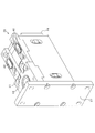
流量比制御弁を示す斜視断面図。
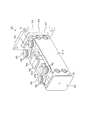
弁機構のポート周辺を示す斜視図。
ポート、本体、板ばね、磁石等を示す斜視図。
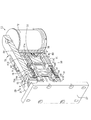
図3から一方のポート及び第1本体を取り除いた状態を示す斜視図。
流量比制御弁を示す斜視断面図。
弁機構を示す斜視断面図。
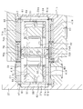
非励磁状態の弁機構を示す正面視断面図。
負方向の励磁状態の弁機構を示す正面視断面図。
正方向の励磁状態の弁機構を示す正面視断面図。
駆動電流と流量と振動発生範囲との関係を示すグラフ。
比較例の流量比制御弁のBポート圧力を示すタイムチャート。
本実施形態の流量比制御弁のBポート圧力を示すタイムチャート。
弁機構の変更例を示す斜視断面図。
駆動電流と流量との関係の一例を示すグラフ。
駆動電流と流量との関係の変更例を示すグラフ。
駆動電流と流量との関係の他の変更例を示すグラフ。
以下、共通ポートから2つの出力ポートへ供給される冷媒(液体)の流量比を制御する流量比制御弁に具現化した一実施形態について、図面を参照しつつ説明する。
図1~3に示すように、流量比制御弁10(電磁アクチュエータに相当)は、弁機構20と駆動部70とを備えている。弁機構20と駆動部70とは、接続部材24を介して接続されている。駆動部70は、弁機構20の弁体31(図4参照)を駆動する。
弁機構20は、ハウジング21、弁体31、第1本体41A(本体)、第2本体41B、板ばね51、蓋27等を備えている。ハウジング21、弁体31、第1本体41A、第2本体41B、板ばね51、蓋27は、非磁性体により形成されている。
図2は、図1の流量比制御弁10から、駆動部70を取り除いた状態を示している。図2に示すように、ハウジング21は、四角筒状(複数の部品から成る)に形成されている。ハウジング21には、冷媒(流体に相当)を入力するC0ポート(共通ポート)、冷媒を出力するA0ポート(第1出力ポート)、冷媒を出力するB0ポート(第2出力ポート)が設けられている。C0ポート、A0ポート、B0ポートは、非磁性体により形成されている。C0ポート、A0ポート、B0ポートには、それぞれ入力流路、第1出力流路、第2出力流路が接続されている。入力流路は、ハウジング21の内面で開口している。第1出力流路及び第2出力流路は、第1本体41Aに接続されている。
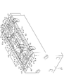
図3は、図2の弁機構20からハウジング21及び蓋27を取り除いた状態を示している。図4は、図3の弁機構20から、C0ポートと、一方のA0ポート,B0ポート,第1本体41Aとを取り除いた状態を示している。ハウジング21の内部には、弁体31、本体41A,41B、板ばね51、磁石74A,74B,75A,75B等が収容されている。本体41A,41Bは、直方体状(平板状)に形成されている。第1本体41Aは、ハウジング21に固定されている。第2本体41Bは、第1本体41Aに固定されている。弁体31は、直方体状(平板状)に形成されている。
並列に配置された第2本体41Bの間に、弁体31が配置されている。第2本体41Bと弁体31との間には、隙間が形成されている。すなわち、第2本体41Bと弁体31とは非接触状態になっている。
弁体31は、板ばね51を介して第2本体41Bに固定されている。詳しくは、弁体31の長手方向の両端部36には、板ばね51がそれぞれ取り付けられている。板ばね51は、ばね鋼等のばね性材料により、矩形板状に形成されている。板ばね51の所定部分には、スリット51aが形成されている。板ばね51にスリット51aが形成されることにより、板ばね51は蛇行する所定パターンに形成されている。板ばね51の厚みは、板ばね51が所定の剛性を有し、板ばね51が所定の弾性力を発生するように設定されている。板ばね51の2つの短辺部分51bがそれぞれ第2本体41Bに固定されている。板ばね51は、最も面積の大きい主面(図3,4における垂直面)が弁体31の長手方向に垂直となるように、第2本体41Bに取り付けられている。こうした構成により、弁体31(可動部材に相当)は、一対の板ばね51により弁体31の長手方向(所定方向に相当)に移動可能に支持されている。
弁体31の所定面31aと第2本体41Bの第1面41bとは同一平面上に位置している。図6に示すように、弁体31の所定面31aに第1本体41Aの対向面41aが対向している。そして、第2本体41Bの第1面41bは、第1本体41Aの対向面41aに対向している。弁体31の所定面31aと第1本体41Aの対向面41aとの間には、隙間が形成されている。このように、弁体31には、他の部材と摺動する部分が存在していない。
図6に示すように、弁体31の所定面31aには、弁体31の長手方向(以下、「所定方向」という)に所定長L1で開口する開口流路32が2つ形成されている。開口流路32は、弁体31を所定面31aに垂直な方向へ貫通し、長軸の長さが所定長L1の長孔になっている。なお、開口流路32が、弁体31の所定面31a側にそれぞれ形成された凹部になっており、弁体31を貫通していない構成を採用することもできる。
それぞれの第1本体41Aには、対向面41aに開口するA1bポート,C1bポート,B1bポート(複数のポートに相当)が形成されている。A1bポート,C1bポート,B1bポートは、弁体31の長手方向に所定長L1よりも短い間隔L2で並んで形成されている。第1本体41Aには、A1bポート,C1bポート,B1bポートにそれぞれ接続された接続流路42,43,44が形成されている。接続流路42,43,44は、それぞれ上記第1出力流路、入力流路、第2出力流路に接続されている。なお、接続流路43は、ハウジング21内の空間を介して入力流路に接続されている。ハウジング21内の空間は、シール部材47、シール部材48(図3参照)によりシールされている。
弁体31の所定面31a及び本体41の対向面41aは、所定の平面度に仕上げられている。また、板ばね51は、所定面31aと対向面41aとが所定の平行度となるように、弁体31を支持している。詳しくは、弁体31の長手方向の両端部36が、板ばね51の中央を貫通してそれぞれ固定されている。
そして、板ばね51は、弁体31の長手方向(板ばね51の主面に垂直な方向)への弁体31の移動量に応じて、弁体31に弾性力を加える。詳しくは、板ばね51は、弁体31の長手方向への弁体31の移動量、すなわち板ばね51の変形量に比例した弾性力を弁体31に加える。
上記所定方向において、弁体31の両端部36には、それぞれダンパ60が取り付けられている。すなわち、上記所定方向において、ダンパ60は弁体31に対して板ばね51よりも外側に取り付けられている。ダンパ60は、矩形板状に形成されている。ダンパ60は、その外周面61がハウジング21の内面21aに沿う形状に形成されている。これにより、ハウジング21の内面21aとダンパ60の外周面61との間に、環状の所定隙間61gが形成されている。ダンパ60は、最も面積の大きい主面62が上記所定方向に垂直となるように、弁体31に固定されている。
ハウジング21の内面21aと蓋27の内面27aとダンパ60とにより区画されて、所定空間68が形成されている。所定空間68は、上記所定方向において、ハウジング21、蓋27、及び接続部材24で構成される容器の端部、詳しくは蓋27に形成されている。ハウジング21の内面21aと接続部材24の内面24aとダンパ60とにより区画されて、所定空間69が形成されている。所定空間69は、上記所定方向において、ハウジング21、蓋27、及び接続部材24で構成される容器の端部、詳しくは接続部材24に形成されている。容器は、弁体31、板ばね51、第1本体41A、及び第2本体41Bを、内部に収納している。
所定隙間61gは、所定空間68,69の内部と外部とを上記所定方向に連通させている。所定隙間61gの大きさは、冷媒(流体)の種類や特性に応じて0.2~5mmに設定されている。所定隙間61gが小さ過ぎると、所定隙間61gを通過する冷媒の流動抵抗が大きくなり過ぎ、弁体31の応答性が低下するおそれがある。一方、所定隙間61gが大き過ぎると、所定隙間61gを通過する冷媒の流動抵抗が小さくなり過ぎ、弁体31の振動を減衰させる効果が小さくなるおそれがある。ダンパ60は、2つの位置決めピン(図示略)により弁体31に対して位置決めされている。2つの位置決めピンは、上記所定方向に垂直な平面に沿ってダンパ60が回転することを規制する。
次に、図1,5を参照して、駆動部70の構成を説明する。駆動部70は、コア71(71a,71b)、コイル72、磁石74A,74B,75A,75B等を備えている。
コア71は、常磁性体材料により、「U」字形状に形成されている。コア71における「U」字形状の底部71aの外周には、コイル72が取り付けられている。コア71における「U」字形状の一対の直線部71bは、互いに平行になっている。
一対の直線部71bには、磁石74A,75Aと磁石74B,75Bとがそれぞれ取り付けられている。磁石74A~75Bは、強磁性体材料により形成された永久磁石である。磁石74A~75Bは、直方体状に形成されている。磁石74A,75Bは、コア71の直線部71b側にS極が位置し、弁体31(可動子76)側にN極が位置するように、コア71の直線部71bにそれぞれ取り付けられている。磁石74B,75Aは、コア71の直線部71b側にN極が位置し、弁体31(可動子76)側にS極が位置するように、コア71の直線部71bにそれぞれ取り付けられている。磁石74AのN極と磁石74BのS極とが対向しており、磁石75AのS極と磁石75BのN極とが対向している。磁石74A,74Bの互いに対向する面は平行になっており、磁石75A,75Bの互いに対向する面は平行になっている。弁体31の長手方向(以下、「所定方向」という)において、磁石74Aと磁石75Aとが所定間隔で配置されており、磁石74Bと磁石75Bとが同じく所定間隔で配置されている。
磁石74A,75Aと磁石74B,75Bとの間には、上記ハウジング21の一部分を介して可動子76が配置されている。ハウジング21のうち、磁石74Aと磁石74Bとの間に配置される部分、及び磁石75Aと磁石75Bとの間に配置される部分は、磁束を透過させ易いように薄く形成されている。可動子76は、常磁性体材料により、四角筒状に形成されている。上記所定方向における可動子76の幅L3は、磁石74B(74A)の接続部材24側の端面と磁石75B(75A)の蓋27側の端面との間隔L4よりも短くなっている。可動子76の中空部には、弁体31が挿通されている。上記所定方向において、弁体31の中央に可動子76が固定されている。すなわち、弁体31において、一対の板ばね51の間に位置する部分に可動子76が固定されている。可動子76は、弁体31以外の部材とは接触していない。
上記所定方向において、可動子76は、磁石74A,74B,75A,75Bの磁力により磁石74A(74B)と磁石75A(75B)との中央位置(中立位置)に配置している。この状態で、自然状態の一対の板ばね51により支持された弁体31に、可動子76が固定されている。すなわち、駆動部70において、板ばね51が自然状態で弁体31を支持する状態における可動子76の位置は、弁体31(可動子76)を上記所定方向に往復駆動させる電磁力を作用させていない中立位置に設定されている。そして、駆動部70は、上記所定方向において一対の板ばね51の間で可動子76に作用させる電磁力により、弁体31を非接触で上記所定方向へ駆動する。駆動部70により、弁体31が上記所定方向へ駆動された際に、上記所定隙間61gの大きさは一定に維持される。すなわち、上記所定方向におけるダンパ60の位置にかかわらず、所定隙間61gの大きさは一定である。
次に、図7~9を参照して、駆動部70により、弁体31の長手方向(所定方向)に弁体31を往復駆動する原理を説明する。
駆動部70のコイル72に電流を流していない非励磁状態では、図7に示すように、磁石74AのN極から磁石74BのS極へ向かう磁界、及び磁石75BのN極から磁石74BのS極へ向かう磁界が発生する。この状態では、可動子76は、上記所定方向において中立位置で釣り合って静止している。この状態では、一対の板ばね51は自然状態になっており、一対の板ばね51から弁体31へ力が作用していない。また、この状態では、図6に示すように、第1本体41AのA1bポート及びB1bポートは、弁体31によりそれぞれ所定量開かれている。
駆動部70のコイル72に負方向の電流を流した負方向の励磁状態では、図8に矢印H1で示すように、コア71の上側の直線部71bから下側の直線部71bへ向かうコイル磁界が発生する。このため、磁石74AのN極から磁石74BのS極へ向かう磁界とコイル磁界とは強め合い、磁石75BのN極から磁石75AのS極へ向かう磁界とコイル磁界とは弱め合う。その結果、可動子76は、接続部材24の方向へ引き付ける磁力を受ける。そして、矢印F1で示すように、可動子76と共に弁体31が矢印F1の方向へ移動する。この際に、駆動部70は電磁力により弁体31を非接触で駆動し、弁体31は本体41A,41Bと非接触で駆動される。これに対して、一対の板ばね51は、弁体31の移動量に比例した抗力を弁体31に作用させる。図6において、弁体31が接続部材24の方向へ駆動されると、弁体31の開口流路32を介して、第1本体41AのC1bポートとA1bポートとが連通される範囲が拡大される。一方、弁体31の開口流路32を介して、第1本体41AのC1bポートとB1bポートとが連通される範囲が縮小される。すなわち、C1bポート(C0ポート)から、A1bポート(A0ポート)へ供給される冷媒の流量比が大きくされ、B1bポート(B0ポート)へ供給される冷媒の流量比が小さくされる。
ここで、それぞれの第1本体41AのC1bポートに、同様の冷媒を流通させる。これにより、それぞれの第1本体41AのC1bポートから弁体31に向かって流れる冷媒による圧力が相殺される。
また、駆動部70のコイル72に正方向の電流を流した正方向の励磁状態では、図9に矢印H2で示すように、コア71の下側の直線部71bから上側の直線部71bへ向かうコイル磁界が発生する。このため、磁石74AのN極から磁石74BのS極へ向かう磁界とコイル磁界とは弱め合い、磁石75BのN極から磁石75AのS極へ向かう磁界とコイル磁界とは強め合う。その結果、可動子76は、蓋27の方向へ引き付ける磁力を受ける。そして、矢印F2で示すように、可動子76と共に弁体31が矢印F2の方向へ移動する。この際に、駆動部70は電磁力により弁体31を非接触で駆動し、弁体31は本体41A,41Bと非接触で駆動される。これに対して、一対の板ばね51は、弁体31の移動量に比例した抗力を弁体31に作用させる。図6において、弁体31が蓋27の方向へ駆動されると、弁体31の開口流路32を介して、第1本体41AのC1bポートとB1bポートとが連通される範囲が拡大される。一方、弁体31の開口流路32を介して、第1本体41AのC1bポートとA1bポートとが連通される範囲が縮小される。すなわち、C1bポート(C0ポート)から、B1bポート(B0ポート)へ供給される冷媒の流量比が大きくされ、A1bポート(A0ポート)へ供給される冷媒の流量比が小さくされる。
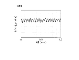
ここで、図10に示すように、ダンパ60がない場合は、Cポート(C0ポート、C1bポート)からBポート(B0ポート、B1bポート)へ供給される冷媒の流量が、CポートからAポート(A0ポート、A1bポート)へ供給される冷媒の流量よりも多くなる特定の範囲(ハッチング範囲)において、弁体31が振動することに本願開示者は着目した。この場合、図11に示すように、ダンパ60がない比較例では、Bポートに供給される冷媒の圧力が、22Hzの周波数で比較的大きく変動している。
この原因として、図9に示すように、弁体31が蓋27の方向へ移動した場合に、撓んだ状態の板ばね51に矢印Qで示すように冷媒の流れが当たることが考えられる。詳しくは、板ばねの主面に沿って流れる冷媒の流速が高くなると、冷媒の流れに渦が発生し、この渦により板ばねに変則的な力が作用する。いわゆる旗が風になびく状態と同様に、冷媒の流れにより板ばね51が共振し、弁体31が所定方向に振動すると考えられる。しかも、弁体31に摺動部分が存在しないため、一旦弁体31が振動し始めると、この振動を減衰させる力が作用しにくく、弁体31の振動が止まりにくいといった課題が生じる。
この点、本実施形態では、弁体31にダンパ60が取り付けられている。このため、弁体31が所定方向に振動すると、所定空間68の内部に対して冷媒が流入又は流出する。そして、所定隙間61gを冷媒が通過する際に抵抗が生じ、ダンパ60の移動を抑制する力が作用するため、弁体31の振動を減衰させる減衰力が弁体31に作用する。その結果、図12に示すように、ダンパ60を備える本実施形態では、Bポートに供給される冷媒の圧力の変動が抑制されている。
以上詳述した本実施形態は、以下の利点を有する。
・一対の板ばね51により、板ばね51の変形量に応じた弾性力が所定方向へ加えられる。弁体31は、一対の板ばね51により上記所定方向へ移動可能に支持されているため、弁体31を非摺動で移動可能に支持することができる。そして、駆動部70によって作用させられる電磁力により、弁体31が非接触で所定方向へ駆動される。その結果、弁体31を駆動する際に摩擦力が発生せず、弁体31を駆動する応答性を向上させることができる。さらに、弁体31を非摺動で駆動するため、弁体31に摩耗が生じず、摺動を伴う一般的な弁体と比較して半永久的に使用することができる。
・弁体31は一対の板ばね51により支持されており、上記所定方向において一対の板ばね51の間で電磁力が作用させられる。このため、駆動される際に弁体31がぶれることを抑制することができる。
・板ばね51及び弁体31は、容器の内部に収納されている。ダンパ60が弁体31に取り付けられ、容器の内面21a,27a,24aとダンパ60とで区画された所定空間68,69が形成されている。そして、所定空間68,69の内部と外部とを所定方向に連通させる所定隙間61gが、容器の内面21a,27a,24aとダンパ60との間に形成されている。このため、弁体31と共にダンパ60が所定方向へ駆動されると、所定隙間61gを通じて所定空間68,69の内部へ冷媒が流入出する。したがって、所定隙間61gを冷媒が通過する際の抵抗により、弁体31の振動を減衰させる減衰力を作用させることができ、弁体31の振動を抑制することができる。さらに、弁体31が他の部材と摺動することなく、弁体31の振動を減衰させることができるため、弁体31の応答性が低下することを抑制することができる。
・第1本体41Aに形成された接続流路42,43,44を通じて、各接続流路42,43,44に接続された各A1bポート,C1bポート,B1bポートに対して冷媒を流入出させることができる。弁体31には、所定面31aにおいて所定方向に所定長L1で開口する開口流路32が形成されている。第1本体41Aには、上記所定面31aに対向する対向面41aに開口する複数のポートA1bポート,C1bポート,B1bポートが、上記所定方向に上記所定長L1よりも短い間隔L2で並んで形成されている。このため、駆動部70により弁体31を上記所定方向に駆動することで、複数のポートA1bポート,C1bポート,B1bポートが弁体31の開口流路32を介して接続される状態、すなわち冷媒の流通状態を制御ことができる。
・板ばね51及び弁体31を内部に収納した容器は、第1本体41Aを内部に収納している。このため、上記ポートから弁体31の周囲に流入した冷媒は、容器の内部を流通して、上記所定隙間61gを通じて上記所定空間68,69の内部へ流入出する。したがって、弁体31により流通状態を制御する対象である冷媒を、弁体31の振動を減衰させる冷媒として用いることができ、ダンパ60専用の冷媒を別途用意する必要がない。
・所定方向において、ダンパ60は弁体31に対して板ばね51よりも外側に取り付けられている。このため、所定方向においてダンパ60が弁体31に対して板ばね51よりも内側に取り付けられた構成と比較して、容器の内面21a,27a,24aとダンパ60とで区画された所定空間68,69を小さくし易くなり、所定空間68,69を容易に形成することができる。
・ダンパ60は板状に形成されているため、ダンパ60の形状を簡素にすることができるとともに、ダンパ60を配置するスペースを小さくすることができる。そして、所定隙間61gは、容器の内面21a,27a,24aとダンパ60の外周面61との間に環状に形成されている。このため、ダンパ60の一部に冷媒の抵抗が偏って作用することを抑制することができ、ダンパ60の姿勢、ひいては弁体31の姿勢を安定させ易くなる。
・ダンパ60は、最も面積の大きい主面62が所定方向に垂直となるように、弁体31に固定されている。このため、弁体31と共にダンパ60が所定方向へ駆動された際に、ダンパ60に垂直に冷媒を当てることができ、ダンパ60が傾くこと、ひいては弁体31が傾くことを抑制することができる。
・駆動部70により、弁体31が非接触で所定方向へ駆動された際に、所定隙間61gの大きさが一定に維持される。このため、弁体31が駆動された際に、所定隙間61gを通過する冷媒の流れが変化することを抑制することができ、ダンパ60の姿勢、ひいては弁体31の姿勢を安定させ易くなる。
・所定方向において、容器の端部に所定空間68,69が形成されている。このため、流量比制御弁10において、所定空間68,69を容易に確保することができ、他の部品とダンパ60とが干渉することを抑制し易くなる。
・所定隙間61gの大きさは、冷媒の種類や特性に応じて0.2~5mmに設定されている。このため、駆動される弁体31に適度な減衰力を作用させることができ、弁体31の振動を減衰させつつ、弁体31の応答性が低下することを抑制することができる。
・位置決めピンにより、所定方向に垂直な平面に沿ってダンパ60が回転することが規制される。このため、ダンパ60が回転して所定隙間61gが変化することを確実に防ぐことができ、ダンパ60の姿勢、ひいては弁体31の姿勢が乱れることを抑制することができる。
・弁体31に固定された可動子76に電磁力が作用させられる。このため、電磁力が作用させられる可動子76と、弁体31とを別体にすることができ、弁体31の設計の自由度を向上させることができる。
・板ばね51は、最も面積の大きい主面が所定方向に垂直となるように、第2本体41Bに固定されている。このため、板ばね51は、弁体31の所定面31aと第1本体41Aの対向面41aとの間の隙間を維持するように弁体31を支持し、且つ所定方向に沿った弾性力のみを弁体31に作用させる構成を、容易に実現することができる。
・一対の板ばね51により弁体31の両端部36が支持されているため、弁体31の支持を安定させ易くなる。
・駆動部70において、板ばね51が自然状態で弁体31を支持する状態における弁体31(可動子76)の位置は、弁体31を所定方向に往復駆動させる電磁力を作用させていない中立位置に設定されている。こうした構成によれば、板ばね51が自然状態で弁体31を支持し、且つ駆動部70により電磁力を作用させていない状態において、弁体31を所定方向の中立位置に維持することができる。このため、中立位置を基準として、可動子76に作用させる電磁力を制御することにより、弁体31を容易に再現性よく往復駆動することができる。さらに、駆動部70により電磁力を作用させていない状態における冷媒の流量を、一定に安定させることができる。
・弁体31の所定面31a及び第1本体41Aの対向面41aは、所定の平面度に仕上げられている。板ばね51は、所定面31aと対向面41aとが所定の平行度となるように、弁体31を支持している。こうした構成によれば、弁体31の所定面31a及び本体41の対向面41aの平面度及び平行度が管理されているため、所定面31aと対向面41aとの間に形成される隙間の精度を向上させることができる。
・弁体31を挟んで両側に第1本体41Aが設けられている。そして、それぞれの第1本体41Aには、同様の複数のA1bポート,C1bポート,B1bポートが形成されている。このため、それぞれの第1本体41AのA1bポート,C1bポート,B1bポートに、同様の冷媒を流通させることにより、それぞれの第1本体41AのC1bポートから弁体31に向かって流れる冷媒による圧力を相殺することができる。したがって、C1bポートから弁体31に向かって流れる冷媒の圧力により、弁体31がC1bポートから離れる方向へ変位することを抑制することができる。また、板ばね51に要求される剛性を低下させることができ、より薄い板ばね51を採用することができる。
なお、上記各実施形態を、以下のように変更して実施することもできる。
・上記所定方向に垂直な平面に沿ってダンパ60が回転することを規制することができれば、位置決めピンを省略してもよい。
・ダンパ60の主面62に上記所定方向に垂直でない部分があったとしても、その部分を対にして対称に配置することにより、弁体31と共にダンパ60が所定方向へ駆動された際に、ダンパ60を傾ける力を相殺することができる。
・駆動部70により、弁体31が非接触で所定方向へ駆動された際に、中立位置からの弁体31の移動量が大きくなるほど、所定隙間61gの大きさが小さくなる構成を採用することもできる。こうした構成によれば、中立位置からの弁体31の移動量が大きくなるほど、弁体31に作用する減衰力を大きくすることができる。
・上記所定方向において、弁体31の両端部36のうち、一方の端部36のみにダンパ60を取り付けてもよい。その場合、流量比制御弁10の配置により、下側に配置される端部36にダンパ60を取り付けるとよい。上側に配置される端部36にダンパ60を取り付けた場合は、ダンパ60により区画された所定空間内に空気が滞留するおそれがあり、ダンパ60による減衰力が低下するおそれがある。この点、下側に配置される端部36にダンパ60を取り付けた場合は、ダンパ60により区画された所定空間内に空気が滞留しにくく、ダンパ60による減衰力が低下することを抑制することができる。
・一対の板ばね51が、弁体31の両端部36以外の部分、例えば若干中央寄りの部分を支持する構成を採用することもできる。
・駆動部70において、板ばね51が自然状態で弁体31を支持する状態における弁体31(可動子76)の位置を、弁体31を長手方向に往復駆動させる電磁力を作用させていない中立位置以外に設定することもできる。
・弁体31の両端部36にそれぞれ取り付けられた板ばね51の弾性力が、互いに等しくない構成を採用することもできる。
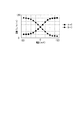
・A0ポート(加圧ポート)へ液体(流体)を供給し、C0ポート(出力ポート)に対して空気を供給及び排出し、B0ポート(排気ポート)から液体を排出してもよい。そして、図13に示すように、所定方向において、2つの開口流路32の互いに離れた側の端同士の間隔L5と、A1bポートとB1bポートとの間隔L6との関係を、以下のように変更することができる。(1)L6≧L5。この場合は、図14に示すように、電流0mA付近に不感帯を有する流路切替弁として使用することができ、流体の流れ始めを安定させることができる。(2)L6<L5。この場合は、図15に示すように、電流0mA付近にコンスタントブリード流量を有する流路切替弁として使用することができ、流体の流量を変更する応答性を向上させることができる。(3)L6<<L5。この場合は、図16に示すように、AポートからCポートへ流す流体と、BポートからCポートへ流す流体とを混合する混合弁として使用することができる。また、第1本体41Aに形成されるポートの数は3つに限らず、2つや4つ以上であってもよい。これらの場合であっても、ダンパ60により、弁体31の振動を抑制することができる。
・駆動部70は、所定方向において一対の板ばね51の間で作用させる電磁力により、弁体31(可動部材)を非接触で所定方向へ駆動するものであればよく、コイル72、コア71、磁石74A~75B等の構成を任意に変更することができる。
・可動子76と弁体31とを常磁性体材料により、一体に形成することもできる。この場合、可動子そのものにより弁体31(可動部材)が構成され、可動子に開口流路32が形成される。
本開示は、実施形態に準拠して記述されたが、本開示は当該実施形態や構造に限定されるものではないと理解される。本開示は、様々な変形例や均等範囲内の変形をも包含する。加えて、様々な組み合わせや形態、さらには、それらに一要素のみ、それ以上、あるいはそれ以下、を含む他の組み合わせや形態をも、本開示の範疇や思想範囲に入るものである。
10…流量比制御弁(電磁アクチュエータ)、20…弁機構、31…弁体(可動部材)、31a…所定面、32…開口流路、36…端部、41A…第1本体、41B…第2本体、41a…対向面、41b…第1面、42…接続流路、43…接続流路、44…接続流路、51…板ばね、60…ダンパ、61g…所定隙間、68…所定空間、69…所定空間、70…駆動部、76…可動子。
Claims (12)
- 変形量に応じた弾性力を所定方向へ加える一対の板ばねと、
前記一対の板ばねにより前記所定方向へ移動可能に支持された可動部材と、
前記所定方向において前記一対の板ばねの間で作用させる電磁力により、前記可動部材を非接触で前記所定方向へ駆動する駆動部と、
前記板ばね及び前記可動部材を内部に収納した容器と、
前記可動部材に取り付けられ、前記容器の内面とで区画した所定空間を形成し、前記所定空間の内部と外部とを前記所定方向に連通させる所定隙間を、前記内面との間に形成したダンパと、
を備える電磁アクチュエータ。 - 前記可動部材は、所定面において前記所定方向に所定長で開口する開口流路が形成された弁体であり、
前記所定面に対向する対向面に開口する複数のポートが、前記所定方向に前記所定長よりも短い間隔で並んで形成され、且つ前記複数のポートにそれぞれ接続された接続流路が形成された本体を備え、
前記容器は、前記本体を内部に収納している、請求項1に記載の電磁アクチュエータ。 - 前記所定方向において、前記ダンパは前記可動部材に対して前記板ばねよりも外側に取り付けられている、請求項1又は2に記載の電磁アクチュエータ。
- 前記ダンパは、板状に形成されており、
前記所定隙間は、前記内面と前記ダンパの外周面との間に環状に形成されている、請求項3に記載の電磁アクチュエータ。 - 前記ダンパは、最も面積の大きい主面が前記所定方向に垂直となるように、前記可動部材に固定されている、請求項4に記載の電磁アクチュエータ。
- 前記駆動部により、前記可動部材が非接触で前記所定方向へ駆動された際に、前記所定隙間の大きさが一定に維持される、請求項1~5のいずれか1項に記載の電磁アクチュエータ。
- 前記所定方向において、前記容器の端部に前記所定空間が形成されている、請求項1~6のいずれか1項に記載の電磁アクチュエータ。
- 前記所定隙間の大きさは0.2~5mmである、請求項1~7のいずれか1項に記載の電磁アクチュエータ。
- 変形量に応じた弾性力を所定方向へ加える一対の板ばねと、
前記一対の板ばねにより前記所定方向へ移動可能に支持され、液体の流通状態を制御する弁体と、
前記所定方向において前記一対の板ばねの間で作用させる電磁力により、前記弁体を非接触で前記所定方向へ駆動する駆動部と、
前記板ばね及び前記弁体を内部に収納した容器と、
前記弁体に取り付けられ、前記容器の内面との間に所定隙間を形成し、前記所定隙間に前記所定方向へ前記液体を通過させるダンパと、
を備える電磁アクチュエータ。 - 前記弁体には、所定面において前記所定方向に所定長で開口する開口流路が形成されており、
前記所定面に対向する対向面に開口する複数のポートが、前記所定方向に前記所定長よりも短い間隔で並んで形成され、且つ前記複数のポートにそれぞれ接続された接続流路が形成された本体を備え、
前記容器は、前記本体を内部に収納している、請求項9に記載の電磁アクチュエータ。 - 前記所定方向において、前記ダンパは前記弁体に対して前記板ばねよりも外側に取り付けられている、請求項9又は10に記載の電磁アクチュエータ。
- 前記所定方向に垂直な平面に沿って前記ダンパが回転することを規制する位置決めピンを備える、請求項1~11のいずれか1項に記載の電磁アクチュエータ。
Priority Applications (3)
| Application Number | Priority Date | Filing Date | Title |
|---|---|---|---|
| KR1020207017226A KR20200086350A (ko) | 2017-12-25 | 2018-10-16 | 전자 액추에이터 |
| CN201880078418.0A CN111433501A (zh) | 2017-12-25 | 2018-10-16 | 电磁致动器 |
| US16/905,632 US11268628B2 (en) | 2017-12-25 | 2020-06-18 | Electromagnetic actuator |
Applications Claiming Priority (2)
| Application Number | Priority Date | Filing Date | Title |
|---|---|---|---|
| JP2017-247779 | 2017-12-25 | ||
| JP2017247779A JP6955436B2 (ja) | 2017-12-25 | 2017-12-25 | 電磁アクチュエータ |
Related Child Applications (1)
| Application Number | Title | Priority Date | Filing Date |
|---|---|---|---|
| US16/905,632 Continuation US11268628B2 (en) | 2017-12-25 | 2020-06-18 | Electromagnetic actuator |
Publications (1)
| Publication Number | Publication Date |
|---|---|
| WO2019130737A1 true WO2019130737A1 (ja) | 2019-07-04 |
Family
ID=67066856
Family Applications (1)
| Application Number | Title | Priority Date | Filing Date |
|---|---|---|---|
| PCT/JP2018/038486 Ceased WO2019130737A1 (ja) | 2017-12-25 | 2018-10-16 | 電磁アクチュエータ |
Country Status (6)
| Country | Link |
|---|---|
| US (1) | US11268628B2 (ja) |
| JP (1) | JP6955436B2 (ja) |
| KR (1) | KR20200086350A (ja) |
| CN (1) | CN111433501A (ja) |
| TW (1) | TWI730261B (ja) |
| WO (1) | WO2019130737A1 (ja) |
Families Citing this family (5)
| Publication number | Priority date | Publication date | Assignee | Title |
|---|---|---|---|---|
| JP1720711S (ja) * | 2020-07-29 | 2022-07-26 | 電磁弁 | |
| JP1711581S (ja) * | 2020-09-07 | 2022-04-01 | 電磁弁 | |
| JP1711456S (ja) * | 2020-09-07 | 2022-04-01 | 電磁弁 | |
| JP1711580S (ja) * | 2020-09-07 | 2022-04-01 | 電磁弁 | |
| JP1711457S (ja) * | 2020-09-07 | 2022-04-01 | 電磁弁 |
Citations (2)
| Publication number | Priority date | Publication date | Assignee | Title |
|---|---|---|---|---|
| JPS61228176A (ja) * | 1985-04-01 | 1986-10-11 | Hitachi Ltd | 油圧制御用閉ル−プ式比例電磁弁 |
| JP2017187162A (ja) * | 2016-03-30 | 2017-10-12 | Ckd株式会社 | 流路切替弁、及びその製造方法 |
Family Cites Families (56)
| Publication number | Priority date | Publication date | Assignee | Title |
|---|---|---|---|---|
| US723801A (en) | 1903-01-15 | 1903-03-24 | Owen A Rauschenberg | Gas-reversing valve. |
| US2690529A (en) | 1950-03-01 | 1954-09-28 | Bofors Ab | Suspension arrangement for movable members |
| US2983286A (en) | 1959-01-19 | 1961-05-09 | Ranco Inc | Reversing valve |
| US2974682A (en) | 1959-06-11 | 1961-03-14 | Internat Heater Company | Reversing valve for heat pumps |
| US3400736A (en) | 1966-05-31 | 1968-09-10 | Controls Co Of America | Reversing valve |
| US3369790A (en) | 1967-05-19 | 1968-02-20 | Robertshaw Controls Co | Fluid system and method and parts therefor or the like |
| JPS5013963B1 (ja) | 1969-11-14 | 1975-05-23 | ||
| US3773082A (en) | 1971-01-05 | 1973-11-20 | Bio Logics Products | Fluid valve |
| US3894561A (en) | 1974-03-14 | 1975-07-15 | Controls Co Of America | Four-way reversing valve with differential area operator |
| US4138089A (en) | 1977-08-09 | 1979-02-06 | The United States Of America As Represented By The Secretary Of The Department Of Health, Education And Welfare | Slide valve |
| US4340202A (en) | 1977-10-07 | 1982-07-20 | Emerson Electric Co. | Four way valve |
| US4327774A (en) | 1978-11-06 | 1982-05-04 | Robertshaw Controls Company | Reversing valve construction and parts therefor and methods of making the same |
| US4664136A (en) | 1981-10-01 | 1987-05-12 | South Bend Controls Inc. | Pressure regulating transducer |
| US4463332A (en) * | 1983-02-23 | 1984-07-31 | South Bend Controls, Inc. | Adjustable, rectilinear motion proportional solenoid |
| US4569504A (en) | 1983-05-20 | 1986-02-11 | Doyle Michael J | Solenoid |
| AU569173B2 (en) | 1984-09-20 | 1988-01-21 | Ranco Inc. | Refrigerant reversing valve pilot valve mounting |
| US4644760A (en) | 1984-11-05 | 1987-02-24 | Kabushiki Kaisha Saginomiya Seisakusho | Reversible four-way valve for reversible refrigerating cycle |
| JPS61127985A (ja) | 1984-11-28 | 1986-06-16 | Nippon Denso Co Ltd | バルブ装置 |
| US4605197A (en) | 1985-01-18 | 1986-08-12 | Fema Corporation | Proportional and latching pressure control device |
| JPS61229309A (ja) | 1985-04-03 | 1986-10-13 | Teijin Seiki Co Ltd | 電磁駆動装置 |
| US4635683A (en) | 1985-10-03 | 1987-01-13 | Ford Motor Company | Variable force solenoid |
| JPS6260780U (ja) | 1985-10-04 | 1987-04-15 | ||
| US4988074A (en) | 1988-05-17 | 1991-01-29 | Hi-Ram, Inc. | Proportional variable force solenoid control valve |
| JP2679309B2 (ja) * | 1989-11-17 | 1997-11-19 | 松下電器産業株式会社 | 自動調圧弁 |
| US5070908A (en) | 1991-03-06 | 1991-12-10 | Delco Electronics Corporation | Vacuum valve |
| GB9218610D0 (en) | 1992-09-03 | 1992-10-21 | Electro Hydraulic Technology L | Linear motor valve |
| US6182942B1 (en) | 1995-12-01 | 2001-02-06 | Microhydraulics, Inc. | Actuator |
| JPH10196831A (ja) | 1997-01-10 | 1998-07-31 | Kenji Masuda | 比例電磁制御弁 |
| JP3839562B2 (ja) | 1997-09-17 | 2006-11-01 | カヤバ工業株式会社 | スプール弁 |
| US6068288A (en) | 1998-03-26 | 2000-05-30 | Sturman/Tlx Llc | Dynamic control valve system adapted for inflatable restraint systems for vehicles |
| JP2001074158A (ja) | 1999-09-02 | 2001-03-23 | Ebara Corp | ソレノイド及び流体制御弁 |
| US6281772B1 (en) | 2001-01-29 | 2001-08-28 | Fema Corporation Of Michigan | Dynamic dampening in a frictionless solenoid valve |
| DE10331254B4 (de) | 2003-07-10 | 2006-05-04 | Chemagen Biopolymer-Technologie Aktiengesellschaft | Vorrichtung und Verfahren zum Abtrennen von magnetischen oder magnetisierbaren Partikeln aus einer Flüssigkeit |
| JP2006046414A (ja) * | 2004-08-02 | 2006-02-16 | Smc Corp | 3ポート電磁弁 |
| JP4651394B2 (ja) | 2005-01-13 | 2011-03-16 | 三菱電機株式会社 | 四方弁 |
| JP2007211857A (ja) | 2006-02-08 | 2007-08-23 | Denso Corp | 電磁スプール弁 |
| US20080099705A1 (en) | 2006-10-25 | 2008-05-01 | Enfield Technologies, Llc | Retaining element for a mechanical component |
| JP5168714B2 (ja) | 2007-04-05 | 2013-03-27 | シンフォニアテクノロジー株式会社 | アクチュエータ |
| JP4315220B2 (ja) * | 2007-06-29 | 2009-08-19 | 株式会社デンソー | バルブ装置 |
| US8056576B2 (en) | 2007-08-27 | 2011-11-15 | Husco Automotive Holdings Llc | Dual setpoint pressure controlled hydraulic valve |
| IL187922A (en) | 2007-12-06 | 2012-01-31 | Eitan Rivlin | Frictionless pressure balanced proportioning valve assembly |
| JP5281099B2 (ja) | 2008-01-07 | 2013-09-04 | バンダービルト ユニバーシティ | ソレノイドバルブアセンブリ |
| CN201526728U (zh) * | 2009-10-16 | 2010-07-14 | 中国航天科技集团公司第六研究院第十一研究所 | 电磁阀用隔油减振装置 |
| US8579250B1 (en) | 2010-06-16 | 2013-11-12 | Daniel Theobald | High precision energy efficient valve |
| US9464729B2 (en) | 2011-06-14 | 2016-10-11 | Brooks Instrument, Llc | Pressure balanced valve |
| JP5617830B2 (ja) * | 2011-12-12 | 2014-11-05 | 株式会社デンソー | 油圧制御装置 |
| DE102013226586A1 (de) | 2013-12-19 | 2015-07-09 | Robert Bosch Gmbh | Ventil mit einem Verbindungselement |
| JP6378980B2 (ja) | 2014-09-04 | 2018-08-22 | Kyb株式会社 | ソレノイドバルブ |
| CN204141015U (zh) | 2014-10-15 | 2015-02-04 | 北京华德液压工业集团有限责任公司 | 软切换的电磁换向阀 |
| WO2016133974A1 (en) * | 2015-02-17 | 2016-08-25 | Enfield Technologies, Inc. | Solenoid apparatus |
| EP3309432B1 (en) | 2015-05-14 | 2020-06-17 | Zhejiang Sanhua Climate and Appliance Controls Group Co. Ltd. | Reversing valve and cooling system having same |
| CN104896143A (zh) | 2015-06-01 | 2015-09-09 | 广东美的暖通设备有限公司 | 六通换向阀及具有其的空调室外机、空调器 |
| US10018382B2 (en) | 2015-06-01 | 2018-07-10 | Gd Midea Heating & Ventilating Equipment Co., Ltd. | Six-way directional valve, outdoor unit for air conditioner having the same, and air conditioner |
| WO2016199946A1 (ko) | 2015-06-08 | 2016-12-15 | 삼성전자주식회사 | 공기 조화기 및 그 제어 방법 |
| WO2017170939A1 (ja) | 2016-03-30 | 2017-10-05 | Ckd株式会社 | 流路切替弁、及びその製造方法 |
| JP6416159B2 (ja) | 2016-07-25 | 2018-10-31 | Ckd株式会社 | 電磁アクチュエータ |
-
2017
- 2017-12-25 JP JP2017247779A patent/JP6955436B2/ja active Active
-
2018
- 2018-10-16 WO PCT/JP2018/038486 patent/WO2019130737A1/ja not_active Ceased
- 2018-10-16 CN CN201880078418.0A patent/CN111433501A/zh active Pending
- 2018-10-16 KR KR1020207017226A patent/KR20200086350A/ko not_active Ceased
- 2018-11-01 TW TW107138780A patent/TWI730261B/zh active
-
2020
- 2020-06-18 US US16/905,632 patent/US11268628B2/en active Active
Patent Citations (2)
| Publication number | Priority date | Publication date | Assignee | Title |
|---|---|---|---|---|
| JPS61228176A (ja) * | 1985-04-01 | 1986-10-11 | Hitachi Ltd | 油圧制御用閉ル−プ式比例電磁弁 |
| JP2017187162A (ja) * | 2016-03-30 | 2017-10-12 | Ckd株式会社 | 流路切替弁、及びその製造方法 |
Also Published As
| Publication number | Publication date |
|---|---|
| TWI730261B (zh) | 2021-06-11 |
| TW201928237A (zh) | 2019-07-16 |
| CN111433501A (zh) | 2020-07-17 |
| US20200318753A1 (en) | 2020-10-08 |
| JP6955436B2 (ja) | 2021-10-27 |
| KR20200086350A (ko) | 2020-07-16 |
| JP2019113129A (ja) | 2019-07-11 |
| US11268628B2 (en) | 2022-03-08 |
Similar Documents
| Publication | Publication Date | Title |
|---|---|---|
| US11268628B2 (en) | Electromagnetic actuator | |
| JP5453918B2 (ja) | 流量制御弁 | |
| JP2014167320A (ja) | 電磁サスペンション装置 | |
| JP2015112013A (ja) | 振動アクチュエータ、および携帯情報端末 | |
| JP6778238B2 (ja) | マウントブッシュ | |
| US20160049230A1 (en) | Magnetic armature | |
| CN107448529B (zh) | 主动型振动控制装置 | |
| KR20140010035A (ko) | 회전 솔레노이드 | |
| US10344887B2 (en) | Electromagnetic actuator | |
| JP2020060209A (ja) | マウントブッシュ | |
| JP4802307B2 (ja) | 振動アクチュエータ | |
| JP2019049362A (ja) | 流路切替弁、及びその製造方法 | |
| JP2003314608A (ja) | 緩衝装置 | |
| JP2013121275A (ja) | リニアアクチュエータ | |
| JP6902437B2 (ja) | スプールバルブ | |
| JP7028849B2 (ja) | 能動型防振装置 | |
| JP2019183937A (ja) | 電磁弁及び電磁弁用スプリング部材 | |
| JP5840972B2 (ja) | 磁気粘性流体緩衝器 | |
| JP2002206585A (ja) | 液体封入式振動吸収装置 | |
| JP2019029678A (ja) | 電磁アクチュエータ | |
| JPH06185656A (ja) | 回転型流量制御弁 | |
| WO2025211017A1 (ja) | 振動減衰装置 | |
| JP2023078896A (ja) | 電磁石 | |
| JP2001221272A (ja) | 磁気粘性流体流動型制振装置 | |
| JPS60157573A (ja) | バネ定数コントロ−ル用エアソレノイドバルブ |
Legal Events
| Date | Code | Title | Description |
|---|---|---|---|
| 121 | Ep: the epo has been informed by wipo that ep was designated in this application |
Ref document number: 18897402 Country of ref document: EP Kind code of ref document: A1 |
|
| ENP | Entry into the national phase |
Ref document number: 20207017226 Country of ref document: KR Kind code of ref document: A |
|
| NENP | Non-entry into the national phase |
Ref country code: DE |
|
| 122 | Ep: pct application non-entry in european phase |
Ref document number: 18897402 Country of ref document: EP Kind code of ref document: A1 |