WO2019123685A1 - 表示具 - Google Patents
表示具 Download PDFInfo
- Publication number
- WO2019123685A1 WO2019123685A1 PCT/JP2018/021858 JP2018021858W WO2019123685A1 WO 2019123685 A1 WO2019123685 A1 WO 2019123685A1 JP 2018021858 W JP2018021858 W JP 2018021858W WO 2019123685 A1 WO2019123685 A1 WO 2019123685A1
- Authority
- WO
- WIPO (PCT)
- Prior art keywords
- character
- state
- key chain
- image
- display tool
- Prior art date
- Legal status (The legal status is an assumption and is not a legal conclusion. Google has not performed a legal analysis and makes no representation as to the accuracy of the status listed.)
- Ceased
Links
Images


Classifications
-
- A—HUMAN NECESSITIES
- A63—SPORTS; GAMES; AMUSEMENTS
- A63H—TOYS, e.g. TOPS, DOLLS, HOOPS OR BUILDING BLOCKS
- A63H33/00—Other toys
- A63H33/42—Toy models or toy scenery not otherwise covered
-
- A—HUMAN NECESSITIES
- A63—SPORTS; GAMES; AMUSEMENTS
- A63J—DEVICES FOR THEATRES, CIRCUSES, OR THE LIKE; CONJURING APPLIANCES OR THE LIKE
- A63J19/00—Puppet, marionette, or shadow shows or theatres
-
- A—HUMAN NECESSITIES
- A63—SPORTS; GAMES; AMUSEMENTS
- A63H—TOYS, e.g. TOPS, DOLLS, HOOPS OR BUILDING BLOCKS
- A63H3/00—Dolls
- A63H3/003—Dolls specially adapted for a particular function not connected with dolls
-
- G—PHYSICS
- G09—EDUCATION; CRYPTOGRAPHY; DISPLAY; ADVERTISING; SEALS
- G09F—DISPLAYING; ADVERTISING; SIGNS; LABELS OR NAME-PLATES; SEALS
- G09F19/00—Advertising or display means not otherwise provided for
-
- A—HUMAN NECESSITIES
- A44—HABERDASHERY; JEWELLERY
- A44B—BUTTONS, PINS, BUCKLES, SLIDE FASTENERS, OR THE LIKE
- A44B15/00—Key-rings
- A44B15/005—Fobs
Definitions
- the present invention relates to a character display tool.
- Non-Patent Document 1 the stuffed toy is once placed on a shooting spot and then shot. Therefore, the arrangement of stuffed animals is limited. In addition, when putting a stuffed toy or figure in the angle of view, if you try to put the whole stuffed toy or figure in the angle of view, it can not be avoided that the hand holding it enters the angle of view.
- An object of the present invention is to provide a technique capable of enhancing the convenience in capturing a character by setting the angle of view.
- This indicator includes a first member and a second member that visually represents the character, and the first position and the second state can be taken in the first state and the second state rather than the first state. And a second state in which it is difficult to hold one member.
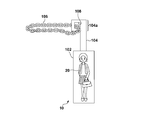
- FIG. 1 is an explanatory view showing a usage example of the key chain 10 according to the embodiment.
- real or unreal characters are represented in such a manner as to be visible.
- the unrealistic character may be, for example, a character of animation, cartoon or novel.
- the real character may be, for example, an entertainer, an actor or a historical person.
- the user 12 attaches the unused key chain 10 to a portable terminal 14 such as a smartphone, a cellular phone, or a tablet, or a bag or a belt.
- a portable terminal 14 such as a smartphone, a cellular phone, or a tablet, or a bag or a belt.
- the key chain 10 is first removed and deformed into a use state.
- the user 12 holds the camera of the portable terminal 14 toward the spot with one hand and holds the holding member of the key chain 10 in use with the other hand.
- the character member is placed within the angle of view of the camera. In this state, the user 12 performs imaging with a camera.
- FIG. 2 is a schematic view showing an example of an image 16 obtained as a result of imaging using the key chain 10 according to the embodiment.
- the character member 102 of the key chain 10 is reflected in the image 16 together with the landscape 18 of the spot.
- FIG. 2 shows that the user 12 holds the holding member 104 of the key chain 10 by hand.
- the key chain 10 according to the present embodiment it is possible to obtain an image 16 as if the character 20 was in the spot.
- FIG. 300a is a front view of the key chain 10 in use.
- the key chain 10 includes a plate-like character member 102 and a rod-like handle member 104.
- the character member 102 is a member that visually represents the character 20.
- the surface of the character member 102 may be subjected to processing for suppressing reflection. In this case, the reflection at the time of flash photography can be suppressed.
- the handle member 104 is rotatably attached to the character member 102.
- the handle member 104 is rotatable 360 degrees with respect to the character member 102, and the relative position between the character member 102 and the handle member 104 is maintained when no rotational torque is applied.
- the distal end 104a of the handle member 104 distal from the character member 102 is configured to allow attachment of the chain 106 or a strap.
- the distal end 104a is formed in an L shape, and the distal end 104a is provided with a hole 108 for passing the chain 106 and the strap.
- the chain 106 and the strap are members used to attach the key chain 10 to the portable terminal 14 and the bag.
- the handle member 104 in use functions as a grip.
- 300 b is a side view of the key chain 10 in use.
- 300 c is a rear view of the key chain 10 in use.
- the character member 102 includes a first transparent plate 110, a seal 112 on which an image of the character 20 is printed, and a second transparent plate 114.
- the character member 102 is created by sticking a seal 112 on the upper surface of the second transparent plate 114, and further overlapping the first transparent plate 110 thereon and fixing it with an adhesive.
- Each of the first transparent plate 110 and the second transparent plate 114 may be substantially transparent, and may be made of, for example, an acrylic plate or a transparent plastic plate.
- the character 20 is represented as a seal on which the image of the character 20 is printed.
- the present invention is not limited to this.
- the image of the character 20 may be drawn directly on the surface of a transparent plate.
- connection mechanism between the character member 102 and the handle member 104 includes a screw 116 and a spacer 118.
- the connection mechanism is provided on the back surface 102 a side of the character member 102, and is provided at a position where it is hidden by the character 20 (or overlapped with the image of the character 20) particularly when the character member 102 is viewed from the front.
- the connection mechanism may be provided below the image of the character 20.
- the spacer 118 is a doughnut-shaped member formed of Teflon (registered trademark), rubber, metal or the like, and is sandwiched between the back surface 102 a of the character member 102 and the front surface 104 b of the handle member 104.
- the screw 116 integrally fastens the handle member 104, the spacer 118 and the character member 102. Screws 116 pass through the hole provided at the proximal end 104 c of the handle member 104 closer to the character member 102 and the central hole of the spacer 118 and into the corresponding screw holes provided in the character member 102. Screwed together.
- the tightening torque of the screw 116 and the size and material of the spacer 118 allow the relative movement between the character member 102 and the handle member 104, and the character member 102 when no direct external force is applied. It is selected such that the relative position between the and the handle member 104 is maintained.
- FIG. 3B is a front view of the key chain 10 in another use state.
- the state of FIG. 3B is obtained. This state is convenient when displaying the character 20 at the upper right of the image. If the character 20 is to be displayed on the upper right of the image using the key chain 10 in the state of 300a, the holding member 104 and the hand holding the same will be reflected in the image.
- the key chain 10 in the state shown in FIG. 3B by inserting the character member 102 into the angle of view from the side of the image, the handle member 104 and the hand holding the same should not be reflected in the image. Can.
- FIG. 3C is a front view of the key chain 10 not in use.
- the state in which the relative position between the character member 102 and the handle member 104 can be taken includes the use state shown in 300 a and FIG. 3B and the non-use state in which the handle member 104 is harder to grip than the use state.
- the non-use state as shown in FIG. 3C, a part of the handle member 104 overlaps the character member 102 so as to be located on the back side of the character 20. Since the handle member 104 is hidden behind the character member 102, the user 12 can not easily hold the handle member 104.
- the entire appearance of the key chain 10 in the non-use state is similar to a normal key chain or key holder, and the discomfort when attaching the key chain 10 to the portable terminal 14 or bag is reduced or eliminated.
- the key chain 10 is configured such that the distal end 104 a of the handle member 104 does not overlap with the character member 102 in the non-use state. This can avoid interference between the character member 102 and the chain 106 attached to the distal end 104 a in the non-use state.
- the hand holding the handle member 104 does not enter into the angle of view.
- the holding hand can be prevented from entering the image.
- the following values can be provided to the user 12, for example.
- the user 12 attaches the unused key chain 10 to the portable terminal 14 or the bag and goes out.
- the user 12 encounters a spot where he / she wants to take a picture outside, he / she turns the holding member 104 of the key chain 10 by 180 degrees to bring it into use.
- the user 12 holds the handle member 104 and takes a picture of the spot with the character 20.
- the user 12 can easily take a picture with the character 20 on the go.
- the key chain 10 has the handle member 104 as a grip, photographing becomes easier.
- the unused key chain 10 is easy to collect and can be attached to the bag or the portable terminal 14.
- the present invention is not limited thereto.
- a three-dimensional image of the character 20 for example, a figure or a stuffed toy
- the character member 102 has the front surface where the character 20 can be seen and the back surface 102a where the character 20 can not be seen has been described, but the present invention is not limited to this.
- the character may be visible from either side of the character member.
- the handle member 104 is rotatably attached to the character member 102
- the present invention is not limited to this.
- a space may be provided inside the character member in which the handle member fits, and the handle member may be accommodated in the space in the non-use state, and the handle member may be taken out of the space in the use state.
- the character member and the handle member may be connected by a folding hinge and configured to be folded in the non-use state.
- an application program installed in the mobile terminal 14 may control the imaging function of the mobile terminal 14.
- the application program when executed by the portable terminal 14, the function of identifying the character 20 captured in the camera and the information of the identified character 20 on the portable terminal 14 via a network such as the Internet
- a function of displaying on the display of the portable terminal 14 and storing in the memory when executed by the portable terminal 14, the function of identifying the character 20 captured in the camera and the information of the identified character 20 on the portable terminal 14 via a network such as the Internet.
- the technical idea according to the embodiment may be represented by the following items.
- (Item 1) A first member and a second member that visually represent a character, wherein the relative positions of the first member and the second member can be the first state and the first state rather than the first state And a second state in which the second state is difficult to grip.
- (Item 2) The display tool according to Item 1, wherein the first member is rotatably attached to the second member.
- (Item 3) The display tool according to Item 1 or 2, wherein the first member overlaps the second member so as to be positioned on the back side of the character in the second state.
- the end of the first member that is distal from the second member in the first state is configured to be able to attach a member used to attach the indicator to another item
- the display tool according to any one of the above.
- the display tool according to any one of Items 1 to 4 wherein an end portion of the first member which is distal to the second member in the first state does not overlap with the second member in the second state.
- the connection mechanism between the first member and the second member is such that relative movement between the first member and the second member is possible and the direct force is not applied.
- the second member In the first state, the second member is imaged by the mobile terminal, The indicator according to any one of Items 1 to 6, wherein the indicator is attached to another article in the second state.
- the display tool according to Item 4 or 5, wherein the end is formed in an L shape. It is a portable terminal described in item 7, and A portable terminal comprising means for combining an image corresponding to the imaged character with an image of a real space when the character is imaged.
Landscapes
- Business, Economics & Management (AREA)
- Accounting & Taxation (AREA)
- Marketing (AREA)
- Physics & Mathematics (AREA)
- General Physics & Mathematics (AREA)
- Engineering & Computer Science (AREA)
- Theoretical Computer Science (AREA)
- Toys (AREA)
- Telephone Set Structure (AREA)
Priority Applications (1)
| Application Number | Priority Date | Filing Date | Title |
|---|---|---|---|
| US16/815,532 US20200206649A1 (en) | 2017-12-20 | 2020-03-11 | Display tool |
Applications Claiming Priority (2)
| Application Number | Priority Date | Filing Date | Title |
|---|---|---|---|
| JP2017-244377 | 2017-12-20 | ||
| JP2017244377A JP7137803B2 (ja) | 2017-12-20 | 2017-12-20 | 表示具 |
Related Child Applications (1)
| Application Number | Title | Priority Date | Filing Date |
|---|---|---|---|
| US16/815,532 Continuation US20200206649A1 (en) | 2017-12-20 | 2020-03-11 | Display tool |
Publications (1)
| Publication Number | Publication Date |
|---|---|
| WO2019123685A1 true WO2019123685A1 (ja) | 2019-06-27 |
Family
ID=66993326
Family Applications (1)
| Application Number | Title | Priority Date | Filing Date |
|---|---|---|---|
| PCT/JP2018/021858 Ceased WO2019123685A1 (ja) | 2017-12-20 | 2018-06-07 | 表示具 |
Country Status (3)
| Country | Link |
|---|---|
| US (1) | US20200206649A1 (enExample) |
| JP (1) | JP7137803B2 (enExample) |
| WO (1) | WO2019123685A1 (enExample) |
Citations (4)
| Publication number | Priority date | Publication date | Assignee | Title |
|---|---|---|---|---|
| JPH0713224A (ja) * | 1993-06-23 | 1995-01-17 | Yoshiyuki Takematsu | 模擬被写体同時撮影用具 |
| US5538166A (en) * | 1994-12-14 | 1996-07-23 | Matsuri Corporation | Combination plush doll and hanger assembly |
| JP3130223U (ja) * | 2006-11-24 | 2007-03-22 | メルヘンワールド株式会社 | キーホルダー |
| WO2010035462A1 (ja) * | 2008-09-24 | 2010-04-01 | 東京メタル株式会社 | 着脱自在式ハンガー |
-
2017
- 2017-12-20 JP JP2017244377A patent/JP7137803B2/ja active Active
-
2018
- 2018-06-07 WO PCT/JP2018/021858 patent/WO2019123685A1/ja not_active Ceased
-
2020
- 2020-03-11 US US16/815,532 patent/US20200206649A1/en not_active Abandoned
Patent Citations (4)
| Publication number | Priority date | Publication date | Assignee | Title |
|---|---|---|---|---|
| JPH0713224A (ja) * | 1993-06-23 | 1995-01-17 | Yoshiyuki Takematsu | 模擬被写体同時撮影用具 |
| US5538166A (en) * | 1994-12-14 | 1996-07-23 | Matsuri Corporation | Combination plush doll and hanger assembly |
| JP3130223U (ja) * | 2006-11-24 | 2007-03-22 | メルヘンワールド株式会社 | キーホルダー |
| WO2010035462A1 (ja) * | 2008-09-24 | 2010-04-01 | 東京メタル株式会社 | 着脱自在式ハンガー |
Also Published As
| Publication number | Publication date |
|---|---|
| JP2019110931A (ja) | 2019-07-11 |
| US20200206649A1 (en) | 2020-07-02 |
| JP7137803B2 (ja) | 2022-09-15 |
Similar Documents
| Publication | Publication Date | Title |
|---|---|---|
| US20150346590A1 (en) | Branded monopod apparatus | |
| EP3076265A3 (en) | Foldable phone with flexible display comprising a slidable back cover | |
| CN112166593A (zh) | 移动通信终端设备外壳 | |
| US12314081B2 (en) | Super smartphone | |
| JP2025146954A (ja) | スーパースマートフォン及びスマートフォンシステム | |
| CN108024064B (zh) | 一种移动终端和计算机可读取存储介质 | |
| WO2019123685A1 (ja) | 表示具 | |
| CN106941542B (zh) | 带投影功能的移动通信设备 | |
| TWI461815B (zh) | 電子裝置 | |
| KR101731889B1 (ko) | 가상현실 장치로 전환되는 휴대 단말 케이스 | |
| JP2009288613A5 (enExample) | ||
| CN108810387B (zh) | 多功能摄像头 | |
| CN105005170A (zh) | 折叠式臂式照相机架 | |
| CN211630223U (zh) | 一种便于手机拍摄的防光壳 | |
| JP2005010410A (ja) | 表示装置 | |
| JP3217153U (ja) | タブレット型端末収納ケース | |
| JP2003131755A (ja) | 携帯型通信端末装置 | |
| CN205910476U (zh) | 手持摄像设备镜头折拍器 | |
| KR20150000833U (ko) | 스마트폰 커버의 촬영보조 기능 | |
| KR20180076376A (ko) | 스테레오 사진 촬영을 위한 스마트폰 프레임 | |
| CN205453793U (zh) | 方便连接手机的拍摄装置 | |
| US9002187B1 (en) | Handheld subject framing apparatus for photograph | |
| JP3194999U (ja) | インカメラの不正撮影防止装置 | |
| KR101441621B1 (ko) | 플렉시블 디스플레이어가 구비된 휴대기기 케이스 | |
| TW201633159A (zh) | 可攜式電子裝置之附屬顯示裝置 |
Legal Events
| Date | Code | Title | Description |
|---|---|---|---|
| 121 | Ep: the epo has been informed by wipo that ep was designated in this application |
Ref document number: 18890912 Country of ref document: EP Kind code of ref document: A1 |
|
| NENP | Non-entry into the national phase |
Ref country code: DE |
|
| 122 | Ep: pct application non-entry in european phase |
Ref document number: 18890912 Country of ref document: EP Kind code of ref document: A1 |