WO2019117290A1 - 回転機械 - Google Patents
回転機械 Download PDFInfo
- Publication number
- WO2019117290A1 WO2019117290A1 PCT/JP2018/046117 JP2018046117W WO2019117290A1 WO 2019117290 A1 WO2019117290 A1 WO 2019117290A1 JP 2018046117 W JP2018046117 W JP 2018046117W WO 2019117290 A1 WO2019117290 A1 WO 2019117290A1
- Authority
- WO
- WIPO (PCT)
- Prior art keywords
- fiber
- fiber sheet
- moving blade
- blade
- sheet
- Prior art date
- Legal status (The legal status is an assumption and is not a legal conclusion. Google has not performed a legal analysis and makes no representation as to the accuracy of the status listed.)
- Ceased
Links
Images


Classifications
-
- F—MECHANICAL ENGINEERING; LIGHTING; HEATING; WEAPONS; BLASTING
- F01—MACHINES OR ENGINES IN GENERAL; ENGINE PLANTS IN GENERAL; STEAM ENGINES
- F01D—NON-POSITIVE DISPLACEMENT MACHINES OR ENGINES, e.g. STEAM TURBINES
- F01D25/00—Component parts, details, or accessories, not provided for in, or of interest apart from, other groups
- F01D25/04—Antivibration arrangements
- F01D25/06—Antivibration arrangements for preventing blade vibration
-
- F—MECHANICAL ENGINEERING; LIGHTING; HEATING; WEAPONS; BLASTING
- F04—POSITIVE - DISPLACEMENT MACHINES FOR LIQUIDS; PUMPS FOR LIQUIDS OR ELASTIC FLUIDS
- F04D—NON-POSITIVE-DISPLACEMENT PUMPS
- F04D29/00—Details, component parts, or accessories
- F04D29/26—Rotors specially for elastic fluids
- F04D29/32—Rotors specially for elastic fluids for axial flow pumps
- F04D29/321—Rotors specially for elastic fluids for axial flow pumps for axial flow compressors
- F04D29/324—Blades
-
- F—MECHANICAL ENGINEERING; LIGHTING; HEATING; WEAPONS; BLASTING
- F01—MACHINES OR ENGINES IN GENERAL; ENGINE PLANTS IN GENERAL; STEAM ENGINES
- F01D—NON-POSITIVE DISPLACEMENT MACHINES OR ENGINES, e.g. STEAM TURBINES
- F01D5/00—Blades; Blade-carrying members; Heating, heat-insulating, cooling or antivibration means on the blades or the members
- F01D5/12—Blades
- F01D5/28—Selecting particular materials; Particular measures relating thereto; Measures against erosion or corrosion
-
- F—MECHANICAL ENGINEERING; LIGHTING; HEATING; WEAPONS; BLASTING
- F01—MACHINES OR ENGINES IN GENERAL; ENGINE PLANTS IN GENERAL; STEAM ENGINES
- F01D—NON-POSITIVE DISPLACEMENT MACHINES OR ENGINES, e.g. STEAM TURBINES
- F01D25/00—Component parts, details, or accessories, not provided for in, or of interest apart from, other groups
- F01D25/005—Selecting particular materials
-
- F—MECHANICAL ENGINEERING; LIGHTING; HEATING; WEAPONS; BLASTING
- F01—MACHINES OR ENGINES IN GENERAL; ENGINE PLANTS IN GENERAL; STEAM ENGINES
- F01D—NON-POSITIVE DISPLACEMENT MACHINES OR ENGINES, e.g. STEAM TURBINES
- F01D5/00—Blades; Blade-carrying members; Heating, heat-insulating, cooling or antivibration means on the blades or the members
- F01D5/12—Blades
- F01D5/14—Form or construction
- F01D5/147—Construction, i.e. structural features, e.g. of weight-saving hollow blades
-
- F—MECHANICAL ENGINEERING; LIGHTING; HEATING; WEAPONS; BLASTING
- F01—MACHINES OR ENGINES IN GENERAL; ENGINE PLANTS IN GENERAL; STEAM ENGINES
- F01D—NON-POSITIVE DISPLACEMENT MACHINES OR ENGINES, e.g. STEAM TURBINES
- F01D5/00—Blades; Blade-carrying members; Heating, heat-insulating, cooling or antivibration means on the blades or the members
- F01D5/12—Blades
- F01D5/14—Form or construction
- F01D5/16—Form or construction for counteracting blade vibration
-
- F—MECHANICAL ENGINEERING; LIGHTING; HEATING; WEAPONS; BLASTING
- F01—MACHINES OR ENGINES IN GENERAL; ENGINE PLANTS IN GENERAL; STEAM ENGINES
- F01D—NON-POSITIVE DISPLACEMENT MACHINES OR ENGINES, e.g. STEAM TURBINES
- F01D5/00—Blades; Blade-carrying members; Heating, heat-insulating, cooling or antivibration means on the blades or the members
- F01D5/12—Blades
- F01D5/26—Antivibration means not restricted to blade form or construction or to blade-to-blade connections or to the use of particular materials
-
- F—MECHANICAL ENGINEERING; LIGHTING; HEATING; WEAPONS; BLASTING
- F01—MACHINES OR ENGINES IN GENERAL; ENGINE PLANTS IN GENERAL; STEAM ENGINES
- F01D—NON-POSITIVE DISPLACEMENT MACHINES OR ENGINES, e.g. STEAM TURBINES
- F01D5/00—Blades; Blade-carrying members; Heating, heat-insulating, cooling or antivibration means on the blades or the members
- F01D5/12—Blades
- F01D5/28—Selecting particular materials; Particular measures relating thereto; Measures against erosion or corrosion
- F01D5/282—Selecting composite materials, e.g. blades with reinforcing filaments
-
- F—MECHANICAL ENGINEERING; LIGHTING; HEATING; WEAPONS; BLASTING
- F04—POSITIVE - DISPLACEMENT MACHINES FOR LIQUIDS; PUMPS FOR LIQUIDS OR ELASTIC FLUIDS
- F04D—NON-POSITIVE-DISPLACEMENT PUMPS
- F04D29/00—Details, component parts, or accessories
- F04D29/02—Selection of particular materials
- F04D29/023—Selection of particular materials especially adapted for elastic fluid pumps
-
- F—MECHANICAL ENGINEERING; LIGHTING; HEATING; WEAPONS; BLASTING
- F04—POSITIVE - DISPLACEMENT MACHINES FOR LIQUIDS; PUMPS FOR LIQUIDS OR ELASTIC FLUIDS
- F04D—NON-POSITIVE-DISPLACEMENT PUMPS
- F04D29/00—Details, component parts, or accessories
- F04D29/26—Rotors specially for elastic fluids
- F04D29/32—Rotors specially for elastic fluids for axial flow pumps
- F04D29/38—Blades
-
- F—MECHANICAL ENGINEERING; LIGHTING; HEATING; WEAPONS; BLASTING
- F04—POSITIVE - DISPLACEMENT MACHINES FOR LIQUIDS; PUMPS FOR LIQUIDS OR ELASTIC FLUIDS
- F04D—NON-POSITIVE-DISPLACEMENT PUMPS
- F04D29/00—Details, component parts, or accessories
- F04D29/66—Combating cavitation, whirls, noise, vibration or the like; Balancing
- F04D29/661—Combating cavitation, whirls, noise, vibration or the like; Balancing especially adapted for elastic fluid pumps
-
- F—MECHANICAL ENGINEERING; LIGHTING; HEATING; WEAPONS; BLASTING
- F05—INDEXING SCHEMES RELATING TO ENGINES OR PUMPS IN VARIOUS SUBCLASSES OF CLASSES F01-F04
- F05D—INDEXING SCHEME FOR ASPECTS RELATING TO NON-POSITIVE-DISPLACEMENT MACHINES OR ENGINES, GAS-TURBINES OR JET-PROPULSION PLANTS
- F05D2220/00—Application
- F05D2220/30—Application in turbines
- F05D2220/32—Application in turbines in gas turbines
-
- F—MECHANICAL ENGINEERING; LIGHTING; HEATING; WEAPONS; BLASTING
- F05—INDEXING SCHEMES RELATING TO ENGINES OR PUMPS IN VARIOUS SUBCLASSES OF CLASSES F01-F04
- F05D—INDEXING SCHEME FOR ASPECTS RELATING TO NON-POSITIVE-DISPLACEMENT MACHINES OR ENGINES, GAS-TURBINES OR JET-PROPULSION PLANTS
- F05D2260/00—Function
- F05D2260/96—Preventing, counteracting or reducing vibration or noise
- F05D2260/961—Preventing, counteracting or reducing vibration or noise by mistuning rotor blades or stator vanes with irregular interblade spacing, airfoil shape
-
- F—MECHANICAL ENGINEERING; LIGHTING; HEATING; WEAPONS; BLASTING
- F05—INDEXING SCHEMES RELATING TO ENGINES OR PUMPS IN VARIOUS SUBCLASSES OF CLASSES F01-F04
- F05D—INDEXING SCHEME FOR ASPECTS RELATING TO NON-POSITIVE-DISPLACEMENT MACHINES OR ENGINES, GAS-TURBINES OR JET-PROPULSION PLANTS
- F05D2300/00—Materials; Properties thereof
- F05D2300/60—Properties or characteristics given to material by treatment or manufacturing
- F05D2300/603—Composites; e.g. fibre-reinforced
- F05D2300/6034—Orientation of fibres, weaving, ply angle
-
- Y—GENERAL TAGGING OF NEW TECHNOLOGICAL DEVELOPMENTS; GENERAL TAGGING OF CROSS-SECTIONAL TECHNOLOGIES SPANNING OVER SEVERAL SECTIONS OF THE IPC; TECHNICAL SUBJECTS COVERED BY FORMER USPC CROSS-REFERENCE ART COLLECTIONS [XRACs] AND DIGESTS
- Y02—TECHNOLOGIES OR APPLICATIONS FOR MITIGATION OR ADAPTATION AGAINST CLIMATE CHANGE
- Y02T—CLIMATE CHANGE MITIGATION TECHNOLOGIES RELATED TO TRANSPORTATION
- Y02T50/00—Aeronautics or air transport
- Y02T50/60—Efficient propulsion technologies, e.g. for aircraft
Definitions
- the present invention relates to a rotating machine.
- Priority is claimed on Japanese Patent Application No. 2017-240975, filed Dec. 15, 2017, the content of which is incorporated herein by reference.
- a vibration phenomenon called flutter may occur during start-up or high load operation.
- a vibration phenomenon called flutter may occur during start-up or high load operation.
- CFRP carbon fiber reinforced plastic
- An object of the present invention is to provide a rotary machine capable of reducing the vibration stress of a cascade.
- a rotary machine includes a rotating shaft rotating about an axis, and an array of blades including a plurality of blades provided at intervals in the circumferential direction of the axis,
- the wing includes a fiber laminate formed by laminating a plurality of fiber sheets, and a resin that impregnates the fiber laminate to form the outer shape of the wing, and at least two of the wings in the wing row include Each fiber laminate has a different structure.
- the blades are excited by the fluid flowing around the blades, generating vibrational stress.
- the vibration mode of the cascade does not coincide with the excitation mode by the fluid because at least two of the vanes in the cascade have different fiber structures from each other. According to such a configuration, since the vibration mode of the cascade and the excitation mode for exciting the blades do not coincide with each other, the vibration stress of the cascade can be reduced.
- the plurality of wings may have the same outer shape.
- the fiber laminates having different structures may have different fiber directions in one or more of the plurality of fiber sheets.
- the shapes of the wings can be easily made the same.
- the fiber laminates having different structures may be different in fiber type of part of one or more of the plurality of fiber sheets.
- the structure of the wing can be made different without changing the fiber direction.
- the fiber laminates having different structures may have different fiber diameters of one or more of the plurality of fiber sheets.
- the structure of the wing can be made different without changing the fiber direction.
- the horizontal axis is the blade frequency, and the vertical axis is damping (aerodynamic damping).
- the diameter mode of each node of the blade is plotted as many as the number of blades, and it is a tune system graph with no variation in blade frequency.
- the horizontal axis is the blade frequency, and the vertical axis is damping (aerodynamic damping).
- the diameter mode of each node of the blade is plotted as many as the number of blades, and the variation of the blade frequency is in the mistune system graph. is there.
- the horizontal axis is the blade frequency, and the vertical axis is damping (aerodynamic damping).
- This is a graph in which the diameter modes of each node of the blade are plotted by the number of blades, a graph of random mistune system with large variation in blade frequency. It is. It is the schematic explaining the fiber direction of the fiber sheet which comprises the fiber laminated body of the 2nd moving blade of the modification of 1st embodiment of this invention. It is the schematic explaining the fiber direction of the fiber sheet which comprises the fiber laminated body of the 2nd moving blade of 2nd embodiment of this invention. It is a front view of the compressor of a fourth embodiment of the present invention.
- the present invention is applied to a jet engine (gas turbine for aircraft), the present invention provides a plurality of rotating shafts that rotate around the axis and a plurality of them spaced in the circumferential direction of the axis.
- the present invention can also be applied to other rotating machines having a cascade of blades, for example, a gas turbine for power generation.
- the jet engine 100 of the present embodiment is for obtaining thrust of an aircraft.
- the jet engine 100 mainly includes a compressor 1, a combustion chamber 20, and a turbine 30.
- the compressor 1 generates high pressure air by compressing the air taken in from the intake duct 13. As shown in FIGS. 1 and 2, the compressor 1 includes a compressor rotor 3 and a compressor casing 2.
- the compressor casing 2 covers the compressor rotor 3 from the outer peripheral side, and extends along the axis A.
- a plurality of compression moving blade rows 5 arranged at intervals in the direction of the axis A are provided on the outer peripheral surface of the compressor rotor 3.
- the compression blade array 5 is provided with a plurality of compression blades 6 respectively.
- the compression blades 6 of each compression blade array 5 are arranged on the outer peripheral surface of the compressor rotor 3 at intervals in the circumferential direction of the axis A.
- each compressor vane array 15 On the inner circumferential surface of the compressor casing 2, a plurality of compressor stator blade rows 15 arranged at intervals in the direction of the axis A are provided.
- the compressor vane arrays 15 are alternately arranged with the compressor blade array 5 in the direction of the axis A.
- Each of the compressor vane arrays 15 includes a plurality of compressor vanes 16.
- the compressor vanes 16 of each compressor vane array 15 are arranged on the inner circumferential surface of the compressor casing 2 at intervals in the circumferential direction of the axis A.
- the combustion chamber 20 mixes the fuel F with the high pressure air generated by the compressor 1 and burns it to generate the combustion gas G.
- the combustion chamber 20 is provided between the casing 2 and the turbine casing 32 of the turbine 30.
- the combustion gas G generated by the combustion chamber 20 is supplied to the turbine 30.
- the turbine 30 is driven by the high temperature and high pressure combustion gas G generated in the combustion chamber 20. More specifically, the turbine 30 expands the high temperature and high pressure combustion gas G to convert the thermal energy of the combustion gas G into rotational energy.
- the turbine 30 includes a turbine rotor 31 and a turbine casing 32.
- the turbine rotor 31 extends along the axis A.
- a plurality of turbine moving blade rows 33 arranged at intervals in the direction of the axis A are provided.
- Each of the turbine moving blade cascades 33 includes a plurality of turbine moving blades 24.
- the turbine blades 24 of each turbine blade row 33 are arranged on the outer peripheral surface of the turbine rotor 31 at intervals in the circumferential direction of the axis A.
- the turbine casing 22 covers the turbine rotor 31 from the outer peripheral side.
- a plurality of turbine vane arrays 35 spaced apart in the direction of the axis A are provided.
- the turbine stator blade row 35 is disposed alternately with the turbine moving blade row 33 in the direction of the axis A.
- Each of the turbine vane arrays 35 includes a plurality of turbine vanes 36.
- the turbine vanes 36 of each turbine vane array 35 are arranged on the inner circumferential surface of the turbine casing 22 at intervals in the circumferential direction of the axis line A.
- the compressor rotor 3 and the turbine rotor 31 are integrally connected in the axis A direction.
- a gas turbine rotor 91 is configured by the compressor rotor 3 and the turbine rotor 31.
- the compressor casing 12 and the turbine casing 22 are integrally connected along the axis A.
- the compressor casing 12 and the turbine casing 22 constitute a gas turbine casing 92.
- the gas turbine rotor 91 is integrally rotatable around an axis A inside the gas turbine casing 92.
- the compression blades 6 are mainly formed of carbon fiber reinforced plastics (CFRP).
- CFRP carbon fiber reinforced plastics
- the CFRP has a fiber laminate formed by laminating fiber sheets made of a plurality of carbon fibers, and a resin that impregnates the fiber laminate. The resin forms the outer shape of the moving blade.
- the carbon fibers constituting the fiber sheet are aligned in fiber direction. That is, the fiber sheet is formed such that the extending directions of the plurality of carbon fibers constituting the fiber sheet are the same. Further, as a resin to be impregnated into the fiber laminate, an ultraviolet curable resin, a thermosetting resin or the like is used.
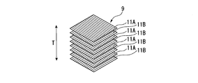
- the moving blade 6 has a core material 8, a fiber laminate 9 covering the core material 8, and a resin 10 which impregnates the fiber laminate 9 to form the outer shape of the moving blade 6. doing.
- the fiber laminate 9 is formed by laminating a plurality of fiber sheets 11, and is disposed such that the fiber sheet 11 and the surface of the core material 8 are in surface contact.
- the core material 8 is disposed at the center of the blade thickness direction T of the moving blade 6.
- the fiber direction of the fiber sheet 11 constituting the fiber laminate 9 is defined.
- prescribed one direction D is defined as 0 degree direction fiber sheet 11A.
- a fiber sheet 11 in which carbon fibers extend in a direction intersecting with the carbon fibers of the 0 ° direction fiber sheet 11A at an angle of 90 ° is defined as a 90 ° direction fiber sheet 11B. That is, the carbon fibers of the 0 ° direction fiber sheet 11A and the carbon fibers of the 90 ° direction fiber sheet 11B are substantially orthogonal to each other.
- a fiber sheet 11 in which carbon fibers extend in a direction intersecting at an angle of 45 ° with carbon fibers of the 0 ° direction fiber sheet 11A is defined as a 45 ° direction fiber sheet 11C.
- the fiber sheet 11 in which carbon fibers extend in a direction intersecting at an angle of -45 ° with respect to the carbon fibers of the 0 ° direction fiber sheet 11A is defined as a -45 ° direction fiber sheet 11D.
- the carbon fibers of the 45 ° direction fiber sheet 11C and the carbon fibers of the -45 ° direction fiber sheet 11D are substantially orthogonal to each other.
- the compression moving blade array 5 (hereinafter referred to as the moving blade array 5) of the present embodiment includes a plurality of first moving blades 6A (base moving blades) having a first structure; And a plurality of second moving blades 6B having a second structure different from the first structure.
- the first moving blades 6A and the second moving blades 6B are alternately arranged in the circumferential direction. That is, the first moving blade 6A and the second moving blade 6B are disposed adjacent to each other in the circumferential direction.
- the first moving blade 6A and the second moving blade 6B have the same outer shape. That is, the resin 10 forming the outer shape of the first moving blade 6A and the resin 10 forming the outer shape of the second moving blade 6B have the same shape.
- FIG. 5 is a schematic view for explaining the fiber direction of the fiber sheet 11 constituting the fiber laminate 9 of the first moving blade 6A among the plurality of moving blades 6 constituting the moving blade row 5.
- the fiber laminate 9 has a plurality of 0 ° direction fiber sheets 11A and a plurality of 90 ° direction fiber sheets 11B.
- the 0 ° direction fiber sheet 11A and the 90 ° direction fiber sheet 11B are alternately stacked in the wing thickness direction T. That is, in the fiber laminate 9 of the first moving blade 6A, carbon fibers of the fiber sheet 11 adjacent in the blade thickness direction T are orthogonal to each other.
- FIG. 6 is a schematic view for explaining the fiber direction of the fiber sheet 11 constituting the fiber laminate 9 of the second moving blade 6B among the plurality of moving blades 6 constituting the moving blade row 5.
- the fiber laminate 9 has a plurality of 0 ° direction fiber sheets 11A, a plurality of 90 ° direction fiber sheets 11B, and a 45 ° direction fiber sheet 11C.
- the 0 ° direction fiber sheet 11A and the 90 ° direction fiber sheet 11B are alternately laminated, and any of the fiber sheets 11 is changed to a 45 ° direction fiber sheet 11C.
- the fiber laminate 9 of the second moving blade 6B has the 45 ° -direction fiber sheet 11C, so that the first moving blade 6A and the second moving blade 6B have a structure in which the respective fiber laminates 9 are different from each other. Since the first moving blades 6A and the second moving blades 6B have different structures, the natural frequency of the first moving blades 6A and the natural frequency of the second moving blades 6B are different. That is, since the natural frequencies of the moving blades 6 constituting the moving blade row 5 have variations, the moving blade row 5 is in a so-called mistune state.
- the moving blades 6 are excited by the air flowing around the moving blades 6 and generate vibrational stress. Since the moving blades 6 are arranged at equal intervals in the circumferential direction, the excitation modes are equally spaced in the circumferential direction. On the other hand, in the plurality of moving blades 6 constituting the moving blade row 5 of this embodiment, since the moving blades 6 having different natural frequencies are alternately arranged, the vibration modes of the moving blade row 5 are equally spaced in the circumferential direction do not become. According to the above-described embodiment, since the vibration mode of the moving blade row 5 and the excitation mode for exciting the moving blade 6 do not coincide with each other, the vibration stress of the moving blade row 5 can be reduced.
- the natural frequencies of the moving blades 6 can be made different while making the shapes of the plurality of moving blades 6 the same, the vibration stress of the moving blade row 5 is reduced without affecting the aerodynamic performance. Can. Further, by making the fiber directions different, the shapes can be easily made the same by making the structures of the first moving blade 6A and the second moving blade 6B different.
- the second moving blade 6B of the above embodiment having a structure different from the structure of the first moving blade 6A which is the base wing is a 0 ° direction fiber sheet 11A, a 90 ° direction fiber sheet 11B, and a 45 ° direction fiber sheet 11C.
- it is comprised by three types of fiber sheet 11, it does not restrict to this.
- the 90 ° direction fiber sheet 11B, and the 45 ° direction fiber sheet 11C it may have a ⁇ 45 ° direction fiber sheet 11D.
- the ratio of the 0 ° direction fiber sheet 11A, the 90 ° direction fiber sheet 11B, the 45 ° direction fiber sheet 11C, and the -45 ° direction fiber sheet 11D can be appropriately changed.
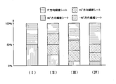
- the change of the natural frequency of the fiber laminated body 9 by changing the ratio of the fiber sheet 11 is demonstrated using four types of fiber laminated body 9.
- FIG. FIG. 7 is a graph for explaining the ratio of the fiber sheets 11 constituting the four types of fiber laminates 9.
- the first fiber laminate 9 (I) of the four types of fiber laminates 9 is a fiber laminate composed of a 0 ° direction fiber sheet 11A and a 90 ° direction fiber sheet 11B as shown in FIG. 9 These ratios are 50:50 in order of 0 degree direction fiber sheet 11A and 90 degree direction fiber sheet 11B.
- the first fiber laminate 9 does not have the 45 ° direction fiber sheet 11C and the -45 ° direction fiber sheet 11D (hereinafter, referred to as ⁇ 45 ° direction fiber sheet).
- the second fiber laminate 9 (II) is a fiber laminate 9 composed of 0 ° direction fiber sheet 11A, 45 ° direction fiber sheet 11C, -45 ° direction fiber sheet 11D, and 90 ° direction fiber sheet 11B. These ratios are 25: 25: 25: 25 in the order of 0 ° direction fiber sheet 11A, 45 ° direction fiber sheet 11C, ⁇ 45 ° direction fiber sheet 11D, and 90 ° direction fiber sheet 11B. That is, the second fiber laminate 9 (II) has the 0 ° direction fiber sheet 11A, the 45 ° direction fiber sheet 11C, the ⁇ 45 ° direction fiber sheet 11D, and the 90 ° direction fiber sheet 11B in the same ratio. The ratio of ⁇ 45 ° fiber sheet is 50%.
- the third fiber laminate 9 (III) is, similarly to the second fiber laminate 9 (II), a 0 ° direction fiber sheet 11A, a 45 ° direction fiber sheet 11C, a ⁇ 45 ° direction fiber sheet 11D, 90 °
- the fiber laminate 9 is composed of the direction fiber sheet 11B, and the ratio of these is 0 ° direction fiber sheet 11A, 45 ° direction fiber sheet 11C, -45 ° direction fiber sheet 11D, 90 ° direction fiber sheet 11B In the order of 40: 25: 25: 10. That is, in the third fiber laminate 9 (III), the ratio of the ⁇ 45 ° direction fiber sheet is 50%.
- the fourth fiber laminate 9 (IV) is, similarly to the second fiber laminate 9 (II), a 0 ° direction fiber sheet 11A, a 45 ° direction fiber sheet 11C, a ⁇ 45 ° direction fiber sheet 11D, 90 °
- the fiber laminate 9 is composed of the direction fiber sheet 11B, and the ratio of these is 0 ° direction fiber sheet 11A, 45 ° direction fiber sheet 11C, -45 ° direction fiber sheet 11D, 90 ° direction fiber sheet 11B In the order of 70: 10: 10: 10. That is, in the fourth fiber laminate 9 (IV), the ratio of ⁇ 45 ° direction fiber sheets is 20%.
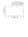
- FIG. 8 is a graph showing a change in frequency of T1 mode (torsion mode) of four types of fiber laminates 9.
- the horizontal axis in FIG. 8 is the ratio of the ⁇ 45 ° direction fiber sheet in the fiber laminate 9, and the vertical axis is based on the first fiber laminate 9 (I) in which the ⁇ 45 ° direction fiber sheet is 0%.
- Frequency change of the T1 mode As shown in FIG. 8, the frequency of the T1 mode can be changed by changing the ratio of the fiber sheet 11.
- FIG. 9 is a graph showing the frequency change of the B1 mode (bending mode in the blade height direction) of the four types of fiber laminates 9.
- the horizontal axis in FIG. 9 is the ratio of the ⁇ 45 ° direction fiber sheet in the fiber laminate 9, and the vertical axis is based on the first fiber laminate 9 (I) in which the ⁇ 45 ° direction fiber sheet is 0%. It is the frequency change of the B1 mode. As shown in FIG. 9, by changing the ratio of the fiber sheet 11, the frequency of B1 mode can be changed.
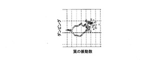
- FIG. 10 is a graph in which diameter modes (traveling waves and receding waves) of each node of the wing are plotted for the number of wings, with the horizontal axis representing the blade frequency and the vertical axis representing damping (aerodynamic damping).
- FIG. 10A is a graph of a tune system in which there is no variation in the blade frequency.
- FIG. 10B is a graph in which the variation of the frequency of the wing is medium (the standard deviation of the natural frequency of the single wing is 1%).
- FIG. 10C is a graph of a random mistuning system in which the variation of the blade frequency is large (the standard deviation of the natural frequency of a single blade is 3%).
- the aerodynamic damping can be averaged by giving variation to the frequency of the wing as a mistune system as shown in FIGS. 10B and 10C. That is, in the case of the mistune system as shown in FIG. 10B and FIG. 10C, (1) the frequency is broken in distribution, and the distribution in the horizontal axis direction of the graph is dispersed, resulting in (2) unstable damping. What was (damping 0 or less) becomes damping 0 or more and becomes stable. That is, by setting it as a mistune system, while being able to average aerodynamic damping, aerodynamic damping can be enlarged. As a result, it is possible to reduce the vibration in which the aerodynamic damping is small and the forced vibration response is large.
- the second moving blade 6B is configured such that the fiber sheet 11 of either the 0 ° direction fiber sheet 11A or the 90 ° direction fiber sheet 11B stacked alternately is changed to the 45 ° direction fiber sheet 11C.
- the fiber angle of a part of at least one fiber sheet 11 of the 0 ° direction fiber sheet 11A and the 90 ° direction fiber sheet 11B stacked alternately may be changed.
- the said embodiment it is the structure by which the 0 degree direction fiber sheet 11A and the 90 degree direction fiber sheet 11B are laminated
- the number of fiber sheets 11 to be changed to the 45 ° direction fiber sheet 11C is not limited to one, and may be one or more.
- the 1st moving blade 6A and the 2nd moving blade 6B were alternately arranged in the circumferential direction, it does not restrict to this, When the rotor 3 is seen from an axial direction, the area
- the fiber which comprises the fiber sheet 11 was used as the carbon fiber, it does not restrict to this.
- the fibers constituting the fiber sheet 11 may be glass fibers, aramid fibers, ceramic fibers, or alumina fibers.
- FIG. 12 is a schematic view illustrating the fiber direction of the fiber sheet 11 constituting the fiber laminate 9B of the second moving blade 6B (see FIG. 2) among the plurality of moving blades constituting the moving blade row.
- the fiber laminate 9B of the present embodiment includes a plurality of 0 ° direction fiber sheets 11A, a plurality of 90 ° direction fiber sheets 11B, and 0 ° direction fiber sheets 11E different in fiber type.
- the 0 ° direction fiber sheet 11A and the 90 ° direction fiber sheet 11B can be formed of PAN (polyacrylonitrile) carbon fibers
- the 0 ° direction fiber sheets 11E having different fiber types can be formed of pitch carbon fibers.
- the structures of the first moving blade 6A and the second moving blade 6B can be made different without changing the fiber direction.
- the second moving blades 6B are formed by alternately stacking the 0 ° direction fiber sheet 11A and the 90 ° direction fiber sheet 11B.
- the fiber type of a part of at least one fiber sheet 11 of the 0 ° direction fiber sheet 11A and the 90 ° direction fiber sheet 11B stacked alternately may be changed.
- the fiber sheet 11 of either the 0 ° direction fiber sheet 11A or the 90 ° direction fiber sheet 11B stacked alternately is changed to a fiber sheet having a different fiber diameter.
- the fiber laminate 9 includes a plurality of 0 ° direction fiber sheets 11A, a plurality of 90 ° direction fiber sheets 11B, and 0 ° direction fiber sheets having different fiber diameters.
- the fiber diameter of the carbon fiber of 0 ° direction fiber sheet 11A and 90 ° direction fiber sheet 11B is 5 ⁇ m
- the fiber diameter of carbon fiber of 0 ° direction fiber sheet having different fiber diameter is 10 ⁇ m.
- the structures of the first moving blade 6A and the second moving blade 6B can be made different without changing the fiber direction.
- the fiber sheet 11 of either the 0 ° direction fiber sheet 11A or the 90 ° direction fiber sheet 11B stacked alternately is changed to a fiber sheet having a different fiber diameter.
- the fiber diameter of a part of at least one fiber sheet 11 of 0 ° direction fiber sheet 11A and 90 ° direction fiber sheet 11B stacked alternately may be changed.
- FIG. 13 is a front view of the compressor 1 having the moving blade row 5D of the present embodiment.
- the moving blade row 5D of the present embodiment has a structure in which separation of carbon fibers is easily generated only in a specific moving blade 6.
- the second moving blade 6D of the moving blade row 5 of the present embodiment makes the direction of stress generation generated by the flutter mode the same as the fiber direction of the carbon fiber . Accordingly, the second moving blade 6D has a structure in which the carbon fiber is easily peeled off when the vibration exceeding the assumption occurs.
- the first moving blade 6C has a normal configuration in which the frequency does not change even when the vibration exceeding the assumption occurs.
- the frequency is increased by making it easy to cause the peeling of the carbon fiber of only the second moving blade 6D which is the specific moving blade 6 Changes greatly.
- the degree of mistuning increases, and large flutter occurs on some of the moving blades 6.
- peeling of the carbon fiber occurs, but since this peeling can be easily detected, a defect can be detected early.
- it is possible to prevent fatal damage for example, a situation in which the wing scatters from the base and collides with the wing of the rear stage to damage a large number of wings and casings.
- the structure of the fiber laminate 9 is different from that of the moving blades 6 in the moving blade row 5, but the present invention is not limited to this.
- the structure of 9 may be different.
- the fiber direction of one fiber sheet 11 is made different, and the fiber type of the other fiber sheet 11 is made different, etc. It is also good.
Landscapes
- Engineering & Computer Science (AREA)
- Mechanical Engineering (AREA)
- General Engineering & Computer Science (AREA)
- Chemical & Material Sciences (AREA)
- Materials Engineering (AREA)
- Architecture (AREA)
- Composite Materials (AREA)
- Structures Of Non-Positive Displacement Pumps (AREA)
- Turbine Rotor Nozzle Sealing (AREA)
- Laminated Bodies (AREA)
Priority Applications (4)
| Application Number | Priority Date | Filing Date | Title |
|---|---|---|---|
| KR1020207014663A KR102477730B1 (ko) | 2017-12-15 | 2018-12-14 | 회전 기계 |
| DE112018006390.9T DE112018006390T5 (de) | 2017-12-15 | 2018-12-14 | Rotationsmaschine |
| CN201880075828.XA CN111386401A (zh) | 2017-12-15 | 2018-12-14 | 旋转机械 |
| US16/767,348 US20200400038A1 (en) | 2017-12-15 | 2018-12-14 | Rotary machine |
Applications Claiming Priority (2)
| Application Number | Priority Date | Filing Date | Title |
|---|---|---|---|
| JP2017240975A JP2019108822A (ja) | 2017-12-15 | 2017-12-15 | 回転機械 |
| JP2017-240975 | 2017-12-15 |
Publications (1)
| Publication Number | Publication Date |
|---|---|
| WO2019117290A1 true WO2019117290A1 (ja) | 2019-06-20 |
Family
ID=66820454
Family Applications (1)
| Application Number | Title | Priority Date | Filing Date |
|---|---|---|---|
| PCT/JP2018/046117 Ceased WO2019117290A1 (ja) | 2017-12-15 | 2018-12-14 | 回転機械 |
Country Status (6)
| Country | Link |
|---|---|
| US (1) | US20200400038A1 (https=) |
| JP (2) | JP2019108822A (https=) |
| KR (1) | KR102477730B1 (https=) |
| CN (1) | CN111386401A (https=) |
| DE (1) | DE112018006390T5 (https=) |
| WO (1) | WO2019117290A1 (https=) |
Families Citing this family (2)
| Publication number | Priority date | Publication date | Assignee | Title |
|---|---|---|---|---|
| JP2019108822A (ja) * | 2017-12-15 | 2019-07-04 | 三菱日立パワーシステムズ株式会社 | 回転機械 |
| CN111779705B (zh) * | 2020-07-23 | 2021-06-08 | 吉林大学 | 一种基于仿生铺排结构的纤维复合材料风扇叶片 |
Citations (4)
| Publication number | Priority date | Publication date | Assignee | Title |
|---|---|---|---|---|
| JP2007270842A (ja) * | 2006-03-31 | 2007-10-18 | General Electric Co <Ge> | タービンバケット内の応力を低減するための方法及びタービンブレード |
| JP2009023163A (ja) * | 2007-07-18 | 2009-02-05 | Toyota Motor Corp | 繊維強化樹脂面材 |
| JP2009286284A (ja) * | 2008-05-29 | 2009-12-10 | Mitsubishi Heavy Ind Ltd | 船舶用プロペラの翼構造 |
| JP2013231402A (ja) * | 2012-05-01 | 2013-11-14 | Ihi Corp | 動翼及びファン |
Family Cites Families (4)
| Publication number | Priority date | Publication date | Assignee | Title |
|---|---|---|---|---|
| JPH09217601A (ja) * | 1996-02-13 | 1997-08-19 | Ishikawajima Harima Heavy Ind Co Ltd | 繊維強化複合材製翼車 |
| JP4100005B2 (ja) * | 2002-03-01 | 2008-06-11 | 株式会社Ihi | ジェットエンジン用翼と翼部の製造方法 |
| FR2869069B1 (fr) * | 2004-04-20 | 2008-11-21 | Snecma Moteurs Sa | Procede pour introduire un desaccordage volontaire sur une roue aubagee de turbomachine roue aubagee presentant un desaccordage volontaire |
| JP2019108822A (ja) * | 2017-12-15 | 2019-07-04 | 三菱日立パワーシステムズ株式会社 | 回転機械 |
-
2017
- 2017-12-15 JP JP2017240975A patent/JP2019108822A/ja active Pending
-
2018
- 2018-12-14 DE DE112018006390.9T patent/DE112018006390T5/de active Pending
- 2018-12-14 KR KR1020207014663A patent/KR102477730B1/ko active Active
- 2018-12-14 CN CN201880075828.XA patent/CN111386401A/zh active Pending
- 2018-12-14 WO PCT/JP2018/046117 patent/WO2019117290A1/ja not_active Ceased
- 2018-12-14 US US16/767,348 patent/US20200400038A1/en not_active Abandoned
-
2022
- 2022-08-05 JP JP2022125285A patent/JP2022159395A/ja active Pending
Patent Citations (4)
| Publication number | Priority date | Publication date | Assignee | Title |
|---|---|---|---|---|
| JP2007270842A (ja) * | 2006-03-31 | 2007-10-18 | General Electric Co <Ge> | タービンバケット内の応力を低減するための方法及びタービンブレード |
| JP2009023163A (ja) * | 2007-07-18 | 2009-02-05 | Toyota Motor Corp | 繊維強化樹脂面材 |
| JP2009286284A (ja) * | 2008-05-29 | 2009-12-10 | Mitsubishi Heavy Ind Ltd | 船舶用プロペラの翼構造 |
| JP2013231402A (ja) * | 2012-05-01 | 2013-11-14 | Ihi Corp | 動翼及びファン |
Also Published As
| Publication number | Publication date |
|---|---|
| CN111386401A (zh) | 2020-07-07 |
| US20200400038A1 (en) | 2020-12-24 |
| JP2019108822A (ja) | 2019-07-04 |
| KR20200072537A (ko) | 2020-06-22 |
| JP2022159395A (ja) | 2022-10-17 |
| KR102477730B1 (ko) | 2022-12-14 |
| DE112018006390T5 (de) | 2020-08-27 |
Similar Documents
| Publication | Publication Date | Title |
|---|---|---|
| US7090463B2 (en) | Guide vane | |
| US20080304972A1 (en) | Rotary body for turbo machinery with mistuned blades | |
| US11220913B2 (en) | Gas turbine engine blades with airfoil plugs for selected tuning | |
| US10294965B2 (en) | Compression system for a turbine engine | |
| EP2657449B1 (en) | Resistive band for turbomachine blade | |
| WO2019188780A1 (ja) | タービン翼及びタービン並びにタービン翼の固有振動数のチューニング方法 | |
| JP5281828B2 (ja) | ターボ機械のシャフトのための減衰装置 | |
| CA2836047C (en) | Gas turbine engine | |
| JP2022159395A (ja) | 回転機械 | |
| US10982547B2 (en) | Compressor having reinforcing disk, and gas turbine having same | |
| US7931443B1 (en) | High twist composite blade | |
| CN107061014A (zh) | 具有冲击板的飞行器发动机 | |
| CN114127387B (zh) | 鼓风机轮叶 | |
| JP6192419B2 (ja) | プロペラファン | |
| US11136889B2 (en) | Compressor blade having organic vibration stiffener | |
| US10641112B2 (en) | Bladed disk | |
| JP6367525B2 (ja) | 湾曲装着形状のブレードセグメントを有するシステム | |
| US11560801B1 (en) | Fan blade with internal magnetorheological fluid damping | |
| JP2015197082A (ja) | 動翼及び回転機械 | |
| US11242771B2 (en) | Gas turbine rotor having structure for adjusting axial clearance, and gas turbine having same | |
| US20230203952A1 (en) | Fan blade with internal shear-thickening fluid damping | |
| US20230134727A1 (en) | Fan rotor for airfoil damping | |
| JP2003214107A (ja) | 軸流タービン翼およびこれを使用したガスタービン、並びに軸流圧縮機 | |
| JP2022063258A (ja) | デュアル部分スパンシュラウドおよび空気力学的特徴部を備えたタービンバケット | |
| US20200291786A1 (en) | Aerofoil for gas turbine incorporating one or more encapsulated void |
Legal Events
| Date | Code | Title | Description |
|---|---|---|---|
| 121 | Ep: the epo has been informed by wipo that ep was designated in this application |
Ref document number: 18887427 Country of ref document: EP Kind code of ref document: A1 |
|
| ENP | Entry into the national phase |
Ref document number: 20207014663 Country of ref document: KR Kind code of ref document: A |
|
| 122 | Ep: pct application non-entry in european phase |
Ref document number: 18887427 Country of ref document: EP Kind code of ref document: A1 |