WO2019107369A1 - Injecteur de carburant, chambre de combustion et turbine à gaz - Google Patents
Injecteur de carburant, chambre de combustion et turbine à gaz Download PDFInfo
- Publication number
- WO2019107369A1 WO2019107369A1 PCT/JP2018/043634 JP2018043634W WO2019107369A1 WO 2019107369 A1 WO2019107369 A1 WO 2019107369A1 JP 2018043634 W JP2018043634 W JP 2018043634W WO 2019107369 A1 WO2019107369 A1 WO 2019107369A1
- Authority
- WO
- WIPO (PCT)
- Prior art keywords
- plate
- cooling
- air
- upstream
- downstream
- Prior art date
Links
Images


Classifications
-
- F—MECHANICAL ENGINEERING; LIGHTING; HEATING; WEAPONS; BLASTING
- F23—COMBUSTION APPARATUS; COMBUSTION PROCESSES
- F23R—GENERATING COMBUSTION PRODUCTS OF HIGH PRESSURE OR HIGH VELOCITY, e.g. GAS-TURBINE COMBUSTION CHAMBERS
- F23R3/00—Continuous combustion chambers using liquid or gaseous fuel
- F23R3/28—Continuous combustion chambers using liquid or gaseous fuel characterised by the fuel supply
- F23R3/283—Attaching or cooling of fuel injecting means including supports for fuel injectors, stems, or lances
-
- F—MECHANICAL ENGINEERING; LIGHTING; HEATING; WEAPONS; BLASTING
- F02—COMBUSTION ENGINES; HOT-GAS OR COMBUSTION-PRODUCT ENGINE PLANTS
- F02C—GAS-TURBINE PLANTS; AIR INTAKES FOR JET-PROPULSION PLANTS; CONTROLLING FUEL SUPPLY IN AIR-BREATHING JET-PROPULSION PLANTS
- F02C7/00—Features, components parts, details or accessories, not provided for in, or of interest apart form groups F02C1/00 - F02C6/00; Air intakes for jet-propulsion plants
- F02C7/12—Cooling of plants
- F02C7/16—Cooling of plants characterised by cooling medium
- F02C7/18—Cooling of plants characterised by cooling medium the medium being gaseous, e.g. air
-
- F—MECHANICAL ENGINEERING; LIGHTING; HEATING; WEAPONS; BLASTING
- F02—COMBUSTION ENGINES; HOT-GAS OR COMBUSTION-PRODUCT ENGINE PLANTS
- F02C—GAS-TURBINE PLANTS; AIR INTAKES FOR JET-PROPULSION PLANTS; CONTROLLING FUEL SUPPLY IN AIR-BREATHING JET-PROPULSION PLANTS
- F02C7/00—Features, components parts, details or accessories, not provided for in, or of interest apart form groups F02C1/00 - F02C6/00; Air intakes for jet-propulsion plants
- F02C7/22—Fuel supply systems
-
- F—MECHANICAL ENGINEERING; LIGHTING; HEATING; WEAPONS; BLASTING
- F23—COMBUSTION APPARATUS; COMBUSTION PROCESSES
- F23R—GENERATING COMBUSTION PRODUCTS OF HIGH PRESSURE OR HIGH VELOCITY, e.g. GAS-TURBINE COMBUSTION CHAMBERS
- F23R3/00—Continuous combustion chambers using liquid or gaseous fuel
- F23R3/28—Continuous combustion chambers using liquid or gaseous fuel characterised by the fuel supply
- F23R3/286—Continuous combustion chambers using liquid or gaseous fuel characterised by the fuel supply having fuel-air premixing devices
-
- F—MECHANICAL ENGINEERING; LIGHTING; HEATING; WEAPONS; BLASTING
- F05—INDEXING SCHEMES RELATING TO ENGINES OR PUMPS IN VARIOUS SUBCLASSES OF CLASSES F01-F04
- F05D—INDEXING SCHEME FOR ASPECTS RELATING TO NON-POSITIVE-DISPLACEMENT MACHINES OR ENGINES, GAS-TURBINES OR JET-PROPULSION PLANTS
- F05D2220/00—Application
- F05D2220/30—Application in turbines
- F05D2220/32—Application in turbines in gas turbines
-
- F—MECHANICAL ENGINEERING; LIGHTING; HEATING; WEAPONS; BLASTING
- F05—INDEXING SCHEMES RELATING TO ENGINES OR PUMPS IN VARIOUS SUBCLASSES OF CLASSES F01-F04
- F05D—INDEXING SCHEME FOR ASPECTS RELATING TO NON-POSITIVE-DISPLACEMENT MACHINES OR ENGINES, GAS-TURBINES OR JET-PROPULSION PLANTS
- F05D2240/00—Components
- F05D2240/35—Combustors or associated equipment
-
- F—MECHANICAL ENGINEERING; LIGHTING; HEATING; WEAPONS; BLASTING
- F23—COMBUSTION APPARATUS; COMBUSTION PROCESSES
- F23R—GENERATING COMBUSTION PRODUCTS OF HIGH PRESSURE OR HIGH VELOCITY, e.g. GAS-TURBINE COMBUSTION CHAMBERS
- F23R2900/00—Special features of, or arrangements for continuous combustion chambers; Combustion processes therefor
- F23R2900/03282—High speed injection of air and/or fuel inducing internal recirculation
Definitions
- the present invention relates to a fuel injector, a combustor, and a gas turbine.
- the combustor of the gas turbine has a fuel injector.
- the fuel injector mixes the compressed air and the fuel gas uniformly in advance.
- the combustor then produces a high temperature combustion gas.
- a combustor of a gas turbine one having stable combustion and low emissions of CO and NOx, which are environmentally harmful substances, is preferable.
- a porous jet burner also referred to as a "coulaster burner”
- Patent Document 1 one equipped with a porous jet burner (also referred to as a "coulaster burner") is known (see, for example, Patent Document 1).
- Patent Document 1 an upstream plate disposed upstream and having a plurality of air holes formed therein, a downstream plate disposed downstream of the upstream plate and having a plurality of air holes formed therein, and a fuel feed A fuel injector comprising a feed tube is disclosed.
- the present invention aims to provide a fuel injector, a combustor, and a gas turbine capable of efficiently cooling the downstream side plate.
- a fuel injector includes an upstream plate, and a downstream plate provided on the downstream side of the upstream plate and disposed opposite to the upstream plate.
- An upstream side and a downstream side of the tubular form having an open end, and the upstream side plate disposed at the upstream open end and the downstream side plate disposed at the downstream open end are internally plenums.
- a tubular member extending through the upstream plate, the downstream plate, and the plenum, the upstream side and the downstream side being open ends; And a pre-mixing channel having a fuel hole for introducing the fuel gas supplied into the plenum to the inside, and mixing the fuel gas with air introduced from the upstream open end.
- a cooling air introducing pipe for introducing cooling air to the downstream side plate including an air introducing portion into which the cooling air from the cooling air introducing pipe is introduced, and the air And a cooling channel extending away from the premixing tube in a direction along the surface of the downstream side plate from the introducing part.
- the downstream plate it is possible to directly cool the downstream side plate with the cooling air by providing the cooling flow passage through which the cooling air flows in the downstream side plate which becomes high temperature.
- the downstream plate can be efficiently cooled using a smaller amount of cooling air as compared to the case where the cooling air is blown from the outside of the downstream plate.
- the downstream side plate with the air introduction portion into which the cooling air from the cooling air introduction pipe is introduced, it is not necessary to provide the plenum for the cooling air, and it is sufficient to provide only the fuel gas plenum.
- the structure of the fuel injector can be simplified.
- the downstream plate includes a first plate portion having a first surface facing the upstream plate, and an upstream side of the first plate portion.
- the second surface may be disposed and joined to the first surface, and a second plate portion having the cooling channel.
- the cooling flow path is formed by forming the cooling flow path not in the first plate portion where the adhering flame may be formed, but in the second plate portion disposed upstream of the first plate portion. It becomes possible to reduce the thickness of the first plate portion which tends to be hotter than the plate portion 2. Thus, the thin first plate portion can be efficiently cooled using the cooling air flowing in the cooling flow path.
- the cooling flow passage may be a groove recessed from the second surface to the upstream plate side.
- a part of the cooling air flowing through the cooling flow passage can be brought into direct contact with the first surface of the first plate portion, so that the cooling flow to the second plate portion
- the first plate portion can be cooled more efficiently than in the case where the passage is internally provided.
- the first plate portion may have a through hole penetrating a portion facing the groove.
- the cylindrical member has an exhaust path for discharging the cooling air having passed through the downstream plate to the upstream side of the upstream plate. It is also good.
- the cooling air exhausted from the exhaust path can be reused as the air introduced into the premix tube.
- a burner concerning one mode of the present invention stores the above-mentioned fuel injector and the above-mentioned fuel injector, and fuel gas and air which were injected from the above-mentioned fuel injector were mixed. And b) burning the gas to produce a combustion gas.
- the downstream plate can be efficiently cooled, and the combustor can be operated stably.
- a gas turbine concerning one mode of the present invention generates the above-mentioned burner, compressed air as well as a compressor which supplies the above-mentioned compressed air as the above-mentioned air to the above-mentioned fuel injector, and the above-mentioned compression
- An air extraction unit for extracting the compressed air generated by the machine, a forced air cooling compressor for further compressing the compressed air extracted by the extraction unit to generate cooling air, and the air generated by the forced air cooling compressor
- a cooling air inlet line for introducing cooling air into the combustor.
- the downstream plate can be efficiently cooled and the gas turbine can be stably operated by including the combustor. Further, by having the forced air-cooling compressor, it is possible to further compress the compressed air extracted by the extraction unit. As a result, it is possible to supply the combustion air with cooling air that is at a higher pressure than the extracted compressed air. Furthermore, by having a forced air-cooling compressor, the cross-sectional area of the cooling channel can be reduced.
- the gas turbine which concerns on 1 aspect of this invention WHEREIN: You may provide the cooler which cools the compressed air extracted by the said extraction part.
- cooling air having a temperature lower than that of the extracted compressed air can be supplied to the combustor.
- the downstream plate can be cooled efficiently.
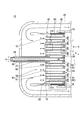
- FIG. 1 It is a figure showing a schematic structure of a gas turbine concerning an embodiment of the present invention. It is sectional drawing to which the part in which the fuel injector was arrange
- FIG. 1 A gas turbine 10 of the present embodiment will be described with reference to FIG.
- a generator 5 which is not a component of the gas turbine 10 is illustrated.
- the compressor 11, the turbine 12, the intermediate casing 13, and the combustor 15 are illustrated in cross section. Further, in FIG.
- A is compressed air (hereinafter referred to as “compressed air A”)
- Ao is outside air (hereinafter referred to as “outside air Ao")
- Ax is an axis of compressor 11 and turbine 12 (hereinafter referred to as “axis Ax” )
- CA is cooling air (hereinafter referred to as “cooling air CA”)
- F is a fuel gas (hereinafter referred to as “fuel gas F”
- G is a combustion gas (hereinafter referred to as “combusted gas G”). It shows.
- the gas turbine 10 includes a compressor 11, a turbine 12, an intermediate casing 13, a plurality of combustors 15, and a cooling device 17.
- the compressor 11 includes a compressor rotor 21, a compressor casing 23, and a plurality of compressor vane arrays 25.
- the compressor rotor 21 rotates about an axis Ax.
- the compressor rotor 21 has a compressor rotor shaft 27 and a plurality of compressor blade arrays 28.
- the compressor rotor shaft 27 extends in the direction of the axis Ax, and the axis coincides with the axis Ax.
- the plurality of compression blade arrays 28 are provided on the outer peripheral surface of the compressor rotor shaft 27.
- the plurality of compression blade arrays 28 are arranged at intervals in the direction of the axis Ax.
- the plurality of compression blade arrays 28 are constituted by a plurality of moving blades arranged in the circumferential direction of the compressor rotor shaft 27.
- external air Ao for example, air
- air taken in from the outside
- the compressed air A is generated by passing through the formed space.
- the generated compressed air A is supplied into the intermediate vehicle chamber 13.
- the compressor casing 23 is cylindrical and accommodates the compressor rotor 21.
- the plurality of compressor vane arrays 25 are fixed to the inside of the compressor casing 23.
- the compressor vane row 25 is disposed on the downstream side of each compression blade row 28.
- the plurality of compressor stator blade rows 25 are each configured by a plurality of stator blades arranged in the circumferential direction of the compressor casing 23.
- the turbine 12 has a turbine rotor 31, a turbine casing 33, and a plurality of turbine vane arrays 35.
- the turbine rotor 31 has a turbine rotor shaft 37 and a plurality of turbine moving blade cascades 38.
- the turbine rotor shaft 37 extends in the direction of the axis Ax and rotates around the axis Ax.
- One end of the turbine rotor shaft 37 is connected to the rotor of the generator 5.
- the plurality of turbine moving blade cascades 38 are provided on the outer peripheral surface of the turbine rotor shaft 37.
- the plurality of turbine blade arrays 38 are arranged at intervals in the direction of the axis Ax.
- the plurality of turbine moving blade cascades 38 are configured by a plurality of moving blades arranged in the circumferential direction of the turbine rotor shaft 37 respectively.
- the turbine rotor 31 configured as described above is connected to the compressor rotor 21 described above in the direction of the axis Ax. Thereby, the turbine rotor 31 and the compressor rotor 21 rotate integrally.
- the turbine rotor 31 and the compressor rotor 21 constitute a gas turbine rotor 42.
- the turbine casing 33 is cylindrical and accommodates the turbine rotor 31.
- the plurality of turbine vane arrays 35 are provided inside the turbine casing 33.
- the turbine stator blade row 35 is disposed upstream of each turbine blade row 38.
- the plurality of turbine vane arrays 35 are configured by a plurality of vanes arranged in the circumferential direction of the turbine casing 33 respectively.
- generated by the combustor 15 mentioned later is supplied to the turbine 12 set as the said structure. Then, the combustion gas G passes through the space formed between the turbine stator blade row 35 and the turbine moving blade row 38, whereby the turbine rotor shaft 37 is rotationally driven. Thus, rotational power is applied to the generator 5 connected to the gas turbine rotor 42, and power generation is performed.
- the intermediate casing 13 is provided between the compressor casing 23 and the turbine casing 33.
- the intermediate casing 13 is a cylindrical member extending in the direction of the axis Ax. The end on the upstream side in the axis line Ax direction of the intermediate casing 13 is connected to the compressor casing 23. The end on the downstream side in the axis line Ax direction of the intermediate casing 13 is connected to the turbine casing 33.
- I, J, and M indicate regions (hereinafter, referred to as “region I”, “region J”, and “region M,” respectively), and L indicates a central axis of the fuel injector 50 (hereinafter referred to as “central axis L X direction indicates the extending direction of the central axis L, respectively.
- L indicates a central axis of the fuel injector 50 (hereinafter referred to as “central axis L X direction indicates the extending direction of the central axis L, respectively.
- the arrows attached in the vicinity of the downstream side plate 59 schematically show how the mixed gas of the compressed air A and the fuel gas F is ejected.
- FIG. 3 the same components as those of the structure shown in FIG. In FIG. 4, the same components as those shown in FIGS. 2 and 3 are denoted by the same reference numerals.
- FIG. 5 the same components as those shown in FIGS. 2 and 4 are denoted by the same reference numerals.
- FIG. 6 the same components as those shown in FIGS. 2 to 4 are denoted by the same reference numerals.
- the combustor 15 has an outer cylinder 49, a fuel injector 50, a combustion cylinder 52, and a spring member 55.
- the outer cylinder 49 is a cylindrical member whose both ends are open ends.
- a plurality of outer cylinders 49 are provided in the intermediate vehicle chamber 13 in a state where a part of the outer cylinder 49 is disposed in the intermediate vehicle chamber 13.
- the plurality of outer cylinders 49 are arranged around the axis line Ax in a state of being separated from each other.
- the outer cylinder 49 burns a gas (mixed gas) in which the compressed air A injected from the fuel injector 50 and the fuel gas F are mixed, thereby generating a high temperature / high pressure combustion gas G.
- the outlet side of the outer cylinder 49 is connected to the turbine casing 33.
- the outer cylinder 49 supplies the generated combustion gas G into the turbine casing 33.
- the fuel injector 50 is accommodated in the outer cylinder 49, and the upstream plate 58, the downstream plate 59, the cylindrical member 62, the fuel tube 64, the premixing tube 65, and the cooling air introducing tube 68. And.
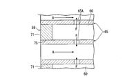
- the upstream plate 58 has a plate body 71, a fuel tube insertion hole 73, and a premix tube insertion hole 75.
- the plate main body 71 is a plate-like member, and is disposed inside the cylindrical member 62 located on the upstream side.
- the outer peripheral surface of the plate main body 71 is connected to the inner peripheral surface of the cylindrical member 62.
- a circular metal plate can be used as the plate main body 71.
- the fuel tube insertion hole 73 is formed to penetrate the central portion of the plate main body 71 in the X direction.
- the fuel tube insertion hole 73 is a hole into which the tip of the fuel tube 64 is inserted.
- a plurality of premixing tube insertion holes 75 are provided in the plate body 71 located outside the fuel tube insertion hole 73.
- the premix tube insertion hole 75 penetrates the plate body 71 in the X direction.
- the premix tube insertion hole 75 is a hole into which the upstream end of the premix tube 65 is inserted. Compressed air A is introduced into the premix tube insertion hole 75 with the upstream end of the premix tube 65 inserted.
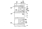
- the downstream side plate 59 is disposed inside the cylindrical member 62 located on the downstream side of the upstream side plate 58, and defines the plenum 60 together with the upstream side plate 58 and the cylindrical member 62.
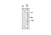
- the downstream side plate 59 has a first plate portion 83, a second plate portion 84, a premixing tube insertion hole 85, an air introducing portion 86, a distributing portion 88, and a cooling channel 91.
- the first plate portion 83 is a plate-like member, and is disposed inside the cylindrical member 62 located on the downstream side of the upstream plate 58.
- the outer peripheral surface of the first plate portion 83 is connected to the inner peripheral surface of the cylindrical member 62.
- the first plate portion 83 has a first surface 83 a facing the upstream plate 58 in the X direction, and a surface 83 b disposed on the opposite side of the first surface 83 a.
- the surface 83 b of the first plate portion 83 is a surface on which the adhesion flame may be generated. For this reason, the surface 83b side of the first plate portion 83 tends to have a higher temperature than the first surface 83a side.
- a circular metal plate can be used as the first plate portion 83.
- the second plate portion 84 is a plate-like member, and is provided inside the cylindrical member 62 located on the upstream side of the first plate portion 83.
- the second plate portion 84 is arranged to be in contact with the first surface 83a.
- the second plate portion 84 is joined to the first surface 83a.
- the second plate portion 84 has a second surface 84 a joined to the first surface 83 a and a surface 84 b disposed on the opposite side of the second surface 84 a.
- the surface 84b defines the end of the plenum 60 located downstream in the X direction.
- the first plate portion 83 is disposed downstream of the second plate portion 84. Therefore, the temperature of the second plate portion 84 is lower than the temperature of the first plate portion 83.
- a plurality of premix tube insertion holes 85 are formed to penetrate the first and second plate portions 83 and 84 in the X direction.
- the plurality of premix tube insertion holes 85 are disposed at positions opposed to one premix tube insertion hole 75 disposed in the X direction.
- the premix tube insertion hole 85 is a hole into which the downstream end of the premix tube 65 is inserted.
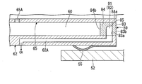
- the air introduction portion 86 is a recess formed in the second plate portion 84 from the second surface 84 a side, and is connected to the downstream end of the cooling air introduction pipe 68.
- the air introduction unit 86 is connected to the distribution unit 88 provided in each sector 90.
- the air introduction portion 86 configured in this way, it is not necessary to provide a plenum for cooling air, and only the plenum 60 for fuel gas may be provided, so the structure of the fuel injector 50 is simplified. It can be done.
- the distributing portion 88 is a recess formed in the second plate portion 84 from the second surface 84 a side, and is in communication with the plurality of cooling channels 91.
- the distribution unit 88 has a function of distributing the cooling air CA introduced from the cooling air introduction pipe 68 to the plurality of cooling channels 91.
- a plurality of cooling channels 91 are formed in the second plate portion 84.
- As the cooling channel 91 for example, it is possible to use a groove 92 recessed from the second surface 84a to the upstream plate 58 side.
- the cooling air CA distributed by the distributing unit 88 flows through the cooling flow passage 91.
- the cooling air CA flowing through the cooling flow passage 91 is air for cooling the first and second plate portions 83 and 84.
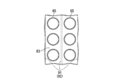
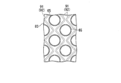
- the cooling channels 91 are arranged to extend in a direction along the surface (first surface 83 a) of the downstream side plate 59 so as to avoid the premixing tube 65.
- “extending avoiding the premixing tube 65” means, as shown in FIG. 7 and FIG. 8, a case where the cooling flow passage 91 is disposed linearly to avoid the premixing tube 65 or Including the case where the cooling channel 91 is disposed in the zigzag to avoid the premix tube 65, and the like.
- FIGS. 7 and 8 the same components as those of the structure shown in FIG.
- the downstream plate 59 can be directly cooled by the cooling air CA.
- the downstream plate 59 can be efficiently cooled using a smaller amount of the cooling air CA, as compared to the case where the cooling air CA is sprayed from the outside of the downstream plate 59.
- the cooling flow passage 91 in the second plate portion 84 disposed upstream of the first plate portion 83, not in the first plate portion 83 where the adhering flame may be formed. It is possible to reduce the thickness of the first plate portion 83 which is likely to be hotter than the second plate portion 84. Thereby, the thin first plate portion 83 can be efficiently cooled using the cooling air CA flowing in the cooling flow passage 91.
- the cooling flow passage 91 By using a groove 92 recessed from the second surface 84 a toward the upstream plate 58 as the cooling flow passage 91, a portion of the cooling air CA flowing through the cooling flow passage 91 can be made of the first plate portion 83. Since it is possible to make direct contact with the first surface 83 a, the first plate portion 83 can be efficiently cooled compared to the case where the cooling flow passage 91 is provided in the second plate portion 84. Can.
- the cylindrical member 62 is a cylindrical metal member whose upstream and downstream sides in the X direction are open ends.
- the tubular member 62 is a member for accommodating the first and second plate portions 83 and 84 and for partitioning the plenum 60 together with the first and second plate portions 83 and 84.
- the cylindrical member 62 is connected to the cooling flow passage 91 formed in the downstream side plate 59, and the space in the outer cylinder formed with the cooling air CA drawn from the cooling flow passage 91 on the upstream side of the upstream side plate 58 An exhaust path 62A for exhausting air.
- the cooling air CA exhausted from the exhaust path 62A can be reused as the air introduced into the premixing tube 65.
- the fuel tube 64 extends in the X direction, and is joined to the upstream plate 58 in a state in which the tip end portion is inserted into the fuel tube insertion hole 73.
- the fuel tube 64 supplies fuel gas to the plenum 60.
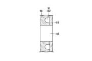
- the premixing tube 65 is a tubular tube whose upstream and downstream sides are open ends.
- the premixing tube 65 is provided to penetrate the upstream plate 58, the downstream plate 59, and the plenum 60 in the X direction.
- the upstream end of the premixing tube 65 is disposed in the premixing tube insertion hole 75 and is joined to a plate main body 71 that defines the premixing tube insertion hole 75.
- the downstream end of the premixing tube 65 is disposed in the premixing tube insertion hole 85, and is joined to first and second plate portions 83 and 84 that define the premixing tube insertion hole 85.
- the premixing tube 65 has fuel holes 65A for guiding the fuel gas F introduced into the plenum 60 into the premixing tube 65.
- the fuel gas F introduced into the premixing tube 65 from the fuel holes 65A is mixed with the compressed air A in the premixing tube 65.
- the cooling air introduction pipe 68 is disposed in the fuel tube 64 and in the plenum 60 with the downstream end connected to the second plate portion 84.
- the cooling air inlet pipe 68 introduces the cooling air CA into the air inlet 86.
- the downstream plate 59 can be directly cooled by the cooling air CA. Become.
- the downstream plate 59 can be efficiently cooled using a smaller amount of the cooling air CA, as compared to the case where the cooling air CA is sprayed from the outside of the downstream plate 59.
- the downstream side plate 59 with the air introducing portion 86 into which the cooling air CA from the cooling air introducing pipe 68 is introduced, it is not necessary to provide a plenum for the cooling air, and only the fuel gas plenum 60 can be provided.
- the structure of the fuel injector 50 can be simplified because it may be provided.
- FIGS. 9 to 12 a method of forming the downstream side plate 59 and a method of joining the premix tube 65 to the downstream side plate 59 will be described.
- FIGS. 9 to 12 the same components as those shown in FIG. 4 are designated by the same reference numerals.
- the cooling flow path 91 is formed by processing the groove 92 from the second surface 84 a side of the second plate portion 84.
- the second plate portion 84 and the first plate portion 84 are in contact with the second surface 84a of the second plate portion 84 and the first surface 83a of the first plate portion 83.
- the plate portion 83 of the As a joining method for example, brazing can be used.
- a premix tube insertion hole 85 penetrating the first and second plate portions 83 and 84 is formed.
- the air introduction portion 86 and the distribution portion 88 may be formed together with the premix tube insertion hole 85 in the process shown in FIG.
- the premix tube insertion hole 85 is fixed to the downstream plate 59 by welding in a state where the downstream end of the premix tube 65 is inserted into the premix tube insertion hole 85.
- the combustion cylinder 52 is a cylindrical member, and accommodates the downstream side of the fuel injector 50 with a gap interposed.
- the spring member 55 is disposed between the outer peripheral surface of the fuel injector 50 and the inner peripheral surface of the combustion cylinder 52.
- the position of the fuel injector 50 in the outer cylinder 49 is regulated by the combustion cylinder 52 and the spring member 55.
- the cooling device 17 is a device for extracting a part of the compressed air A supplied to the combustor 15 and supplying it to the fuel injector 50 after being compressed again.
- the cooling device 17 has a bleed portion 101, a cooler 103, a forced air-cooling compressor 104, an antisurge valve 105, and a cooling air introduction line 106.
- the bleed unit 101 is provided in the intermediate vehicle room 13.
- the bleed unit 101 bleeds the compressed air A introduced into the intermediate vehicle chamber 13.
- the extracted compressed air A is supplied to the cooler 103.
- the cooler 103 cools the extracted compressed air A.
- the compressed air A cooled by the cooler 103 is supplied to a forced air-cooling compressor 104.
- the compressed air A can be cooled.
- the cooling air CA having a temperature lower than that of the extracted compressed air A can be supplied to the combustor 15.
- the forced air-cooling compressor 104 further generates the cooling air CA by further compressing the compressed air A cooled by the cooler 103.
- the cooling air CA generated by the forced air-cooling compressor 104 is led to the cooling air introduction line 106.
- the anti-surge valve 105 prevents the surge of the forced air-cooling compressor 104.
- the cooling air inlet line 106 is connected to the cooling air inlet pipe 68 shown in FIG.
- the cooling air introduction line 106 causes the cooling air introduction pipe 68 to introduce the cooling air CA.
- the cooling air CA may be supplied to another cooling target of the gas turbine 10, for example, a stator blade.
- the cooling device 17 described above includes the forced air-cooling compressor 104, the compressed air A extracted from the extraction unit 101 can be further compressed. As a result, the cooling air CA, which is at a higher pressure than the extracted compressed air A, can be supplied to the combustor 15. Moreover, by having the forced air-cooling compressor 104, the cross-sectional area of the cooling flow path 91 can be made small.
- FIG. 2 as an example, the case where one system of cooling device 17 is provided for one gas turbine 10 has been described as an example, but a plurality of systems of cooling are provided for one gas turbine 10.
- a device 17 may be provided.
- the downstream plate 59 can be efficiently cooled and the gas turbine 10 can be stably operated by including the combustor 15.
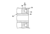
- FIG. 13 a part of the fuel injector 110 is illustrated in an enlarged state.
- the same components as those of the structure shown in FIG. 13 the same components as those of the structure shown in FIG.
- the fuel injector 110 makes the thickness of the second plate portion 84 thicker than that of the first plate portion 83, and provides the cooling flow path 91 (groove 92) in the second plate portion 84, It is comprised similarly to the fuel injector 50 of this embodiment.
- the cooling channel 91 (groove 92) may be provided in the second plate portion 84.
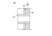
- FIG. 14 a part of the fuel injector 120 is illustrated in an enlarged state.
- the same components as in the structure shown in FIG. 14 the same components as in the structure shown in FIG. 14
- the fuel injector 120 is configured in the same manner as the fuel injector 50 of the present embodiment, except for having a through hole 111 penetrating a portion facing the groove 92 in the first plate portion 83.
- the through hole 111 configured as described above, it becomes possible to cool the first plate portion 83 from the inside of the first plate portion 83 by the cooling air CA flowing through the through hole 111 and it is possible to penetrate
- the cooling air CA discharged from the holes 111 can cool the surface 83 b of the first plate portion 83. Thereby, the 1st plate part 83 can be cooled very efficiently.
- the compressed air A compressed by the compressor 11 is supplied as the cooling air CA to the fuel injectors 50, 110, and 120 after passing through the cooling device 17 as an example.
- the compressed air A compressed by the compressor 11 may be supplied to the fuel injectors 50, 110, and 120 as the cooling air CA without passing through the cooling device 17.
- the present invention is applicable to fuel injectors, combustors, and gas turbines.
Landscapes
- Engineering & Computer Science (AREA)
- Chemical & Material Sciences (AREA)
- Combustion & Propulsion (AREA)
- Mechanical Engineering (AREA)
- General Engineering & Computer Science (AREA)
- Turbine Rotor Nozzle Sealing (AREA)
Abstract
La présente invention est pourvue d'une plaque aval (59) qui est disposée sur le côté aval d'une plaque amont (58) et comprend : une partie d'introduction d'air (86) dans laquelle de l'air de refroidissement provenant d'un tuyau d'introduction d'air de refroidissement (68) est introduit ; et un trajet d'écoulement de refroidissement (91) qui s'étend depuis la partie d'introduction d'air (86) dans une direction le long de la surface de la plaque aval (59) de façon à éviter un tube de prémélange (65) et à travers lequel l'air de refroidissement s'écoule.
Priority Applications (5)
| Application Number | Priority Date | Filing Date | Title |
|---|---|---|---|
| CN201880076080.5A CN111386429B (zh) | 2017-11-30 | 2018-11-27 | 燃料喷射器、燃烧器、以及燃气轮机 |
| KR1020207014665A KR102503321B1 (ko) | 2017-11-30 | 2018-11-27 | 연료 분사기, 연소기 및 가스 터빈 |
| KR1020227008914A KR102503322B1 (ko) | 2017-11-30 | 2018-11-27 | 연료 분사기, 연소기 및 가스 터빈 |
| US16/767,359 US11274832B2 (en) | 2017-11-30 | 2018-11-27 | Fuel injector, combustor, and gas turbine |
| DE112018006141.8T DE112018006141T5 (de) | 2017-11-30 | 2018-11-27 | Brennstoffinjektor, brennkammer und gasturbine |
Applications Claiming Priority (2)
| Application Number | Priority Date | Filing Date | Title |
|---|---|---|---|
| JP2017231143A JP6979343B2 (ja) | 2017-11-30 | 2017-11-30 | 燃料噴射器、燃焼器、及びガスタービン |
| JP2017-231143 | 2017-11-30 |
Publications (1)
| Publication Number | Publication Date |
|---|---|
| WO2019107369A1 true WO2019107369A1 (fr) | 2019-06-06 |
Family
ID=66664929
Family Applications (1)
| Application Number | Title | Priority Date | Filing Date |
|---|---|---|---|
| PCT/JP2018/043634 WO2019107369A1 (fr) | 2017-11-30 | 2018-11-27 | Injecteur de carburant, chambre de combustion et turbine à gaz |
Country Status (6)
| Country | Link |
|---|---|
| US (1) | US11274832B2 (fr) |
| JP (1) | JP6979343B2 (fr) |
| KR (2) | KR102503321B1 (fr) |
| CN (1) | CN111386429B (fr) |
| DE (1) | DE112018006141T5 (fr) |
| WO (1) | WO2019107369A1 (fr) |
Families Citing this family (8)
| Publication number | Priority date | Publication date | Assignee | Title |
|---|---|---|---|---|
| KR102426622B1 (ko) * | 2021-01-06 | 2022-07-28 | 두산에너빌리티 주식회사 | 연소기 및 이를 포함하는 가스터빈 |
| KR102403750B1 (ko) * | 2021-01-15 | 2022-05-30 | 두산에너빌리티 주식회사 | 멀티 튜브를 갖는 연소기용 노즐, 연소기, 및 이를 포함하는 가스 터빈 |
| KR102437977B1 (ko) * | 2021-01-18 | 2022-08-30 | 두산에너빌리티 주식회사 | 노즐 어셈블리, 연소기 및 이를 포함하는 가스터빈 |
| KR102460000B1 (ko) * | 2021-01-19 | 2022-10-26 | 두산에너빌리티 주식회사 | 연소기용 노즐, 연소기, 및 이를 포함하는 가스 터빈 |
| KR102429075B1 (ko) | 2021-02-17 | 2022-08-03 | 두산에너빌리티 주식회사 | 마이크로 믹서 번들 어셈블리, 이를 포함하는 연소기 및 가스 터빈 |
| KR102460001B1 (ko) * | 2021-02-17 | 2022-10-26 | 두산에너빌리티 주식회사 | 마이크로 믹서모듈 및 이를 포함하는 연소기 |
| KR102619152B1 (ko) | 2022-02-21 | 2023-12-27 | 두산에너빌리티 주식회사 | 연소기용 노즐, 연소기, 및 이를 포함하는 가스 터빈 |
| KR102599921B1 (ko) * | 2022-03-21 | 2023-11-07 | 두산에너빌리티 주식회사 | 연소기용 노즐, 연소기, 및 이를 포함하는 가스 터빈 |
Citations (8)
| Publication number | Priority date | Publication date | Assignee | Title |
|---|---|---|---|---|
| JPS6082724A (ja) * | 1983-10-13 | 1985-05-10 | Agency Of Ind Science & Technol | ガスタ−ビン燃焼器 |
| US20100031662A1 (en) * | 2008-08-05 | 2010-02-11 | General Electric Company | Turbomachine injection nozzle including a coolant delivery system |
| JP2010101309A (ja) * | 2008-10-23 | 2010-05-06 | General Electric Co <Ge> | ガスタービン燃焼器用の耐保炎性燃料/空気予混合器 |
| JP2011027402A (ja) * | 2009-07-22 | 2011-02-10 | General Electric Co <Ge> | タービンエンジンにおける燃料噴射用装置 |
| JP2013250046A (ja) * | 2012-05-30 | 2013-12-12 | General Electric Co <Ge> | タービンエンジンに使用するための燃料注入組立体及びそれを組み立てる方法 |
| JP2014088874A (ja) * | 2012-10-30 | 2014-05-15 | General Electric Co <Ge> | 燃焼器キャップアセンブリ |
| US20150076251A1 (en) * | 2013-09-19 | 2015-03-19 | General Electric Company | System for injecting fuel in a gas turbine combustor |
| US20160018109A1 (en) * | 2013-03-13 | 2016-01-21 | Siemens Aktiengesellschaft | Jet burner with cooling duct in the base plate |
Family Cites Families (19)
| Publication number | Priority date | Publication date | Assignee | Title |
|---|---|---|---|---|
| US8794545B2 (en) | 2009-09-25 | 2014-08-05 | General Electric Company | Internal baffling for fuel injector |
| US8955327B2 (en) | 2011-08-16 | 2015-02-17 | General Electric Company | Micromixer heat shield |
| US8801428B2 (en) * | 2011-10-04 | 2014-08-12 | General Electric Company | Combustor and method for supplying fuel to a combustor |
| US9243803B2 (en) * | 2011-10-06 | 2016-01-26 | General Electric Company | System for cooling a multi-tube fuel nozzle |
| US8943832B2 (en) * | 2011-10-26 | 2015-02-03 | General Electric Company | Fuel nozzle assembly for use in turbine engines and methods of assembling same |
| US8438851B1 (en) | 2012-01-03 | 2013-05-14 | General Electric Company | Combustor assembly for use in a turbine engine and methods of assembling same |
| US9322557B2 (en) * | 2012-01-05 | 2016-04-26 | General Electric Company | Combustor and method for distributing fuel in the combustor |
| US9341376B2 (en) * | 2012-02-20 | 2016-05-17 | General Electric Company | Combustor and method for supplying fuel to a combustor |
| US9121612B2 (en) * | 2012-03-01 | 2015-09-01 | General Electric Company | System and method for reducing combustion dynamics in a combustor |
| US9353950B2 (en) * | 2012-12-10 | 2016-05-31 | General Electric Company | System for reducing combustion dynamics and NOx in a combustor |
| US9574533B2 (en) * | 2013-06-13 | 2017-02-21 | General Electric Company | Fuel injection nozzle and method of manufacturing the same |
| US9423135B2 (en) * | 2013-11-21 | 2016-08-23 | General Electric Company | Combustor having mixing tube bundle with baffle arrangement for directing fuel |
| US9259807B2 (en) * | 2013-12-13 | 2016-02-16 | General Electric Company | Method for repairing a bundled tube fuel injector |
| US9759426B2 (en) * | 2014-07-31 | 2017-09-12 | General Electric Company | Combustor nozzles in gas turbine engines |
| JP6460716B2 (ja) | 2014-10-14 | 2019-01-30 | 三菱重工業株式会社 | 燃料噴射器 |
| JP2017186950A (ja) * | 2016-04-05 | 2017-10-12 | 三菱日立パワーシステムズ株式会社 | ガスタービン燃焼器 |
| US10247103B2 (en) * | 2016-08-19 | 2019-04-02 | General Electric Company | Assembly tool kit for gas turbine engine bundled tube fuel nozzle assembly |
| JP6822894B2 (ja) * | 2017-04-28 | 2021-01-27 | 三菱パワー株式会社 | 燃料噴射器及びガスタービン |
| JP6995696B2 (ja) * | 2018-05-28 | 2022-01-17 | 三菱重工業株式会社 | 燃料噴射装置及びガスタービン |
-
2017
- 2017-11-30 JP JP2017231143A patent/JP6979343B2/ja active Active
-
2018
- 2018-11-27 CN CN201880076080.5A patent/CN111386429B/zh active Active
- 2018-11-27 KR KR1020207014665A patent/KR102503321B1/ko active IP Right Grant
- 2018-11-27 US US16/767,359 patent/US11274832B2/en active Active
- 2018-11-27 KR KR1020227008914A patent/KR102503322B1/ko active IP Right Grant
- 2018-11-27 WO PCT/JP2018/043634 patent/WO2019107369A1/fr active Application Filing
- 2018-11-27 DE DE112018006141.8T patent/DE112018006141T5/de active Pending
Patent Citations (8)
| Publication number | Priority date | Publication date | Assignee | Title |
|---|---|---|---|---|
| JPS6082724A (ja) * | 1983-10-13 | 1985-05-10 | Agency Of Ind Science & Technol | ガスタ−ビン燃焼器 |
| US20100031662A1 (en) * | 2008-08-05 | 2010-02-11 | General Electric Company | Turbomachine injection nozzle including a coolant delivery system |
| JP2010101309A (ja) * | 2008-10-23 | 2010-05-06 | General Electric Co <Ge> | ガスタービン燃焼器用の耐保炎性燃料/空気予混合器 |
| JP2011027402A (ja) * | 2009-07-22 | 2011-02-10 | General Electric Co <Ge> | タービンエンジンにおける燃料噴射用装置 |
| JP2013250046A (ja) * | 2012-05-30 | 2013-12-12 | General Electric Co <Ge> | タービンエンジンに使用するための燃料注入組立体及びそれを組み立てる方法 |
| JP2014088874A (ja) * | 2012-10-30 | 2014-05-15 | General Electric Co <Ge> | 燃焼器キャップアセンブリ |
| US20160018109A1 (en) * | 2013-03-13 | 2016-01-21 | Siemens Aktiengesellschaft | Jet burner with cooling duct in the base plate |
| US20150076251A1 (en) * | 2013-09-19 | 2015-03-19 | General Electric Company | System for injecting fuel in a gas turbine combustor |
Also Published As
| Publication number | Publication date |
|---|---|
| CN111386429B (zh) | 2021-11-30 |
| JP2019100607A (ja) | 2019-06-24 |
| KR102503321B1 (ko) | 2023-02-23 |
| JP6979343B2 (ja) | 2021-12-15 |
| DE112018006141T5 (de) | 2020-08-20 |
| KR102503322B1 (ko) | 2023-02-23 |
| KR20200070362A (ko) | 2020-06-17 |
| US20200386164A1 (en) | 2020-12-10 |
| US11274832B2 (en) | 2022-03-15 |
| CN111386429A (zh) | 2020-07-07 |
| KR20220038541A (ko) | 2022-03-28 |
Similar Documents
| Publication | Publication Date | Title |
|---|---|---|
| WO2019107369A1 (fr) | Injecteur de carburant, chambre de combustion et turbine à gaz | |
| JP5078237B2 (ja) | 低エミッションガスタービン発電のための方法及び装置 | |
| US10309653B2 (en) | Bundled tube fuel nozzle with internal cooling | |
| JP6030919B2 (ja) | タービンエンジンで使用する燃焼器アセンブリ及びその組立方法 | |
| EP2669580B1 (fr) | Ensemble d'injection de carburant à utiliser dans les moteurs à turbine et procédé d'assemblage correspondant | |
| KR20190128232A (ko) | 연료 분사기 및 가스 터빈 | |
| JP2010169385A (ja) | ターボ機械の結束多管ノズル | |
| CN111936790B (zh) | 燃烧器以及具备该燃烧器的燃气轮机 | |
| JP2010169386A (ja) | ターボ機械のノズル | |
| JP2017166809A (ja) | 振動減衰機能を備えた集束管状燃料ノズル | |
| JP6001854B2 (ja) | タービンエンジン用燃焼器組立体及びその組み立て方法 | |
| JP2012057928A (ja) | タービンエンジンで用いる燃料噴射組立体及びその組立方法 | |
| JP2012037225A (ja) | タービンエンジン用の燃焼器アセンブリ及びその組み立て方法 | |
| JP2019190281A (ja) | 圧縮機ディフューザ、ガスタービン | |
| JP2011237167A (ja) | ガスターボ機械用の流体冷却噴射ノズル組立体 | |
| KR102460672B1 (ko) | 연료 노즐, 연료 노즐 모듈 및 이를 포함하는 연소기 | |
| US11181271B2 (en) | Fuel nozzle, and combustor and gas turbine having the same | |
| EP3477203B1 (fr) | Chambre de combustion et turbine à gaz la comprenant | |
| JP6408871B2 (ja) | 燃料ノズルパイロットシステムへの高圧空気配送用の燃焼ケーシングマニホールド | |
| US10408455B2 (en) | Fuel nozzle assembly with fuel inlet slots | |
| US20130227928A1 (en) | Fuel nozzle assembly for use in turbine engines and method of assembling same | |
| EP2758635B1 (fr) | Procédé et appareil pour l'injection de vapeur dans une turbine à gaz | |
| KR20230114995A (ko) | 단위 클러스터 별로 교체 가능한 연소기 및 이를 포함하는 가스 터빈 | |
| KR20190133129A (ko) | 연소기 및 이를 포함하는 가스 터빈 | |
| CN115200040A (zh) | 用于燃气涡轮发动机燃烧器的稀释喇叭对 |
Legal Events
| Date | Code | Title | Description |
|---|---|---|---|
| 121 | Ep: the epo has been informed by wipo that ep was designated in this application |
Ref document number: 18883641 Country of ref document: EP Kind code of ref document: A1 |
|
| ENP | Entry into the national phase |
Ref document number: 20207014665 Country of ref document: KR Kind code of ref document: A |
|
| 122 | Ep: pct application non-entry in european phase |
Ref document number: 18883641 Country of ref document: EP Kind code of ref document: A1 |