WO2019107369A1 - Fuel injector, combustor, and gas turbine - Google Patents
Fuel injector, combustor, and gas turbine Download PDFInfo
- Publication number
- WO2019107369A1 WO2019107369A1 PCT/JP2018/043634 JP2018043634W WO2019107369A1 WO 2019107369 A1 WO2019107369 A1 WO 2019107369A1 JP 2018043634 W JP2018043634 W JP 2018043634W WO 2019107369 A1 WO2019107369 A1 WO 2019107369A1
- Authority
- WO
- WIPO (PCT)
- Prior art keywords
- plate
- cooling
- air
- upstream
- downstream
- Prior art date
Links
Images


Classifications
-
- F—MECHANICAL ENGINEERING; LIGHTING; HEATING; WEAPONS; BLASTING
- F23—COMBUSTION APPARATUS; COMBUSTION PROCESSES
- F23R—GENERATING COMBUSTION PRODUCTS OF HIGH PRESSURE OR HIGH VELOCITY, e.g. GAS-TURBINE COMBUSTION CHAMBERS
- F23R3/00—Continuous combustion chambers using liquid or gaseous fuel
- F23R3/28—Continuous combustion chambers using liquid or gaseous fuel characterised by the fuel supply
- F23R3/283—Attaching or cooling of fuel injecting means including supports for fuel injectors, stems, or lances
-
- F—MECHANICAL ENGINEERING; LIGHTING; HEATING; WEAPONS; BLASTING
- F02—COMBUSTION ENGINES; HOT-GAS OR COMBUSTION-PRODUCT ENGINE PLANTS
- F02C—GAS-TURBINE PLANTS; AIR INTAKES FOR JET-PROPULSION PLANTS; CONTROLLING FUEL SUPPLY IN AIR-BREATHING JET-PROPULSION PLANTS
- F02C7/00—Features, components parts, details or accessories, not provided for in, or of interest apart form groups F02C1/00 - F02C6/00; Air intakes for jet-propulsion plants
- F02C7/12—Cooling of plants
- F02C7/16—Cooling of plants characterised by cooling medium
- F02C7/18—Cooling of plants characterised by cooling medium the medium being gaseous, e.g. air
-
- F—MECHANICAL ENGINEERING; LIGHTING; HEATING; WEAPONS; BLASTING
- F02—COMBUSTION ENGINES; HOT-GAS OR COMBUSTION-PRODUCT ENGINE PLANTS
- F02C—GAS-TURBINE PLANTS; AIR INTAKES FOR JET-PROPULSION PLANTS; CONTROLLING FUEL SUPPLY IN AIR-BREATHING JET-PROPULSION PLANTS
- F02C7/00—Features, components parts, details or accessories, not provided for in, or of interest apart form groups F02C1/00 - F02C6/00; Air intakes for jet-propulsion plants
- F02C7/22—Fuel supply systems
-
- F—MECHANICAL ENGINEERING; LIGHTING; HEATING; WEAPONS; BLASTING
- F23—COMBUSTION APPARATUS; COMBUSTION PROCESSES
- F23R—GENERATING COMBUSTION PRODUCTS OF HIGH PRESSURE OR HIGH VELOCITY, e.g. GAS-TURBINE COMBUSTION CHAMBERS
- F23R3/00—Continuous combustion chambers using liquid or gaseous fuel
- F23R3/28—Continuous combustion chambers using liquid or gaseous fuel characterised by the fuel supply
- F23R3/286—Continuous combustion chambers using liquid or gaseous fuel characterised by the fuel supply having fuel-air premixing devices
-
- F—MECHANICAL ENGINEERING; LIGHTING; HEATING; WEAPONS; BLASTING
- F05—INDEXING SCHEMES RELATING TO ENGINES OR PUMPS IN VARIOUS SUBCLASSES OF CLASSES F01-F04
- F05D—INDEXING SCHEME FOR ASPECTS RELATING TO NON-POSITIVE-DISPLACEMENT MACHINES OR ENGINES, GAS-TURBINES OR JET-PROPULSION PLANTS
- F05D2220/00—Application
- F05D2220/30—Application in turbines
- F05D2220/32—Application in turbines in gas turbines
-
- F—MECHANICAL ENGINEERING; LIGHTING; HEATING; WEAPONS; BLASTING
- F05—INDEXING SCHEMES RELATING TO ENGINES OR PUMPS IN VARIOUS SUBCLASSES OF CLASSES F01-F04
- F05D—INDEXING SCHEME FOR ASPECTS RELATING TO NON-POSITIVE-DISPLACEMENT MACHINES OR ENGINES, GAS-TURBINES OR JET-PROPULSION PLANTS
- F05D2240/00—Components
- F05D2240/35—Combustors or associated equipment
-
- F—MECHANICAL ENGINEERING; LIGHTING; HEATING; WEAPONS; BLASTING
- F23—COMBUSTION APPARATUS; COMBUSTION PROCESSES
- F23R—GENERATING COMBUSTION PRODUCTS OF HIGH PRESSURE OR HIGH VELOCITY, e.g. GAS-TURBINE COMBUSTION CHAMBERS
- F23R2900/00—Special features of, or arrangements for continuous combustion chambers; Combustion processes therefor
- F23R2900/03282—High speed injection of air and/or fuel inducing internal recirculation
Definitions
- the present invention relates to a fuel injector, a combustor, and a gas turbine.
- the combustor of the gas turbine has a fuel injector.
- the fuel injector mixes the compressed air and the fuel gas uniformly in advance.
- the combustor then produces a high temperature combustion gas.
- a combustor of a gas turbine one having stable combustion and low emissions of CO and NOx, which are environmentally harmful substances, is preferable.
- a porous jet burner also referred to as a "coulaster burner”
- Patent Document 1 one equipped with a porous jet burner (also referred to as a "coulaster burner") is known (see, for example, Patent Document 1).
- Patent Document 1 an upstream plate disposed upstream and having a plurality of air holes formed therein, a downstream plate disposed downstream of the upstream plate and having a plurality of air holes formed therein, and a fuel feed A fuel injector comprising a feed tube is disclosed.
- the present invention aims to provide a fuel injector, a combustor, and a gas turbine capable of efficiently cooling the downstream side plate.
- a fuel injector includes an upstream plate, and a downstream plate provided on the downstream side of the upstream plate and disposed opposite to the upstream plate.
- An upstream side and a downstream side of the tubular form having an open end, and the upstream side plate disposed at the upstream open end and the downstream side plate disposed at the downstream open end are internally plenums.
- a tubular member extending through the upstream plate, the downstream plate, and the plenum, the upstream side and the downstream side being open ends; And a pre-mixing channel having a fuel hole for introducing the fuel gas supplied into the plenum to the inside, and mixing the fuel gas with air introduced from the upstream open end.
- a cooling air introducing pipe for introducing cooling air to the downstream side plate including an air introducing portion into which the cooling air from the cooling air introducing pipe is introduced, and the air And a cooling channel extending away from the premixing tube in a direction along the surface of the downstream side plate from the introducing part.
- the downstream plate it is possible to directly cool the downstream side plate with the cooling air by providing the cooling flow passage through which the cooling air flows in the downstream side plate which becomes high temperature.
- the downstream plate can be efficiently cooled using a smaller amount of cooling air as compared to the case where the cooling air is blown from the outside of the downstream plate.
- the downstream side plate with the air introduction portion into which the cooling air from the cooling air introduction pipe is introduced, it is not necessary to provide the plenum for the cooling air, and it is sufficient to provide only the fuel gas plenum.
- the structure of the fuel injector can be simplified.
- the downstream plate includes a first plate portion having a first surface facing the upstream plate, and an upstream side of the first plate portion.
- the second surface may be disposed and joined to the first surface, and a second plate portion having the cooling channel.
- the cooling flow path is formed by forming the cooling flow path not in the first plate portion where the adhering flame may be formed, but in the second plate portion disposed upstream of the first plate portion. It becomes possible to reduce the thickness of the first plate portion which tends to be hotter than the plate portion 2. Thus, the thin first plate portion can be efficiently cooled using the cooling air flowing in the cooling flow path.
- the cooling flow passage may be a groove recessed from the second surface to the upstream plate side.
- a part of the cooling air flowing through the cooling flow passage can be brought into direct contact with the first surface of the first plate portion, so that the cooling flow to the second plate portion
- the first plate portion can be cooled more efficiently than in the case where the passage is internally provided.
- the first plate portion may have a through hole penetrating a portion facing the groove.
- the cylindrical member has an exhaust path for discharging the cooling air having passed through the downstream plate to the upstream side of the upstream plate. It is also good.
- the cooling air exhausted from the exhaust path can be reused as the air introduced into the premix tube.
- a burner concerning one mode of the present invention stores the above-mentioned fuel injector and the above-mentioned fuel injector, and fuel gas and air which were injected from the above-mentioned fuel injector were mixed. And b) burning the gas to produce a combustion gas.
- the downstream plate can be efficiently cooled, and the combustor can be operated stably.
- a gas turbine concerning one mode of the present invention generates the above-mentioned burner, compressed air as well as a compressor which supplies the above-mentioned compressed air as the above-mentioned air to the above-mentioned fuel injector, and the above-mentioned compression
- An air extraction unit for extracting the compressed air generated by the machine, a forced air cooling compressor for further compressing the compressed air extracted by the extraction unit to generate cooling air, and the air generated by the forced air cooling compressor
- a cooling air inlet line for introducing cooling air into the combustor.
- the downstream plate can be efficiently cooled and the gas turbine can be stably operated by including the combustor. Further, by having the forced air-cooling compressor, it is possible to further compress the compressed air extracted by the extraction unit. As a result, it is possible to supply the combustion air with cooling air that is at a higher pressure than the extracted compressed air. Furthermore, by having a forced air-cooling compressor, the cross-sectional area of the cooling channel can be reduced.
- the gas turbine which concerns on 1 aspect of this invention WHEREIN: You may provide the cooler which cools the compressed air extracted by the said extraction part.
- cooling air having a temperature lower than that of the extracted compressed air can be supplied to the combustor.
- the downstream plate can be cooled efficiently.
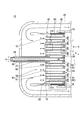
- FIG. 1 It is a figure showing a schematic structure of a gas turbine concerning an embodiment of the present invention. It is sectional drawing to which the part in which the fuel injector was arrange
- FIG. 1 A gas turbine 10 of the present embodiment will be described with reference to FIG.
- a generator 5 which is not a component of the gas turbine 10 is illustrated.
- the compressor 11, the turbine 12, the intermediate casing 13, and the combustor 15 are illustrated in cross section. Further, in FIG.
- A is compressed air (hereinafter referred to as “compressed air A”)
- Ao is outside air (hereinafter referred to as “outside air Ao")
- Ax is an axis of compressor 11 and turbine 12 (hereinafter referred to as “axis Ax” )
- CA is cooling air (hereinafter referred to as “cooling air CA”)
- F is a fuel gas (hereinafter referred to as “fuel gas F”
- G is a combustion gas (hereinafter referred to as “combusted gas G”). It shows.
- the gas turbine 10 includes a compressor 11, a turbine 12, an intermediate casing 13, a plurality of combustors 15, and a cooling device 17.
- the compressor 11 includes a compressor rotor 21, a compressor casing 23, and a plurality of compressor vane arrays 25.
- the compressor rotor 21 rotates about an axis Ax.
- the compressor rotor 21 has a compressor rotor shaft 27 and a plurality of compressor blade arrays 28.
- the compressor rotor shaft 27 extends in the direction of the axis Ax, and the axis coincides with the axis Ax.
- the plurality of compression blade arrays 28 are provided on the outer peripheral surface of the compressor rotor shaft 27.
- the plurality of compression blade arrays 28 are arranged at intervals in the direction of the axis Ax.
- the plurality of compression blade arrays 28 are constituted by a plurality of moving blades arranged in the circumferential direction of the compressor rotor shaft 27.
- external air Ao for example, air
- air taken in from the outside
- the compressed air A is generated by passing through the formed space.
- the generated compressed air A is supplied into the intermediate vehicle chamber 13.
- the compressor casing 23 is cylindrical and accommodates the compressor rotor 21.
- the plurality of compressor vane arrays 25 are fixed to the inside of the compressor casing 23.
- the compressor vane row 25 is disposed on the downstream side of each compression blade row 28.
- the plurality of compressor stator blade rows 25 are each configured by a plurality of stator blades arranged in the circumferential direction of the compressor casing 23.
- the turbine 12 has a turbine rotor 31, a turbine casing 33, and a plurality of turbine vane arrays 35.
- the turbine rotor 31 has a turbine rotor shaft 37 and a plurality of turbine moving blade cascades 38.
- the turbine rotor shaft 37 extends in the direction of the axis Ax and rotates around the axis Ax.
- One end of the turbine rotor shaft 37 is connected to the rotor of the generator 5.
- the plurality of turbine moving blade cascades 38 are provided on the outer peripheral surface of the turbine rotor shaft 37.
- the plurality of turbine blade arrays 38 are arranged at intervals in the direction of the axis Ax.
- the plurality of turbine moving blade cascades 38 are configured by a plurality of moving blades arranged in the circumferential direction of the turbine rotor shaft 37 respectively.
- the turbine rotor 31 configured as described above is connected to the compressor rotor 21 described above in the direction of the axis Ax. Thereby, the turbine rotor 31 and the compressor rotor 21 rotate integrally.
- the turbine rotor 31 and the compressor rotor 21 constitute a gas turbine rotor 42.
- the turbine casing 33 is cylindrical and accommodates the turbine rotor 31.
- the plurality of turbine vane arrays 35 are provided inside the turbine casing 33.
- the turbine stator blade row 35 is disposed upstream of each turbine blade row 38.
- the plurality of turbine vane arrays 35 are configured by a plurality of vanes arranged in the circumferential direction of the turbine casing 33 respectively.
- generated by the combustor 15 mentioned later is supplied to the turbine 12 set as the said structure. Then, the combustion gas G passes through the space formed between the turbine stator blade row 35 and the turbine moving blade row 38, whereby the turbine rotor shaft 37 is rotationally driven. Thus, rotational power is applied to the generator 5 connected to the gas turbine rotor 42, and power generation is performed.
- the intermediate casing 13 is provided between the compressor casing 23 and the turbine casing 33.
- the intermediate casing 13 is a cylindrical member extending in the direction of the axis Ax. The end on the upstream side in the axis line Ax direction of the intermediate casing 13 is connected to the compressor casing 23. The end on the downstream side in the axis line Ax direction of the intermediate casing 13 is connected to the turbine casing 33.
- I, J, and M indicate regions (hereinafter, referred to as “region I”, “region J”, and “region M,” respectively), and L indicates a central axis of the fuel injector 50 (hereinafter referred to as “central axis L X direction indicates the extending direction of the central axis L, respectively.
- L indicates a central axis of the fuel injector 50 (hereinafter referred to as “central axis L X direction indicates the extending direction of the central axis L, respectively.
- the arrows attached in the vicinity of the downstream side plate 59 schematically show how the mixed gas of the compressed air A and the fuel gas F is ejected.
- FIG. 3 the same components as those of the structure shown in FIG. In FIG. 4, the same components as those shown in FIGS. 2 and 3 are denoted by the same reference numerals.
- FIG. 5 the same components as those shown in FIGS. 2 and 4 are denoted by the same reference numerals.
- FIG. 6 the same components as those shown in FIGS. 2 to 4 are denoted by the same reference numerals.
- the combustor 15 has an outer cylinder 49, a fuel injector 50, a combustion cylinder 52, and a spring member 55.
- the outer cylinder 49 is a cylindrical member whose both ends are open ends.
- a plurality of outer cylinders 49 are provided in the intermediate vehicle chamber 13 in a state where a part of the outer cylinder 49 is disposed in the intermediate vehicle chamber 13.
- the plurality of outer cylinders 49 are arranged around the axis line Ax in a state of being separated from each other.
- the outer cylinder 49 burns a gas (mixed gas) in which the compressed air A injected from the fuel injector 50 and the fuel gas F are mixed, thereby generating a high temperature / high pressure combustion gas G.
- the outlet side of the outer cylinder 49 is connected to the turbine casing 33.
- the outer cylinder 49 supplies the generated combustion gas G into the turbine casing 33.
- the fuel injector 50 is accommodated in the outer cylinder 49, and the upstream plate 58, the downstream plate 59, the cylindrical member 62, the fuel tube 64, the premixing tube 65, and the cooling air introducing tube 68. And.
- the upstream plate 58 has a plate body 71, a fuel tube insertion hole 73, and a premix tube insertion hole 75.
- the plate main body 71 is a plate-like member, and is disposed inside the cylindrical member 62 located on the upstream side.
- the outer peripheral surface of the plate main body 71 is connected to the inner peripheral surface of the cylindrical member 62.
- a circular metal plate can be used as the plate main body 71.
- the fuel tube insertion hole 73 is formed to penetrate the central portion of the plate main body 71 in the X direction.
- the fuel tube insertion hole 73 is a hole into which the tip of the fuel tube 64 is inserted.
- a plurality of premixing tube insertion holes 75 are provided in the plate body 71 located outside the fuel tube insertion hole 73.
- the premix tube insertion hole 75 penetrates the plate body 71 in the X direction.
- the premix tube insertion hole 75 is a hole into which the upstream end of the premix tube 65 is inserted. Compressed air A is introduced into the premix tube insertion hole 75 with the upstream end of the premix tube 65 inserted.
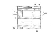
- the downstream side plate 59 is disposed inside the cylindrical member 62 located on the downstream side of the upstream side plate 58, and defines the plenum 60 together with the upstream side plate 58 and the cylindrical member 62.
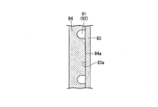
- the downstream side plate 59 has a first plate portion 83, a second plate portion 84, a premixing tube insertion hole 85, an air introducing portion 86, a distributing portion 88, and a cooling channel 91.
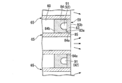
- the first plate portion 83 is a plate-like member, and is disposed inside the cylindrical member 62 located on the downstream side of the upstream plate 58.
- the outer peripheral surface of the first plate portion 83 is connected to the inner peripheral surface of the cylindrical member 62.
- the first plate portion 83 has a first surface 83 a facing the upstream plate 58 in the X direction, and a surface 83 b disposed on the opposite side of the first surface 83 a.
- the surface 83 b of the first plate portion 83 is a surface on which the adhesion flame may be generated. For this reason, the surface 83b side of the first plate portion 83 tends to have a higher temperature than the first surface 83a side.
- a circular metal plate can be used as the first plate portion 83.
- the second plate portion 84 is a plate-like member, and is provided inside the cylindrical member 62 located on the upstream side of the first plate portion 83.
- the second plate portion 84 is arranged to be in contact with the first surface 83a.
- the second plate portion 84 is joined to the first surface 83a.
- the second plate portion 84 has a second surface 84 a joined to the first surface 83 a and a surface 84 b disposed on the opposite side of the second surface 84 a.
- the surface 84b defines the end of the plenum 60 located downstream in the X direction.
- the first plate portion 83 is disposed downstream of the second plate portion 84. Therefore, the temperature of the second plate portion 84 is lower than the temperature of the first plate portion 83.
- a plurality of premix tube insertion holes 85 are formed to penetrate the first and second plate portions 83 and 84 in the X direction.
- the plurality of premix tube insertion holes 85 are disposed at positions opposed to one premix tube insertion hole 75 disposed in the X direction.
- the premix tube insertion hole 85 is a hole into which the downstream end of the premix tube 65 is inserted.
- the air introduction portion 86 is a recess formed in the second plate portion 84 from the second surface 84 a side, and is connected to the downstream end of the cooling air introduction pipe 68.
- the air introduction unit 86 is connected to the distribution unit 88 provided in each sector 90.
- the air introduction portion 86 configured in this way, it is not necessary to provide a plenum for cooling air, and only the plenum 60 for fuel gas may be provided, so the structure of the fuel injector 50 is simplified. It can be done.
- the distributing portion 88 is a recess formed in the second plate portion 84 from the second surface 84 a side, and is in communication with the plurality of cooling channels 91.
- the distribution unit 88 has a function of distributing the cooling air CA introduced from the cooling air introduction pipe 68 to the plurality of cooling channels 91.
- a plurality of cooling channels 91 are formed in the second plate portion 84.
- As the cooling channel 91 for example, it is possible to use a groove 92 recessed from the second surface 84a to the upstream plate 58 side.
- the cooling air CA distributed by the distributing unit 88 flows through the cooling flow passage 91.
- the cooling air CA flowing through the cooling flow passage 91 is air for cooling the first and second plate portions 83 and 84.
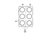
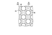
- the cooling channels 91 are arranged to extend in a direction along the surface (first surface 83 a) of the downstream side plate 59 so as to avoid the premixing tube 65.
- “extending avoiding the premixing tube 65” means, as shown in FIG. 7 and FIG. 8, a case where the cooling flow passage 91 is disposed linearly to avoid the premixing tube 65 or Including the case where the cooling channel 91 is disposed in the zigzag to avoid the premix tube 65, and the like.
- FIGS. 7 and 8 the same components as those of the structure shown in FIG.
- the downstream plate 59 can be directly cooled by the cooling air CA.
- the downstream plate 59 can be efficiently cooled using a smaller amount of the cooling air CA, as compared to the case where the cooling air CA is sprayed from the outside of the downstream plate 59.
- the cooling flow passage 91 in the second plate portion 84 disposed upstream of the first plate portion 83, not in the first plate portion 83 where the adhering flame may be formed. It is possible to reduce the thickness of the first plate portion 83 which is likely to be hotter than the second plate portion 84. Thereby, the thin first plate portion 83 can be efficiently cooled using the cooling air CA flowing in the cooling flow passage 91.
- the cooling flow passage 91 By using a groove 92 recessed from the second surface 84 a toward the upstream plate 58 as the cooling flow passage 91, a portion of the cooling air CA flowing through the cooling flow passage 91 can be made of the first plate portion 83. Since it is possible to make direct contact with the first surface 83 a, the first plate portion 83 can be efficiently cooled compared to the case where the cooling flow passage 91 is provided in the second plate portion 84. Can.
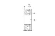
- the cylindrical member 62 is a cylindrical metal member whose upstream and downstream sides in the X direction are open ends.
- the tubular member 62 is a member for accommodating the first and second plate portions 83 and 84 and for partitioning the plenum 60 together with the first and second plate portions 83 and 84.
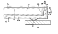
- the cylindrical member 62 is connected to the cooling flow passage 91 formed in the downstream side plate 59, and the space in the outer cylinder formed with the cooling air CA drawn from the cooling flow passage 91 on the upstream side of the upstream side plate 58 An exhaust path 62A for exhausting air.
- the cooling air CA exhausted from the exhaust path 62A can be reused as the air introduced into the premixing tube 65.
- the fuel tube 64 extends in the X direction, and is joined to the upstream plate 58 in a state in which the tip end portion is inserted into the fuel tube insertion hole 73.
- the fuel tube 64 supplies fuel gas to the plenum 60.
- the premixing tube 65 is a tubular tube whose upstream and downstream sides are open ends.
- the premixing tube 65 is provided to penetrate the upstream plate 58, the downstream plate 59, and the plenum 60 in the X direction.
- the upstream end of the premixing tube 65 is disposed in the premixing tube insertion hole 75 and is joined to a plate main body 71 that defines the premixing tube insertion hole 75.
- the downstream end of the premixing tube 65 is disposed in the premixing tube insertion hole 85, and is joined to first and second plate portions 83 and 84 that define the premixing tube insertion hole 85.
- the premixing tube 65 has fuel holes 65A for guiding the fuel gas F introduced into the plenum 60 into the premixing tube 65.
- the fuel gas F introduced into the premixing tube 65 from the fuel holes 65A is mixed with the compressed air A in the premixing tube 65.
- the cooling air introduction pipe 68 is disposed in the fuel tube 64 and in the plenum 60 with the downstream end connected to the second plate portion 84.
- the cooling air inlet pipe 68 introduces the cooling air CA into the air inlet 86.
- the downstream plate 59 can be directly cooled by the cooling air CA. Become.
- the downstream plate 59 can be efficiently cooled using a smaller amount of the cooling air CA, as compared to the case where the cooling air CA is sprayed from the outside of the downstream plate 59.
- the downstream side plate 59 with the air introducing portion 86 into which the cooling air CA from the cooling air introducing pipe 68 is introduced, it is not necessary to provide a plenum for the cooling air, and only the fuel gas plenum 60 can be provided.
- the structure of the fuel injector 50 can be simplified because it may be provided.
- FIGS. 9 to 12 a method of forming the downstream side plate 59 and a method of joining the premix tube 65 to the downstream side plate 59 will be described.
- FIGS. 9 to 12 the same components as those shown in FIG. 4 are designated by the same reference numerals.
- the cooling flow path 91 is formed by processing the groove 92 from the second surface 84 a side of the second plate portion 84.
- the second plate portion 84 and the first plate portion 84 are in contact with the second surface 84a of the second plate portion 84 and the first surface 83a of the first plate portion 83.
- the plate portion 83 of the As a joining method for example, brazing can be used.
- a premix tube insertion hole 85 penetrating the first and second plate portions 83 and 84 is formed.
- the air introduction portion 86 and the distribution portion 88 may be formed together with the premix tube insertion hole 85 in the process shown in FIG.
- the premix tube insertion hole 85 is fixed to the downstream plate 59 by welding in a state where the downstream end of the premix tube 65 is inserted into the premix tube insertion hole 85.
- the combustion cylinder 52 is a cylindrical member, and accommodates the downstream side of the fuel injector 50 with a gap interposed.
- the spring member 55 is disposed between the outer peripheral surface of the fuel injector 50 and the inner peripheral surface of the combustion cylinder 52.
- the position of the fuel injector 50 in the outer cylinder 49 is regulated by the combustion cylinder 52 and the spring member 55.
- the cooling device 17 is a device for extracting a part of the compressed air A supplied to the combustor 15 and supplying it to the fuel injector 50 after being compressed again.
- the cooling device 17 has a bleed portion 101, a cooler 103, a forced air-cooling compressor 104, an antisurge valve 105, and a cooling air introduction line 106.
- the bleed unit 101 is provided in the intermediate vehicle room 13.
- the bleed unit 101 bleeds the compressed air A introduced into the intermediate vehicle chamber 13.
- the extracted compressed air A is supplied to the cooler 103.
- the cooler 103 cools the extracted compressed air A.
- the compressed air A cooled by the cooler 103 is supplied to a forced air-cooling compressor 104.
- the compressed air A can be cooled.
- the cooling air CA having a temperature lower than that of the extracted compressed air A can be supplied to the combustor 15.
- the forced air-cooling compressor 104 further generates the cooling air CA by further compressing the compressed air A cooled by the cooler 103.
- the cooling air CA generated by the forced air-cooling compressor 104 is led to the cooling air introduction line 106.
- the anti-surge valve 105 prevents the surge of the forced air-cooling compressor 104.
- the cooling air inlet line 106 is connected to the cooling air inlet pipe 68 shown in FIG.
- the cooling air introduction line 106 causes the cooling air introduction pipe 68 to introduce the cooling air CA.
- the cooling air CA may be supplied to another cooling target of the gas turbine 10, for example, a stator blade.
- the cooling device 17 described above includes the forced air-cooling compressor 104, the compressed air A extracted from the extraction unit 101 can be further compressed. As a result, the cooling air CA, which is at a higher pressure than the extracted compressed air A, can be supplied to the combustor 15. Moreover, by having the forced air-cooling compressor 104, the cross-sectional area of the cooling flow path 91 can be made small.
- FIG. 2 as an example, the case where one system of cooling device 17 is provided for one gas turbine 10 has been described as an example, but a plurality of systems of cooling are provided for one gas turbine 10.
- a device 17 may be provided.
- the downstream plate 59 can be efficiently cooled and the gas turbine 10 can be stably operated by including the combustor 15.
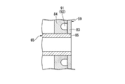
- FIG. 13 a part of the fuel injector 110 is illustrated in an enlarged state.
- the same components as those of the structure shown in FIG. 13 the same components as those of the structure shown in FIG.
- the fuel injector 110 makes the thickness of the second plate portion 84 thicker than that of the first plate portion 83, and provides the cooling flow path 91 (groove 92) in the second plate portion 84, It is comprised similarly to the fuel injector 50 of this embodiment.
- the cooling channel 91 (groove 92) may be provided in the second plate portion 84.
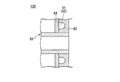
- FIG. 14 a part of the fuel injector 120 is illustrated in an enlarged state.
- the same components as in the structure shown in FIG. 14 the same components as in the structure shown in FIG. 14
- the fuel injector 120 is configured in the same manner as the fuel injector 50 of the present embodiment, except for having a through hole 111 penetrating a portion facing the groove 92 in the first plate portion 83.
- the through hole 111 configured as described above, it becomes possible to cool the first plate portion 83 from the inside of the first plate portion 83 by the cooling air CA flowing through the through hole 111 and it is possible to penetrate
- the cooling air CA discharged from the holes 111 can cool the surface 83 b of the first plate portion 83. Thereby, the 1st plate part 83 can be cooled very efficiently.
- the compressed air A compressed by the compressor 11 is supplied as the cooling air CA to the fuel injectors 50, 110, and 120 after passing through the cooling device 17 as an example.
- the compressed air A compressed by the compressor 11 may be supplied to the fuel injectors 50, 110, and 120 as the cooling air CA without passing through the cooling device 17.
- the present invention is applicable to fuel injectors, combustors, and gas turbines.
Abstract
The present invention is provided with a downstream plate (59) that is provided on the downstream side of an upstream plate (58) and includes: an air introduction portion (86) to which cooling air from a cooling air introduction pipe (68) is introduced; and a cooling flow path (91) which extends from the air introduction portion (86) in a direction along the surface of the downstream plate (59) so as to avoid a premixing tube (65) and through which the cooling air flows.
Description
本発明は、燃料噴射器、燃焼器、及びガスタービンに関する。
本願は、2017年11月30日に、日本に出願された特願2017-231143号に基づき優先権を主張し、その内容をここに援用する。 The present invention relates to a fuel injector, a combustor, and a gas turbine.
Priority is claimed on Japanese Patent Application No. 2017-231143, filed Nov. 30, 2017, the content of which is incorporated herein by reference.
本願は、2017年11月30日に、日本に出願された特願2017-231143号に基づき優先権を主張し、その内容をここに援用する。 The present invention relates to a fuel injector, a combustor, and a gas turbine.
Priority is claimed on Japanese Patent Application No. 2017-231143, filed Nov. 30, 2017, the content of which is incorporated herein by reference.
ガスタービンの燃焼器は、燃料噴射器を有する。燃料噴射器は、圧縮空気と燃料ガスとを予め均一に混合させる。そして、燃焼器は、高温の燃焼ガスを生成する。
The combustor of the gas turbine has a fuel injector. The fuel injector mixes the compressed air and the fuel gas uniformly in advance. The combustor then produces a high temperature combustion gas.
ガスタービンの燃焼器としては、燃焼が安定し、かつ環境負荷物質であるCO・NOx排出量が少ないものが好ましい。
このような燃焼器として、多孔噴流バーナ(「クーラスタバーナ」ともいう)を搭載したものが知られている(例えば、特許文献1参照)。 As a combustor of a gas turbine, one having stable combustion and low emissions of CO and NOx, which are environmentally harmful substances, is preferable.
As such a combustor, one equipped with a porous jet burner (also referred to as a "coulaster burner") is known (see, for example, Patent Document 1).
特許文献1には、上流側に配置され、複数の空気孔が形成された上流側プレートと、上流側プレートの下流側に配置され、複数の空気孔が形成された下流側プレートと、燃料送給チューブと、を備えた燃料噴射器が開示されている。
In Patent Document 1, an upstream plate disposed upstream and having a plurality of air holes formed therein, a downstream plate disposed downstream of the upstream plate and having a plurality of air holes formed therein, and a fuel feed A fuel injector comprising a feed tube is disclosed.
ところで、特許文献1に記載の燃料噴射器では、下流側プレートにおいて、付着火炎が発生する可能性がある。このため、下流側プレートを冷却する必要がある。そして、下流側プレートの冷却を効率良く行うことが望まれている。
By the way, in the fuel injector described in Patent Document 1, there is a possibility that an attached flame may be generated on the downstream side plate. For this reason, it is necessary to cool the downstream plate. And, it is desirable to efficiently cool the downstream side plate.
そこで、本発明は、下流側プレートを効率良く冷却することの可能な燃料噴射器、燃焼器、及びガスタービンを提供することを目的とする。
Therefore, the present invention aims to provide a fuel injector, a combustor, and a gas turbine capable of efficiently cooling the downstream side plate.
上記課題を解決するため、本発明の一態様に係る燃料噴射器は、上流側プレートと、前記上流側プレートの下流側に設けられ、該上流側プレートに対して対向配置された下流側プレートと、上流側及び下流側が開放端とされた筒状をなしており、上流側の開放端に配置された前記上流側プレート、及び下流側の開放端に配置された前記下流側プレートとともに内部にプレナムを区画する筒状部材と、前記プレナムに燃料ガスを導入する燃料チューブと、前記上流側プレート、前記下流側プレート、及び前記プレナムを貫くように延びる管状をなし、上流側及び下流側が開放端とされており、前記プレナム内に供給された前記燃料ガスを内側に導入する燃料孔を有し、前記燃料ガスと上流側の開放端から導入された空気とを混合する予混合チューブと、前記下流側プレートに冷却空気を導入する冷却空気導入管と、を備え、前記下流側プレートは、前記冷却空気導入管からの前記冷却空気が導入される空気導入部と、該空気導入部から前記下流側プレートの面に沿う方向に向かって、前記予混合チューブを避けるように延びる冷却流路と、を有する。
In order to solve the above problems, a fuel injector according to an aspect of the present invention includes an upstream plate, and a downstream plate provided on the downstream side of the upstream plate and disposed opposite to the upstream plate. An upstream side and a downstream side of the tubular form having an open end, and the upstream side plate disposed at the upstream open end and the downstream side plate disposed at the downstream open end are internally plenums. , A tubular member extending through the upstream plate, the downstream plate, and the plenum, the upstream side and the downstream side being open ends; And a pre-mixing channel having a fuel hole for introducing the fuel gas supplied into the plenum to the inside, and mixing the fuel gas with air introduced from the upstream open end. A cooling air introducing pipe for introducing cooling air to the downstream side plate, the downstream side plate including an air introducing portion into which the cooling air from the cooling air introducing pipe is introduced, and the air And a cooling channel extending away from the premixing tube in a direction along the surface of the downstream side plate from the introducing part.
本発明によれば、高温となる下流側プレートに冷却空気が流れる冷却流路を設けることで、冷却空気で直接下流側プレートを冷却することが可能となる。これにより、下流側プレートの外側から冷却空気を吹き付ける場合と比較して、少ない量の冷却空気を用いて効率良く下流側プレートを冷却させることができる。
According to the present invention, it is possible to directly cool the downstream side plate with the cooling air by providing the cooling flow passage through which the cooling air flows in the downstream side plate which becomes high temperature. Thus, the downstream plate can be efficiently cooled using a smaller amount of cooling air as compared to the case where the cooling air is blown from the outside of the downstream plate.
また、下流側プレートに、冷却空気導入管からの冷却空気が導入される空気導入部を設けることで、冷却空気用のプレナムを設ける必要が無くなり、燃料ガス用のプレナムのみを設ければよいため、燃料噴射器の構造を簡略化させることができる。
Further, by providing the downstream side plate with the air introduction portion into which the cooling air from the cooling air introduction pipe is introduced, it is not necessary to provide the plenum for the cooling air, and it is sufficient to provide only the fuel gas plenum. The structure of the fuel injector can be simplified.
また、本発明の一態様に係る燃料噴射器において、前記下流側プレートは、前記上流側プレートと対向する第1の面を有する第1のプレート部と、前記第1のプレート部の上流側に配置され、前記第1の面に対して接合される第2の面、及び前記冷却流路を有する第2のプレート部と、を備えてもよい。
Further, in the fuel injector according to one aspect of the present invention, the downstream plate includes a first plate portion having a first surface facing the upstream plate, and an upstream side of the first plate portion. The second surface may be disposed and joined to the first surface, and a second plate portion having the cooling channel.
このように、付着火炎が形成される可能性のある第1のプレート部ではなく、第1のプレート部の上流側に配置された第2のプレート部に冷却流路を形成することで、第2のプレート部よりも高温になりやすい第1のプレート部の厚さを薄くすることが可能となる。
これにより、冷却流路内を流れる冷却空気を用いて、厚さの薄い第1のプレート部を効率良く冷却することができる。 Thus, the cooling flow path is formed by forming the cooling flow path not in the first plate portion where the adhering flame may be formed, but in the second plate portion disposed upstream of the first plate portion. It becomes possible to reduce the thickness of the first plate portion which tends to be hotter than the plate portion 2.
Thus, the thin first plate portion can be efficiently cooled using the cooling air flowing in the cooling flow path.
また、本発明の一態様に係る燃料噴射器において、前記冷却流路は、前記第2の面から前記上流側プレート側に凹んだ溝であってもよい。
Further, in the fuel injector according to one aspect of the present invention, the cooling flow passage may be a groove recessed from the second surface to the upstream plate side.
このような構成とすることで、冷却流路を流れる冷却空気の一部を、第1のプレート部の第1の面に直接接触させることが可能となるので、第2のプレート部に冷却流路を内設させた場合と比較して、第1のプレート部を効率良く冷却することができる。
With such a configuration, a part of the cooling air flowing through the cooling flow passage can be brought into direct contact with the first surface of the first plate portion, so that the cooling flow to the second plate portion The first plate portion can be cooled more efficiently than in the case where the passage is internally provided.
また、本発明の一態様に係る燃料噴射器において、前記第1のプレート部は、前記溝と対向する部分を貫通する貫通孔を有してもよい。
Further, in the fuel injector according to one aspect of the present invention, the first plate portion may have a through hole penetrating a portion facing the groove.
このような構成とされた貫通孔を有することで、貫通孔を流れる冷却空気により第1のプレート部の内部から第1のプレート部を冷却させることが可能になるとともに、貫通孔から吐出された冷却空気により、第1の面の反対側に配置された第1のプレートの面を冷却させることが可能となるので、第1のプレート部を非常に効率良く冷却させることができる。
By having such a through hole, it becomes possible to cool the first plate portion from the inside of the first plate portion by the cooling air flowing through the through hole, and it is discharged from the through hole The cooling air makes it possible to cool the surface of the first plate arranged opposite to the first surface, so that it is possible to cool the first plate part very efficiently.
また、本発明の一態様に係る燃料噴射器において、前記筒状部材は、前記下流側プレートを通過した前記冷却空気を前記上流側プレートよりも上流側に排気するための排気経路を有してもよい。
Further, in the fuel injector according to one aspect of the present invention, the cylindrical member has an exhaust path for discharging the cooling air having passed through the downstream plate to the upstream side of the upstream plate. It is also good.
このような構成とされた排気経路を有することで、排気経路から排気された冷却空気を予混合チューブ内に導入される空気として再利用することができる。
By having the exhaust path configured in this way, the cooling air exhausted from the exhaust path can be reused as the air introduced into the premix tube.
上記課題を解決するため、本発明の一態様に係る燃焼器は、上記燃料噴射器と、前記燃料噴射器を収容するとともに、前記燃料噴射器から噴射された燃料ガスと空気とが混合されたガスを燃焼させて、燃焼ガスを生成する燃焼筒と、を有する。
In order to solve the above-mentioned subject, a burner concerning one mode of the present invention stores the above-mentioned fuel injector and the above-mentioned fuel injector, and fuel gas and air which were injected from the above-mentioned fuel injector were mixed. And b) burning the gas to produce a combustion gas.
本発明によれば、上記燃料噴射器を有することで、下流側プレートを効率良く冷却することができるとともに、安定して燃焼器を稼働させることができる。
According to the present invention, by having the fuel injector, the downstream plate can be efficiently cooled, and the combustor can be operated stably.
上記課題を解決するため、本発明の一態様に係るガスタービンは、上記燃焼器と、圧縮空気を生成するとともに、前記燃料噴射器に前記空気として前記圧縮空気を供給する圧縮機と、前記圧縮機により生成された前記圧縮空気を抽気する抽気部と、前記抽気部により抽気された圧縮空気をさらに圧縮して、冷却空気を生成する強制空冷圧縮機と、前記強制空冷圧縮機が生成した前記冷却空気を前記燃焼器に導入する冷却空気導入ラインと、を備える。
In order to solve the above-mentioned subject, a gas turbine concerning one mode of the present invention generates the above-mentioned burner, compressed air as well as a compressor which supplies the above-mentioned compressed air as the above-mentioned air to the above-mentioned fuel injector, and the above-mentioned compression An air extraction unit for extracting the compressed air generated by the machine, a forced air cooling compressor for further compressing the compressed air extracted by the extraction unit to generate cooling air, and the air generated by the forced air cooling compressor And a cooling air inlet line for introducing cooling air into the combustor.
本発明によれば、上記燃焼器を有することで、下流側プレートを効率良く冷却することができるとともに、安定してガスタービンを稼働させることができる。
また、強制空冷圧縮機を有することで、抽気部により抽気された圧縮空気をさらに圧縮することが可能となる。これにより、抽気した圧縮空気よりも高い圧力とされた冷却空気を燃焼器に供給することができる。
さらに、強制空冷圧縮機を有することで、冷却流路の断面積を小さくすることができる。 According to the present invention, the downstream plate can be efficiently cooled and the gas turbine can be stably operated by including the combustor.
Further, by having the forced air-cooling compressor, it is possible to further compress the compressed air extracted by the extraction unit. As a result, it is possible to supply the combustion air with cooling air that is at a higher pressure than the extracted compressed air.
Furthermore, by having a forced air-cooling compressor, the cross-sectional area of the cooling channel can be reduced.
また、本発明の一態様に係るガスタービンにおいて、前記抽気部により抽気された圧縮空気を冷却するクーラを備えてもよい。
Moreover, the gas turbine which concerns on 1 aspect of this invention WHEREIN: You may provide the cooler which cools the compressed air extracted by the said extraction part.
このような構成とされたクーラを有することで、圧縮空気を冷却することが可能となる。これにより、抽気した圧縮空気よりも温度の低い冷却空気を燃焼器に供給することができる。
By having the cooler thus configured, it is possible to cool the compressed air. Thus, cooling air having a temperature lower than that of the extracted compressed air can be supplied to the combustor.
本発明によれば、下流側プレートを効率良く冷却することができる。
According to the present invention, the downstream plate can be cooled efficiently.
以下、図面を参照して本発明を適用した実施形態について詳細に説明する。
Hereinafter, embodiments to which the present invention is applied will be described in detail with reference to the drawings.
(実施形態)
図1を参照して、本実施形態のガスタービン10について説明する。図1では、ガスタービン10の構成要素ではない発電機5を図示する。図1では、説明の便宜上、圧縮機11、タービン12、中間車室13、及び燃焼器15を断面で図示する。
また、図1において、Aは圧縮空気(以下、「圧縮空気A」という)、Aoは外気(以下、「外気Ao」という)、Axは圧縮機11及びタービン12の軸線(以下、「軸線Ax」という)、CAは冷却空気(以下、「冷却空気CA」という)、Fは燃料ガス(以下、「燃料ガスF」という)、Gは燃焼ガス(以下、「燃焼ガスG」という)をそれぞれ示している。 (Embodiment)
Agas turbine 10 of the present embodiment will be described with reference to FIG. In FIG. 1, a generator 5 which is not a component of the gas turbine 10 is illustrated. In FIG. 1, for convenience of explanation, the compressor 11, the turbine 12, the intermediate casing 13, and the combustor 15 are illustrated in cross section.
Further, in FIG. 1, A is compressed air (hereinafter referred to as "compressed air A"), Ao is outside air (hereinafter referred to as "outside air Ao"), Ax is an axis ofcompressor 11 and turbine 12 (hereinafter referred to as "axis Ax" ), CA is cooling air (hereinafter referred to as “cooling air CA”), F is a fuel gas (hereinafter referred to as “fuel gas F”, and G is a combustion gas (hereinafter referred to as “combusted gas G”). It shows.
図1を参照して、本実施形態のガスタービン10について説明する。図1では、ガスタービン10の構成要素ではない発電機5を図示する。図1では、説明の便宜上、圧縮機11、タービン12、中間車室13、及び燃焼器15を断面で図示する。
また、図1において、Aは圧縮空気(以下、「圧縮空気A」という)、Aoは外気(以下、「外気Ao」という)、Axは圧縮機11及びタービン12の軸線(以下、「軸線Ax」という)、CAは冷却空気(以下、「冷却空気CA」という)、Fは燃料ガス(以下、「燃料ガスF」という)、Gは燃焼ガス(以下、「燃焼ガスG」という)をそれぞれ示している。 (Embodiment)
A
Further, in FIG. 1, A is compressed air (hereinafter referred to as "compressed air A"), Ao is outside air (hereinafter referred to as "outside air Ao"), Ax is an axis of
ガスタービン10は、圧縮機11と、タービン12と、中間車室13と、複数の燃焼器15と、冷却装置17と、を備える。
The gas turbine 10 includes a compressor 11, a turbine 12, an intermediate casing 13, a plurality of combustors 15, and a cooling device 17.
圧縮機11は、圧縮機ロータ21と、圧縮機車室23と、複数の圧縮機静翼列25と、を有している。
The compressor 11 includes a compressor rotor 21, a compressor casing 23, and a plurality of compressor vane arrays 25.
圧縮機ロータ21は、軸線Ax周りに回転する。圧縮機ロータ21は、圧縮機ロータ軸27と、複数の圧縮機動翼列28と、を有している。
The compressor rotor 21 rotates about an axis Ax. The compressor rotor 21 has a compressor rotor shaft 27 and a plurality of compressor blade arrays 28.
圧縮機ロータ軸27は、軸線Ax方向に延在しており、軸線が軸線Axと一致している。
複数の圧縮機動翼列28は、圧縮機ロータ軸27の外周面に設けられている。複数の圧縮機動翼列28は、軸線Ax方向に間隔を空けて配列されている。
複数の圧縮機動翼列28は、圧縮機ロータ軸27の周方向に配列された複数の動翼で構成される。 Thecompressor rotor shaft 27 extends in the direction of the axis Ax, and the axis coincides with the axis Ax.
The plurality ofcompression blade arrays 28 are provided on the outer peripheral surface of the compressor rotor shaft 27. The plurality of compression blade arrays 28 are arranged at intervals in the direction of the axis Ax.
The plurality ofcompression blade arrays 28 are constituted by a plurality of moving blades arranged in the circumferential direction of the compressor rotor shaft 27.
複数の圧縮機動翼列28は、圧縮機ロータ軸27の外周面に設けられている。複数の圧縮機動翼列28は、軸線Ax方向に間隔を空けて配列されている。
複数の圧縮機動翼列28は、圧縮機ロータ軸27の周方向に配列された複数の動翼で構成される。 The
The plurality of
The plurality of
上記構成とされた圧縮機11は、圧縮機ロータ21が回転した状態で、外部から取り込んだ外気Ao(例えば、空気)を複数の圧縮機静翼列25と圧縮機動翼列28との間に形成された空間を通過させることで、圧縮空気Aを生成する。生成された圧縮空気Aは、中間車室13内に供給される。
In the compressor 11 configured as described above, external air Ao (for example, air) taken in from the outside is placed between the plurality of compressor vane arrays 25 and the compressor blade array 28 while the compressor rotor 21 is rotated. The compressed air A is generated by passing through the formed space. The generated compressed air A is supplied into the intermediate vehicle chamber 13.
圧縮機車室23は、筒状とされており、圧縮機ロータ21を収容している。
複数の圧縮機静翼列25は、圧縮機車室23の内側に固定されている。圧縮機静翼列25は、各圧縮機動翼列28の各下流側にそれぞれ配置されている。複数の圧縮機静翼列25は、それぞれ圧縮機車室23の周方向に配列された複数の静翼で構成されている。 Thecompressor casing 23 is cylindrical and accommodates the compressor rotor 21.
The plurality ofcompressor vane arrays 25 are fixed to the inside of the compressor casing 23. The compressor vane row 25 is disposed on the downstream side of each compression blade row 28. The plurality of compressor stator blade rows 25 are each configured by a plurality of stator blades arranged in the circumferential direction of the compressor casing 23.
複数の圧縮機静翼列25は、圧縮機車室23の内側に固定されている。圧縮機静翼列25は、各圧縮機動翼列28の各下流側にそれぞれ配置されている。複数の圧縮機静翼列25は、それぞれ圧縮機車室23の周方向に配列された複数の静翼で構成されている。 The
The plurality of
タービン12は、タービンロータ31と、タービン車室33と、複数のタービン静翼列35と、を有している。
The turbine 12 has a turbine rotor 31, a turbine casing 33, and a plurality of turbine vane arrays 35.
タービンロータ31は、タービンロータ軸37と、複数のタービン動翼列38と、を有する。
タービンロータ軸37は、軸線Ax方向に延在しており、軸線Ax周りに回転する。タービンロータ軸37の一方の端部は、発電機5のロータと接続されている。 Theturbine rotor 31 has a turbine rotor shaft 37 and a plurality of turbine moving blade cascades 38.
Theturbine rotor shaft 37 extends in the direction of the axis Ax and rotates around the axis Ax. One end of the turbine rotor shaft 37 is connected to the rotor of the generator 5.
タービンロータ軸37は、軸線Ax方向に延在しており、軸線Ax周りに回転する。タービンロータ軸37の一方の端部は、発電機5のロータと接続されている。 The
The
複数のタービン動翼列38は、タービンロータ軸37の外周面に設けられている。複数のタービン動翼列38は、軸線Ax方向に間隔を空けた状態で配列されている。
複数のタービン動翼列38は、それぞれタービンロータ軸37の周方向に配列された複数の動翼で構成される。 The plurality of turbine moving blade cascades 38 are provided on the outer peripheral surface of theturbine rotor shaft 37. The plurality of turbine blade arrays 38 are arranged at intervals in the direction of the axis Ax.
The plurality of turbine moving blade cascades 38 are configured by a plurality of moving blades arranged in the circumferential direction of theturbine rotor shaft 37 respectively.
複数のタービン動翼列38は、それぞれタービンロータ軸37の周方向に配列された複数の動翼で構成される。 The plurality of turbine moving blade cascades 38 are provided on the outer peripheral surface of the
The plurality of turbine moving blade cascades 38 are configured by a plurality of moving blades arranged in the circumferential direction of the
上記構成とされたタービンロータ31は、軸線Ax方向において、先に説明した圧縮機ロータ21と連結されている。これにより、タービンロータ31及び圧縮機ロータ21は、一体に回転する。タービンロータ31及び圧縮機ロータ21は、ガスタービンロータ42を構成している。
The turbine rotor 31 configured as described above is connected to the compressor rotor 21 described above in the direction of the axis Ax. Thereby, the turbine rotor 31 and the compressor rotor 21 rotate integrally. The turbine rotor 31 and the compressor rotor 21 constitute a gas turbine rotor 42.
タービン車室33は、筒状とされており、タービンロータ31を収容している。
The turbine casing 33 is cylindrical and accommodates the turbine rotor 31.
複数のタービン静翼列35は、タービン車室33の内側に設けられている。タービン静翼列35は、各タービン動翼列38の上流側に配置されている。
複数のタービン静翼列35は、それぞれタービン車室33の周方向に配列された複数の静翼で構成されている。 The plurality ofturbine vane arrays 35 are provided inside the turbine casing 33. The turbine stator blade row 35 is disposed upstream of each turbine blade row 38.
The plurality ofturbine vane arrays 35 are configured by a plurality of vanes arranged in the circumferential direction of the turbine casing 33 respectively.
複数のタービン静翼列35は、それぞれタービン車室33の周方向に配列された複数の静翼で構成されている。 The plurality of
The plurality of
上記構成とされたタービン12には、後述する燃焼器15で生成された燃焼ガスGが供給される。そして、燃焼ガスGがタービン静翼列35とタービン動翼列38との間に形成された空間を通過することで、タービンロータ軸37が回転駆動される。
これにより、ガスタービンロータ42に連結された発電機5に回転動力が付与され、発電が行われる。 The combustion gas G produced | generated by thecombustor 15 mentioned later is supplied to the turbine 12 set as the said structure. Then, the combustion gas G passes through the space formed between the turbine stator blade row 35 and the turbine moving blade row 38, whereby the turbine rotor shaft 37 is rotationally driven.
Thus, rotational power is applied to thegenerator 5 connected to the gas turbine rotor 42, and power generation is performed.
これにより、ガスタービンロータ42に連結された発電機5に回転動力が付与され、発電が行われる。 The combustion gas G produced | generated by the
Thus, rotational power is applied to the
中間車室13は、圧縮機車室23とタービン車室33との間に設けられている。中間車室13は、軸線Ax方向に延在する筒状の部材である。中間車室13の軸線Ax方向上流側の端は、圧縮機車室23と接続されている。中間車室13の軸線Ax方向下流側の端は、タービン車室33と接続されている。
The intermediate casing 13 is provided between the compressor casing 23 and the turbine casing 33. The intermediate casing 13 is a cylindrical member extending in the direction of the axis Ax. The end on the upstream side in the axis line Ax direction of the intermediate casing 13 is connected to the compressor casing 23. The end on the downstream side in the axis line Ax direction of the intermediate casing 13 is connected to the turbine casing 33.
次に、図1~図6を参照して、燃料噴射器50について説明する。
図2では、図1に示す構造体と同一構成部分には同一符号を付す。また、図2において、I,J,Mは領域(以下、それぞれ「領域I」、「領域J」、「領域M」という)、Lは燃料噴射器50の中心軸(以下、「中心軸L」という)、X方向は中心軸Lの延在方向をそれぞれ示している。
さらに、図2において、下流側プレート59の近傍に付した矢印は、圧縮空気Aと燃料ガスFとが混合されたガスが噴き出す様子を模式的に示している。 Thefuel injector 50 will now be described with reference to FIGS.
In FIG. 2, the same components as those of the structure shown in FIG. Further, in FIG. 2, I, J, and M indicate regions (hereinafter, referred to as “region I”, “region J”, and “region M,” respectively), and L indicates a central axis of the fuel injector 50 (hereinafter referred to as “central axis L X direction indicates the extending direction of the central axis L, respectively.
Furthermore, in FIG. 2, the arrows attached in the vicinity of thedownstream side plate 59 schematically show how the mixed gas of the compressed air A and the fuel gas F is ejected.
図2では、図1に示す構造体と同一構成部分には同一符号を付す。また、図2において、I,J,Mは領域(以下、それぞれ「領域I」、「領域J」、「領域M」という)、Lは燃料噴射器50の中心軸(以下、「中心軸L」という)、X方向は中心軸Lの延在方向をそれぞれ示している。
さらに、図2において、下流側プレート59の近傍に付した矢印は、圧縮空気Aと燃料ガスFとが混合されたガスが噴き出す様子を模式的に示している。 The
In FIG. 2, the same components as those of the structure shown in FIG. Further, in FIG. 2, I, J, and M indicate regions (hereinafter, referred to as “region I”, “region J”, and “region M,” respectively), and L indicates a central axis of the fuel injector 50 (hereinafter referred to as “central axis L X direction indicates the extending direction of the central axis L, respectively.
Furthermore, in FIG. 2, the arrows attached in the vicinity of the
図3において、図2に示す構造体と同一構成部分には同一符号を付す。図4において、図2及び図3に示す構造体と同一構成部分には同一符号を付す。図5において、図2及び図4に示す構造体と同一構成部分には同一符号を付す。図6において、図2~図4に示す構造体と同一構成部分には同一符号を付す。
In FIG. 3, the same components as those of the structure shown in FIG. In FIG. 4, the same components as those shown in FIGS. 2 and 3 are denoted by the same reference numerals. In FIG. 5, the same components as those shown in FIGS. 2 and 4 are denoted by the same reference numerals. In FIG. 6, the same components as those shown in FIGS. 2 to 4 are denoted by the same reference numerals.
燃焼器15は、外筒49と、燃料噴射器50と、燃焼筒52と、ばね部材55と、を有する。
The combustor 15 has an outer cylinder 49, a fuel injector 50, a combustion cylinder 52, and a spring member 55.
外筒49は、両端が開放端とされた筒状の部材である。外筒49は、一部が中間車室13内に配置された状態で中間車室13に複数設けられている。複数の外筒49は、互いの間隔を空けた状態で軸線Ax周りに配列されている。
The outer cylinder 49 is a cylindrical member whose both ends are open ends. A plurality of outer cylinders 49 are provided in the intermediate vehicle chamber 13 in a state where a part of the outer cylinder 49 is disposed in the intermediate vehicle chamber 13. The plurality of outer cylinders 49 are arranged around the axis line Ax in a state of being separated from each other.
外筒49は、燃料噴射器50から噴射される圧縮空気Aと燃料ガスFとが混合されたガス(混合ガス)を燃焼させることで、高温・高圧の燃焼ガスGを生成する。
外筒49の出口側は、タービン車室33と接続されている。外筒49は、生成した燃焼ガスGをタービン車室33内へ供給する。 Theouter cylinder 49 burns a gas (mixed gas) in which the compressed air A injected from the fuel injector 50 and the fuel gas F are mixed, thereby generating a high temperature / high pressure combustion gas G.
The outlet side of theouter cylinder 49 is connected to the turbine casing 33. The outer cylinder 49 supplies the generated combustion gas G into the turbine casing 33.
外筒49の出口側は、タービン車室33と接続されている。外筒49は、生成した燃焼ガスGをタービン車室33内へ供給する。 The
The outlet side of the
燃料噴射器50は、外筒49内に収容されており、上流側プレート58と、下流側プレート59と、筒状部材62と、燃料チューブ64と、予混合チューブ65と、冷却空気導入管68と、を有する。
The fuel injector 50 is accommodated in the outer cylinder 49, and the upstream plate 58, the downstream plate 59, the cylindrical member 62, the fuel tube 64, the premixing tube 65, and the cooling air introducing tube 68. And.
上流側プレート58は、プレート本体71と、燃料チューブ挿入孔73と、予混合チューブ挿入孔75と、を有する。
The upstream plate 58 has a plate body 71, a fuel tube insertion hole 73, and a premix tube insertion hole 75.
プレート本体71は、板状の部材であり、上流側に位置する筒状部材62の内側に配置されている。プレート本体71の外周面は、筒状部材62の内周面と接続されている。プレート本体71としては、例えば、円形の金属製の板材を用いることができる。
The plate main body 71 is a plate-like member, and is disposed inside the cylindrical member 62 located on the upstream side. The outer peripheral surface of the plate main body 71 is connected to the inner peripheral surface of the cylindrical member 62. As the plate main body 71, for example, a circular metal plate can be used.
燃料チューブ挿入孔73は、プレート本体71の中央部をX方向に貫通するように形成されている。燃料チューブ挿入孔73は、燃料チューブ64の先端部が挿入される孔である。
The fuel tube insertion hole 73 is formed to penetrate the central portion of the plate main body 71 in the X direction. The fuel tube insertion hole 73 is a hole into which the tip of the fuel tube 64 is inserted.
予混合チューブ挿入孔75は、燃料チューブ挿入孔73の外側に位置するプレート本体71に複数設けられている。予混合チューブ挿入孔75は、プレート本体71をX方向に貫通している。予混合チューブ挿入孔75は、予混合チューブ65の上流側端部が挿入される孔である。予混合チューブ挿入孔75には、予混合チューブ65の上流側端部が挿入された状態で、圧縮空気Aが導入される。
A plurality of premixing tube insertion holes 75 are provided in the plate body 71 located outside the fuel tube insertion hole 73. The premix tube insertion hole 75 penetrates the plate body 71 in the X direction. The premix tube insertion hole 75 is a hole into which the upstream end of the premix tube 65 is inserted. Compressed air A is introduced into the premix tube insertion hole 75 with the upstream end of the premix tube 65 inserted.
下流側プレート59は、上流側プレート58の下流側に位置する筒状部材62の内側に配置されており、上流側プレート58及び筒状部材62とともにプレナム60を区画している。
下流側プレート59は、第1のプレート部83と、第2のプレート部84と、予混合チューブ挿入孔85と、空気導入部86と、分配部88と、冷却流路91と、を有する。 Thedownstream side plate 59 is disposed inside the cylindrical member 62 located on the downstream side of the upstream side plate 58, and defines the plenum 60 together with the upstream side plate 58 and the cylindrical member 62.
Thedownstream side plate 59 has a first plate portion 83, a second plate portion 84, a premixing tube insertion hole 85, an air introducing portion 86, a distributing portion 88, and a cooling channel 91.
下流側プレート59は、第1のプレート部83と、第2のプレート部84と、予混合チューブ挿入孔85と、空気導入部86と、分配部88と、冷却流路91と、を有する。 The
The
第1のプレート部83は、板状の部材であり、上流側プレート58の下流側に位置する筒状部材62の内側に配置されている。第1のプレート部83の外周面は、筒状部材62の内周面と接続されている。
The first plate portion 83 is a plate-like member, and is disposed inside the cylindrical member 62 located on the downstream side of the upstream plate 58. The outer peripheral surface of the first plate portion 83 is connected to the inner peripheral surface of the cylindrical member 62.
第1のプレート部83は、X方向において上流側プレート58と対向する第1の面83aと、第1の面83aの反対側に配置された面83bと、を有する。
第1のプレート部83の面83bは、付着火炎が発生する可能性のある面である。このため、第1のプレート部83の面83b側は、第1の面83a側よりも高温となりやすい。
第1のプレート部83としては、例えば、円形の金属製の板材を用いることができる。 Thefirst plate portion 83 has a first surface 83 a facing the upstream plate 58 in the X direction, and a surface 83 b disposed on the opposite side of the first surface 83 a.
Thesurface 83 b of the first plate portion 83 is a surface on which the adhesion flame may be generated. For this reason, the surface 83b side of the first plate portion 83 tends to have a higher temperature than the first surface 83a side.
As thefirst plate portion 83, for example, a circular metal plate can be used.
第1のプレート部83の面83bは、付着火炎が発生する可能性のある面である。このため、第1のプレート部83の面83b側は、第1の面83a側よりも高温となりやすい。
第1のプレート部83としては、例えば、円形の金属製の板材を用いることができる。 The
The
As the
第2のプレート部84は、板状の部材であり、第1のプレート部83の上流側に位置する筒状部材62の内側に設けられている。第2のプレート部84は、第1の面83aと接触するように配置されている。第2のプレート部84は、第1の面83aに対して接合されている。
The second plate portion 84 is a plate-like member, and is provided inside the cylindrical member 62 located on the upstream side of the first plate portion 83. The second plate portion 84 is arranged to be in contact with the first surface 83a. The second plate portion 84 is joined to the first surface 83a.
第2のプレート部84は、第1の面83aと接合される第2の面84aと、第2の面84aの反対側に配置された面84bと、を有する。面84bは、X方向下流側に位置するプレナム60の端を区画している。
上述したように、第2のプレート部84の下流側には第1のプレート部83が配置されている。このため、第2のプレート部84は、第1のプレート部83の温度よりも低い温度となる。 Thesecond plate portion 84 has a second surface 84 a joined to the first surface 83 a and a surface 84 b disposed on the opposite side of the second surface 84 a. The surface 84b defines the end of the plenum 60 located downstream in the X direction.
As described above, thefirst plate portion 83 is disposed downstream of the second plate portion 84. Therefore, the temperature of the second plate portion 84 is lower than the temperature of the first plate portion 83.
上述したように、第2のプレート部84の下流側には第1のプレート部83が配置されている。このため、第2のプレート部84は、第1のプレート部83の温度よりも低い温度となる。 The
As described above, the
予混合チューブ挿入孔85は、第1及び第2のプレート部83,84をX方向に貫通するように複数形成されている。複数の予混合チューブ挿入孔85は、それぞれX方向に配置された1つの予混合チューブ挿入孔75と対向する位置に配置されている。
予混合チューブ挿入孔85は、予混合チューブ65の下流側端部が挿入される孔である。 A plurality of premix tube insertion holes 85 are formed to penetrate the first and second plate portions 83 and 84 in the X direction. The plurality of premix tube insertion holes 85 are disposed at positions opposed to one premix tube insertion hole 75 disposed in the X direction.
The premixtube insertion hole 85 is a hole into which the downstream end of the premix tube 65 is inserted.
予混合チューブ挿入孔85は、予混合チューブ65の下流側端部が挿入される孔である。 A plurality of premix tube insertion holes 85 are formed to penetrate the first and
The premix
空気導入部86は、第2の面84a側から第2のプレート部84に形成された凹部であり、冷却空気導入管68の下流側端部と接続されている。空気導入部86は、各セクター90に設けられた分配部88と接続されている。
The air introduction portion 86 is a recess formed in the second plate portion 84 from the second surface 84 a side, and is connected to the downstream end of the cooling air introduction pipe 68. The air introduction unit 86 is connected to the distribution unit 88 provided in each sector 90.
このような構成とされた空気導入部86を有することで、冷却空気用のプレナムを設ける必要が無くなり、燃料ガス用のプレナム60のみを設ければよいため、燃料噴射器50の構造を簡略化させることができる。
By having the air introduction portion 86 configured in this way, it is not necessary to provide a plenum for cooling air, and only the plenum 60 for fuel gas may be provided, so the structure of the fuel injector 50 is simplified. It can be done.
分配部88は、第2の面84a側から第2のプレート部84に形成された凹部であり、複数の冷却流路91と連通している。
分配部88は、冷却空気導入管68から導入された冷却空気CAを複数の冷却流路91に分配する機能を有する。 The distributingportion 88 is a recess formed in the second plate portion 84 from the second surface 84 a side, and is in communication with the plurality of cooling channels 91.
Thedistribution unit 88 has a function of distributing the cooling air CA introduced from the cooling air introduction pipe 68 to the plurality of cooling channels 91.
分配部88は、冷却空気導入管68から導入された冷却空気CAを複数の冷却流路91に分配する機能を有する。 The distributing
The
冷却流路91は、第2のプレート部84に複数形成されている。冷却流路91としては、例えば、第2の面84aから上流側プレート58側に凹んだ溝92を用いることが可能である。
冷却流路91には、分配部88で分配された冷却空気CAが流れる。冷却流路91を流れる冷却空気CAは、第1及び第2のプレート部83,84を冷却するための空気である。冷却流路91は、下流側プレート59の面(第1の面83a)に沿う方向に向かって、予混合チューブ65を避けて延びるように配置されている。 A plurality ofcooling channels 91 are formed in the second plate portion 84. As the cooling channel 91, for example, it is possible to use a groove 92 recessed from the second surface 84a to the upstream plate 58 side.
The cooling air CA distributed by the distributingunit 88 flows through the cooling flow passage 91. The cooling air CA flowing through the cooling flow passage 91 is air for cooling the first and second plate portions 83 and 84. The cooling channels 91 are arranged to extend in a direction along the surface (first surface 83 a) of the downstream side plate 59 so as to avoid the premixing tube 65.
冷却流路91には、分配部88で分配された冷却空気CAが流れる。冷却流路91を流れる冷却空気CAは、第1及び第2のプレート部83,84を冷却するための空気である。冷却流路91は、下流側プレート59の面(第1の面83a)に沿う方向に向かって、予混合チューブ65を避けて延びるように配置されている。 A plurality of
The cooling air CA distributed by the distributing
なお、本実施形態において、「予混合チューブ65を避けて延びる」とは、図7及び図8に示すように、直線状に冷却流路91を配置させて予混合チューブ65を避ける場合や、ジクザグに冷却流路91を配置させて予混合チューブ65を避ける場合等を含む。
図7及び図8では、図5に示す構造体と同一構成部分には同一符号を付す。 In the present embodiment, “extending avoiding thepremixing tube 65” means, as shown in FIG. 7 and FIG. 8, a case where the cooling flow passage 91 is disposed linearly to avoid the premixing tube 65 or Including the case where the cooling channel 91 is disposed in the zigzag to avoid the premix tube 65, and the like.
In FIGS. 7 and 8, the same components as those of the structure shown in FIG.
図7及び図8では、図5に示す構造体と同一構成部分には同一符号を付す。 In the present embodiment, “extending avoiding the
In FIGS. 7 and 8, the same components as those of the structure shown in FIG.
このように、高温となる下流側プレート59に冷却空気CAが流れる冷却流路91を設けることで、冷却空気CAで直接下流側プレート59を冷却することが可能となる。これにより、下流側プレート59の外側から冷却空気CAを吹き付ける場合と比較して、少ない量の冷却空気CAを用いて効率良く下流側プレート59を冷却させることができる。
As described above, by providing the cooling flow passage 91 through which the cooling air CA flows in the downstream plate 59 having a high temperature, the downstream plate 59 can be directly cooled by the cooling air CA. Thus, the downstream plate 59 can be efficiently cooled using a smaller amount of the cooling air CA, as compared to the case where the cooling air CA is sprayed from the outside of the downstream plate 59.
また、付着火炎が形成される可能性のある第1のプレート部83ではなく、第1のプレート部83の上流側に配置された第2のプレート部84に冷却流路91を形成することで、第2のプレート部84よりも高温になりやすい第1のプレート部83の厚さを薄くすることが可能となる。
これにより、冷却流路91内を流れる冷却空気CAを用いて、厚さの薄い第1のプレート部83を効率良く冷却することができる。 Further, by forming thecooling flow passage 91 in the second plate portion 84 disposed upstream of the first plate portion 83, not in the first plate portion 83 where the adhering flame may be formed. It is possible to reduce the thickness of the first plate portion 83 which is likely to be hotter than the second plate portion 84.
Thereby, the thinfirst plate portion 83 can be efficiently cooled using the cooling air CA flowing in the cooling flow passage 91.
これにより、冷却流路91内を流れる冷却空気CAを用いて、厚さの薄い第1のプレート部83を効率良く冷却することができる。 Further, by forming the
Thereby, the thin
さらに、冷却流路91として、第2の面84aから上流側プレート58側に凹んだ溝92を用いることで、冷却流路91を流れる冷却空気CAの一部を、第1のプレート部83の第1の面83aに直接接触させることが可能となるので、第2のプレート部84に冷却流路91を内設させた場合と比較して、第1のプレート部83を効率良く冷却することができる。
Furthermore, by using a groove 92 recessed from the second surface 84 a toward the upstream plate 58 as the cooling flow passage 91, a portion of the cooling air CA flowing through the cooling flow passage 91 can be made of the first plate portion 83. Since it is possible to make direct contact with the first surface 83 a, the first plate portion 83 can be efficiently cooled compared to the case where the cooling flow passage 91 is provided in the second plate portion 84. Can.
筒状部材62は、X方向の上流側及び下流側が開放端とされた筒状の金属製の部材である。筒状部材62は、第1及び第2のプレート部83,84を収容するとともに、第1及び第2のプレート部83,84とともにプレナム60を区画するための部材である。
The cylindrical member 62 is a cylindrical metal member whose upstream and downstream sides in the X direction are open ends. The tubular member 62 is a member for accommodating the first and second plate portions 83 and 84 and for partitioning the plenum 60 together with the first and second plate portions 83 and 84.
筒状部材62は、下流側プレート59に形成された冷却流路91と接続され、冷却流路91から導出された冷却空気CAを上流側プレート58よりも上流側に形成された外筒内空間に排気するための排気経路62Aを有する。
The cylindrical member 62 is connected to the cooling flow passage 91 formed in the downstream side plate 59, and the space in the outer cylinder formed with the cooling air CA drawn from the cooling flow passage 91 on the upstream side of the upstream side plate 58 An exhaust path 62A for exhausting air.
このような構成とされた排気経路62Aを有することで、排気経路62Aから排気された冷却空気CAを予混合チューブ65内に導入される空気として再利用することができる。
By having the exhaust path 62A configured as described above, the cooling air CA exhausted from the exhaust path 62A can be reused as the air introduced into the premixing tube 65.
燃料チューブ64は、X方向に延在しており、先端部が燃料チューブ挿入孔73に挿入された状態で、上流側プレート58に接合されている。燃料チューブ64は、プレナム60に燃料ガスを供給する。
The fuel tube 64 extends in the X direction, and is joined to the upstream plate 58 in a state in which the tip end portion is inserted into the fuel tube insertion hole 73. The fuel tube 64 supplies fuel gas to the plenum 60.
予混合チューブ65は、上流側及び下流側が開放端とされた管状のチューブである。予混合チューブ65は、上流側プレート58、下流側プレート59、及びプレナム60をX方向に貫くように設けられている。
予混合チューブ65の上流側の端部は、予混合チューブ挿入孔75に配置されており、予混合チューブ挿入孔75を区画するプレート本体71と接合されている。
予混合チューブ65の下流側の端部は、予混合チューブ挿入孔85に配置されており、予混合チューブ挿入孔85を区画する第1及び第2のプレート部83,84と接合されている。 Thepremixing tube 65 is a tubular tube whose upstream and downstream sides are open ends. The premixing tube 65 is provided to penetrate the upstream plate 58, the downstream plate 59, and the plenum 60 in the X direction.
The upstream end of thepremixing tube 65 is disposed in the premixing tube insertion hole 75 and is joined to a plate main body 71 that defines the premixing tube insertion hole 75.
The downstream end of thepremixing tube 65 is disposed in the premixing tube insertion hole 85, and is joined to first and second plate portions 83 and 84 that define the premixing tube insertion hole 85.
予混合チューブ65の上流側の端部は、予混合チューブ挿入孔75に配置されており、予混合チューブ挿入孔75を区画するプレート本体71と接合されている。
予混合チューブ65の下流側の端部は、予混合チューブ挿入孔85に配置されており、予混合チューブ挿入孔85を区画する第1及び第2のプレート部83,84と接合されている。 The
The upstream end of the
The downstream end of the
予混合チューブ65は、プレナム60に導入された燃料ガスFを予混合チューブ65内に導くための燃料孔65Aを有する。燃料孔65Aから予混合チューブ65内に導入された燃料ガスFは、予混合チューブ65内において、圧縮空気Aと混合される。
The premixing tube 65 has fuel holes 65A for guiding the fuel gas F introduced into the plenum 60 into the premixing tube 65. The fuel gas F introduced into the premixing tube 65 from the fuel holes 65A is mixed with the compressed air A in the premixing tube 65.
冷却空気導入管68は、下流側の端部が第2のプレート部84と接続された状態で、燃料チューブ64内及びプレナム60に配置されている。冷却空気導入管68は、空気導入部86に冷却空気CAを導入させる。
The cooling air introduction pipe 68 is disposed in the fuel tube 64 and in the plenum 60 with the downstream end connected to the second plate portion 84. The cooling air inlet pipe 68 introduces the cooling air CA into the air inlet 86.
本実施形態の燃料噴射器50によれば、高温となる下流側プレート59に冷却空気CAが流れる冷却流路91を設けることで、冷却空気CAで直接下流側プレート59を冷却することが可能となる。これにより、下流側プレート59の外側から冷却空気CAを吹き付ける場合と比較して、少ない量の冷却空気CAを用いて効率良く下流側プレート59を冷却させることができる。
According to the fuel injector 50 of the present embodiment, by providing the cooling flow passage 91 through which the cooling air CA flows in the downstream plate 59 having a high temperature, the downstream plate 59 can be directly cooled by the cooling air CA. Become. Thus, the downstream plate 59 can be efficiently cooled using a smaller amount of the cooling air CA, as compared to the case where the cooling air CA is sprayed from the outside of the downstream plate 59.
また、下流側プレート59に、冷却空気導入管68からの冷却空気CAが導入される空気導入部86を有することで、冷却空気用のプレナムを設ける必要が無くなり、燃料ガス用のプレナム60のみを設ければよいため、燃料噴射器50の構造を簡略化させることができる。
Further, by providing the downstream side plate 59 with the air introducing portion 86 into which the cooling air CA from the cooling air introducing pipe 68 is introduced, it is not necessary to provide a plenum for the cooling air, and only the fuel gas plenum 60 can be provided. The structure of the fuel injector 50 can be simplified because it may be provided.
ここで、図9~図12を参照して、下流側プレート59の形成方法、及び下流側プレート59への予混合チューブ65の接合方法について説明する。図9~図12において、図4に示す構造体と同一構成部分には、同一符号を付す。
Here, with reference to FIGS. 9 to 12, a method of forming the downstream side plate 59 and a method of joining the premix tube 65 to the downstream side plate 59 will be described. In FIGS. 9 to 12, the same components as those shown in FIG. 4 are designated by the same reference numerals.
初めに、図9に示す工程では、第2のプレート部84の第2の面84a側から溝92を加工することで、冷却流路91を形成する。
First, in the process shown in FIG. 9, the cooling flow path 91 is formed by processing the groove 92 from the second surface 84 a side of the second plate portion 84.
次いで、図10に示す工程では、第2のプレート部84の第2の面84aと第1のプレート部83の第1の面83aとが接触するように、第2のプレート部84と第1のプレート部83とを接合させる。接合方法としては、例えば、ろう付けを用いることができる。
Next, in the step shown in FIG. 10, the second plate portion 84 and the first plate portion 84 are in contact with the second surface 84a of the second plate portion 84 and the first surface 83a of the first plate portion 83. And the plate portion 83 of the As a joining method, for example, brazing can be used.
次いで、図11に示す工程では、第1及び第2のプレート部83,84を貫通する予混合チューブ挿入孔85を形成する。
なお、図示していないが、図11に示す工程において、空気導入部86、及び分配部88を予混合チューブ挿入孔85とともに一括形成してもよい。 Next, in a step shown in FIG. 11, a premixtube insertion hole 85 penetrating the first and second plate portions 83 and 84 is formed.
Although not shown, theair introduction portion 86 and the distribution portion 88 may be formed together with the premix tube insertion hole 85 in the process shown in FIG.
なお、図示していないが、図11に示す工程において、空気導入部86、及び分配部88を予混合チューブ挿入孔85とともに一括形成してもよい。 Next, in a step shown in FIG. 11, a premix
Although not shown, the
次いで、図12に示す工程では、予混合チューブ挿入孔85に予混合チューブ65の下流側端部を挿入した状態で、溶接により、下流側プレート59に予混合チューブ挿入孔85を固定する。
Next, in a step shown in FIG. 12, the premix tube insertion hole 85 is fixed to the downstream plate 59 by welding in a state where the downstream end of the premix tube 65 is inserted into the premix tube insertion hole 85.
次に、図2を参照して、燃焼筒52及びばね部材55について説明する。
燃焼筒52は、筒状とされた部材であり、隙間を介在させた状態で燃料噴射器50の下流側を収容している。
ばね部材55は、燃料噴射器50の外周面と燃焼筒52の内周面との間に配置されている。
燃料噴射器50は、燃焼筒52及びばね部材55により、外筒49内の位置が規制されている。 Next, referring to FIG. 2, thecombustion cylinder 52 and the spring member 55 will be described.
Thecombustion cylinder 52 is a cylindrical member, and accommodates the downstream side of the fuel injector 50 with a gap interposed.
Thespring member 55 is disposed between the outer peripheral surface of the fuel injector 50 and the inner peripheral surface of the combustion cylinder 52.
The position of thefuel injector 50 in the outer cylinder 49 is regulated by the combustion cylinder 52 and the spring member 55.
燃焼筒52は、筒状とされた部材であり、隙間を介在させた状態で燃料噴射器50の下流側を収容している。
ばね部材55は、燃料噴射器50の外周面と燃焼筒52の内周面との間に配置されている。
燃料噴射器50は、燃焼筒52及びばね部材55により、外筒49内の位置が規制されている。 Next, referring to FIG. 2, the
The
The
The position of the
次に、図1を参照して、冷却装置17について説明する。
冷却装置17は、燃焼器15へ供給される圧縮空気Aの一部を抽気し、再び圧縮させた後に、燃料噴射器50に供給するための装置である。
冷却装置17は、抽気部101と、クーラ103と、強制空冷圧縮機104と、アンチサージ弁105と、冷却空気導入ライン106と、を有する。 Next, thecooling device 17 will be described with reference to FIG.
Thecooling device 17 is a device for extracting a part of the compressed air A supplied to the combustor 15 and supplying it to the fuel injector 50 after being compressed again.
Thecooling device 17 has a bleed portion 101, a cooler 103, a forced air-cooling compressor 104, an antisurge valve 105, and a cooling air introduction line 106.
冷却装置17は、燃焼器15へ供給される圧縮空気Aの一部を抽気し、再び圧縮させた後に、燃料噴射器50に供給するための装置である。
冷却装置17は、抽気部101と、クーラ103と、強制空冷圧縮機104と、アンチサージ弁105と、冷却空気導入ライン106と、を有する。 Next, the
The
The
抽気部101は、中間車室13に設けられている。抽気部101は、中間車室13に導入された圧縮空気Aを抽気する。抽気された圧縮空気Aは、クーラ103に供給される。
クーラ103は、抽気された圧縮空気Aを冷却する。クーラ103により冷却された圧縮空気Aは、強制空冷圧縮機104に供給される。 Thebleed unit 101 is provided in the intermediate vehicle room 13. The bleed unit 101 bleeds the compressed air A introduced into the intermediate vehicle chamber 13. The extracted compressed air A is supplied to the cooler 103.
The cooler 103 cools the extracted compressed air A. The compressed air A cooled by the cooler 103 is supplied to a forced air-cooling compressor 104.
クーラ103は、抽気された圧縮空気Aを冷却する。クーラ103により冷却された圧縮空気Aは、強制空冷圧縮機104に供給される。 The
The cooler 103 cools the extracted compressed air A. The compressed air A cooled by the cooler 103 is supplied to a forced air-
このような構成とされたクーラ103を有することで、圧縮空気Aを冷却することが可能となる。これにより、抽気した圧縮空気Aよりも温度の低い冷却空気CAを燃焼器15に供給することができる。
By having the cooler 103 configured as described above, the compressed air A can be cooled. Thus, the cooling air CA having a temperature lower than that of the extracted compressed air A can be supplied to the combustor 15.
強制空冷圧縮機104は、クーラ103によって冷却された圧縮空気Aを更に圧縮させることで、冷却空気CAを生成する。強制空冷圧縮機104により生成された冷却空気CAは、冷却空気導入ライン106に導出される。
The forced air-cooling compressor 104 further generates the cooling air CA by further compressing the compressed air A cooled by the cooler 103. The cooling air CA generated by the forced air-cooling compressor 104 is led to the cooling air introduction line 106.
アンチサージ弁105は、強制空冷圧縮機104のサージを防止する。
冷却空気導入ライン106は、図2に示す冷却空気導入管68と接続されている。冷却空気導入ライン106は、冷却空気導入管68に冷却空気CAを導入させる。 Theanti-surge valve 105 prevents the surge of the forced air-cooling compressor 104.
The coolingair inlet line 106 is connected to the cooling air inlet pipe 68 shown in FIG. The cooling air introduction line 106 causes the cooling air introduction pipe 68 to introduce the cooling air CA.
冷却空気導入ライン106は、図2に示す冷却空気導入管68と接続されている。冷却空気導入ライン106は、冷却空気導入管68に冷却空気CAを導入させる。 The
The cooling
なお、冷却空気CAは、ガスタービン10の他の冷却対象、例えば、静翼に供給してもよい。
The cooling air CA may be supplied to another cooling target of the gas turbine 10, for example, a stator blade.
上述した冷却装置17が強制空冷圧縮機104を有することで、抽気部101から抽気された圧縮空気Aをさらに圧縮することが可能となる。これにより、抽気した圧縮空気Aよりも高い圧力とされた冷却空気CAを燃焼器15に供給することができる。
また、強制空冷圧縮機104を有することで、冷却流路91の断面積を小さくすることができる。 As thecooling device 17 described above includes the forced air-cooling compressor 104, the compressed air A extracted from the extraction unit 101 can be further compressed. As a result, the cooling air CA, which is at a higher pressure than the extracted compressed air A, can be supplied to the combustor 15.
Moreover, by having the forced air-cooling compressor 104, the cross-sectional area of the cooling flow path 91 can be made small.
また、強制空冷圧縮機104を有することで、冷却流路91の断面積を小さくすることができる。 As the
Moreover, by having the forced air-
また、図2では、一例として、1基のガスタービン10に対して1系統の冷却装置17を設けた場合を例に挙げて説明したが、1基のガスタービン10に対して複数系統の冷却装置17を設けてもよい。
Further, in FIG. 2, as an example, the case where one system of cooling device 17 is provided for one gas turbine 10 has been described as an example, but a plurality of systems of cooling are provided for one gas turbine 10. A device 17 may be provided.
上述した本実施形態のガスタービン10によれば、上記燃焼器15を有することで、下流側プレート59を効率良く冷却することができるとともに、安定してガスタービン10を稼働させることができる。
According to the gas turbine 10 of the present embodiment described above, the downstream plate 59 can be efficiently cooled and the gas turbine 10 can be stably operated by including the combustor 15.
次に、図13を参照して、本実施形態の第1変形例に係る燃料噴射器110について説明する。図13では、燃料噴射器110の一部を拡大した状態で図示する。図13において、図12に示す構造体と同一構成部分には同一符号を付す。
Next, a fuel injector 110 according to a first modification of the present embodiment will be described with reference to FIG. In FIG. 13, a part of the fuel injector 110 is illustrated in an enlarged state. In FIG. 13, the same components as those of the structure shown in FIG.
燃料噴射器110は、第1のプレート部83よりも第2のプレート部84の厚さを厚くするとともに、第2のプレート部84に冷却流路91(溝92)を設けたこと以外は、本実施形態の燃料噴射器50と同様に構成されている。このように、第2のプレート部84に冷却流路91(溝92)を設けてもよい。
The fuel injector 110 makes the thickness of the second plate portion 84 thicker than that of the first plate portion 83, and provides the cooling flow path 91 (groove 92) in the second plate portion 84, It is comprised similarly to the fuel injector 50 of this embodiment. Thus, the cooling channel 91 (groove 92) may be provided in the second plate portion 84.
次に、図14を参照して、本実施形態の第2変形例に係る燃料噴射器120について説明する。図14では、燃料噴射器120の一部を拡大した状態で図示する。図14において、図12に示す構造体と同一構成部分には同一符号を付す。
Next, a fuel injector 120 according to a second modification of the present embodiment will be described with reference to FIG. In FIG. 14, a part of the fuel injector 120 is illustrated in an enlarged state. In FIG. 14, the same components as in the structure shown in FIG.
燃料噴射器120は、第1のプレート部83のうち、溝92と対向する部分を貫通する貫通孔111を有すること以外は、本実施形態の燃料噴射器50と同様に構成されている。
The fuel injector 120 is configured in the same manner as the fuel injector 50 of the present embodiment, except for having a through hole 111 penetrating a portion facing the groove 92 in the first plate portion 83.
このような構成とされた貫通孔111を有することで、貫通孔111を流れる冷却空気CAにより第1のプレート部83の内部から第1のプレート部83を冷却させることが可能になるとともに、貫通孔111から吐出された冷却空気CAにより、第1のプレート部83の面83bを冷却させることが可能となる。これにより、第1のプレート部83を非常に効率良く冷却させることができる。
By having the through hole 111 configured as described above, it becomes possible to cool the first plate portion 83 from the inside of the first plate portion 83 by the cooling air CA flowing through the through hole 111 and it is possible to penetrate The cooling air CA discharged from the holes 111 can cool the surface 83 b of the first plate portion 83. Thereby, the 1st plate part 83 can be cooled very efficiently.
以上、本発明の好ましい実施形態について詳述したが、本発明はかかる特定の実施形態に限定されるものではなく、特許請求の範囲内に記載された本発明の要旨の範囲内において、種々の変形・変更が可能である。
While the preferred embodiments of the present invention have been described above in detail, the present invention is not limited to such specific embodiments, and various modifications may be made within the scope of the present invention as set forth in the appended claims. Modifications and changes are possible.
なお、上記実施形態では、一例として、圧縮機11が圧縮した圧縮空気Aを、冷却装置17を経由させた後、燃料噴射器50,110,120に冷却空気CAとして供給する場合を例に挙げて説明したが、圧縮機11が圧縮した圧縮空気Aを、冷却装置17を経由させないで、冷却空気CAとして燃料噴射器50,110,120に供給してもよい。
In the above embodiment, the compressed air A compressed by the compressor 11 is supplied as the cooling air CA to the fuel injectors 50, 110, and 120 after passing through the cooling device 17 as an example. As described above, the compressed air A compressed by the compressor 11 may be supplied to the fuel injectors 50, 110, and 120 as the cooling air CA without passing through the cooling device 17.
本発明は、燃料噴射器、燃焼器、及びガスタービンに適用可能である。
The present invention is applicable to fuel injectors, combustors, and gas turbines.
5 発電機
10 ガスタービン
11 圧縮機
12 タービン
13 中間車室
15 燃焼器
17 冷却装置
21 圧縮機ロータ
23 圧縮機車室
25 圧縮機静翼列
27 圧縮機ロータ軸
28 圧縮機動翼列
31 タービンロータ
33 タービン車室
35 タービン静翼列
37 タービンロータ軸
38 タービン動翼列
42 ガスタービンロータ
49 外筒
50,110,120 燃料噴射器
52 燃焼筒
55 ばね部材
58 上流側プレート
59 下流側プレート
60 プレナム
62 筒状部材
62A 排気経路
64 燃料チューブ
65 予混合チューブ
68 冷却空気導入管
71 プレート本体
73 燃料チューブ挿入孔
75,85 予混合チューブ挿入孔
83 第1のプレート部
83a 第1の面
83b,84b 面
84 第2のプレート部
84a 第2の面
86 空気導入部
88 分配部
90 セクター
91 冷却流路
92 溝
101 抽気部
103 クーラ
104 強制空冷圧縮機
105 アンチサージ弁
106 冷却空気導入ライン
111 貫通孔
A 圧縮空気
Ao 外気
Ax 軸線
CA 冷却空気
F 燃料ガス
G 燃焼ガス
I,J,M 領域
L 中心軸Reference Signs List 5 generator 10 gas turbine 11 compressor 12 turbine 13 intermediate casing 15 combustor 17 cooling device 21 compressor rotor 23 compressor casing 25 compressor stationary blade row 27 compressor rotor shaft 28 compression moving blade row 31 turbine rotor 33 turbine Cabin 35 Turbine vane row 37 Turbine rotor shaft 38 Turbine blade row 42 Gas turbine rotor 49 Outer cylinder 50, 110, 120 Fuel injector 52 Combustion cylinder 55 Spring member 58 Upstream side plate 59 Downstream side plate 60 Plenum 62 Tubular Member 62A exhaust path 64 fuel tube 65 premixing tube 68 cooling air introduction tube 71 plate main body 73 fuel tube insertion hole 75, 85 premixing tube insertion hole 83 first plate portion 83a first surface 83b, 84b surface 84 second Play of Part 84a Second surface 86 Air introduction part 88 Distribution part 90 Sector 91 Cooling flow passage 92 Groove 101 Extraction part 103 Cooler 104 Forced air-cooling compressor 105 Anti-surge valve 106 Cooling air introduction line 111 Through hole A Compressed air Ao Outside air Ax axis CA cooling air F fuel gas G combustion gas I, J, M area L central axis
10 ガスタービン
11 圧縮機
12 タービン
13 中間車室
15 燃焼器
17 冷却装置
21 圧縮機ロータ
23 圧縮機車室
25 圧縮機静翼列
27 圧縮機ロータ軸
28 圧縮機動翼列
31 タービンロータ
33 タービン車室
35 タービン静翼列
37 タービンロータ軸
38 タービン動翼列
42 ガスタービンロータ
49 外筒
50,110,120 燃料噴射器
52 燃焼筒
55 ばね部材
58 上流側プレート
59 下流側プレート
60 プレナム
62 筒状部材
62A 排気経路
64 燃料チューブ
65 予混合チューブ
68 冷却空気導入管
71 プレート本体
73 燃料チューブ挿入孔
75,85 予混合チューブ挿入孔
83 第1のプレート部
83a 第1の面
83b,84b 面
84 第2のプレート部
84a 第2の面
86 空気導入部
88 分配部
90 セクター
91 冷却流路
92 溝
101 抽気部
103 クーラ
104 強制空冷圧縮機
105 アンチサージ弁
106 冷却空気導入ライン
111 貫通孔
A 圧縮空気
Ao 外気
Ax 軸線
CA 冷却空気
F 燃料ガス
G 燃焼ガス
I,J,M 領域
L 中心軸
Claims (8)
- 上流側プレートと、
前記上流側プレートの下流側に設けられ、該上流側プレートに対して対向配置された下流側プレートと、
上流側及び下流側が開放端とされた筒状をなしており、上流側の開放端に配置された前記上流側プレート、及び下流側の開放端に配置された下流側プレートとともに内部にプレナムを区画する筒状部材と、
前記プレナムに燃料ガスを導入する燃料チューブと、
前記上流側プレート、前記下流側プレート、及び前記プレナムを貫くように延びる管状をなし、上流側及び下流側が開放端とされており、前記プレナム内に供給された前記燃料ガスを内側に導入する燃料孔を有し、前記燃料ガスと上流側の開放端から導入された空気とを混合する予混合チューブと、
前記下流側プレートに冷却空気を導入する冷却空気導入管と、
を備え、
前記下流側プレートは、前記冷却空気導入管からの前記冷却空気が導入される空気導入部と、該空気導入部から前記下流側プレートの面に沿う方向に向かって、前記予混合チューブを避けるように延びる冷却流路と、を有する燃料噴射器。 An upstream plate,
A downstream side plate provided on the downstream side of the upstream side plate and disposed opposite to the upstream side plate;
The upstream side and the downstream side have a tubular shape with an open end, and the upstream side plate disposed at the upstream side open end and the downstream side plate disposed at the downstream side open end define a plenum inside. Cylindrical members to be
A fuel tube for introducing fuel gas into the plenum;
The upstream side plate, the downstream side plate, and a tubular form extending through the plenum, the upstream side and the downstream side being open ends, and fuel for introducing the fuel gas supplied into the plenum to the inside A premixing tube having a hole and mixing the fuel gas with air introduced from the upstream open end;
A cooling air inlet pipe for introducing cooling air to the downstream plate;
Equipped with
The downstream plate avoids the premixing tube in a direction along the surface of the downstream plate from the air inlet and an air inlet through which the cooling air from the cooling air inlet tube is introduced. And a cooling channel extending therethrough. - 前記下流側プレートは、前記上流側プレートと対向する第1の面を有する第1のプレート部と、
前記第1のプレート部の上流側に配置され、前記第1の面に対して接合される第2の面、及び前記冷却流路を有する第2のプレート部と、
を備える請求項1記載の燃料噴射器。 The downstream plate has a first plate portion having a first surface facing the upstream plate;
A second surface disposed upstream of the first plate portion and joined to the first surface, and a second plate portion having the cooling channel;
The fuel injector according to claim 1, comprising: - 前記冷却流路は、前記第2の面から前記上流側プレート側に凹んだ溝である請求項2記載の燃料噴射器。 The fuel injector according to claim 2, wherein the cooling flow passage is a groove recessed from the second surface toward the upstream plate.
- 前記第1のプレート部は、前記溝と対向する部分を貫通する貫通孔を有する請求項3記載の燃料噴射器。 The fuel injector according to claim 3, wherein the first plate portion has a through hole penetrating a portion facing the groove.
- 前記筒状部材は、前記下流側プレートを通過した前記冷却空気を前記上流側プレートよりも上流側に排気するための排気経路を有する請求項1から4のうち、いずれか一項記載の燃料噴射器。 The fuel injection according to any one of claims 1 to 4, wherein the cylindrical member has an exhaust path for exhausting the cooling air having passed through the downstream side plate to the upstream side of the upstream side plate. vessel.
- 請求項1から5のうち、いずれか一項記載の燃料噴射器と、
前記燃料噴射器を収容するとともに、前記燃料噴射器から噴射された燃料ガスと空気とが混合されたガスを燃焼させて、燃焼ガスを生成する燃焼筒と、
を有する燃焼器。 A fuel injector according to any one of claims 1 to 5;
A combustion cylinder which contains the fuel injector and burns a gas in which a fuel gas injected from the fuel injector and air are mixed to generate a combustion gas;
With a combustor. - 請求項6記載の燃焼器と、
圧縮空気を生成するとともに、前記燃料噴射器に前記空気として前記圧縮空気を供給する圧縮機と、
前記圧縮機により生成された前記圧縮空気を抽気する抽気部と、
前記抽気部により抽気された圧縮空気をさらに圧縮して、冷却空気を生成する強制空冷圧縮機と、
前記強制空冷圧縮機が生成した前記冷却空気を前記燃焼器に導入する冷却空気導入ラインと、
を備えるガスタービン。 A combustor according to claim 6,
A compressor that generates compressed air and supplies the fuel injector with the compressed air as the air;
A bleed unit for bleeding the compressed air generated by the compressor;
A forced air-cooling compressor that further compresses the compressed air extracted by the extraction section to generate cooling air;
A cooling air introduction line for introducing the cooling air generated by the forced air-cooling compressor into the combustor;
A gas turbine equipped with - 前記抽気部により抽気された圧縮空気を冷却するクーラを備える請求項7記載のガスタービン。 The gas turbine according to claim 7, further comprising a cooler for cooling the compressed air extracted by the extraction portion.
Priority Applications (5)
| Application Number | Priority Date | Filing Date | Title |
|---|---|---|---|
| CN201880076080.5A CN111386429B (en) | 2017-11-30 | 2018-11-27 | Fuel injector, combustor, and gas turbine |
| KR1020227008914A KR102503322B1 (en) | 2017-11-30 | 2018-11-27 | Fuel injector, combustor, and gas turbine |
| US16/767,359 US11274832B2 (en) | 2017-11-30 | 2018-11-27 | Fuel injector, combustor, and gas turbine |
| KR1020207014665A KR102503321B1 (en) | 2017-11-30 | 2018-11-27 | Fuel injectors, combustors and gas turbines |
| DE112018006141.8T DE112018006141T5 (en) | 2017-11-30 | 2018-11-27 | FUEL INJECTOR, COMBUSTION CHAMBER AND GAS TURBINE |
Applications Claiming Priority (2)
| Application Number | Priority Date | Filing Date | Title |
|---|---|---|---|
| JP2017231143A JP6979343B2 (en) | 2017-11-30 | 2017-11-30 | Fuel injectors, combustors, and gas turbines |
| JP2017-231143 | 2017-11-30 |
Publications (1)
| Publication Number | Publication Date |
|---|---|
| WO2019107369A1 true WO2019107369A1 (en) | 2019-06-06 |
Family
ID=66664929
Family Applications (1)
| Application Number | Title | Priority Date | Filing Date |
|---|---|---|---|
| PCT/JP2018/043634 WO2019107369A1 (en) | 2017-11-30 | 2018-11-27 | Fuel injector, combustor, and gas turbine |
Country Status (6)
| Country | Link |
|---|---|
| US (1) | US11274832B2 (en) |
| JP (1) | JP6979343B2 (en) |
| KR (2) | KR102503322B1 (en) |
| CN (1) | CN111386429B (en) |
| DE (1) | DE112018006141T5 (en) |
| WO (1) | WO2019107369A1 (en) |
Families Citing this family (8)
| Publication number | Priority date | Publication date | Assignee | Title |
|---|---|---|---|---|
| KR102426622B1 (en) * | 2021-01-06 | 2022-07-28 | 두산에너빌리티 주식회사 | Combustor and gas turbine comprising the same |
| KR102403750B1 (en) * | 2021-01-15 | 2022-05-30 | 두산에너빌리티 주식회사 | Nozzle for combustor having muliti tube, combustor, and gas turbine including the same |
| KR102437977B1 (en) * | 2021-01-18 | 2022-08-30 | 두산에너빌리티 주식회사 | Nozzle assembly, Combustor and Gas turbine comprising the same |
| KR102460000B1 (en) * | 2021-01-19 | 2022-10-26 | 두산에너빌리티 주식회사 | Nozzle for combustor, combustor, and gas turbine including the same |
| KR102460001B1 (en) * | 2021-02-17 | 2022-10-26 | 두산에너빌리티 주식회사 | Micromixer module and combustor having the same |
| KR102429075B1 (en) | 2021-02-17 | 2022-08-03 | 두산에너빌리티 주식회사 | Micromixer bundle assembly, combustor and gas turbin comprising it |
| KR102619152B1 (en) | 2022-02-21 | 2023-12-27 | 두산에너빌리티 주식회사 | Nozzle for combustor, combustor, and gas turbine including the same |
| KR102599921B1 (en) * | 2022-03-21 | 2023-11-07 | 두산에너빌리티 주식회사 | Nozzle for combustor, combustor, and gas turbine including the same |
Citations (8)
| Publication number | Priority date | Publication date | Assignee | Title |
|---|---|---|---|---|
| JPS6082724A (en) * | 1983-10-13 | 1985-05-10 | Agency Of Ind Science & Technol | Gas turbine combustor |
| US20100031662A1 (en) * | 2008-08-05 | 2010-02-11 | General Electric Company | Turbomachine injection nozzle including a coolant delivery system |
| JP2010101309A (en) * | 2008-10-23 | 2010-05-06 | General Electric Co <Ge> | Flame holding tolerant fuel and air premixer for gas turbine combustor |
| JP2011027402A (en) * | 2009-07-22 | 2011-02-10 | General Electric Co <Ge> | Fuel injection device in turbine engine |
| JP2013250046A (en) * | 2012-05-30 | 2013-12-12 | General Electric Co <Ge> | Fuel injection assembly for use in turbine engine and method of assembling the same |
| JP2014088874A (en) * | 2012-10-30 | 2014-05-15 | General Electric Co <Ge> | Combustor cap assembly |
| US20150076251A1 (en) * | 2013-09-19 | 2015-03-19 | General Electric Company | System for injecting fuel in a gas turbine combustor |
| US20160018109A1 (en) * | 2013-03-13 | 2016-01-21 | Siemens Aktiengesellschaft | Jet burner with cooling duct in the base plate |
Family Cites Families (19)
| Publication number | Priority date | Publication date | Assignee | Title |
|---|---|---|---|---|
| US8794545B2 (en) | 2009-09-25 | 2014-08-05 | General Electric Company | Internal baffling for fuel injector |
| US8955327B2 (en) | 2011-08-16 | 2015-02-17 | General Electric Company | Micromixer heat shield |
| US8801428B2 (en) * | 2011-10-04 | 2014-08-12 | General Electric Company | Combustor and method for supplying fuel to a combustor |
| US9243803B2 (en) * | 2011-10-06 | 2016-01-26 | General Electric Company | System for cooling a multi-tube fuel nozzle |
| US8943832B2 (en) * | 2011-10-26 | 2015-02-03 | General Electric Company | Fuel nozzle assembly for use in turbine engines and methods of assembling same |
| US8438851B1 (en) | 2012-01-03 | 2013-05-14 | General Electric Company | Combustor assembly for use in a turbine engine and methods of assembling same |
| US9322557B2 (en) * | 2012-01-05 | 2016-04-26 | General Electric Company | Combustor and method for distributing fuel in the combustor |
| US9341376B2 (en) * | 2012-02-20 | 2016-05-17 | General Electric Company | Combustor and method for supplying fuel to a combustor |
| US9121612B2 (en) * | 2012-03-01 | 2015-09-01 | General Electric Company | System and method for reducing combustion dynamics in a combustor |
| US9353950B2 (en) * | 2012-12-10 | 2016-05-31 | General Electric Company | System for reducing combustion dynamics and NOx in a combustor |
| US9574533B2 (en) * | 2013-06-13 | 2017-02-21 | General Electric Company | Fuel injection nozzle and method of manufacturing the same |
| US9423135B2 (en) * | 2013-11-21 | 2016-08-23 | General Electric Company | Combustor having mixing tube bundle with baffle arrangement for directing fuel |
| US9259807B2 (en) * | 2013-12-13 | 2016-02-16 | General Electric Company | Method for repairing a bundled tube fuel injector |
| US9759426B2 (en) * | 2014-07-31 | 2017-09-12 | General Electric Company | Combustor nozzles in gas turbine engines |
| JP6460716B2 (en) | 2014-10-14 | 2019-01-30 | 三菱重工業株式会社 | Fuel injector |
| JP2017186950A (en) * | 2016-04-05 | 2017-10-12 | 三菱日立パワーシステムズ株式会社 | Gas turbine combustor |
| US10247103B2 (en) * | 2016-08-19 | 2019-04-02 | General Electric Company | Assembly tool kit for gas turbine engine bundled tube fuel nozzle assembly |
| JP6822894B2 (en) * | 2017-04-28 | 2021-01-27 | 三菱パワー株式会社 | Fuel injector and gas turbine |
| JP6995696B2 (en) * | 2018-05-28 | 2022-01-17 | 三菱重工業株式会社 | Fuel injection system and gas turbine |
-
2017
- 2017-11-30 JP JP2017231143A patent/JP6979343B2/en active Active
-
2018
- 2018-11-27 DE DE112018006141.8T patent/DE112018006141T5/en active Pending
- 2018-11-27 US US16/767,359 patent/US11274832B2/en active Active
- 2018-11-27 CN CN201880076080.5A patent/CN111386429B/en active Active
- 2018-11-27 KR KR1020227008914A patent/KR102503322B1/en active IP Right Grant
- 2018-11-27 KR KR1020207014665A patent/KR102503321B1/en active IP Right Grant
- 2018-11-27 WO PCT/JP2018/043634 patent/WO2019107369A1/en active Application Filing
Patent Citations (8)
| Publication number | Priority date | Publication date | Assignee | Title |
|---|---|---|---|---|
| JPS6082724A (en) * | 1983-10-13 | 1985-05-10 | Agency Of Ind Science & Technol | Gas turbine combustor |
| US20100031662A1 (en) * | 2008-08-05 | 2010-02-11 | General Electric Company | Turbomachine injection nozzle including a coolant delivery system |
| JP2010101309A (en) * | 2008-10-23 | 2010-05-06 | General Electric Co <Ge> | Flame holding tolerant fuel and air premixer for gas turbine combustor |
| JP2011027402A (en) * | 2009-07-22 | 2011-02-10 | General Electric Co <Ge> | Fuel injection device in turbine engine |
| JP2013250046A (en) * | 2012-05-30 | 2013-12-12 | General Electric Co <Ge> | Fuel injection assembly for use in turbine engine and method of assembling the same |
| JP2014088874A (en) * | 2012-10-30 | 2014-05-15 | General Electric Co <Ge> | Combustor cap assembly |
| US20160018109A1 (en) * | 2013-03-13 | 2016-01-21 | Siemens Aktiengesellschaft | Jet burner with cooling duct in the base plate |
| US20150076251A1 (en) * | 2013-09-19 | 2015-03-19 | General Electric Company | System for injecting fuel in a gas turbine combustor |
Also Published As
| Publication number | Publication date |
|---|---|
| KR102503322B1 (en) | 2023-02-23 |
| KR102503321B1 (en) | 2023-02-23 |
| DE112018006141T5 (en) | 2020-08-20 |
| US11274832B2 (en) | 2022-03-15 |
| CN111386429B (en) | 2021-11-30 |
| US20200386164A1 (en) | 2020-12-10 |
| KR20200070362A (en) | 2020-06-17 |
| CN111386429A (en) | 2020-07-07 |
| KR20220038541A (en) | 2022-03-28 |
| JP6979343B2 (en) | 2021-12-15 |
| JP2019100607A (en) | 2019-06-24 |
Similar Documents
| Publication | Publication Date | Title |
|---|---|---|
| WO2019107369A1 (en) | Fuel injector, combustor, and gas turbine | |
| JP5078237B2 (en) | Method and apparatus for low emission gas turbine power generation | |
| US10309653B2 (en) | Bundled tube fuel nozzle with internal cooling | |
| JP6030919B2 (en) | Combustor assembly used in turbine engine and method of assembling the same | |
| EP2669580B1 (en) | Fuel injection assembly for use in turbine engines and method of assembling same | |
| KR20190128232A (en) | Fuel injector and gas turbine | |
| JP2010169385A (en) | Bundled multi-tube nozzle for turbomachine | |
| CN111936790B (en) | Combustor and gas turbine provided with same | |
| JP2010169386A (en) | Nozzle for turbomachine | |
| JP2017166809A (en) | Bundled tube fuel nozzle with vibration damping function | |
| JP6001854B2 (en) | Combustor assembly for turbine engine and method for assembling the same | |
| JP2012057928A (en) | Fuel injection assembly for use in turbine engines and method of assembling the same | |
| JP2012037225A (en) | Combustor assembly for turbine engine and method of assembling the same | |
| JP2019190281A (en) | Compressor diffuser and gas turbine | |
| JP2011237167A (en) | Fluid cooled injection nozzle assembly for gas turbomachine | |
| KR102460672B1 (en) | Fuel nozzle, fuel nozzle module and combustor having the same | |
| WO2015053003A1 (en) | Fuel injection device for gas turbine | |
| US11181271B2 (en) | Fuel nozzle, and combustor and gas turbine having the same | |
| EP3477203B1 (en) | Combustor and gas turbine including the same | |
| JP6408871B2 (en) | Combustion casing manifold for high pressure air delivery to the fuel nozzle pilot system | |
| US10408455B2 (en) | Fuel nozzle assembly with fuel inlet slots | |
| US20130227928A1 (en) | Fuel nozzle assembly for use in turbine engines and method of assembling same | |
| EP2758635B1 (en) | Method and apparatus for steam injection in a gas turbine | |
| KR20230114995A (en) | Combustor replaceable for each unit cluster and gas turbine including the same | |
| KR20190133129A (en) | Combustor and gas turbine comprising the same |
Legal Events
| Date | Code | Title | Description |
|---|---|---|---|
| 121 | Ep: the epo has been informed by wipo that ep was designated in this application |
Ref document number: 18883641 Country of ref document: EP Kind code of ref document: A1 |
|
| ENP | Entry into the national phase |
Ref document number: 20207014665 Country of ref document: KR Kind code of ref document: A |
|
| 122 | Ep: pct application non-entry in european phase |
Ref document number: 18883641 Country of ref document: EP Kind code of ref document: A1 |