WO2019107331A1 - 基板液処理装置 - Google Patents
基板液処理装置 Download PDFInfo
- Publication number
- WO2019107331A1 WO2019107331A1 PCT/JP2018/043496 JP2018043496W WO2019107331A1 WO 2019107331 A1 WO2019107331 A1 WO 2019107331A1 JP 2018043496 W JP2018043496 W JP 2018043496W WO 2019107331 A1 WO2019107331 A1 WO 2019107331A1
- Authority
- WO
- WIPO (PCT)
- Prior art keywords
- substrate
- heating
- processing
- ceiling plate
- unit
- Prior art date
- Legal status (The legal status is an assumption and is not a legal conclusion. Google has not performed a legal analysis and makes no representation as to the accuracy of the status listed.)
- Ceased
Links
Images




Classifications
-
- C—CHEMISTRY; METALLURGY
- C23—COATING METALLIC MATERIAL; COATING MATERIAL WITH METALLIC MATERIAL; CHEMICAL SURFACE TREATMENT; DIFFUSION TREATMENT OF METALLIC MATERIAL; COATING BY VACUUM EVAPORATION, BY SPUTTERING, BY ION IMPLANTATION OR BY CHEMICAL VAPOUR DEPOSITION, IN GENERAL; INHIBITING CORROSION OF METALLIC MATERIAL OR INCRUSTATION IN GENERAL
- C23C—COATING METALLIC MATERIAL; COATING MATERIAL WITH METALLIC MATERIAL; SURFACE TREATMENT OF METALLIC MATERIAL BY DIFFUSION INTO THE SURFACE, BY CHEMICAL CONVERSION OR SUBSTITUTION; COATING BY VACUUM EVAPORATION, BY SPUTTERING, BY ION IMPLANTATION OR BY CHEMICAL VAPOUR DEPOSITION, IN GENERAL
- C23C18/00—Chemical coating by decomposition of either liquid compounds or solutions of the coating forming compounds, without leaving reaction products of surface material in the coating; Contact plating
- C23C18/16—Chemical coating by decomposition of either liquid compounds or solutions of the coating forming compounds, without leaving reaction products of surface material in the coating; Contact plating by reduction or substitution, e.g. electroless plating
- C23C18/1601—Process or apparatus
- C23C18/1619—Apparatus for electroless plating
-
- B—PERFORMING OPERATIONS; TRANSPORTING
- B05—SPRAYING OR ATOMISING IN GENERAL; APPLYING FLUENT MATERIALS TO SURFACES, IN GENERAL
- B05B—SPRAYING APPARATUS; ATOMISING APPARATUS; NOZZLES
- B05B13/00—Machines or plants for applying liquids or other fluent materials to surfaces of objects or other work by spraying, not covered by groups B05B1/00 - B05B11/00
- B05B13/02—Means for supporting work; Arrangement or mounting of spray heads; Adaptation or arrangement of means for feeding work
-
- B—PERFORMING OPERATIONS; TRANSPORTING
- B05—SPRAYING OR ATOMISING IN GENERAL; APPLYING FLUENT MATERIALS TO SURFACES, IN GENERAL
- B05C—APPARATUS FOR APPLYING FLUENT MATERIALS TO SURFACES, IN GENERAL
- B05C13/00—Means for manipulating or holding work, e.g. for separate articles
-
- B—PERFORMING OPERATIONS; TRANSPORTING
- B05—SPRAYING OR ATOMISING IN GENERAL; APPLYING FLUENT MATERIALS TO SURFACES, IN GENERAL
- B05C—APPARATUS FOR APPLYING FLUENT MATERIALS TO SURFACES, IN GENERAL
- B05C5/00—Apparatus in which liquid or other fluent material is projected, poured or allowed to flow on to the surface of the work
- B05C5/001—Apparatus in which liquid or other fluent material is projected, poured or allowed to flow on to the surface of the work incorporating means for heating or cooling the liquid or other fluent material
-
- C—CHEMISTRY; METALLURGY
- C23—COATING METALLIC MATERIAL; COATING MATERIAL WITH METALLIC MATERIAL; CHEMICAL SURFACE TREATMENT; DIFFUSION TREATMENT OF METALLIC MATERIAL; COATING BY VACUUM EVAPORATION, BY SPUTTERING, BY ION IMPLANTATION OR BY CHEMICAL VAPOUR DEPOSITION, IN GENERAL; INHIBITING CORROSION OF METALLIC MATERIAL OR INCRUSTATION IN GENERAL
- C23C—COATING METALLIC MATERIAL; COATING MATERIAL WITH METALLIC MATERIAL; SURFACE TREATMENT OF METALLIC MATERIAL BY DIFFUSION INTO THE SURFACE, BY CHEMICAL CONVERSION OR SUBSTITUTION; COATING BY VACUUM EVAPORATION, BY SPUTTERING, BY ION IMPLANTATION OR BY CHEMICAL VAPOUR DEPOSITION, IN GENERAL
- C23C18/00—Chemical coating by decomposition of either liquid compounds or solutions of the coating forming compounds, without leaving reaction products of surface material in the coating; Contact plating
- C23C18/16—Chemical coating by decomposition of either liquid compounds or solutions of the coating forming compounds, without leaving reaction products of surface material in the coating; Contact plating by reduction or substitution, e.g. electroless plating
- C23C18/1601—Process or apparatus
- C23C18/1619—Apparatus for electroless plating
- C23C18/1628—Specific elements or parts of the apparatus
-
- C—CHEMISTRY; METALLURGY
- C23—COATING METALLIC MATERIAL; COATING MATERIAL WITH METALLIC MATERIAL; CHEMICAL SURFACE TREATMENT; DIFFUSION TREATMENT OF METALLIC MATERIAL; COATING BY VACUUM EVAPORATION, BY SPUTTERING, BY ION IMPLANTATION OR BY CHEMICAL VAPOUR DEPOSITION, IN GENERAL; INHIBITING CORROSION OF METALLIC MATERIAL OR INCRUSTATION IN GENERAL
- C23C—COATING METALLIC MATERIAL; COATING MATERIAL WITH METALLIC MATERIAL; SURFACE TREATMENT OF METALLIC MATERIAL BY DIFFUSION INTO THE SURFACE, BY CHEMICAL CONVERSION OR SUBSTITUTION; COATING BY VACUUM EVAPORATION, BY SPUTTERING, BY ION IMPLANTATION OR BY CHEMICAL VAPOUR DEPOSITION, IN GENERAL
- C23C18/00—Chemical coating by decomposition of either liquid compounds or solutions of the coating forming compounds, without leaving reaction products of surface material in the coating; Contact plating
- C23C18/16—Chemical coating by decomposition of either liquid compounds or solutions of the coating forming compounds, without leaving reaction products of surface material in the coating; Contact plating by reduction or substitution, e.g. electroless plating
- C23C18/1601—Process or apparatus
- C23C18/1633—Process of electroless plating
- C23C18/1635—Composition of the substrate
- C23C18/1639—Substrates other than metallic, e.g. inorganic or organic or non-conductive
- C23C18/1642—Substrates other than metallic, e.g. inorganic or organic or non-conductive semiconductor
-
- C—CHEMISTRY; METALLURGY
- C23—COATING METALLIC MATERIAL; COATING MATERIAL WITH METALLIC MATERIAL; CHEMICAL SURFACE TREATMENT; DIFFUSION TREATMENT OF METALLIC MATERIAL; COATING BY VACUUM EVAPORATION, BY SPUTTERING, BY ION IMPLANTATION OR BY CHEMICAL VAPOUR DEPOSITION, IN GENERAL; INHIBITING CORROSION OF METALLIC MATERIAL OR INCRUSTATION IN GENERAL
- C23C—COATING METALLIC MATERIAL; COATING MATERIAL WITH METALLIC MATERIAL; SURFACE TREATMENT OF METALLIC MATERIAL BY DIFFUSION INTO THE SURFACE, BY CHEMICAL CONVERSION OR SUBSTITUTION; COATING BY VACUUM EVAPORATION, BY SPUTTERING, BY ION IMPLANTATION OR BY CHEMICAL VAPOUR DEPOSITION, IN GENERAL
- C23C18/00—Chemical coating by decomposition of either liquid compounds or solutions of the coating forming compounds, without leaving reaction products of surface material in the coating; Contact plating
- C23C18/16—Chemical coating by decomposition of either liquid compounds or solutions of the coating forming compounds, without leaving reaction products of surface material in the coating; Contact plating by reduction or substitution, e.g. electroless plating
- C23C18/1601—Process or apparatus
- C23C18/1633—Process of electroless plating
- C23C18/1675—Process conditions
- C23C18/1676—Heating of the solution
-
- C—CHEMISTRY; METALLURGY
- C23—COATING METALLIC MATERIAL; COATING MATERIAL WITH METALLIC MATERIAL; CHEMICAL SURFACE TREATMENT; DIFFUSION TREATMENT OF METALLIC MATERIAL; COATING BY VACUUM EVAPORATION, BY SPUTTERING, BY ION IMPLANTATION OR BY CHEMICAL VAPOUR DEPOSITION, IN GENERAL; INHIBITING CORROSION OF METALLIC MATERIAL OR INCRUSTATION IN GENERAL
- C23C—COATING METALLIC MATERIAL; COATING MATERIAL WITH METALLIC MATERIAL; SURFACE TREATMENT OF METALLIC MATERIAL BY DIFFUSION INTO THE SURFACE, BY CHEMICAL CONVERSION OR SUBSTITUTION; COATING BY VACUUM EVAPORATION, BY SPUTTERING, BY ION IMPLANTATION OR BY CHEMICAL VAPOUR DEPOSITION, IN GENERAL
- C23C18/00—Chemical coating by decomposition of either liquid compounds or solutions of the coating forming compounds, without leaving reaction products of surface material in the coating; Contact plating
- C23C18/16—Chemical coating by decomposition of either liquid compounds or solutions of the coating forming compounds, without leaving reaction products of surface material in the coating; Contact plating by reduction or substitution, e.g. electroless plating
- C23C18/1601—Process or apparatus
- C23C18/1633—Process of electroless plating
- C23C18/1675—Process conditions
- C23C18/168—Control of temperature, e.g. temperature of bath, substrate
-
- C—CHEMISTRY; METALLURGY
- C23—COATING METALLIC MATERIAL; COATING MATERIAL WITH METALLIC MATERIAL; CHEMICAL SURFACE TREATMENT; DIFFUSION TREATMENT OF METALLIC MATERIAL; COATING BY VACUUM EVAPORATION, BY SPUTTERING, BY ION IMPLANTATION OR BY CHEMICAL VAPOUR DEPOSITION, IN GENERAL; INHIBITING CORROSION OF METALLIC MATERIAL OR INCRUSTATION IN GENERAL
- C23C—COATING METALLIC MATERIAL; COATING MATERIAL WITH METALLIC MATERIAL; SURFACE TREATMENT OF METALLIC MATERIAL BY DIFFUSION INTO THE SURFACE, BY CHEMICAL CONVERSION OR SUBSTITUTION; COATING BY VACUUM EVAPORATION, BY SPUTTERING, BY ION IMPLANTATION OR BY CHEMICAL VAPOUR DEPOSITION, IN GENERAL
- C23C18/00—Chemical coating by decomposition of either liquid compounds or solutions of the coating forming compounds, without leaving reaction products of surface material in the coating; Contact plating
- C23C18/16—Chemical coating by decomposition of either liquid compounds or solutions of the coating forming compounds, without leaving reaction products of surface material in the coating; Contact plating by reduction or substitution, e.g. electroless plating
- C23C18/31—Coating with metals
-
- C—CHEMISTRY; METALLURGY
- C23—COATING METALLIC MATERIAL; COATING MATERIAL WITH METALLIC MATERIAL; CHEMICAL SURFACE TREATMENT; DIFFUSION TREATMENT OF METALLIC MATERIAL; COATING BY VACUUM EVAPORATION, BY SPUTTERING, BY ION IMPLANTATION OR BY CHEMICAL VAPOUR DEPOSITION, IN GENERAL; INHIBITING CORROSION OF METALLIC MATERIAL OR INCRUSTATION IN GENERAL
- C23C—COATING METALLIC MATERIAL; COATING MATERIAL WITH METALLIC MATERIAL; SURFACE TREATMENT OF METALLIC MATERIAL BY DIFFUSION INTO THE SURFACE, BY CHEMICAL CONVERSION OR SUBSTITUTION; COATING BY VACUUM EVAPORATION, BY SPUTTERING, BY ION IMPLANTATION OR BY CHEMICAL VAPOUR DEPOSITION, IN GENERAL
- C23C18/00—Chemical coating by decomposition of either liquid compounds or solutions of the coating forming compounds, without leaving reaction products of surface material in the coating; Contact plating
- C23C18/16—Chemical coating by decomposition of either liquid compounds or solutions of the coating forming compounds, without leaving reaction products of surface material in the coating; Contact plating by reduction or substitution, e.g. electroless plating
- C23C18/31—Coating with metals
- C23C18/32—Coating with nickel, cobalt or mixtures thereof with phosphorus or boron
- C23C18/34—Coating with nickel, cobalt or mixtures thereof with phosphorus or boron using reducing agents
-
- H—ELECTRICITY
- H10—SEMICONDUCTOR DEVICES; ELECTRIC SOLID-STATE DEVICES NOT OTHERWISE PROVIDED FOR
- H10P—GENERIC PROCESSES OR APPARATUS FOR THE MANUFACTURE OR TREATMENT OF DEVICES COVERED BY CLASS H10
- H10P52/00—Grinding, lapping or polishing of wafers, substrates or parts of devices
-
- C—CHEMISTRY; METALLURGY
- C23—COATING METALLIC MATERIAL; COATING MATERIAL WITH METALLIC MATERIAL; CHEMICAL SURFACE TREATMENT; DIFFUSION TREATMENT OF METALLIC MATERIAL; COATING BY VACUUM EVAPORATION, BY SPUTTERING, BY ION IMPLANTATION OR BY CHEMICAL VAPOUR DEPOSITION, IN GENERAL; INHIBITING CORROSION OF METALLIC MATERIAL OR INCRUSTATION IN GENERAL
- C23C—COATING METALLIC MATERIAL; COATING MATERIAL WITH METALLIC MATERIAL; SURFACE TREATMENT OF METALLIC MATERIAL BY DIFFUSION INTO THE SURFACE, BY CHEMICAL CONVERSION OR SUBSTITUTION; COATING BY VACUUM EVAPORATION, BY SPUTTERING, BY ION IMPLANTATION OR BY CHEMICAL VAPOUR DEPOSITION, IN GENERAL
- C23C18/00—Chemical coating by decomposition of either liquid compounds or solutions of the coating forming compounds, without leaving reaction products of surface material in the coating; Contact plating
- C23C18/16—Chemical coating by decomposition of either liquid compounds or solutions of the coating forming compounds, without leaving reaction products of surface material in the coating; Contact plating by reduction or substitution, e.g. electroless plating
- C23C18/1601—Process or apparatus
- C23C18/1619—Apparatus for electroless plating
- C23C18/1628—Specific elements or parts of the apparatus
- C23C18/163—Supporting devices for articles to be coated
Definitions
- the present invention relates to a substrate liquid processing apparatus.
- a substrate liquid processing apparatus for processing a substrate using a processing liquid such as a cleaning liquid for cleaning the substrate (wafer) or a plating liquid for plating the substrate (for example, Patent Document 1) See 3).
- a processing liquid such as a cleaning liquid for cleaning the substrate (wafer) or a plating liquid for plating the substrate (for example, Patent Document 1) See 3).
- a heated processing liquid may be used.
- the processing liquid needs to have a desired temperature suitable for liquid processing on the substrate, and in particular, in order to perform uniform liquid processing over the entire surface of the processing surface, the entire surface of the processing surface
- the processing solution needs to have a uniform temperature throughout the
- the treatment liquid may not necessarily have a uniform temperature on the treatment surface.
- the temperature of the treatment liquid on the outer peripheral portion of the substrate tends to be lower than that of the central portion.
- the processing surface is divided into a plurality of processing zones, and the heating unit such as a heater is divided into a plurality of heating zones, corresponding to each processing zone.
- the heating unit such as a heater is divided into a plurality of heating zones, corresponding to each processing zone.
- a method is conceivable in which a heating zone is allocated and the treatment liquid is heated by the amount of heat optimized for each treatment zone.
- it is difficult to appropriately control the heating of the processing solution in units of processing zones.
- the heat generated from the heating unit is conducted between adjacent heating zones, it may not be possible to make a clear difference or gradient in the amount of heat substantially imparted to the processing solution between the adjacent heating zones. is there.
- the present invention has been made in consideration of these points, and provides a substrate liquid processing apparatus capable of performing heating control of the processing liquid on the substrate with high accuracy in zone units.
- One embodiment of the present invention is a substrate liquid processing apparatus that performs liquid processing of a processing surface of a substrate with a processing liquid, and a processing liquid is provided on a substrate holding unit that holds a substrate and the processing surface of a substrate held by the substrate holding unit.
- a heating unit for heating the treatment liquid on the treatment surface including a heater, and a first planar body and a second planar body provided so as to sandwich the heater.
- the heater has a plurality of heating elements provided in each of a plurality of heating zones of the heating unit, and at least one of the first planar body and the second planar body has a groove.
- the groove relates to a substrate liquid processing apparatus provided in a region corresponding to the boundary between adjacent heating zones among the plurality of heating zones.
- heating control of the processing liquid on the substrate can be accurately performed in zone units.
- FIG. 1 is a schematic plan view showing the configuration of the plating apparatus.
- FIG. 2 is a cross-sectional view showing the configuration of the plating processing unit shown in FIG.
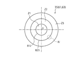
- FIG. 3 is a plan view of the heating unit showing a plurality of heating zones in the heating unit.
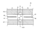
- FIG. 4 is a diagram showing a cross-sectional configuration of the heating unit (first example) at a location indicated by reference symbol “IV” in FIG. 3.
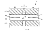
- FIG. 5 is a view showing a cross-sectional configuration of the heating unit (second example).
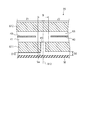
- FIG. 6 is a view showing a cross-sectional configuration of a modification of the heating unit.
- FIG. 7 is a view showing a cross-sectional configuration of another modification of the heating unit.
- FIG. 8 is a flowchart showing a plating process of the substrate in the plating apparatus of FIG.
- FIG. 1 is a schematic view showing a configuration of a plating processing apparatus as an example of a substrate liquid processing apparatus according to an embodiment of the present invention.
- the plating processing apparatus is an apparatus that supplies the plating solution L1 (processing liquid) to the substrate W to perform plating processing (liquid processing) on the substrate W.
- the plating processing apparatus 1 includes a plating processing unit 2 and a control unit 3 that controls the operation of the plating processing unit 2.
- the plating unit 2 performs various processes on the substrate W (wafer). The various processes which the plating process unit 2 performs are mentioned later.
- the control unit 3 is, for example, a computer, and includes an operation control unit and a storage unit.
- the operation control unit is configured of, for example, a CPU (Central Processing Unit), and controls the operation of the plating processing unit 2 by reading and executing a program stored in the storage unit.
- the storage unit is composed of, for example, a storage device such as a random access memory (RAM), a read only memory (ROM), or a hard disk, and stores a program for controlling various processes executed in the plating processing unit 2.
- the program may be recorded on a recording medium 31 readable by a computer, or may be installed from the recording medium 31 in a storage unit.
- Examples of the computer readable recording medium 31 include a hard disk (HD), a flexible disk (FD), a compact disk (CD), a magnet optical disk (MO), and a memory card.
- a program for controlling the plating processing apparatus 1 to execute a plating processing method described later is recorded in the recording medium 31. .
- FIG. 1 is a schematic plan view showing the configuration of the plating unit 2.
- the plating processing unit 2 has a loading and unloading station 21 and a processing station 22 provided adjacent to the loading and unloading station 21.
- the loading / unloading station 21 includes a placement unit 211 and a transport unit 212 provided adjacent to the placement unit 211.
- carriers C accommodating the plurality of substrates W in a horizontal state are placed.
- the transport unit 212 includes a transport mechanism 213 and a delivery unit 214.
- the transport mechanism 213 includes a holding mechanism that holds the substrate W, and is configured to be able to move in the horizontal direction and the vertical direction and to pivot around the vertical axis.
- the processing station 22 includes a plating processing unit 5.
- the number of the plating processing units 5 included in the processing station 22 is two or more, but may be one.
- the plating processing units 5 are arranged on both sides of the transport path 221 extending in a predetermined direction (both sides in the direction orthogonal to the moving direction of the transport mechanism 222 described later).
- the transport mechanism 222 includes a holding mechanism that holds the substrate W, and is configured to be able to move in the horizontal direction and the vertical direction and to pivot around the vertical axis.
- the transport mechanism 213 of the loading / unloading station 21 transports the substrate W between the carrier C and the delivery unit 214. Specifically, the transport mechanism 213 takes out the substrate W from the carrier C placed on the placement unit 211 and places the taken-out substrate W on the delivery unit 214. Further, the transport mechanism 213 takes out the substrate W placed on the delivery unit 214 by the transport mechanism 222 of the processing station 22, and stores the substrate W in the carrier C of the placement unit 211.
- the transport mechanism 222 of the processing station 22 transports the substrate W between the delivery unit 214 and the plating unit 5 and between the plating unit 5 and the delivery unit 214. Specifically, the transport mechanism 222 takes out the substrate W placed on the delivery unit 214 and carries the taken-out substrate W into the plating processing unit 5. Further, the transport mechanism 222 takes out the substrate W from the plating processing unit 5 and places the taken-out substrate W on the delivery unit 214.
- FIG. 2 is a schematic cross-sectional view showing the configuration of the plating processing unit 5.
- the plating processing unit 5 performs a liquid process including an electroless plating process.
- the plating processing unit 5 is disposed on the chamber 51, the substrate holding unit 52 disposed in the chamber 51 and holding the substrate W horizontally, and plating on the upper surface (processing surface Sw) of the substrate W held by the substrate holding unit 52.
- a plating solution supply unit 53 (treatment solution supply unit) for supplying the solution L1 (treatment solution).
- the substrate holding unit 52 has a chuck member 521 that vacuum-sucks the lower surface (rear surface) of the substrate W.
- the substrate holding unit 52 is a so-called vacuum chuck type, but the substrate holding unit 52 is not limited to this, and may be, for example, a mechanical chuck type that holds the outer edge portion of the substrate W by a chuck mechanism or the like.
- a rotation motor 523 (rotation drive unit) is connected to the substrate holding unit 52 via a rotation shaft 522. When the rotation motor 523 is driven, the substrate holding unit 52 rotates with the substrate W.
- the rotary motor 523 is supported by a base 524 fixed to the chamber 51.
- the plating solution supply unit 53 discharges (supplys) the plating solution L1 to the substrate W held by the substrate holding unit 52 (plating solution nozzle 531 (processing solution nozzle)) and plating that supplies the plating solution L1 to the plating solution nozzle 531 And a liquid supply source 532.
- the plating solution supply source 532 supplies the plating solution nozzle 531 with the plating solution L1 that has been heated or adjusted to a predetermined temperature.
- the temperature of the plating solution L1 when discharged from the plating solution nozzle 531 is, for example, 55 ° C. or more and 75 ° C. or less, more preferably 60 ° C. or more and 70 ° C. or less.
- the plating solution nozzle 531 is held by the nozzle arm 56 so as to be movable.
- the plating solution L1 is a plating solution for autocatalytic (reduction) electroless plating.
- the plating solution L1 includes, for example, metal ions such as cobalt (Co) ion, nickel (Ni) ion, tungsten (W) ion, copper (Cu) ion, palladium (Pd) ion, gold (Au) ion, and the like. It contains a reducing agent such as phosphoric acid and dimethylamine borane.
- the plating solution L1 may contain an additive and the like.
- Examples of the plating film (metal film) formed by the plating treatment using the plating solution L1 include CoWB, CoB, CoWP, CoWBP, NiWB, NiB, NiWP, NiWBP and the like.
- the plating processing unit 5 As another processing liquid supply unit, the plating processing unit 5 according to the present embodiment rinses the upper surface of the substrate W with the cleaning liquid supply unit 54 that supplies the cleaning liquid L2 to the upper surface of the substrate W held by the substrate holding unit 52. And a rinse liquid supply unit 55 for supplying the liquid L3.
- the cleaning solution supply unit 54 has a cleaning solution nozzle 541 for discharging the cleaning solution L2 onto the substrate W held by the substrate holding unit 52, and a cleaning solution supply source 542 for supplying the cleaning solution L2 to the cleaning solution nozzle 541.
- the cleaning liquid L2 include organic acids such as formic acid, malic acid, succinic acid, citric acid and malonic acid, and hydrofluoric acid (DHF) diluted to a concentration that does not corrode the surface to be plated of the substrate W.
- An aqueous solution of hydrogen chloride or the like can be used.
- the cleaning solution nozzle 541 is held by the nozzle arm 56 so as to be movable together with the plating solution nozzle 531.
- the rinse liquid supply unit 55 has a rinse liquid nozzle 551 that discharges the rinse liquid L3 onto the substrate W held by the substrate holding unit 52, and a rinse liquid supply source 552 that supplies the rinse liquid L3 to the rinse liquid nozzle 551.
- the rinse solution nozzle 551 is held by the nozzle arm 56 and is movable together with the plating solution nozzle 531 and the cleaning solution nozzle 541.
- pure water can be used as the rinse liquid L3.
- a nozzle moving mechanism (not shown) is connected to the nozzle arm 56 holding the plating solution nozzle 531, the cleaning solution nozzle 541, and the rinse solution nozzle 551 described above.
- the nozzle moving mechanism moves the nozzle arm 56 horizontally and vertically. More specifically, between the discharge position at which the nozzle arm 56 discharges the processing liquid (plating solution L1, cleaning liquid L2 or rinse liquid L3) onto the substrate W by the nozzle moving mechanism, and the retracted position retracted from the discharge position. It is possible to move with.
- the ejection position is not particularly limited as long as the processing liquid can be supplied to any position on the upper surface of the substrate W. For example, it is preferable to set a position where the processing liquid can be supplied to the center of the substrate W as a discharge position.
- the discharge position of the nozzle arm 56 may be different depending on when the rinse liquid L3 is supplied.
- the retracted position is a position in the chamber 51 which does not overlap the substrate W when viewed from above, and is a position separated from the discharge position.
- a cup 571 is provided around the substrate holding unit 52.
- the cup 571 is formed in a ring shape when viewed from above, and receives the processing liquid scattered from the substrate W when the substrate W rotates, and guides the processing liquid to a drain duct 581 described later.
- An atmosphere blocking cover 572 is provided on the outer peripheral side of the cup 571 to suppress the diffusion of the atmosphere around the substrate W into the chamber 51.
- the atmosphere blocking cover 572 is formed in a cylindrical shape so as to extend in the vertical direction, and the upper end is open. A lid 6 described later can be inserted into the atmosphere blocking cover 572 from above.
- a drain duct 581 is provided below the cup 571.
- the drain duct 581 is formed in a ring shape when viewed from above, and receives and discharges the processing liquid received and lowered by the cup 571 and the processing liquid directly lowered from the periphery of the substrate W.
- An inner cover 582 is provided on the inner peripheral side of the drain duct 581.
- the substrate W held by the substrate holding unit 52 is covered by the lid 6.
- the lid 6 has a ceiling 61 and a side wall 62 extending downward from the ceiling 61.
- the ceiling portion 61 is disposed above the substrate W held by the substrate holding portion 52 when the lid 6 is positioned at a lower position described later, and faces the substrate W at a relatively small distance.
- the ceiling portion 61 includes a first ceiling plate 611 and a second ceiling plate 612 provided on the first ceiling plate 611.
- a heater 63 (heating unit) is interposed between the first ceiling plate 611 and the second ceiling plate 612, and the first ceiling plate 611 is provided as a first planar body and a second planar body provided so as to sandwich the heater 63.
- a second ceiling plate 612 is provided.
- the first ceiling plate 611 and the second ceiling plate 612 seal the heater 63 so that the heater 63 does not touch the processing solution such as the plating solution L1.
- a seal ring 613 is provided between the first ceiling plate 611 and the second ceiling plate 612 on the outer peripheral side of the heater 63, and the heater 63 is sealed by the seal ring 613.
- the first ceiling plate 611 and the second ceiling plate 612 preferably have corrosion resistance to a processing solution such as the plating solution L1, and may be made of, for example, an aluminum alloy.
- a processing solution such as the plating solution L1
- the first ceiling plate 611, the second ceiling plate 612 and the side wall portion 62 may be coated with Teflon (registered trademark).
- a lid moving mechanism 7 is connected to the lid 6 via a lid arm 71.
- the lid moving mechanism 7 moves the lid 6 horizontally and vertically. More specifically, the lid moving mechanism 7 has a swing motor 72 for moving the lid 6 in the horizontal direction, and a cylinder 73 (space adjustment unit) for moving the lid 6 in the vertical direction.
- the swing motor 72 is mounted on a support plate 74 provided so as to be movable in the vertical direction with respect to the cylinder 73.
- an actuator (not shown) including a motor and a ball screw may be used.
- the swing motor 72 of the lid moving mechanism 7 moves the lid 6 between an upper position disposed above the substrate W held by the substrate holding unit 52 and a retracted position retracted from the upper position.
- the upper position is a position facing the substrate W held by the substrate holding unit 52 at a relatively large distance, and is a position overlapping the substrate W when viewed from above.
- the retracted position is a position in the chamber 51 which does not overlap the substrate W when viewed from above.
- the cylinder 73 of the lid moving mechanism 7 moves the lid 6 in the vertical direction to adjust the distance between the substrate W on which the plating solution L1 is deposited on the processing surface Sw and the first ceiling plate 611 of the ceiling portion 61. Do. More specifically, the cylinder 73 positions the lid 6 at a lower position (indicated by a solid line in FIG. 2) and at an upper position (indicated by a two-dot chain line in FIG. 2).
- the first ceiling plate 611 When the lid 6 is disposed at the lower position, the first ceiling plate 611 approaches the substrate W. In this case, it is preferable to set the lower position so that the first ceiling plate 611 does not touch the plating solution L1 on the substrate W in order to prevent the contamination of the plating solution L1 and the generation of air bubbles in the plating solution L1. is there.
- the upper position is a height position that can prevent the lid 6 from interfering with surrounding structures such as the cup 571 and the atmosphere blocking cover 572 when the lid 6 is pivoted in the horizontal direction. .
- the heater 63 when the heater 63 is driven and the lid 6 is positioned at the above-described lower position, the plating solution L1 on the substrate W is heated.
- the side wall portion 62 of the lid 6 extends downward from the peripheral portion of the first ceiling plate 611 of the ceiling portion 61, and when heating the plating solution L1 on the substrate W (ie, the lid 6 is positioned at the lower position) Case) is disposed on the outer peripheral side of the substrate W.
- the lower end of the side wall portion 62 may be positioned lower than the substrate W.
- a heater 63 is provided on the ceiling portion 61 of the lid 6.
- the heater 63 heats the processing solution (preferably, the plating solution L1) on the substrate W when the lid 6 is positioned at the lower position.
- the heater 63 is interposed between the first ceiling plate 611 and the second ceiling plate 612 of the lid 6, and is sealed as described above, and the heater 63 is treated with the plating solution L1 or the like. It is prevented from touching the liquid.
- an inert gas for example, nitrogen (N 2 ) gas
- the inert gas supply unit 66 includes a gas nozzle 661 that discharges an inert gas to the inside of the lid 6 and an inert gas supply source 662 that supplies the gas nozzle 661 with the inert gas.
- the gas nozzle 661 is provided on the ceiling portion 61 of the lid 6 and discharges the inert gas toward the substrate W in a state where the lid 6 covers the substrate W.
- the ceiling portion 61 and the side wall portion 62 of the lid 6 are covered by a lid cover 64.
- the lid cover 64 is placed on the second ceiling plate 612 of the lid 6 via the support portion 65. That is, on the second ceiling plate 612, a plurality of support portions 65 projecting upward from the upper surface of the second ceiling plate 612 are provided, and the lid cover 64 is placed on the support portions 65.
- the lid cover 64 is movable together with the lid 6 in the horizontal and vertical directions.
- the lid cover 64 preferably has higher heat insulation than the ceiling portion 61 and the side wall portion 62 in order to suppress heat in the lid 6 from escaping to the periphery.
- the lid cover 64 is preferably made of a resin material, and it is more preferable that the resin material has heat resistance.
- a fan filter unit 59 (gas supply unit) for supplying clean air (gas) around the lid 6 is provided.
- the fan filter unit 59 supplies air into the chamber 51 (particularly, into the atmosphere blocking cover 572), and the supplied air flows toward an exhaust pipe 81 described later.
- a downflow in which the air flows downward is formed around the lid 6, and a gas vaporized from the processing solution such as the plating solution L1 flows toward the exhaust pipe 81 by the downflow.
- the gas vaporized from the processing liquid is prevented from rising and diffusing into the chamber 51.
- the gas supplied from the fan filter unit 59 described above is exhausted by the exhaust mechanism 8.
- the exhaust mechanism 8 has two exhaust pipes 81 provided below the cup 571 and an exhaust duct 82 provided below the drain duct 581.
- the two exhaust pipes 81 penetrate the bottom of the drain duct 581 and communicate with the exhaust duct 82, respectively.
- the exhaust duct 82 is substantially formed in a semicircular ring shape when viewed from above. In the present embodiment, one exhaust duct 82 is provided below the drain duct 581, and two exhaust pipes 81 communicate with the exhaust duct 82.
- the plating solution L1 on the processing surface Sw of the substrate W is heated by the heating unit 35 including the heater 63 and the ceiling portion 61 supporting the heater 63. .
- FIG. 3 is a plan view of the heating unit 35 and shows a plurality of heating zones Z1 to Z3 in the heating unit 35.
- the heating unit 35 has a circular planar shape as a whole, has substantially the same size or a slightly larger size as the processing surface Sw of the substrate W in the horizontal direction, and can cover the entire processing surface Sw of the substrate W.
- the heating unit 35 of the present embodiment includes a first heating zone Z1 having a circular planar shape, a second heating zone Z2 having an annular planar shape surrounding the first heating zone Z1, and an annular shape surrounding the second heating zone Z2. And a third heating zone Z3 having a planar shape of The respective heating zones Z1 to Z3 are provided to heat the processing solution on the processing surface Sw of the substrate W located immediately below when the lid 6 is disposed at the lower position (see the solid line position in FIG. 2). It is done.
- the treatment surface Sw is divided into a plurality of treatment zones (not shown), each of the plurality of treatment zones is assigned a specific heating zone of the heating unit 35, and the treatment liquid is It is heated per treatment zone.
- the first heating zone Z1 mainly heats the processing solution in the processing zone having a circular planar shape based on the center of the processing surface Sw.
- the third heating zone Z3 mainly heats the processing solution on the processing zone (in particular, the processing zone including the outer peripheral portion of the processing surface Sw) having an annular planar shape.
- the second heating zone Z2 mainly heats the processing solution in the processing zone having an annular planar shape between the processing zone to which the first heating zone Z1 is allocated and the processing zone to which the third heating zone Z3 is allocated.
- the planar shape and arrangement of the plurality of heating zones Z1 to Z3 are not limited to the illustrated shape and arrangement.
- the plurality of heating zones Z1 to Z3 are provided with equal widths in the radial direction from the center O, the radial widths of the plurality of heating zones Z1 to Z3 are not necessarily mutually It does not have to be equal to
- the plurality of heating zones Z1 to Z3 are provided concentrically, but, for example, each heating zone may have a rectangular planar shape.
- the above-mentioned names of the first heating zone Z1, the second heating zone Z2 and the third heating zone Z3 are used solely to distinguish the heating zones, and the arrangement relationship of the heating zones is limited. Absent.
- the first heating zone Z1 may be farther from the center of the processing surface Sw than the second heating zone Z2 and the third heating zone Z3, and the first heating zone Z1 to the third heating zone Z3 are not necessarily in the ordinal order You do not have to line up.
- the planar shape and the arrangement of the treatment zone on the treatment surface Sw correspond to the planar shape and the arrangement of the heating zone of the heating unit 35.
- FIG. 4 is a view showing a cross-sectional configuration of the heating unit 35 (first example) at a portion indicated by reference symbol “IV” in FIG.
- the cross-sectional structure in the vicinity of the boundary B23 between the second heating zone Z2 and the third heating zone Z3 will be described as an example, but the boundary B12 between the first heating zone Z1 and the second heating zone Z2 will be described.
- the cross section in the vicinity also has the same structure.
- the heater 63 has a plurality of heating elements 40 provided in each of the plurality of heating zones Z1 to Z3 of the heating unit 35, and a support plate 41 for supporting the heating elements 40.
- the specific configuration of the heating element 40 and the support plate 41 is not limited, and the heater 63 can be configured by a mica heater that is typically a planar heating element, and the support plate 41 is configured by mica (mica) It is also good.
- each heating element 40 is embedded in the support plate 41 in the illustrated heater 63, the installation mode of each heating element 40 with respect to each support plate 41 is not limited.
- each heating element 40 is interposed between a pair of support plates 41. It may be arranged.
- At least one of the first ceiling plate 611 (first planar body) and the second ceiling plate 612 (second planar body) has a groove 45.
- the groove 45 is provided in a region corresponding to the boundary between adjacent heating zones among the plurality of heating zones Z1 to Z3.
- the groove 45 is constituted by a space formed in the first ceiling plate 611 and / or the second ceiling plate 612.
- the specific shape and configuration of the groove 45 are not limited to the illustrated example.
- the groove 45 may be a space which does not penetrate the first ceiling plate 611 and / or the second ceiling plate 612 as shown in FIG. 4 (that is, a space defined by the side wall and the bottom wall).
- the groove 45 may be a space passing through the first ceiling plate 611 and / or the second ceiling plate 612 (that is, a space defined by the side wall) as shown in FIG. 5 described later.
- each of the first ceiling plate 611 and the second ceiling plate 612 has one groove 45 between adjacent heating zones.
- the cross-sectional area in the height direction of the portion where the groove 45 is provided is smaller than the cross-sectional area in the height direction of the portion where the groove 45 is not provided.
- the groove 45 having such a configuration acts as a resistance for heat transfer and suppresses the conduction of heat between adjacent heating zones. That is, the amount of heat conducted is suppressed in the portion where the groove 45 is provided in the first ceiling plate 611 and the second ceiling plate 612 as compared with the portion where the groove 45 is not provided.
- the heating control in units of heating zones is accurately performed. be able to. Therefore, the heating control of the plating solution L1 on the processing surface Sw of the substrate W can be accurately performed in zone units.
- FIG. 5 is a view showing a cross-sectional configuration of the heating unit 35 (second example).
- the elements that are the same as or similar to the heating unit 35 (see FIG. 4) of the first example described above are given the same reference numerals, and detailed descriptions thereof will be omitted.
- the groove 45 provided in the first ceiling plate 611 penetrates the first ceiling plate 611.
- the other configuration of the heating unit 35 shown in FIG. 5 is the same as that of the heating unit 35 shown in FIG.
- the groove 45 of the first ceiling plate 611 completely penetrates the first ceiling plate 611, whereby the first ceiling plate 611 can be completely divided between the heating zones. Thereby, the conduction of heat through the first ceiling plate 611 is blocked by the groove 45, and heat can be effectively prevented from being transmitted between adjacent heating zones. Therefore, it is easy to provide a large temperature difference between adjacent heating zones, and heating control of the processing liquid on the processing surface Sw of the substrate W can be performed with high accuracy in processing zone units. Further, even in the case where a large temperature difference is provided between the heating zones, the thermal stress that can be generated in the first ceiling plate 611 can be effectively reduced by the groove 45 provided as a through hole, and the heating caused by the thermal stress The occurrence of distortion of the unit 35 can be prevented.
- the groove 45 of the second ceiling plate 612 shown in FIG. 5 is opened to the heater 63 side similarly to the groove 45 of the second ceiling plate 612 shown in FIG. 4, and the side opposite to the heater 63 is the second ceiling plate 612. Is closed by The groove 45 of the second ceiling plate 612 may also penetrate through the second ceiling plate 612 similarly to the groove 45 of the first ceiling plate 611. For example, the groove 45 of the second ceiling plate 612 may penetrate through the second ceiling plate 612 while the groove 45 of the first ceiling plate 611 penetrates the first ceiling plate 611. Although the groove 45 of the first ceiling plate 611 does not penetrate the first ceiling plate 611, the groove 45 of the second ceiling plate 612 may penetrate the second ceiling plate 612.
- the second ceiling plate 612 is not completely divided by the groove 45.
- the second ceiling plate 612 contributes less to the heating of the processing liquid on the processing surface Sw than the first ceiling plate 611.
- the groove 45 of the first ceiling plate 611 penetrates the first ceiling plate 611 while the second ceiling
- the groove 45 of the plate 612 preferably does not penetrate through the second ceiling plate 612.
- the inventors of the present invention have repeatedly performed a simulation to consider a temperature difference that may occur between heating zones while changing characteristics such as the shape and arrangement of the groove 45 of the first ceiling plate 611 and / or the second ceiling plate 612.
- temperature differences of about 1 to 2 ° C. may not be applied between adjacent heating zones, but by forming the grooves 45 as through holes between adjacent heating zones.
- a temperature difference of 10 ° C. or more could be added.
- a temperature difference of 30 ° C. or more can be provided between adjacent heating zones by forming the second ceiling plate 612 with a resin thermal insulator and making the groove 45 of the first ceiling plate 611 a through hole. It was also confirmed that there is a case.
- it is very effective to form a large temperature difference between adjacent heating zones, by configuring the groove 45 of the first ceiling plate 611 and / or the second ceiling plate 612 as a through hole.
- each groove 45 shown in FIG. 4 opens in a direction toward the heater 63, but may open in a direction away from the heater 63.
- one of the first ceiling plate 611 and the second ceiling plate 612 (for example, the first ceiling plate 611) has a groove 45 opened in a direction away from the heater 63, and the other (for example, the second ceiling plate 612) is a heater It may have a groove 45 opening in a direction toward 63.
- first ceiling plate 611 and the second ceiling plate 612 may have both the groove 45 opening in the direction away from the heater 63 and the groove 45 opening in the direction toward the heater 63.
- the form of the groove 45 may be determined according to the formation location. For example, the form of the groove 45 provided in the region corresponding to the boundary B12 between the first heating zone Z1 and the second heating zone Z2 and the boundary B23 between the second heating zone Z2 and the third heating zone Z3 The form of the grooves 45 provided in the corresponding regions may be different from each other.
- the first ceiling plate 611 is disposed at a position closer to the processing surface Sw than the second ceiling plate 612 between the heater 63 and the processing surface Sw. Therefore, from the viewpoint of accurately controlling the heating of the plating solution L1 on the processing surface Sw in units of processing zones, at least the first ceiling plate 611 of the first ceiling plate 611 and the second ceiling plate 612 may be provided with the groove 45. preferable. Further, from the viewpoint of efficiently transferring the heat from the heating element 40 to the plating solution L1 on the treated surface Sw, the groove 45 opened in the direction away from the heater 63 is formed in the first ceiling plate 611. It is preferable to increase the surface area of the lower surface to increase the heat dissipation area.
- Each of the first ceiling plate 611 and the second ceiling plate 612 shown in FIGS. 4 and 5 has one groove 45 in the area corresponding to the boundary between the adjacent heating zones.
- the groove 45 may be provided.
- the "area corresponding to the boundary between adjacent heating zones” refers to an area near the boundary defined with reference to the boundary between adjacent heating zones, and a heating element provided in each of the adjacent heating zones An area 40 is not arranged.
- the symbol “B” represents “an area corresponding to the boundary between adjacent heating zones", and one or both ends of the adjacent heating zones are "on the boundary between adjacent heating zones. It may be included in the corresponding area B ".
- the material of the second ceiling plate 612 may be different from the material of the first ceiling plate 611.
- the first ceiling plate 611 is made of a material (for example, an aluminum alloy) excellent in heat transfer performance (especially heat conduction performance and heat radiation performance)
- the heat transfer performance is inferior to the constituent materials of the first ceiling board 611
- the second ceiling plate 612 may be made of a material (for example, resin).
- the radiant heat from the first ceiling plate 611 is directly transmitted to the processing liquid on the processing surface Sw of the substrate W. Therefore, the processing liquid on the processing surface Sw of the substrate W can be efficiently heated by forming the first ceiling plate 611 with a material excellent in heat transfer performance.
- the heat of the second ceiling plate 612 is basically to the treatment liquid on the treatment surface Sw. Can not be transmitted directly.
- the heat of the second ceiling plate 612 is transmitted between the heating zones of the heating unit 35 through the second ceiling plate 612, which may inhibit the formation of a large temperature difference between the heating zones. Therefore, by forming the second ceiling plate 612 with a material having a low heat transfer performance, it is possible to easily make a desired temperature difference between the heating zones of the heating unit 35.
- the filling member 46 may be disposed in the groove 45.
- the filling member 46 is a material (for example, resin or other heat insulation) inferior to the first ceiling plate 611 and the second ceiling plate 612 in heat transfer performance (particularly heat conduction performance). Material) is preferable.
- the groove 45 of the first ceiling plate 611 is a through hole, the first ceiling plate 611 is used to prevent particles from falling through the groove 45 onto the processing surface Sw during processing of the substrate W.
- the filling member 46 is arranged in the groove 45 provided in the. In the heating unit 35 shown in FIG.
- both the groove 45 of the first ceiling plate 611 and the groove 45 of the second ceiling plate 612 are through holes, and the whole of each of the grooves 45 is made of a heat insulating material.
- the filling member 46 is filled. In this case, it is possible to prevent the heat transfer between the heating zones while securing the strength of the heating unit 35, and to easily provide a large temperature difference between the heating zones.
- the filling member 46 may not necessarily fill the entire groove 45, and may be disposed only in a part of the groove 45. Also, the filling member 46 may be disposed in the groove 45 (see FIG. 4) which is not a through hole.
- the distance between the first ceiling plate 611 and the processing surface Sw of the substrate W may be different from each other. That is, the first ceiling plate 611 in a certain heating zone may project further to the processing surface Sw side (that is, the lower side in FIG. 7) of the substrate W than the first ceiling plate 611 in one or more other heating zones. In this case, the surface on the treated surface Sw side of the first ceiling plate 611 in a certain heating zone is closer to the treated surface Sw than the surface on the treated surface Sw side of the first ceiling plate 611 in one or more other heating zones. It can be arranged. As the first ceiling plate 611 is closer to the processing surface Sw, the processing liquid on the processing surface Sw is efficiently heated. Accordingly, by changing the distance between the first ceiling plate 611 and the processing surface Sw of the substrate W between the heating zones, the heating efficiency of the processing liquid can be changed for each processing zone.
- the distance (also referred to as “first heating interval”) D1 between the first ceiling plate 611 and the processing surface Sw in the first heating zone Z1 is the distance between the first ceiling plate 611 and the treatment in the second heating zone Z2.
- the distance to the surface Sw (also referred to as “second heating interval”) D2 is smaller (D1 ⁇ D2). Therefore, the temperature of the processing liquid in the processing zone corresponding to the first heating zone Z1 is more likely to be raised by the heating unit 35 than the temperature of the processing liquid in the processing zone corresponding to the second heating zone Z2.
- the distance (also referred to as “third heating interval”) D3 between the first ceiling plate 611 and the processing surface Sw in the third heating zone Z3 is the first heating interval D1 and / or Alternatively, it may be different from the second heating interval D2.
- the heating interval of the heating zone corresponding to the treatment zone in which the temperature of the treatment liquid hardly rises (for example, the first heating interval D1 and / or the third heating interval D3) Is preferably smaller than the heating intervals (for example, the second heating interval D2) of the other heating zones.
- Control of heating unit 35 is performed by control part 3 (refer to Drawing 1).
- the third The calorific value from the heating element 40 disposed in the heating zone Z3 is larger than the calorific value from the heating element 40 disposed in the first heating zone Z1.
- a temperature detection sensor such as an infrared sensor capable of measuring the temperature of the plating solution L1 on the processing surface Sw for each processing zone may be installed.
- the control unit 3 may control the calorific value of each heating element 40 (for example, the electric power supplied to each heating element 40) based on the detection result of the temperature detection sensor.
- the plating method implemented by the plating apparatus 1 includes a plating process on the substrate W.
- the plating process is performed by the plating unit 5.
- the operation of the plating processing unit 5 described below is controlled by the control unit 3. During the following processing, clean air is supplied from the fan filter unit 59 into the chamber 51 and flows toward the exhaust pipe 81.
- the substrate W is carried into the plating processing unit 5, and the substrate W is held horizontally by the substrate holding unit 52 (step S1).
- step S2 cleaning processing of the substrate W held by the substrate holding unit 52 is performed (step S2).
- the rotary motor 523 is first driven to rotate the substrate W at a predetermined number of rotations, and then the nozzle arm 56 positioned at the retracted position is moved to the discharge position, and the rotating substrate W is cleaned
- the cleaning liquid L2 is supplied from the nozzle 541 to clean the surface of the substrate W.
- the cleaning liquid L2 supplied to the substrate W is discharged to the drain duct 581.
- a rinse process is performed on the substrate W (step S3).
- the rinse solution L3 is supplied from the rinse solution nozzle 551 to the rotating substrate W to rinse the surface of the substrate W.
- the cleaning liquid L2 remaining on the substrate W is washed away.
- the rinse liquid L3 supplied to the substrate W is discharged to the drain duct 581.
- a plating solution application step of forming a paddle of the plating solution L1 on the processing surface Sw of the substrate W is performed (step S4).
- the number of rotations of the substrate W is reduced compared to the number of rotations at the time of the rinse process, and for example, the number of rotations of the substrate W may be 50 to 150 rpm. Thereby, the plating film formed on the substrate W can be made uniform.
- the amount of deposition of the plating solution L1 may be increased by stopping the rotation of the substrate W.
- the plating solution L1 is discharged from the plating solution nozzle 531 to the upper surface (that is, the processing surface Sw) of the substrate W.
- the plating solution L1 remains on the treated surface Sw due to surface tension, and a layer (so-called paddle) of the plating solution L1 is formed. A portion of the plating solution L1 flows out of the processing surface Sw and is discharged through the drain duct 581. After the predetermined amount of plating solution L1 is discharged from the plating solution nozzle 531, the discharge of the plating solution L1 is stopped. Thereafter, the nozzle arm 56 is positioned at the retracted position.
- a plating solution heat treatment step the plating solution L1 deposited on the substrate W is heated.
- a process of covering the substrate W with the cover 6 step S5), a process of supplying an inert gas (step S6), and the process of arranging the cover 6 at a lower position
- a heating step (step S7) of heating and a step (step S8) of retracting the lid 6 from above the substrate W are included.
- the number of rotations of the substrate W is preferably maintained at the same speed (or the rotation stop) as the plating solution deposition step.
- step S5 In the step of covering the substrate W with the lid 6 (step S5), first, the swing motor 72 of the lid moving mechanism 7 is driven to horizontally move the lid 6 positioned at the retracted position in the horizontal direction. It is located at the upper position. Subsequently, the cylinder 73 of the lid moving mechanism 7 is driven, and the lid 6 positioned at the upper position is lowered and positioned at the lower position, and the substrate W is covered by the lid 6 and the periphery of the substrate W Space is blocked.
- an inert gas is discharged from the gas nozzle 661 provided on the ceiling 61 of the lid 6 to the inside of the lid 6 (step S6).
- the air inside the lid 6 is replaced with the inert gas, and the periphery of the substrate W becomes a low oxygen atmosphere.
- the inert gas is discharged for a predetermined time, and then the discharge of the inert gas is stopped.
- the plating solution L1 deposited on the substrate W is heated (step S7).
- the temperature of the plating solution L1 rises to a temperature at which the component in the plating solution L1 precipitates, the component of the plating solution L1 precipitates on the upper surface of the substrate W to form and grow a plating film.
- the plating solution L1 is heated and maintained at the deposition temperature for a time necessary to obtain a plating film having a desired thickness.
- the lid moving mechanism 7 is driven to position the lid 6 at the retracted position (step S8).
- the plating solution heat treatment process steps S5 to S8 of the substrate W is completed.
- the substrate W is rinsed (step S9).
- this rinse process first, the number of rotations of the substrate W is increased more than the number of rotations during the plating process, and the substrate W is rotated at the same number of rotations as the substrate rinsing process (step S3) before the plating process, for example.
- the rinse liquid nozzle 551 positioned at the retracted position is moved to the discharge position.
- the rinse solution L3 is supplied from the rinse solution nozzle 551 to the rotating substrate W, the surface of the substrate W is cleaned, and the plating solution L1 remaining on the substrate W is washed away.
- the substrate W is dried (step S10).
- the substrate W is rotated at a high speed, and, for example, the number of rotations of the substrate W is increased more than the number of rotations of the substrate rinsing process (step S9).
- the rinse liquid L3 remaining on the substrate W is shaken off and removed, and the substrate W on which the plating film is formed is obtained.
- drying of the substrate W may be promoted by blowing an inert gas such as nitrogen (N 2 ) gas onto the substrate W.
- the substrate W is taken out of the substrate holding unit 52 and carried out of the plating processing unit 5 (step S11).
- step S7 particularly when the plating solution L1 on the processing surface Sw of the substrate W is heated (step S7), the energized state of the heating element 40 in each heating zone of the heater 63 divided by the groove 45 Is controlled by the control unit 3, and heating control of the plating solution L1 on the processing surface Sw is performed in zone units.
- the heating control of the plating solution L1 on the substrate W is accurately performed in zone units by providing the grooves 45 in the region corresponding to the boundary between adjacent heating zones in the heater 63. be able to.
- the groove 45 in the first ceiling plate 611 disposed between the heater 63 and the substrate W in particular, the processing surface Sw
- the amount of heat emitted from the heater 63 toward the substrate W is effective for each heating zone Can be changed.
- the groove 45 so as to open in the direction toward the heater 63, the surface area of the portion of the first ceiling plate 611 and / or the second ceiling plate 612 facing the heater 63 can be increased. It can receive efficiently the radiation of the heat emitted from 63. Also, the exposed surface (i.e., the lower surface) of the first ceiling plate 611 and the exposed surface (i.e., the upper surface) of the second ceiling plate 612 can be formed flat.
- the groove 45 so as to open in a direction away from the heater 63, it is possible to increase the surface area exposed outward, and the heat generated by the heater 63 (particularly each heating element 40) is efficiently It can be transmitted outside.
- the heat conduction between the heating zones can be more effectively suppressed, and the surface area can be further increased.
- the process of forming the groove 45 in the first ceiling plate 611 and / or the second ceiling plate 612 can be performed relatively easily, and the heating unit 35 can be configured simply. Furthermore, a general-purpose device such as a mica heater can be used as the heater 63, and the heating unit 35 can be configured inexpensively.
- the present invention is not limited to the above embodiment and modification as it is, and at the implementation stage, the constituent elements can be modified and embodied without departing from the scope of the invention. Further, various inventions can be formed by appropriate combinations of a plurality of constituent elements disclosed in the above-described embodiment and modification. Some components may be deleted from all the components shown in the embodiment and the modification. Furthermore, components in different embodiments and variations may be combined as appropriate.
- the substrate liquid processing apparatus and the substrate liquid processing method according to the present invention are effective for processing liquids other than the plating liquid L1 and liquid processing other than the plating processing.
- a program that when executed by a computer for controlling the operation of the substrate liquid processing apparatus (plating processing apparatus 1), the computer controls the substrate liquid processing apparatus to execute the above-described substrate liquid processing method.
- the present invention may be embodied as a recorded recording medium (for example, the recording medium 31 of the control unit 3).
Landscapes
- Chemical & Material Sciences (AREA)
- General Chemical & Material Sciences (AREA)
- Chemical Kinetics & Catalysis (AREA)
- Engineering & Computer Science (AREA)
- Materials Engineering (AREA)
- Mechanical Engineering (AREA)
- Metallurgy (AREA)
- Organic Chemistry (AREA)
- Inorganic Chemistry (AREA)
- Chemically Coating (AREA)
- Cleaning Or Drying Semiconductors (AREA)
Abstract
Description
上述のように本実施形態のめっき処理部5では、ヒータ63と当該ヒータ63を支持する天井部61とを具備する加熱ユニット35によって、基板Wの処理面Sw上のめっき液L1が加熱される。
図5は、加熱ユニット35(第2の例)の断面構成を示す図である。本例において、上述の第1の例の加熱ユニット35(図4参照)と同一又は類似の要素については、同じ符号を付し、詳細な説明は省略する。
なお、溝45は図4及び図5に示す形態には限定されず、様々な形態で第1天井板611及び/又は第2天井板612に設けられることが可能である。例えば図4に示す各溝45は、ヒータ63に向かう方向に開口するが、ヒータ63から遠ざかる方向に開口していてもよい。また第1天井板611及び第2天井板612のうちの一方(例えば第1天井板611)がヒータ63から遠ざかる方向に開口する溝45を有し、他方(例えば第2天井板612)がヒータ63に向かう方向に開口する溝45を有していてもよい。また第1天井板611及び第2天井板612のうちの少なくとも一方が、ヒータ63から遠ざかる方向に開口する溝45及びヒータ63に向かう方向に開口する溝45の両者を有していてもよい。また形成場所に応じて溝45の形態を決めてもよい。例えば、第1加熱ゾーンZ1と第2加熱ゾーンZ2との間の境界B12に対応する領域に設けられる溝45の形態と、第2加熱ゾーンZ2と第3加熱ゾーンZ3との間の境界B23に対応する領域に設けられる溝45の形態とを、互いに異ならせてもよい。
35 加熱ユニット
45 溝
52 基板保持部
53 めっき液供給部
63 ヒータ
611 第1天井板
612 第2天井板
L1 めっき液
Sw 処理面
W 基板
Z1 第1加熱ゾーン
Z2 第2加熱ゾーン
Z3 第3加熱ゾーン
Claims (9)
- 処理液によって基板の処理面の液処理を行う基板液処理装置であって、
前記基板を保持する基板保持部と、
前記基板保持部により保持された前記基板の前記処理面に前記処理液を供給する処理液供給部と、
前記処理面上の前記処理液を加熱する加熱ユニットと、を備え、
前記加熱ユニットは、ヒータと、前記ヒータを挟むようにして設けられる第1面状体及び第2面状体と、を有し、
前記第1面状体は、前記ヒータと前記処理面との間に配置され、
前記ヒータは、前記加熱ユニットの複数の加熱ゾーンのそれぞれに設けられる複数の発熱体を有し、
前記第1面状体及び前記第2面状体のうちの少なくともいずれか一方は溝を有し、当該溝は、前記複数の加熱ゾーンのうちの隣接する加熱ゾーン間の境界に対応する領域に設けられる基板液処理装置。 - 前記溝は、前記第1面状体及び前記第2面状体のうち少なくとも前記第1面状体に設けられている請求項1に記載の基板液処理装置。
- 前記溝は、前記ヒータに向かう方向に開口する請求項1又は2に記載の基板液処理装置。
- 前記溝は、前記ヒータから遠ざかる方向に開口する請求項1又は2に記載の基板液処理装置。
- 前記溝は、隣接する加熱ゾーン間の境界に対応する領域において複数設けられる請求項1~4のいずれか一項に記載の基板液処理装置。
- 前記ヒータは、前記複数の発熱体を支持する支持プレートを有し、
前記支持プレートは、マイカによって構成される請求項1~5のいずれか一項に記載の基板液処理装置。 - 前記第1面状体に設けられている前記溝は、前記第1面状体を貫通している請求項2に記載の基板液処理装置。
- 前記第1面状体に設けられている前記溝に配置されている充填部材を更に備える請求項7に記載の基板液処理装置。
- 前記複数の加熱ゾーンのうちの少なくとも2つの加熱ゾーンにおいて、前記第1面状体と前記処理面との間の間隔がお互いに異なる請求項1~8のいずれか一項に記載の基板液処理装置。
Priority Applications (3)
| Application Number | Priority Date | Filing Date | Title |
|---|---|---|---|
| JP2019557222A JP6926233B2 (ja) | 2017-12-01 | 2018-11-27 | 基板液処理装置 |
| US16/768,245 US11441225B2 (en) | 2017-12-01 | 2018-11-27 | Substrate liquid processing apparatus |
| KR1020207018462A KR102770925B1 (ko) | 2017-12-01 | 2018-11-27 | 기판 액 처리 장치 |
Applications Claiming Priority (4)
| Application Number | Priority Date | Filing Date | Title |
|---|---|---|---|
| JP2017-231745 | 2017-12-01 | ||
| JP2017231745 | 2017-12-01 | ||
| JP2018203794 | 2018-10-30 | ||
| JP2018-203794 | 2018-10-30 |
Publications (1)
| Publication Number | Publication Date |
|---|---|
| WO2019107331A1 true WO2019107331A1 (ja) | 2019-06-06 |
Family
ID=66665004
Family Applications (1)
| Application Number | Title | Priority Date | Filing Date |
|---|---|---|---|
| PCT/JP2018/043496 Ceased WO2019107331A1 (ja) | 2017-12-01 | 2018-11-27 | 基板液処理装置 |
Country Status (4)
| Country | Link |
|---|---|
| US (1) | US11441225B2 (ja) |
| JP (1) | JP6926233B2 (ja) |
| KR (1) | KR102770925B1 (ja) |
| WO (1) | WO2019107331A1 (ja) |
Citations (6)
| Publication number | Priority date | Publication date | Assignee | Title |
|---|---|---|---|---|
| JPS6128617U (ja) * | 1984-07-27 | 1986-02-20 | 日産自動車株式会社 | 射出成形金型の2次スプル−ブツシユ |
| JPH10249891A (ja) * | 1997-03-07 | 1998-09-22 | Sumitomo Heavy Ind Ltd | 射出成形機の射出ノズル |
| JP2002129344A (ja) * | 2000-10-26 | 2002-05-09 | Ebara Corp | 無電解めっき装置 |
| JP2005060792A (ja) * | 2003-08-18 | 2005-03-10 | Tokyo Electron Ltd | 無電解メッキ装置および無電解メッキ方法 |
| JP2017082290A (ja) * | 2015-10-28 | 2017-05-18 | 東京エレクトロン株式会社 | めっき処理装置及びめっき処理方法 |
| JP2018003097A (ja) * | 2016-07-01 | 2018-01-11 | 東京エレクトロン株式会社 | 基板液処理装置、基板液処理方法および記録媒体 |
Family Cites Families (10)
| Publication number | Priority date | Publication date | Assignee | Title |
|---|---|---|---|---|
| JPS6128617A (ja) | 1984-07-18 | 1986-02-08 | Penta Ocean Constr Co Ltd | 鋼製杭の打込み固定工法 |
| JP3250090B2 (ja) | 1995-06-27 | 2002-01-28 | 東京エレクトロン株式会社 | 洗浄処理装置及び洗浄処理方法 |
| US6858084B2 (en) * | 2000-10-26 | 2005-02-22 | Ebara Corporation | Plating apparatus and method |
| KR100756107B1 (ko) * | 2001-02-09 | 2007-09-05 | 동경 엘렉트론 주식회사 | 성막 장치 |
| JP3982402B2 (ja) * | 2002-02-28 | 2007-09-26 | 東京エレクトロン株式会社 | 処理装置及び処理方法 |
| JP3495033B1 (ja) | 2002-09-19 | 2004-02-09 | 東京エレクトロン株式会社 | 無電解メッキ装置、および無電解メッキ方法 |
| KR20070058310A (ko) | 2005-12-02 | 2007-06-08 | 도쿄 엘렉트론 가부시키가이샤 | 무전해 도금 장치 및 무전해 도금 방법 |
| KR100809595B1 (ko) * | 2006-09-13 | 2008-03-04 | 세메스 주식회사 | 박막 히터 및 박막 히터를 제조하는 방법 |
| JP5938164B2 (ja) * | 2011-02-21 | 2016-06-22 | 東京エレクトロン株式会社 | 成膜方法、成膜装置、半導体装置及びその製造方法 |
| JP5788349B2 (ja) * | 2012-03-19 | 2015-09-30 | 東京エレクトロン株式会社 | めっき処理装置、めっき処理方法および記憶媒体 |
-
2018
- 2018-11-27 JP JP2019557222A patent/JP6926233B2/ja active Active
- 2018-11-27 US US16/768,245 patent/US11441225B2/en active Active
- 2018-11-27 KR KR1020207018462A patent/KR102770925B1/ko active Active
- 2018-11-27 WO PCT/JP2018/043496 patent/WO2019107331A1/ja not_active Ceased
Patent Citations (6)
| Publication number | Priority date | Publication date | Assignee | Title |
|---|---|---|---|---|
| JPS6128617U (ja) * | 1984-07-27 | 1986-02-20 | 日産自動車株式会社 | 射出成形金型の2次スプル−ブツシユ |
| JPH10249891A (ja) * | 1997-03-07 | 1998-09-22 | Sumitomo Heavy Ind Ltd | 射出成形機の射出ノズル |
| JP2002129344A (ja) * | 2000-10-26 | 2002-05-09 | Ebara Corp | 無電解めっき装置 |
| JP2005060792A (ja) * | 2003-08-18 | 2005-03-10 | Tokyo Electron Ltd | 無電解メッキ装置および無電解メッキ方法 |
| JP2017082290A (ja) * | 2015-10-28 | 2017-05-18 | 東京エレクトロン株式会社 | めっき処理装置及びめっき処理方法 |
| JP2018003097A (ja) * | 2016-07-01 | 2018-01-11 | 東京エレクトロン株式会社 | 基板液処理装置、基板液処理方法および記録媒体 |
Also Published As
| Publication number | Publication date |
|---|---|
| JP6926233B2 (ja) | 2021-08-25 |
| US20210172066A1 (en) | 2021-06-10 |
| KR20200094760A (ko) | 2020-08-07 |
| JPWO2019107331A1 (ja) | 2020-12-03 |
| US11441225B2 (en) | 2022-09-13 |
| KR102770925B1 (ko) | 2025-02-21 |
Similar Documents
| Publication | Publication Date | Title |
|---|---|---|
| JP6736386B2 (ja) | 基板液処理装置、基板液処理方法および記録媒体 | |
| JP7720888B2 (ja) | 基板処理装置および基板処理方法 | |
| KR102629524B1 (ko) | 기판 액 처리 장치, 기판 액 처리 방법 및 기록 매체 | |
| JP7221414B2 (ja) | 基板液処理方法および基板液処理装置 | |
| WO2019107331A1 (ja) | 基板液処理装置 | |
| WO2019116939A1 (ja) | 基板液処理装置 | |
| JP7267470B2 (ja) | 基板処理方法および基板処理装置 | |
| WO2019107330A1 (ja) | 基板液処理装置、基板液処理方法および記録媒体 | |
| JP7090710B2 (ja) | 基板液処理装置および基板液処理方法 | |
| TWI846928B (zh) | 基板液處理方法、基板液處理裝置、及電腦可讀取記錄媒體 | |
| TWI868153B (zh) | 基板處理方法及基板處理裝置 | |
| WO2020100804A1 (ja) | 基板液処理装置及び基板液処理方法 | |
| KR20230170941A (ko) | 기판 처리 방법, 기판 처리 장치 및 기억 매체 | |
| WO2022168614A1 (ja) | めっき処理方法およびめっき処理装置 |
Legal Events
| Date | Code | Title | Description |
|---|---|---|---|
| 121 | Ep: the epo has been informed by wipo that ep was designated in this application |
Ref document number: 18884617 Country of ref document: EP Kind code of ref document: A1 |
|
| ENP | Entry into the national phase |
Ref document number: 2019557222 Country of ref document: JP Kind code of ref document: A |
|
| NENP | Non-entry into the national phase |
Ref country code: DE |
|
| ENP | Entry into the national phase |
Ref document number: 20207018462 Country of ref document: KR Kind code of ref document: A |
|
| 122 | Ep: pct application non-entry in european phase |
Ref document number: 18884617 Country of ref document: EP Kind code of ref document: A1 |