WO2019107308A1 - バルーンカテーテル - Google Patents
バルーンカテーテル Download PDFInfo
- Publication number
- WO2019107308A1 WO2019107308A1 PCT/JP2018/043378 JP2018043378W WO2019107308A1 WO 2019107308 A1 WO2019107308 A1 WO 2019107308A1 JP 2018043378 W JP2018043378 W JP 2018043378W WO 2019107308 A1 WO2019107308 A1 WO 2019107308A1
- Authority
- WO
- WIPO (PCT)
- Prior art keywords
- balloon
- end side
- inner balloon
- catheter
- distal end
- Prior art date
Links
Images


Classifications
-
- A—HUMAN NECESSITIES
- A61—MEDICAL OR VETERINARY SCIENCE; HYGIENE
- A61M—DEVICES FOR INTRODUCING MEDIA INTO, OR ONTO, THE BODY; DEVICES FOR TRANSDUCING BODY MEDIA OR FOR TAKING MEDIA FROM THE BODY; DEVICES FOR PRODUCING OR ENDING SLEEP OR STUPOR
- A61M25/00—Catheters; Hollow probes
- A61M25/10—Balloon catheters
Definitions
- the present invention relates to a balloon catheter used in a treatment for dilating a stenosis in a body cavity.
- a balloon catheter is widely used for treatment for dilation of a constricted part generated in a body cavity.
- the balloon catheter has a double balloon structure and is configured for fixation and expansion.
- the balloon catheter 1 for esophagus dilation is provided with an inner balloon 3 which is spherically expanded on the outer peripheral surface of the tube main body 2 for fixation, and is expanded into a long rod shape back and forth so as to surround the outside.
- An outer balloon 4 was provided for dilation.
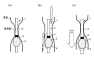
- the catheter 1 In the swallowing training procedure for patients with dysphagia using the balloon catheter 1, first, as shown in FIG. 7A, the catheter 1 is inserted from the oral cavity into the esophagus under fluoroscopy. At this time, since the imaging ring 5 is provided on the catheter 1, it can be confirmed whether the inner balloon 3 has passed through the narrow portion of the esophagus. Then, when the inner balloon 3 passes through the narrowing portion of the esophagus, the inner balloon 3 is expanded and fixed to the narrowing portion.
- the outer balloon 4 is expanded while pulling the tube main body 2 slightly upward (oral side) so that the inner balloon 3 fixed to the narrowed portion does not shift downward (stomach side). .
- the outer balloon 4 is wedge-shaped and its expansion causes the entire balloon to spread and provide pressure stimulation to the stenosis.
- the content (air) of the outer balloon 4 is shifted downward, and the position of the entire outer balloon 4 is displaced. There was a problem.
- patent document 1 As a prior art which can solve the problem mentioned above, what was disclosed by patent document 1, for example is known. That is, while providing a plurality of inner balloons axially spaced from each other on the outer peripheral surface of the tube main body, and covering each inner balloon, and providing an outer balloon portion which can be easily expanded from each inner balloon It is. According to such a balloon catheter, the narrowed portion fits in the valley portion of both inner balloons, and it is possible to prevent positional deviation even if the outer balloon is expanded.
- the present invention has been made focusing on the problems of the prior art as described above, and the number of balloons is only two, the inner side and the outer side, and the simple configuration causes no cost increase. It is another object of the present invention to provide a balloon catheter which can be easily operated with easy operation and requires less labor and time and reliably prevents displacement when expanding a constriction in a body cavity.
- a longitudinally extending and flexible tube body is provided, and the circumferential surface on the way of the tube body is provided with a circumferentially expandable inner balloon and is circumferentially expandable in a state surrounding the inner balloon
- an outer balloon The distal end side of the outer balloon, which is forward in the advancing direction of the tube main body, is close to the same distal end side of the inner balloon, and the proximal end which is backward of the advancing direction of the tube main body is the same proximal end of the inner balloon.
- the balloon catheter is characterized in that the outer balloon is provided in a tapered shape in which the outer diameter on the proximal side of the distal end side in contact with the distal end side of the inner balloon expanded similarly is gradually enlarged.
- the inner balloon is in close contact with the outer peripheral surface of the tube body during contraction;
- the portion covering the inner balloon including the distal end is in intimate contact with the inner balloon, and the portion not covering the inner balloon including the proximal end is in intimate contact with the outer peripheral surface of the tube body.
- the body cavity is an esophagus, which is used for dilation of the esophagus entrance of patients with dysphagia. [1], [2], [3], [4], [5] ] Or the balloon catheter as described in [6].
- the tube body is provided with two balloons, an inner balloon and an outer balloon surrounding the inner balloon.
- the distal end of the outer balloon is close to the distal end of the inner balloon, and the proximal end extends rearward from the proximal end of the inner balloon.
- the distal end of the outer balloon overlaps with the distal end of the inner balloon, but the proximal end of the outer balloon does not overlap with the inner balloon.
- the outer balloon When the outer balloon is expanded, its distal end is in contact with the distal end of the similarly expanded inner balloon. Therefore, the contents (fluid) of the outer balloon do not move forward from the tip side of the inner balloon.
- the outer diameter of the proximal end side gradually becomes larger than that of the distal end side in a tapered shape. Therefore, even if the proximal end of the outer balloon, which does not overlap with the inner balloon, is pressed against the narrow portion in the body cavity, the contents of the outer balloon are less likely to move distally than the proximal end of the outer balloon itself.
- the outer balloon is not deformed and misaligned from the stenosis.
- the outer balloon is formed to have a thinner wall thickness on the proximal side than on the distal side.
- the outer balloon is more likely to expand proximally than distally when expanding to fill the fluid. Therefore, even if the outer balloon is not previously formed into the tapered shape, it is also possible to make it into a tapered shape according to the difference in the degree of expansion due to the internal pressure.
- the inner balloon adheres to the outer peripheral surface of the tube main body at the time of contraction. Also, when the outer balloon is contracted, the portion covering the inner balloon including the distal end is in intimate contact with the inner balloon, and the portion not covering the inner balloon including the proximal end is in intimate contact with the outer peripheral surface of the tube body.
- the term "adhesion" includes not only a state in which there is no gap in the entire circumference of each balloon, but also a state in which even if some wrinkles occur due to the larger outer diameter of the proximal end .
- the imaging marker is provided on the proximal side of the inner balloon, when the tube main body is inserted toward the narrowed portion in the body cavity, the inner balloon The position can be easily confirmed.
- the tube main body is provided with the depth mark starting from the contrast marker in the axial direction, when the tube main body is inserted toward the stenosis portion in the body cavity, The length of the tube body inserted into the body cavity can be easily confirmed.
- the tube main body is provided with the contrast line extending in the axial direction, when inserting the tube main body toward the narrowed portion in the body cavity, the body cavity under radioscopy etc. The position of the entire tube body in the inside can be easily confirmed.
- the above-mentioned balloon catheter can be used optimally for dilation of the esophagus entrance of patients with dysphagia, for example, as described in the above-mentioned [7], as an apparatus for dilating a constriction in the esophagus.
- the simple configuration does not lead to an increase in cost, and the operation is simple, and it does not take time and effort. It can be prevented and the treatment can be performed easily.
- the balloon catheter 10 which concerns on this Embodiment is a medical instrument used for the treatment which dilates the stenosis part in a body cavity.
- the balloon catheter 10 will be described as an example of using the balloon catheter 10 for dilation of the esophagus entrance of a patient with dysphagia, as an apparatus for dilating a stenosis in the esophagus.
- the balloon catheter 10 is provided with a longitudinally extending flexible tube body 11 and an inner circumferential balloon 20 is provided on the outer circumferential surface of the tube body 11 in the circumferential direction. And a circumferentially expandable outer balloon 30 is provided so as to surround the inner balloon 20.
- Each balloon 20, 30 is disposed on the front end side (left side in FIG. 1) which is the front side in the approach direction of the tube main body 11, and is proximal end side (the right side in FIG.
- the catheter head 40 is disposed on the
- the tube body 11 is an elongated tubular member which can be freely curved.
- the material of the tube main body 11 is, for example, a flexible synthetic resin such as silicone rubber or soft polyvinyl chloride.
- the main lumen 12 of the main conduit and the two sub lumens 13 and 14 for supplying fluid for expanding the balloons 20 and 30 are axially separated as independent conduits. It is formed to extend.
- the main lumen 12 is for introducing a chemical solution such as a contrast agent or a nutrient or for aspirating saliva, and is formed as a conduit extending around the axial center of the tube main body 11.
- the tip of the main lumen 12 is open to the outside from the tip of the tube body 11.
- the proximal end of the main lumen 12 communicates with the inside of a catheter head 40 described later.
- One sub-lumen 13 is for passing a fluid (for example, air, sterile distilled water or the like) for expanding the inner balloon 20 described later, and a thin tube extending in the axial direction at a position eccentric from the axial center of the tube main body 11 It is formed as a road.
- the tip end of the sub-lumen 13 is sealed, and the tip end side is opened from the outer peripheral surface of the tube main body 11 and communicates with the inside of the inner balloon 20 (see FIG. 2).
- the proximal end of the sub lumen 13 communicates with the inside of a catheter head 40 described later.
- the other sub-lumen 14 is for passing a fluid (for example, air, sterile distilled water, etc.) for expanding the outer balloon 30 described later, and an axis on the opposite side of the sub-lumen 13 with the main lumen 12 in between. It is formed as an axially extending thin channel at a position off-center from the center.
- the tip of the sub-lumen 14 is also sealed, and the tip end side is opened from the outer peripheral surface of the tube body 11 and is in communication with the inside of the outer balloon 30 (see FIG. 2).
- the proximal end of the sub-lumen 14 communicates with the inside of a catheter head 40 described later.
- a contrast line 15 is provided so as to extend in the axial direction in a vacant space other than the main lumen 12 and the respective sub lumens 13 and 14.
- the contrast line 15 is for confirming the position of the entire tube body 11 from outside the body under the perspective of radiation (for example, X-ray), and is formed to include a material that does not transmit radiation such as barium sulfate, for example. There is. Although a part of the contrast line 15 in FIG. 3 is shown only on the proximal end side of the tube main body 11, it actually extends to the tip of the tube main body 11.
- a contrast marker 16 is provided on the proximal end side of the inner balloon 20 on the distal end side of the tube main body 11.
- the contrast marker 16 is also formed so as to be able to confirm its position from outside the body under the perspective of radiation (for example, X-rays) and includes a material which does not transmit radiation, such as barium sulfate.
- the contrast marker 16 is provided in a ring shape that goes around the outer peripheral surface of the tube main body 11 at a position connected to the proximal end of the inner balloon 20.
- the contrast marker 16 may be formed as part of the proximal side of the inner balloon 20.
- a depth mark 17 starting from the contrast marker 16 is marked on the tube body 11 in the axial direction.
- the depth mark 17 is a scale for confirming the length of the tube body 11 inserted into the body cavity, and is marked by printing or engraving. Although only a part of the depth mark 17 is shown in FIG. 3, it is preferable to draw a scale in the range of 5 to 35 mm, for example.
- the depth mark 17 may be written not only on the outer peripheral surface of the tube main body 11 but also on the inner peripheral surface, or may be provided inside the peripheral wall.
- the inner balloon 20 is disposed on the distal end side of the tube main body 11 and is expandable in a state of covering the entire circumference of the tube main body 11 in the middle.
- flange-like adhesion margins 21 and 22 fixed to the outer peripheral surface of the tube main body 11 are provided on the distal end side and the proximal end side of the inner balloon 20, respectively.
- the opening 13a of the sub-lumen 13 is provided on the inner side of the sub-lumen.
- the material of the inner balloon 20 may be a flexible and elastically deformable material, and, for example, silicone rubber is suitable.
- the inner balloon 20 expands or contracts around the tube body 11 by pressurizing or depressurizing the fluid through the sub-lumen 13.
- the inner balloon 20 is expanded into a spherical shape which is slightly crushed back and forth centering on the tube body 11 when the fluid is introduced from the sub-lumen 13 (see FIG. 2), and the fluid is discharged from the sub-lumen 13 When the reduced pressure operation is performed, it contracts so as to be in close contact with the outer peripheral surface of the tube body 11 (see FIG. 3).
- the outer balloon 30 is provided on the distal end side of the tube main body 11 so as to be expandable in the circumferential direction so as to surround the inner balloon 20.
- flange-shaped adhesion margins 31 and 32 are also provided on the distal end side and the proximal end side of the outer balloon 30, respectively.
- An opening 14a is provided.
- the material of the outer balloon 30 may also be a flexible and elastically deformable material, and, for example, silicone rubber is suitable.
- the distal end side of the outer balloon 30 is close to the same distal end side of the inner balloon 20 and the proximal end side of the outer balloon 30 extends rearward from the proximal end side of the inner balloon 20.
- the adhesion margin 31 on the distal end side of the outer balloon 30 is fixed in a state of being superimposed on the adhesion margin 21 on the distal end side of the inner balloon 20, and the tips of the balloons 20 and 30 coincide with each other.
- the adhesion margin 32 on the proximal end side of the outer balloon 30 is positioned on the rear side beyond the adhesion margin 21 on the proximal end side of the inner balloon 20, and the tube body is fitted via the mounting ring 18 fitted outside in that position. It is fixed to the outer peripheral surface of 11.
- the attachment ring 18 does not overlap the adhesion margin 22 of the inner balloon 20 while the inner diameter of the adhesion margin 32 on the proximal side of the outer balloon 30 has the same dimension as the inner diameter of the adhesion margin 31 on the distal side.
- the adhesion margin 32 may be directly adhered to the outer peripheral surface of the tube main body 11 by thickening the adhesion margin 32 on the base end side of the outer balloon 30 and narrowing the inner diameter. good.
- the outer balloon 30 is expanded or contracted around the inner balloon 20 by pressurizing or depressurizing the fluid through the sub-lumen 14.
- the outer balloon 30 is provided in a tapered shape in which the outer diameter on the proximal end side gradually increases in diameter rather than the distal end side in contact with the distal end side of the inner balloon 20 similarly expanded during expansion. There is.
- the proximal end side is in contact with the distal end of the expanded inner balloon 20 by about half, and the fluid is difficult to enter into these contact points.
- the outer balloon 30 is expanded in a tapered shape in which the outer diameter gradually expands toward the rear from the end of the portion where the outer balloon 30 is in contact with the distal end of the inner balloon 20.
- the outer balloon 30 has the largest diameter on the proximal end side, and the diameter is reduced from the largest diameter portion toward the adhesive margin 32 at the rear.
- the shape from the largest diameter portion of the outer balloon 30 to the adhesion margin 32 is not particularly limited. However, as shown in FIG. It is sufficient if the tapered shape having a predetermined length can be maintained from the terminal end to the proximal end side of the contact portion.
- the outer balloon 30 is expanded into the above-described tapered shape (see FIG. 5C) when a pressure operation is performed in which the fluid is introduced from the sub-lumen 14 (see FIG. 5C), and a pressure reducing operation in which the fluid is discharged from the sub-lumen 14 is
- the inner balloon 20 and the outer peripheral surface of the tube main body 11 contract so as to be in intimate contact (see FIGS. 5 (a) and 5 (b)). That is, when the outer balloon 30 is contracted, the portion covering the inner balloon 20 including the distal end is in close contact with the inner balloon 20 and the portion not covering the inner balloon 20 including the proximal end is in contact with the outer peripheral surface of the tube main body 11 .
- such an expanded shape of the outer balloon 30 is formed in advance as an original shape at the normal time when the pressure is not reduced. Further, the thickness of the outer balloon 30 on the proximal end side is thinner than that on the distal end side in order for the outer balloon 30 to be in close contact with the outer peripheral surface of the tube main body 11 so that wrinkles and slack do not occur as much as possible. It may be formed as follows. Since the outer balloon 30 is expanded more as the thickness is thinner, if it is formed so that the thickness on the base end side gradually becomes smaller than the tip end side in accordance with the above-mentioned taper shape, It is also possible to form a cylinder of substantially the same diameter across the end.
- coat portions 33 and 34 for eliminating a step with the outer peripheral surface of the tube main body 11 are provided on the front and back of both adhesion margins 31 and 32 of the outer balloon 30.
- the front coat portion 33 has the outer diameter of the tube main body 11 from the outer diameter of the thickness in order to eliminate the step by the thickness of the adhesion margin 31 of the outer balloon 30 superimposed on the adhesion margin 21 of the inner balloon 20. It is provided in a tapered shape that gradually reduces its diameter.
- the rear coat portion 34 gradually reduces the outer diameter of the thickness to the outer diameter of the tube main body 11 in order to eliminate the difference in thickness of the bonding margin 32 of the outer balloon 30 on the mounting ring 18.
- the coated portions 33 and 34 may be formed of, for example, a silicon-based coating agent.
- a catheter head 40 in which the main lumen 12 and the sub lumens 13 and 14 are connected in communication is provided.
- the catheter head 40 is formed in the shape of a three-forked funnel communicating with the main lumen 12 and the sub lumens 13 and 14, respectively.
- the main part of the catheter head 40 which extends in the coaxial direction with the tube main body 11, is connected to the main lumen 12 to form a connection connector 41 for the main lumen for injecting a contrast medium or the like.
- a connector 42, 43 for each sublumen in communication with each sublumen 13, 14 to pass fluid for balloon expansion.
- the opening of the main lumen connection connector 41 is provided with a plug that can be opened and closed although it is not shown.
- the openings of the sub-lumen connection connectors 42 and 43 are provided with check valves in the inside, and only when a syringe barrel (not shown) for fluid injection is inserted into each opening.
- the sub lumens 13 and 14 are configured to communicate with the outside.
- the material of the catheter head 40 is also preferably silicone rubber, for example.
- a tip 19 be provided at the tip of the tube main body 11.
- the distal end tip 19 is formed in a tubular shape communicating with the main lumen 12 of the tube main body 11, and is tapered in order to improve the penetration into the narrowed portion in the body cavity.
- the material of the tip 19 is also preferably silicone rubber, for example.
- the present balloon catheter 10 can be optimally used for dilation of the esophagus entrance of patients with dysphagia, as a means for dilating a stenosis in the esophagus.
- the distal end side of the balloon catheter 10 is inserted into the esophagus from the patient's oral cavity.
- the inner balloon 20 and the outer balloon 30 on the distal end side of the tube main body 11 are both contracted.
- the inner balloon 20 is in close contact with the outer peripheral surface of the tube body 11, and the outer balloon 30 covers the inner balloon 20 along with the inner balloon 20.
- the extended portion which does not cover the inner balloon 20 is in close contact with the outer peripheral surface of the tube main body 11 directly. In this manner, when the balloons 20 and 30 are in a contracted state, a part of each balloon 20 and 30 does not contact the tube main body 11 and can be smoothly swallowed by the patient without causing a large slack and wrinkles. .
- the contrast marker 16 is provided on the proximal side of the inner balloon 20, it can be easily confirmed whether the inner balloon 20 has passed through a narrowing portion of the esophagus by fluoroscopy of radiation (for example, X-ray). Then, when the inner balloon 20 passes through the narrowing portion of the esophagus, as shown in FIG. 6A, the inner balloon 20 is expanded and fixed to the narrowing portion. Here, the tube main body 11 is pulled a little upward (oral side) so that the inner balloon 20 fixed to the narrowed portion does not shift downward (stomach side). As shown in FIG. 5 (b), the distal end side of the outer balloon 30 overlapping the inner balloon 20 at the time of expansion is expanded together with the inner balloon 20.
- fluoroscopy of radiation for example, X-ray
- the narrow portion of the esophagus can be expanded by expanding the outer balloon 30 while pulling the tube body 11 a little.
- the distal end side is in contact with the distal end side of the similarly expanded inner balloon 20. Therefore, even if the tube body 11 is pulled upward, the content (fluid) of the outer balloon 30 does not move forward from the distal end side of the inner balloon 20.
- the outer balloon 30 when the outer balloon 30 is expanded, it has a tapered shape in which the outer diameter on the proximal end side gradually expands from the distal end side. Therefore, even if the proximal side of the outer balloon 30, which does not overlap with the inner balloon 20, is in pressure contact with the narrow portion in the body cavity, the contents of the outer balloon 30 extend from the proximal side to the distal side of the outer balloon 30 itself. It is even more difficult to move and the outer balloon 30 is not deformed and misaligned from the stenosis. Thereby, when dilating the narrowing part of esophagus, position shift can be prevented reliably and treatment can be performed easily.
- the outer balloon 30 may have a tapered shape due to the difference in the degree of swelling due to the internal pressure without forming the outer balloon 30 in advance. It is also possible. Further, the proximal end side may be formed of silicone rubber having higher flexibility and elasticity than the distal end side. In addition, it is possible to prevent the occurrence of slack and wrinkles at the time of contraction of the respective balloons 20 and 30, and to make it more in close contact with the tube main body 11.
- the term "adhesion" includes not only a state in which there is no gap in the entire circumference of each balloon, but also a state in which even if some wrinkles occur due to the larger outer diameter of the proximal end .
- the tube main body 11 is provided with the depth mark 17 starting from the imaging marker 16 in the axial direction, when inserting the tube main body 11 toward the stricture of the esophagus, The length of the tube body 11 inserted into the esophagus can be easily confirmed. Furthermore, since the tube body 11 is provided with the imaging line 15 extending in the axial direction, when the tube body 11 is inserted toward the narrowing portion of the esophagus, the entire position of the tube body 11 in the esophagus is facilitated under radioscopy etc. You can also check
- the balloon catheter according to the present invention is not limited to the one used for dilation of the esophagus entrance of patients with dysphagia, and it may be used as a body cavity in addition to a constriction in a digestive tract such as trachea or bile duct or blood vessel It can be applied to balloon catheters for various applications, such as those used for dilation therapy.
Landscapes
- Health & Medical Sciences (AREA)
- Life Sciences & Earth Sciences (AREA)
- Heart & Thoracic Surgery (AREA)
- Engineering & Computer Science (AREA)
- Biophysics (AREA)
- Pulmonology (AREA)
- Child & Adolescent Psychology (AREA)
- Anesthesiology (AREA)
- Biomedical Technology (AREA)
- Hematology (AREA)
- Animal Behavior & Ethology (AREA)
- General Health & Medical Sciences (AREA)
- Public Health (AREA)
- Veterinary Medicine (AREA)
- Media Introduction/Drainage Providing Device (AREA)
Abstract
簡易な構成によりコストアップを招くことがなく、操作も簡単で手間や時間もかからず、位置ずれを防止して容易に施術を行うことができるバルーンカテーテルである。チューブ本体(11)の途中の外周面に、全周方向に拡張可能な内側バルーン(20)を設けると共に、該内側バルーン(20)を取り囲む状態で全周方向に拡張可能な外側バルーン(30)を設ける。外側バルーン(30)は、先端側が内側バルーン(20)の同じく先端側に近接し、かつ、基端側が内側バルーン(20の同じく基端側より後方へ延出している。外側バルーン(30)は、拡張時に同じく拡張した内側バルーン(20)の先端側に接する先端側よりも基端側の外径が漸次拡径するテーパー形状に設けられている。
Description
本発明は、体腔内の狭窄部を拡張する施術に用いるバルーンカテーテルに関する。
従来より、体腔内に生じた狭窄部を拡張する施術には、バルーンカテーテルが広く用いられている。バルーンカテーテルは、2重バルーン構造となっており、固定用兼拡張用として構成されている。図7に示すように、食道拡張用のバルーンカテーテル1は、チューブ本体2の外周面に、球形に膨らむ内側バルーン3が固定用として設けられ、その外側を取り囲むように前後に長い俵形に膨らむ外側バルーン4が拡張用として設けられていた。
バルーンカテーテル1を用いた嚥下障害患者の嚥下訓練手技では、先ず、図7(a)に示すように、カテーテル1を口腔より食道にX線透視下にて挿入する。この時、カテーテル1には造影リング5があるため、内側バルーン3が食道の狭窄部を通過したかを確認することができる。そして、内側バルーン3が食道の狭窄部を通過した時、内側バルーン3を拡張させて狭窄部に固定する。
図7(b)に示すように、狭窄部に固定した内側バルーン3が下方(胃側)へずれないように、チューブ本体2を上方(口腔側)へ少し引っ張りつつ、外側バルーン4を拡張する。外側バルーン4は俵形であり、その拡張はバルーン全体が広がり狭窄部に圧刺激を与える。このような状態で、チューブ本体2を上方へ引っ張るため、図7(c)に示すように、外側バルーン4の内容物(エアー)が下方へ移ってしまい、外側バルーン4全体の位置がずれるという問題があった。
前述した問題を解決し得る従来の技術として、例えば、特許文献1に開示されたものが知られている。すなわち、チューブ本体の外周面に、複数の内側バルーンを軸方向に間隔をあけて設けると共に、各内側バルーンを被覆し、かつ、各内側バルーンより容易に拡張できる一の外側バルーン部を設けたものである。かかるバルーンカテーテルによれば、狭窄部は両内側バルーンの谷間部分に収まることになり、外側バルーンを拡張させても位置ずれを防ぐことができた。
しかしながら、前述した従来の特許文献1に記載のバルーンカテーテルでは、固定用の内側バルーンだけでも2個以上と数が多く、しかも、チューブ本体には各バルーンに個別に連通する複数のルーメンを設けることも必要であった。そのため、バルーンカテーテルのコストアップの要因になるという問題があった。
また、特許文献1に記載のバルーンカテーテルでは、数が多い各バルーンごとに、それぞれルーメンを通じて内容物(エアー)を送り込み拡張する操作や収縮させる操作を行っていた。そのため、バルーンカテーテルの使用に際して手間と時間がかかるという問題もあった。
本発明は、以上のような従来技術が有する問題点に着目してなされたものであり、バルーンの数は内側と外側の2つだけで足り、簡易な構成によりコストアップを招くことがなく、また、操作も簡単で手間や時間もかからず、体腔内の狭窄部を拡張する時に確実に位置ずれを防止して容易に施術を行うことができるバルーンカテーテルを提供することを目的としている。
前述した目的を達成するための本発明の要旨とするところは、以下の各項の発明に存する。
[1]体腔内の狭窄部を拡張する施術に用いるバルーンカテーテルにおいて、
長手方向に延び可撓性のあるチューブ本体を備え、該チューブ本体の途中の外周面に、全周方向に拡張可能な内側バルーンを設けると共に、該内側バルーンを取り囲む状態で全周方向に拡張可能な外側バルーンを設け、
前記外側バルーンは、前記チューブ本体の進入方向の前方となる先端側が前記内側バルーンの同じく先端側に近接し、かつ、前記チューブ本体の進入方向の後方となる基端側が前記内側バルーンの同じく基端側より後方へ延出しており、
前記外側バルーンは、拡張時に同じく拡張した前記内側バルーンの先端側に接する先端側よりも基端側の外径が漸次拡径するテーパー形状に設けられたことを特徴とするバルーンカテーテル。
[2]前記外側バルーンは、先端側よりも基端側の肉厚が薄く形成されたことを特徴とする前記[1]に記載のバルーンカテーテル。
[3]前記内側バルーンは収縮時に、前記チューブ本体の外周面に密着し、
前記外側バルーンは収縮時に、先端側を含め前記内側バルーンを覆う部分は該内側バルーンに密着し、基端側を含め前記内側バルーンを覆わない部分は前記チューブ本体の外周面に密着するように設けられたことを特徴とする前記[1]または[2]に記載のバルーンカテーテル。
前記外側バルーンは収縮時に、先端側を含め前記内側バルーンを覆う部分は該内側バルーンに密着し、基端側を含め前記内側バルーンを覆わない部分は前記チューブ本体の外周面に密着するように設けられたことを特徴とする前記[1]または[2]に記載のバルーンカテーテル。
[4]前記内側バルーンの基端側に造影マーカーを備えたことを特徴とする前記[1],[2]または[3]に記載のバルーンカテーテル。
[5]前記チューブ本体は、その軸方向に亘って前記造影マーカーを起点とする深度マークを備えたことを特徴とする前記[1],[2],[3]または[4]に記載のバルーンカテーテル。
[6]前記チューブ本体は、その軸方向に延びる造影ラインを備えたことを特徴とする前記[1],[2],[3],[4]または[5]に記載のバルーンカテーテル。
[7]前記体腔は食道であり、嚥下障害患者の食道入口部の拡張術に用いられるものであることを特徴とする前記[1],[2],[3],[4],[5]または[6]に記載のバルーンカテーテル。
次に作用を説明する。
前記[1]に記載のバルーンカテーテルは、チューブ本体に、内側バルーンとこれを取り囲む外側バルーンの2つのバルーンが設けられている。ここで外側バルーンは、先端側が内側バルーンの同じく先端側に近接し、かつ、基端側が内側バルーンの同じく基端側より後方へ延出している。よって、外側バルーンの先端側は内側バルーンの先端側と重なるが、外側バルーンの基端側は、内側バルーンと重なることはない。
前記[1]に記載のバルーンカテーテルは、チューブ本体に、内側バルーンとこれを取り囲む外側バルーンの2つのバルーンが設けられている。ここで外側バルーンは、先端側が内側バルーンの同じく先端側に近接し、かつ、基端側が内側バルーンの同じく基端側より後方へ延出している。よって、外側バルーンの先端側は内側バルーンの先端側と重なるが、外側バルーンの基端側は、内側バルーンと重なることはない。
外側バルーンは拡張すると、その先端側は同じく拡張した内側バルーンの先端側に接する。そのため、外側バルーンの内容物(流体)は、内側バルーンの先端側より前方へ移動することはない。しかも、外側バルーンは拡張すると、先端側よりも基端側の外径が漸次拡径するテーパー形状となる。よって、外側バルーンは、内側バルーンと膨らむ範囲が重複しない基端側が体腔内の狭窄部に圧接しても、外側バルーンの内容物は、外側バルーン自体の基端側より先端側へ移動し難く、外側バルーンが変形して狭窄部から位置ずれすることはない。
前記[2]に記載のバルーンカテーテルによれば、外側バルーンは、先端側よりも基端側の肉厚が薄く形成されている。これにより、外側バルーンは、流体を充填する拡張時に先端側より基端側の方が膨張しやすくなる。よって、予め外側バルーンを前記テーパー形状に成形しておかなくても、内圧による膨らみ具合の違いによりテーパー形状とすることも可能である。
前記[3]に記載のバルーンカテーテルによれば、内側バルーンは収縮時に、チューブ本体の外周面に密着する。また、外側バルーンは収縮時に、先端側を含め内側バルーンを覆う部分は該内側バルーンに密着し、基端側を含め内側バルーンを覆わない部分はチューブ本体の外周面に密着する。
これにより、各バルーンの収縮時に、各バルーンの一部がチューブ本体に密着せずに大きな弛みを生ずることもなく、患者の食道へ挿入させるとき苦痛を与える虞はない。ここで密着とは、各バルーンの全周において隙間なく密着する状態だけでなく、基端側の外径が大きい分だけ多少のシワが生じても全体的には密着するような状態も含まれる。
前記[4]に記載のバルーンカテーテルによれば、内側バルーンの基端側に造影マーカーを備えるため、チューブ本体を体腔内の狭窄部に向けて挿入する時に、放射線透視下等にて内側バルーンの位置を容易に確認することができる。
前記[5]に記載のバルーンカテーテルによれば、チューブ本体は、その軸方向に亘って造影マーカーを起点とする深度マークを備えるため、チューブ本体を体腔内の狭窄部に向けて挿入する時に、体腔内に挿入されたチューブ本体の長さを容易に確認することができる。
前記[6]に記載のバルーンカテーテルによれば、チューブ本体は、その軸方向に延びる造影ラインを備えるため、チューブ本体を体腔内の狭窄部に向けて挿入する時に、放射線透視下等にて体腔内におけるチューブ本体全体の位置を容易に確認することができる。
以上のバルーンカテーテルは、例えば前記[7]に記載したように、食道に生じた狭窄部を拡張するものとして、嚥下障害患者の食道入口部の拡張術に最適に用いることができる。
本発明に係るバルーンカテーテルによれば、簡易な構成によりコストアップを招くことがなく、また、操作も簡単で手間や時間もかからず、体腔内の狭窄部を拡張する時に確実に位置ずれを防止して容易に施術を行うことができる。
以下、図面に基づき本発明を代表する実施の形態を説明する。
図1~図6は、本発明の実施の形態を示している。
本実施の形態に係るバルーンカテーテル10は、体腔内の狭窄部を拡張する施術に用いる医療用器具である。以下、バルーンカテーテル10を、食道に生じた狭窄部を拡張するものとして、嚥下障害患者の食道入口部の拡張術に用いる場合を例に説明する。
図1~図6は、本発明の実施の形態を示している。
本実施の形態に係るバルーンカテーテル10は、体腔内の狭窄部を拡張する施術に用いる医療用器具である。以下、バルーンカテーテル10を、食道に生じた狭窄部を拡張するものとして、嚥下障害患者の食道入口部の拡張術に用いる場合を例に説明する。
図1に示すように、バルーンカテーテル10は、長手方向に延び可撓性のあるチューブ本体11を備え、該チューブ本体11の途中の外周面に、全周方向に拡張可能な内側バルーン20を設けると共に、該内側バルーン20を取り囲む状態で全周方向に拡張可能な外側バルーン30を設けてなる。各バルーン20,30は、チューブ本体11の進入方向の前方となる先端側(図1中で左側)に配置され、チューブ本体11の進入方向の後方となる基端側(図1中で右側)にはカテーテルヘッド40が配置されている。
チューブ本体11は、細長く延びた長尺管状であり、自由に湾曲させることができる。チューブ本体11の材質は、例えばシリコーンゴムや軟質ポリ塩化ビニル等の柔軟な合成樹脂が適している。チューブ本体11の内部には、主たる管路のメインルーメン12と、各バルーン20,30を拡張するための流体を供給する2つのサブルーメン13,14とが、それぞれ独立した管路として軸方向に延びるように形成されている。
メインルーメン12は、造影剤等の薬液や栄養剤を投入したり、唾液を吸引させたりするものであり、チューブ本体11の軸心を中心として延びる管路として貫通形成されている。メインルーメン12の先端は、チューブ本体11の先端部より外部に開口している。一方、メインルーメン12の基端は、後述するカテーテルヘッド40の内部に連通している。
一方のサブルーメン13は、後述の内側バルーン20を拡張する流体(例えば空気や滅菌蒸留水等)を通過させるものであり、チューブ本体11の軸心から偏心した位置で、軸方向に延びる細い管路として形成されている。サブルーメン13の先端は封止され、先端側途中は、チューブ本体11の外周面より開口して内側バルーン20の内部に連通している(図2参照)。サブルーメン13の基端は、後述するカテーテルヘッド40の内部に連通している。
他方のサブルーメン14は、後述の外側バルーン30を拡張する流体(例えば空気や滅菌蒸留水等)を通過させるものであり、前記メインルーメン12を間にして前記サブルーメン13の反対側となる軸心から偏心した位置で、軸方向に延びる細い管路として形成されている。サブルーメン14の先端も封止され、先端側途中は、チューブ本体11の外周面より開口して外側バルーン30の内部に連通している(図2参照)。サブルーメン14の基端は、後述するカテーテルヘッド40の内部に連通している。
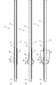
図3に示すように、チューブ本体11の横断面領域において、メインルーメン12や各サブルーメン13,14以外の空いたスペースには、造影ライン15が軸方向に延びるように設けられている。造影ライン15は、放射線(例えばX線)の透視下等で体外からチューブ本体11全体の位置を確認するためのものであり、例えば硫酸バリウム等の放射線を透過させない材料を含むように形成されている。なお、図3中の造影ライン15は、チューブ本体11の基端側にのみ一部を図示したが、実際はチューブ本体11の先端まで延びている。
図2に示すように、チューブ本体11の先端側にて、内側バルーン20の基端側には造影マーカー16が設けられている。造影マーカー16も、放射線(例えばX線)の透視下等で体外から位置を確認することができ、例えば硫酸バリウム等の放射線を透過させない材料を含むように形成される。図2において、造影マーカー16は、内側バルーン20の基端に連なる位置でチューブ本体11の外周面を周回するリング状に設けられている。なお、造影マーカー16は、内側バルーン20の基端側の一部として形成しても良い。
図3に示すように、チューブ本体11には、その軸方向に亘って前記造影マーカー16を起点とする深度マーク17が記されている。深度マーク17は、体腔内に挿入されたチューブ本体11の長さを確認するための目盛りであり、印刷あるいは刻印によって記されている。図3中では深度マーク17を一部のみ図示したが、例えば5~35mmの範囲で目盛りを記すと良い。なお、深度マーク17は、チューブ本体11の外周面に限らず内周面に記しても良く、あるいは周壁の内部に設けるようにしても構わない。
図1に示すように、内側バルーン20は、チューブ本体11の先端側に配置され、チューブ本体11の途中の全周を覆う状態で拡張可能に設けられている。図2に示すように、内側バルーン20の先端側と基端側には、それぞれチューブ本体11の外周面に固着されるフランジ状の接着代21,22があり、両接着代21,22の間の内側には、前記サブルーメン13の開口13aが設けられている。内側バルーン20の材質は、柔軟性があり弾性変形が可能な材質であれば良く、例えばシリコーンゴム等が適している。
内側バルーン20は、サブルーメン13を通じて流体の加圧ないし減圧操作により、チューブ本体11の周りで拡張ないし収縮する。内側バルーン20は、サブルーメン13より流体が導入される加圧操作がなされると、チューブ本体11を中心として前後に若干潰れた球形に拡張し(図2参照)、サブルーメン13より流体が排出される減圧操作がなされると、チューブ本体11の外周面に密着するように収縮する(図3参照)。
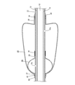
図1に示すように、外側バルーン30は、チューブ本体11の先端側にて、前記内側バルーン20を取り囲む状態で全周方向に拡張可能に設けられている。図2に示すように、外側バルーン30の先端側と基端側にも、それぞれフランジ状の接着代31,32があり、両接着代31,32の間の内側には、前記サブルーメン14の開口14aが設けられている。外側バルーン30の材質も、柔軟性があり弾性変形が可能な材質であれば良く、例えばシリコーンゴム等が適している。
外側バルーン30は、前方となる先端側が前記内側バルーン20の同じく先端側に近接し、かつ、後方となる基端側が前記内側バルーン20の同じく基端側より後方へ延出している。詳しくは、外側バルーン30の先端側の接着代31は、内側バルーン20の先端側の接着代21に重ね合わさる状態で固着されており、各バルーン20,30の先端同士は合致している。一方、外側バルーン30の基端側の接着代32は、内側バルーン20の基端側の接着代21を越えた後方寄りに位置し、当該位置に外嵌させた取付リング18を介してチューブ本体11の外周面に固着されている。
取付リング18は、外側バルーン30の基端側の接着代32の内径が、先端側の接着代31の内径と同じ寸法であるのに対して、内側バルーン20の接着代22に重ね合わせないことで生じる段差を解消するものである。なお、取付リング18を介在させる代わりに、外側バルーン30の基端側の接着代32を厚くして内径を狭めることにより、接着代32をチューブ本体11の外周面に直接固着するようにしても良い。
外側バルーン30は、サブルーメン14を通じて流体の加圧ないし減圧操作により、前記内側バルーン20を取り囲む状態で拡張ないし収縮する。ここで外側バルーン30は、図2に示すように、拡張時に同じく拡張した前記内側バルーン20の先端側に接する先端側よりも、基端側の外径が漸次拡径するテーパー形状に設けられている。図2に示す例では、外側バルーン30は、拡張すると基端側が、同じく拡張した内側バルーン20の先端から半分ほど接しており、これらの接した箇所には流体が入り込み難い。
外側バルーン30は、内側バルーン20の先端から半分ほど接した箇所の終端より後方に向けて、外径が漸次拡径するテーパー形状に膨らむ。外側バルーン30は基端側で最大径となり、この最大径部位から後方の接着代32に向かって縮径する。ここで外側バルーン30の最大径部位より接着代32に至る形状は特に問わないが、図2のように、チューブ本体11の軸心とほぼ直交するよう急に窄まる必要はなく、内側バルーン20と接した箇所の終端から基端側に亘り所定長さのテーパー形状を維持できれば足りる。
外側バルーン30は、サブルーメン14より流体が導入される加圧操作がなされると、前述したテーパー形状に拡張し(図5(c)参照)、サブルーメン14より流体が排出される減圧操作がなされると、内側バルーン20ないしチューブ本体11の外周面に密着するように収縮する(図5(a),(b)参照)。すなわち、外側バルーン30は収縮時に、先端側を含め内側バルーン20を覆う部分は該内側バルーン20に密着し、基端側を含め内側バルーン20を覆わない部分はチューブ本体11の外周面に密着する。
このような外側バルーン30の拡張時の形状は、加減圧しない通常時の元の形状として予め成形しておくことも考えられる。また、外側バルーン30の収縮時の形状が、チューブ本体11の外周面になるべく皺や弛みが生じないよう密着させるために、外側バルーン30を、先端側よりも基端側の肉厚が薄くなるように形成しても良い。外側バルーン30は、その肉厚が薄い部位ほど大きく膨張するため、前述のテーパー形状に合わせて先端側よりも基端側の肉厚が徐々に薄くなるように成形すれば、通常時には先端から基端にかけてほぼ同径の筒状に成形することも可能となる。
また、外側バルーン30の両接着代31,32の前後には、チューブ本体11の外周面との段差をなくすためのコート部33,34が設けられている。前方のコート部33は、内側バルーン20の接着代21に外側バルーン30の接着代31を重ね合わせた厚さ分の段差を解消すべく、当該厚さ分の外径からチューブ本体11の外径に漸次縮径するテーパー形状に設けられている。
後方のコート部34は、取付リング18に外側バルーン30の接着代32を重ね合わせた厚さ分の段差を解消すべく、当該厚さ分の外径からチューブ本体11の外径に漸次縮径するテーパー形状に設けられている。各コート部33,34は、例えばシリコン系のコーティング剤等により成形すると良い。
図1に示すように、チューブ本体11の基端には、メインルーメン12や各サブルーメン13,14が連通接続されたカテーテルヘッド40が設けられている。カテーテルヘッド40は、メインルーメン12と各サブルーメン13,14にそれぞれ連通する三叉のファネル(漏斗)状に形成されている。
カテーテルヘッド40のうち、チューブ本体11と同軸方向に延びる主要部は、メインルーメン12と連通して造影剤等を注入するメインルーメン用の接続コネクタ41となっており、その先端側より分岐する部位は、各サブルーメン13,14と連通してバルーン拡張用の流体を通過させる各サブルーメン用の接続コネクタ42,43となっている。
メインルーメン用の接続コネクタ41の開口部には、図示省略したが開閉可能な栓が備えられている。また、サブルーメン用の接続コネクタ42,43の開口部には、内部に逆止弁が備えられており、各開口部に流体注入用の注射筒(図示せず)を差し込んだ時だけ、各サブルーメン13,14を外部と連通させるように構成されている。なお、カテーテルヘッド40の材質も、例えばシリコーンゴム等が適している。
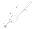
また、図1に示すように、チューブ本体11の最先端には、先端チップ19が設けられることが好ましい。先端チップ19は、チューブ本体11のメインルーメン12と連通する管状に形成されており、体腔内にて狭窄部への挿通性を向上させるためにテーパー加工されている。なお、先端チップ19の材質も、例えばシリコーンゴム等が適している。先端チップ19を設けない場合は、サブルーメン13,14を液状シリコーンゴム等で封止した後、チューブ本体11の先端をテーパー加工しても良い。
次に、本実施の形態に係るバルーンカテーテル10の作用について説明する。
本バルーンカテーテル10は、食道に生じた狭窄部を拡張するものとして、嚥下障害患者の食道入口部の拡張術に最適に用いることができる。先ず、バルーンカテーテル10の先端側を患者の口腔より食道に挿入する。この時、チューブ本体11の先端側にある内側バルーン20と外側バルーン30とは共に収縮させておく。
本バルーンカテーテル10は、食道に生じた狭窄部を拡張するものとして、嚥下障害患者の食道入口部の拡張術に最適に用いることができる。先ず、バルーンカテーテル10の先端側を患者の口腔より食道に挿入する。この時、チューブ本体11の先端側にある内側バルーン20と外側バルーン30とは共に収縮させておく。
すなわち、図5(a)に示すように、内側バルーン20は、チューブ本体11の外周面に密着し、外側バルーン30は、内側バルーン20を覆う部分は、内側バルーン20と共にチューブ本体11の外周面に密着し、内側バルーン20を覆わない延出した部分は、チューブ本体11の外周面に直に密着している。このように各バルーン20,30が収縮した状態では、各バルーン20,30の一部がチューブ本体11に密着せずに大きな弛みや皺を生ずることもなく、スムーズに患者に飲み込ませることができる。
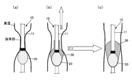
内側バルーン20の基端側には造影マーカー16があるため、放射線(例えばX線)の透視下等で内側バルーン20が食道の狭窄部を通過したかを容易に確認することができる。そして、内側バルーン20が食道の狭窄部を通過した時に、図6(a)に示すように、内側バルーン20を拡張させて狭窄部に固定する。ここで、狭窄部に固定した内側バルーン20が下方(胃側)へずれないように、チューブ本体11を上方(口腔側)へ少し引っ張る。なお、図5(b)に示すように、外側バルーン30のうち、拡張時の内側バルーン20に重なる先端側は、内側バルーン20と共に拡張する。
そして、図6(b)に示すように、チューブ本体11を少し引っ張りつつ、外側バルーン30も拡張させることにより、食道の狭窄部を拡張することができる。図6(c)に示すように、外側バルーン30が拡張すると、その先端側は同じく拡張した内側バルーン20の先端側に接している。そのため、チューブ本体11を上方へ引っ張っていても、外側バルーン30の内容物(流体)は、内側バルーン20の先端側より前方へ移動することはない。
しかも、図5(c)に示すように、外側バルーン30は拡張すると、その先端側よりも基端側の外径が漸次拡径するテーパー形状となる。よって、外側バルーン30は、内側バルーン20と膨らむ範囲が重複しない基端側が体腔内の狭窄部に圧接しても、外側バルーン30の内容物は、外側バルーン30自体の基端側より先端側へいっそう移動し難く、外側バルーン30が変形して狭窄部から位置ずれすることはない。これにより、食道の狭窄部を拡張する時に確実に位置ずれを防止して、容易に施術を行うことができる。
外側バルーン30は、前述したように先端側よりも基端側の肉厚が薄く形成すれば、外側バルーン30を予めテーパー形状に成形しておかなくても、内圧による膨らみ具合の違いによりテーパー形状とすることも可能である。また、基端側を先端側よりも柔軟性や伸縮性の高いシリコーンゴムで成形しても良い。しかも、各バルーン20,30の収縮時における弛みや皺の発生を防ぎ、よりいっそうチューブ本体11に密着させることが可能となる。ここで密着とは、各バルーンの全周において隙間なく密着する状態だけでなく、基端側の外径が大きい分だけ多少のシワが生じても全体的には密着するような状態も含まれる。
また、本バルーンカテーテル10によれば、チューブ本体11は、その軸方向に亘って造影マーカー16を起点とする深度マーク17を備えるため、チューブ本体11を食道の狭窄部に向けて挿入する時に、食道に挿入されたチューブ本体11の長さを容易に確認することができる。さらに、チューブ本体11は、その軸方向に延びる造影ライン15を備えるため、チューブ本体11を食道の狭窄部に向けて挿入する時に、放射線透視下等で食道内におけるチューブ本体11全体の位置を容易に確認することもできる。
以上、本発明の実施の形態を図面によって説明してきたが、具体的な構成は前述した実施の形態に限られるものではなく、本発明の要旨を逸脱しない範囲における変更や追加があっても本発明に含まれる。例えば、チューブ本体11、内側バルーン20、外側バルーン30、カテーテルヘッド40の具体的な形状や相対的な大きさは、図示したものに限定されることはない。
本発明に係るバルーンカテーテルは、嚥下障害患者の食道入口部の拡張術に用いるものに限定されることはなく、他に体腔として、気管や胆管等の消化管や血管等に生じた狭窄部を拡張する治療に用いるもの等、様々な用途のバルーンカテーテルに適用することができる。
10…バルーンカテーテル
11…チューブ本体
12…メインルーメン
13,14…サブルーメン
20…内側バルーン
30…外側バルーン
40…カテーテルヘッド
11…チューブ本体
12…メインルーメン
13,14…サブルーメン
20…内側バルーン
30…外側バルーン
40…カテーテルヘッド
Claims (7)
- 体腔内の狭窄部を拡張する施術に用いるバルーンカテーテル(10)において、
長手方向に延び可撓性のあるチューブ本体(11)を備え、該チューブ本体(11)の途中の外周面に、全周方向に拡張可能な内側バルーン(20)を設けると共に、該内側バルーン(20)を取り囲む状態で全周方向に拡張可能な外側バルーン(30)を設け、
前記外側バルーン(30)は、前記チューブ本体(11)の進入方向の前方となる先端側が前記内側バルーン(20)の同じく先端側に近接し、かつ、前記チューブ本体(11)の進入方向の後方となる基端側が前記内側バルーン(20)の同じく基端側より後方へ延出しており、
前記外側バルーン(30)は、拡張時に同じく拡張した前記内側バルーン(20)の先端側に接する先端側よりも基端側の外径が漸次拡径するテーパー形状に設けられたことを特徴とするバルーンカテーテル(10)。 - 前記外側バルーン(30)は、先端側よりも基端側の肉厚が薄く形成されたことを特徴とする請求項1に記載のバルーンカテーテル(10)。
- 前記内側バルーン(20)は収縮時に、前記チューブ本体(11)の外周面に密着し、
前記外側バルーン(30)は収縮時に、先端側を含め前記内側バルーン(20)を覆う部分は該内側バルーン(20)に密着し、基端側を含め前記内側バルーン(20)を覆わない部分は前記チューブ本体(11)の外周面に密着するように設けられたことを特徴とする請求項1または2に記載のバルーンカテーテル(10)。 - 前記内側バルーン(20)の基端側に造影マーカー(16)を備えたことを特徴とする請求項1,2または3に記載のバルーンカテーテル(10)。
- 前記チューブ本体(11)は、その軸方向に亘って前記造影マーカー(16)を起点とする深度マーク(17)を備えたことを特徴とする請求項1,2,3または4に記載のバルーンカテーテル(10)。
- 前記チューブ本体(11)は、その軸方向に延びる造影ライン(15)を備えたことを特徴とする請求項1,2,3,4または5に記載のバルーンカテーテル(10)。
- 前記体腔は食道であり、嚥下障害患者の食道入口部の拡張術に用いられるものであることを特徴とする請求項1,2,3,4,5または6に記載のバルーンカテーテル(10)。
Applications Claiming Priority (2)
| Application Number | Priority Date | Filing Date | Title |
|---|---|---|---|
| JP2017227619A JP6708615B2 (ja) | 2017-11-28 | 2017-11-28 | バルーンカテーテル |
| JP2017-227619 | 2017-11-28 |
Publications (1)
| Publication Number | Publication Date |
|---|---|
| WO2019107308A1 true WO2019107308A1 (ja) | 2019-06-06 |
Family
ID=66664919
Family Applications (1)
| Application Number | Title | Priority Date | Filing Date |
|---|---|---|---|
| PCT/JP2018/043378 WO2019107308A1 (ja) | 2017-11-28 | 2018-11-26 | バルーンカテーテル |
Country Status (2)
| Country | Link |
|---|---|
| JP (1) | JP6708615B2 (ja) |
| WO (1) | WO2019107308A1 (ja) |
Families Citing this family (2)
| Publication number | Priority date | Publication date | Assignee | Title |
|---|---|---|---|---|
| CN112843436A (zh) * | 2020-02-16 | 2021-05-28 | 东莞天天向上医疗科技有限公司 | 一种体内肺膜氧合多功能球囊扩张导管及使用方法 |
| KR102337461B1 (ko) * | 2021-01-18 | 2021-12-13 | 충남대학교병원 | 팽창식 고정구조를 가지는 배액관 |
Citations (6)
| Publication number | Priority date | Publication date | Assignee | Title |
|---|---|---|---|---|
| US5536252A (en) * | 1994-10-28 | 1996-07-16 | Intelliwire, Inc. | Angioplasty catheter with multiple coaxial balloons |
| JP2002520095A (ja) * | 1998-07-09 | 2002-07-09 | ボストン サイエンティフィック リミテッド | バルーンの末端部でバルーンが膨張するバルーンカテーテル、およびステント配送システム |
| US20050209674A1 (en) * | 2003-09-05 | 2005-09-22 | Kutscher Tuvia D | Balloon assembly (V) |
| WO2012032881A1 (ja) * | 2010-09-06 | 2012-03-15 | テルモ株式会社 | 医療用長尺体 |
| JP2014528285A (ja) * | 2011-09-30 | 2014-10-27 | メモリアル スローン−ケタリング キャンサー センター | 体腔治療用アプリケータ装置およびその使用方法 |
| JP2016059626A (ja) * | 2014-09-18 | 2016-04-25 | テルモ株式会社 | バルーンカテーテル |
-
2017
- 2017-11-28 JP JP2017227619A patent/JP6708615B2/ja active Active
-
2018
- 2018-11-26 WO PCT/JP2018/043378 patent/WO2019107308A1/ja active Application Filing
Patent Citations (6)
| Publication number | Priority date | Publication date | Assignee | Title |
|---|---|---|---|---|
| US5536252A (en) * | 1994-10-28 | 1996-07-16 | Intelliwire, Inc. | Angioplasty catheter with multiple coaxial balloons |
| JP2002520095A (ja) * | 1998-07-09 | 2002-07-09 | ボストン サイエンティフィック リミテッド | バルーンの末端部でバルーンが膨張するバルーンカテーテル、およびステント配送システム |
| US20050209674A1 (en) * | 2003-09-05 | 2005-09-22 | Kutscher Tuvia D | Balloon assembly (V) |
| WO2012032881A1 (ja) * | 2010-09-06 | 2012-03-15 | テルモ株式会社 | 医療用長尺体 |
| JP2014528285A (ja) * | 2011-09-30 | 2014-10-27 | メモリアル スローン−ケタリング キャンサー センター | 体腔治療用アプリケータ装置およびその使用方法 |
| JP2016059626A (ja) * | 2014-09-18 | 2016-04-25 | テルモ株式会社 | バルーンカテーテル |
Also Published As
| Publication number | Publication date |
|---|---|
| JP2019093071A (ja) | 2019-06-20 |
| JP6708615B2 (ja) | 2020-06-10 |
Similar Documents
| Publication | Publication Date | Title |
|---|---|---|
| JP4399544B2 (ja) | 改良されたバルーン配置をもつ胃のバルーンカテーテル | |
| US6958035B2 (en) | Medical device sheath apparatus and method of making and using same | |
| JP4772446B2 (ja) | 内視鏡挿入補助具及び内視鏡装置 | |
| AU2005203844B2 (en) | Pressure-propelled system for body lumen | |
| JP2005522278A (ja) | 内視鏡用の拡張バルーン | |
| US20090287050A1 (en) | Eccentric Dilation Balloons for Use of Endoscopes | |
| US10561828B2 (en) | Treatment tool for endoscope | |
| JP2005508710A (ja) | 円筒形の中空ヘッドを備えた自動推進式の管腔内器具およびその使用方法 | |
| US20100137783A1 (en) | Gastric tube and a method for introducing a gastric tube | |
| US20150209239A1 (en) | Nasogastric tube | |
| CN104857617A (zh) | 球囊导管 | |
| US20200352550A1 (en) | Therapeutic substance delivery device and therapeutic substance delivery kit | |
| WO2019107308A1 (ja) | バルーンカテーテル | |
| JP2012055602A (ja) | カテーテル | |
| US11395677B2 (en) | Devices, systems, and methods for use with suction within a mammalian body | |
| WO2013122056A1 (ja) | 拡張カテーテル | |
| RU2669052C1 (ru) | Катетер для проведения электрофореза и введения лекарственных средств в барабанную полость | |
| JP4499479B2 (ja) | 内視鏡用オーバーチューブおよび小腸内視鏡システム | |
| AU2007202075B2 (en) | Medical instrument having a catheter and method for using a catheter | |
| JP7364482B2 (ja) | バルーンカテーテル | |
| JP4705715B2 (ja) | バルーンカテーテル | |
| WO2021059943A1 (ja) | バルーンカテーテル | |
| JP2021049256A (ja) | バルーンカテーテル | |
| CN209967370U (zh) | 扩张导引器 | |
| US20190365208A1 (en) | Catheter and tube introducer |
Legal Events
| Date | Code | Title | Description |
|---|---|---|---|
| 121 | Ep: the epo has been informed by wipo that ep was designated in this application |
Ref document number: 18884378 Country of ref document: EP Kind code of ref document: A1 |
|
| NENP | Non-entry into the national phase |
Ref country code: DE |
|
| 122 | Ep: pct application non-entry in european phase |
Ref document number: 18884378 Country of ref document: EP Kind code of ref document: A1 |