WO2019107308A1 - バルーンカテーテル - Google Patents
バルーンカテーテル Download PDFInfo
- Publication number
- WO2019107308A1 WO2019107308A1 PCT/JP2018/043378 JP2018043378W WO2019107308A1 WO 2019107308 A1 WO2019107308 A1 WO 2019107308A1 JP 2018043378 W JP2018043378 W JP 2018043378W WO 2019107308 A1 WO2019107308 A1 WO 2019107308A1
- Authority
- WO
- WIPO (PCT)
- Prior art keywords
- balloon
- end side
- inner balloon
- catheter
- distal end
- Prior art date
- Legal status (The legal status is an assumption and is not a legal conclusion. Google has not performed a legal analysis and makes no representation as to the accuracy of the status listed.)
- Ceased
Links
Images


Classifications
-
- A—HUMAN NECESSITIES
- A61—MEDICAL OR VETERINARY SCIENCE; HYGIENE
- A61M—DEVICES FOR INTRODUCING MEDIA INTO, OR ONTO, THE BODY; DEVICES FOR TRANSDUCING BODY MEDIA OR FOR TAKING MEDIA FROM THE BODY; DEVICES FOR PRODUCING OR ENDING SLEEP OR STUPOR
- A61M25/00—Catheters; Hollow probes
- A61M25/10—Balloon catheters
Definitions
- the present invention relates to a balloon catheter used in a treatment for dilating a stenosis in a body cavity.
- a balloon catheter is widely used for treatment for dilation of a constricted part generated in a body cavity.
- the balloon catheter has a double balloon structure and is configured for fixation and expansion.
- the balloon catheter 1 for esophagus dilation is provided with an inner balloon 3 which is spherically expanded on the outer peripheral surface of the tube main body 2 for fixation, and is expanded into a long rod shape back and forth so as to surround the outside.
- An outer balloon 4 was provided for dilation.
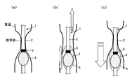
- the catheter 1 In the swallowing training procedure for patients with dysphagia using the balloon catheter 1, first, as shown in FIG. 7A, the catheter 1 is inserted from the oral cavity into the esophagus under fluoroscopy. At this time, since the imaging ring 5 is provided on the catheter 1, it can be confirmed whether the inner balloon 3 has passed through the narrow portion of the esophagus. Then, when the inner balloon 3 passes through the narrowing portion of the esophagus, the inner balloon 3 is expanded and fixed to the narrowing portion.
- the outer balloon 4 is expanded while pulling the tube main body 2 slightly upward (oral side) so that the inner balloon 3 fixed to the narrowed portion does not shift downward (stomach side). .
- the outer balloon 4 is wedge-shaped and its expansion causes the entire balloon to spread and provide pressure stimulation to the stenosis.
- the content (air) of the outer balloon 4 is shifted downward, and the position of the entire outer balloon 4 is displaced. There was a problem.
- patent document 1 As a prior art which can solve the problem mentioned above, what was disclosed by patent document 1, for example is known. That is, while providing a plurality of inner balloons axially spaced from each other on the outer peripheral surface of the tube main body, and covering each inner balloon, and providing an outer balloon portion which can be easily expanded from each inner balloon It is. According to such a balloon catheter, the narrowed portion fits in the valley portion of both inner balloons, and it is possible to prevent positional deviation even if the outer balloon is expanded.
- the present invention has been made focusing on the problems of the prior art as described above, and the number of balloons is only two, the inner side and the outer side, and the simple configuration causes no cost increase. It is another object of the present invention to provide a balloon catheter which can be easily operated with easy operation and requires less labor and time and reliably prevents displacement when expanding a constriction in a body cavity.
- a longitudinally extending and flexible tube body is provided, and the circumferential surface on the way of the tube body is provided with a circumferentially expandable inner balloon and is circumferentially expandable in a state surrounding the inner balloon
- an outer balloon The distal end side of the outer balloon, which is forward in the advancing direction of the tube main body, is close to the same distal end side of the inner balloon, and the proximal end which is backward of the advancing direction of the tube main body is the same proximal end of the inner balloon.
- the balloon catheter is characterized in that the outer balloon is provided in a tapered shape in which the outer diameter on the proximal side of the distal end side in contact with the distal end side of the inner balloon expanded similarly is gradually enlarged.
- the inner balloon is in close contact with the outer peripheral surface of the tube body during contraction;
- the portion covering the inner balloon including the distal end is in intimate contact with the inner balloon, and the portion not covering the inner balloon including the proximal end is in intimate contact with the outer peripheral surface of the tube body.
- the body cavity is an esophagus, which is used for dilation of the esophagus entrance of patients with dysphagia. [1], [2], [3], [4], [5] ] Or the balloon catheter as described in [6].
- the tube body is provided with two balloons, an inner balloon and an outer balloon surrounding the inner balloon.
- the distal end of the outer balloon is close to the distal end of the inner balloon, and the proximal end extends rearward from the proximal end of the inner balloon.
- the distal end of the outer balloon overlaps with the distal end of the inner balloon, but the proximal end of the outer balloon does not overlap with the inner balloon.
- the outer balloon When the outer balloon is expanded, its distal end is in contact with the distal end of the similarly expanded inner balloon. Therefore, the contents (fluid) of the outer balloon do not move forward from the tip side of the inner balloon.
- the outer diameter of the proximal end side gradually becomes larger than that of the distal end side in a tapered shape. Therefore, even if the proximal end of the outer balloon, which does not overlap with the inner balloon, is pressed against the narrow portion in the body cavity, the contents of the outer balloon are less likely to move distally than the proximal end of the outer balloon itself.
- the outer balloon is not deformed and misaligned from the stenosis.
- the outer balloon is formed to have a thinner wall thickness on the proximal side than on the distal side.
- the outer balloon is more likely to expand proximally than distally when expanding to fill the fluid. Therefore, even if the outer balloon is not previously formed into the tapered shape, it is also possible to make it into a tapered shape according to the difference in the degree of expansion due to the internal pressure.
- the inner balloon adheres to the outer peripheral surface of the tube main body at the time of contraction. Also, when the outer balloon is contracted, the portion covering the inner balloon including the distal end is in intimate contact with the inner balloon, and the portion not covering the inner balloon including the proximal end is in intimate contact with the outer peripheral surface of the tube body.
- the term "adhesion" includes not only a state in which there is no gap in the entire circumference of each balloon, but also a state in which even if some wrinkles occur due to the larger outer diameter of the proximal end .
- the imaging marker is provided on the proximal side of the inner balloon, when the tube main body is inserted toward the narrowed portion in the body cavity, the inner balloon The position can be easily confirmed.
- the tube main body is provided with the depth mark starting from the contrast marker in the axial direction, when the tube main body is inserted toward the stenosis portion in the body cavity, The length of the tube body inserted into the body cavity can be easily confirmed.
- the tube main body is provided with the contrast line extending in the axial direction, when inserting the tube main body toward the narrowed portion in the body cavity, the body cavity under radioscopy etc. The position of the entire tube body in the inside can be easily confirmed.
- the above-mentioned balloon catheter can be used optimally for dilation of the esophagus entrance of patients with dysphagia, for example, as described in the above-mentioned [7], as an apparatus for dilating a constriction in the esophagus.
- the simple configuration does not lead to an increase in cost, and the operation is simple, and it does not take time and effort. It can be prevented and the treatment can be performed easily.
- the balloon catheter 10 which concerns on this Embodiment is a medical instrument used for the treatment which dilates the stenosis part in a body cavity.
- the balloon catheter 10 will be described as an example of using the balloon catheter 10 for dilation of the esophagus entrance of a patient with dysphagia, as an apparatus for dilating a stenosis in the esophagus.
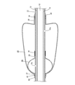
- the balloon catheter 10 is provided with a longitudinally extending flexible tube body 11 and an inner circumferential balloon 20 is provided on the outer circumferential surface of the tube body 11 in the circumferential direction. And a circumferentially expandable outer balloon 30 is provided so as to surround the inner balloon 20.
- Each balloon 20, 30 is disposed on the front end side (left side in FIG. 1) which is the front side in the approach direction of the tube main body 11, and is proximal end side (the right side in FIG.
- the catheter head 40 is disposed on the
- the tube body 11 is an elongated tubular member which can be freely curved.
- the material of the tube main body 11 is, for example, a flexible synthetic resin such as silicone rubber or soft polyvinyl chloride.
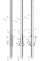
- the main lumen 12 of the main conduit and the two sub lumens 13 and 14 for supplying fluid for expanding the balloons 20 and 30 are axially separated as independent conduits. It is formed to extend.
- the main lumen 12 is for introducing a chemical solution such as a contrast agent or a nutrient or for aspirating saliva, and is formed as a conduit extending around the axial center of the tube main body 11.
- the tip of the main lumen 12 is open to the outside from the tip of the tube body 11.
- the proximal end of the main lumen 12 communicates with the inside of a catheter head 40 described later.
- One sub-lumen 13 is for passing a fluid (for example, air, sterile distilled water or the like) for expanding the inner balloon 20 described later, and a thin tube extending in the axial direction at a position eccentric from the axial center of the tube main body 11 It is formed as a road.
- the tip end of the sub-lumen 13 is sealed, and the tip end side is opened from the outer peripheral surface of the tube main body 11 and communicates with the inside of the inner balloon 20 (see FIG. 2).
- the proximal end of the sub lumen 13 communicates with the inside of a catheter head 40 described later.
- the other sub-lumen 14 is for passing a fluid (for example, air, sterile distilled water, etc.) for expanding the outer balloon 30 described later, and an axis on the opposite side of the sub-lumen 13 with the main lumen 12 in between. It is formed as an axially extending thin channel at a position off-center from the center.
- the tip of the sub-lumen 14 is also sealed, and the tip end side is opened from the outer peripheral surface of the tube body 11 and is in communication with the inside of the outer balloon 30 (see FIG. 2).
- the proximal end of the sub-lumen 14 communicates with the inside of a catheter head 40 described later.
- a contrast line 15 is provided so as to extend in the axial direction in a vacant space other than the main lumen 12 and the respective sub lumens 13 and 14.
- the contrast line 15 is for confirming the position of the entire tube body 11 from outside the body under the perspective of radiation (for example, X-ray), and is formed to include a material that does not transmit radiation such as barium sulfate, for example. There is. Although a part of the contrast line 15 in FIG. 3 is shown only on the proximal end side of the tube main body 11, it actually extends to the tip of the tube main body 11.
- a contrast marker 16 is provided on the proximal end side of the inner balloon 20 on the distal end side of the tube main body 11.
- the contrast marker 16 is also formed so as to be able to confirm its position from outside the body under the perspective of radiation (for example, X-rays) and includes a material which does not transmit radiation, such as barium sulfate.
- the contrast marker 16 is provided in a ring shape that goes around the outer peripheral surface of the tube main body 11 at a position connected to the proximal end of the inner balloon 20.
- the contrast marker 16 may be formed as part of the proximal side of the inner balloon 20.
- a depth mark 17 starting from the contrast marker 16 is marked on the tube body 11 in the axial direction.
- the depth mark 17 is a scale for confirming the length of the tube body 11 inserted into the body cavity, and is marked by printing or engraving. Although only a part of the depth mark 17 is shown in FIG. 3, it is preferable to draw a scale in the range of 5 to 35 mm, for example.
- the depth mark 17 may be written not only on the outer peripheral surface of the tube main body 11 but also on the inner peripheral surface, or may be provided inside the peripheral wall.
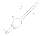
- the inner balloon 20 is disposed on the distal end side of the tube main body 11 and is expandable in a state of covering the entire circumference of the tube main body 11 in the middle.
- flange-like adhesion margins 21 and 22 fixed to the outer peripheral surface of the tube main body 11 are provided on the distal end side and the proximal end side of the inner balloon 20, respectively.
- the opening 13a of the sub-lumen 13 is provided on the inner side of the sub-lumen.
- the material of the inner balloon 20 may be a flexible and elastically deformable material, and, for example, silicone rubber is suitable.
- the inner balloon 20 expands or contracts around the tube body 11 by pressurizing or depressurizing the fluid through the sub-lumen 13.
- the inner balloon 20 is expanded into a spherical shape which is slightly crushed back and forth centering on the tube body 11 when the fluid is introduced from the sub-lumen 13 (see FIG. 2), and the fluid is discharged from the sub-lumen 13 When the reduced pressure operation is performed, it contracts so as to be in close contact with the outer peripheral surface of the tube body 11 (see FIG. 3).
- the outer balloon 30 is provided on the distal end side of the tube main body 11 so as to be expandable in the circumferential direction so as to surround the inner balloon 20.
- flange-shaped adhesion margins 31 and 32 are also provided on the distal end side and the proximal end side of the outer balloon 30, respectively.
- An opening 14a is provided.
- the material of the outer balloon 30 may also be a flexible and elastically deformable material, and, for example, silicone rubber is suitable.
- the distal end side of the outer balloon 30 is close to the same distal end side of the inner balloon 20 and the proximal end side of the outer balloon 30 extends rearward from the proximal end side of the inner balloon 20.
- the adhesion margin 31 on the distal end side of the outer balloon 30 is fixed in a state of being superimposed on the adhesion margin 21 on the distal end side of the inner balloon 20, and the tips of the balloons 20 and 30 coincide with each other.
- the adhesion margin 32 on the proximal end side of the outer balloon 30 is positioned on the rear side beyond the adhesion margin 21 on the proximal end side of the inner balloon 20, and the tube body is fitted via the mounting ring 18 fitted outside in that position. It is fixed to the outer peripheral surface of 11.
- the attachment ring 18 does not overlap the adhesion margin 22 of the inner balloon 20 while the inner diameter of the adhesion margin 32 on the proximal side of the outer balloon 30 has the same dimension as the inner diameter of the adhesion margin 31 on the distal side.
- the adhesion margin 32 may be directly adhered to the outer peripheral surface of the tube main body 11 by thickening the adhesion margin 32 on the base end side of the outer balloon 30 and narrowing the inner diameter. good.
- the outer balloon 30 is expanded or contracted around the inner balloon 20 by pressurizing or depressurizing the fluid through the sub-lumen 14.
- the outer balloon 30 is provided in a tapered shape in which the outer diameter on the proximal end side gradually increases in diameter rather than the distal end side in contact with the distal end side of the inner balloon 20 similarly expanded during expansion. There is.
- the proximal end side is in contact with the distal end of the expanded inner balloon 20 by about half, and the fluid is difficult to enter into these contact points.
- the outer balloon 30 is expanded in a tapered shape in which the outer diameter gradually expands toward the rear from the end of the portion where the outer balloon 30 is in contact with the distal end of the inner balloon 20.
- the outer balloon 30 has the largest diameter on the proximal end side, and the diameter is reduced from the largest diameter portion toward the adhesive margin 32 at the rear.
- the shape from the largest diameter portion of the outer balloon 30 to the adhesion margin 32 is not particularly limited. However, as shown in FIG. It is sufficient if the tapered shape having a predetermined length can be maintained from the terminal end to the proximal end side of the contact portion.
- the outer balloon 30 is expanded into the above-described tapered shape (see FIG. 5C) when a pressure operation is performed in which the fluid is introduced from the sub-lumen 14 (see FIG. 5C), and a pressure reducing operation in which the fluid is discharged from the sub-lumen 14 is
- the inner balloon 20 and the outer peripheral surface of the tube main body 11 contract so as to be in intimate contact (see FIGS. 5 (a) and 5 (b)). That is, when the outer balloon 30 is contracted, the portion covering the inner balloon 20 including the distal end is in close contact with the inner balloon 20 and the portion not covering the inner balloon 20 including the proximal end is in contact with the outer peripheral surface of the tube main body 11 .
- such an expanded shape of the outer balloon 30 is formed in advance as an original shape at the normal time when the pressure is not reduced. Further, the thickness of the outer balloon 30 on the proximal end side is thinner than that on the distal end side in order for the outer balloon 30 to be in close contact with the outer peripheral surface of the tube main body 11 so that wrinkles and slack do not occur as much as possible. It may be formed as follows. Since the outer balloon 30 is expanded more as the thickness is thinner, if it is formed so that the thickness on the base end side gradually becomes smaller than the tip end side in accordance with the above-mentioned taper shape, It is also possible to form a cylinder of substantially the same diameter across the end.
- coat portions 33 and 34 for eliminating a step with the outer peripheral surface of the tube main body 11 are provided on the front and back of both adhesion margins 31 and 32 of the outer balloon 30.
- the front coat portion 33 has the outer diameter of the tube main body 11 from the outer diameter of the thickness in order to eliminate the step by the thickness of the adhesion margin 31 of the outer balloon 30 superimposed on the adhesion margin 21 of the inner balloon 20. It is provided in a tapered shape that gradually reduces its diameter.
- the rear coat portion 34 gradually reduces the outer diameter of the thickness to the outer diameter of the tube main body 11 in order to eliminate the difference in thickness of the bonding margin 32 of the outer balloon 30 on the mounting ring 18.
- the coated portions 33 and 34 may be formed of, for example, a silicon-based coating agent.
- a catheter head 40 in which the main lumen 12 and the sub lumens 13 and 14 are connected in communication is provided.
- the catheter head 40 is formed in the shape of a three-forked funnel communicating with the main lumen 12 and the sub lumens 13 and 14, respectively.
- the main part of the catheter head 40 which extends in the coaxial direction with the tube main body 11, is connected to the main lumen 12 to form a connection connector 41 for the main lumen for injecting a contrast medium or the like.
- a connector 42, 43 for each sublumen in communication with each sublumen 13, 14 to pass fluid for balloon expansion.
- the opening of the main lumen connection connector 41 is provided with a plug that can be opened and closed although it is not shown.
- the openings of the sub-lumen connection connectors 42 and 43 are provided with check valves in the inside, and only when a syringe barrel (not shown) for fluid injection is inserted into each opening.
- the sub lumens 13 and 14 are configured to communicate with the outside.
- the material of the catheter head 40 is also preferably silicone rubber, for example.
- a tip 19 be provided at the tip of the tube main body 11.
- the distal end tip 19 is formed in a tubular shape communicating with the main lumen 12 of the tube main body 11, and is tapered in order to improve the penetration into the narrowed portion in the body cavity.
- the material of the tip 19 is also preferably silicone rubber, for example.
- the present balloon catheter 10 can be optimally used for dilation of the esophagus entrance of patients with dysphagia, as a means for dilating a stenosis in the esophagus.
- the distal end side of the balloon catheter 10 is inserted into the esophagus from the patient's oral cavity.
- the inner balloon 20 and the outer balloon 30 on the distal end side of the tube main body 11 are both contracted.
- the inner balloon 20 is in close contact with the outer peripheral surface of the tube body 11, and the outer balloon 30 covers the inner balloon 20 along with the inner balloon 20.
- the extended portion which does not cover the inner balloon 20 is in close contact with the outer peripheral surface of the tube main body 11 directly. In this manner, when the balloons 20 and 30 are in a contracted state, a part of each balloon 20 and 30 does not contact the tube main body 11 and can be smoothly swallowed by the patient without causing a large slack and wrinkles. .
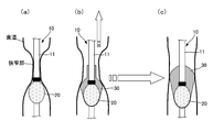
- the contrast marker 16 is provided on the proximal side of the inner balloon 20, it can be easily confirmed whether the inner balloon 20 has passed through a narrowing portion of the esophagus by fluoroscopy of radiation (for example, X-ray). Then, when the inner balloon 20 passes through the narrowing portion of the esophagus, as shown in FIG. 6A, the inner balloon 20 is expanded and fixed to the narrowing portion. Here, the tube main body 11 is pulled a little upward (oral side) so that the inner balloon 20 fixed to the narrowed portion does not shift downward (stomach side). As shown in FIG. 5 (b), the distal end side of the outer balloon 30 overlapping the inner balloon 20 at the time of expansion is expanded together with the inner balloon 20.
- fluoroscopy of radiation for example, X-ray
- the narrow portion of the esophagus can be expanded by expanding the outer balloon 30 while pulling the tube body 11 a little.
- the distal end side is in contact with the distal end side of the similarly expanded inner balloon 20. Therefore, even if the tube body 11 is pulled upward, the content (fluid) of the outer balloon 30 does not move forward from the distal end side of the inner balloon 20.
- the outer balloon 30 when the outer balloon 30 is expanded, it has a tapered shape in which the outer diameter on the proximal end side gradually expands from the distal end side. Therefore, even if the proximal side of the outer balloon 30, which does not overlap with the inner balloon 20, is in pressure contact with the narrow portion in the body cavity, the contents of the outer balloon 30 extend from the proximal side to the distal side of the outer balloon 30 itself. It is even more difficult to move and the outer balloon 30 is not deformed and misaligned from the stenosis. Thereby, when dilating the narrowing part of esophagus, position shift can be prevented reliably and treatment can be performed easily.
- the outer balloon 30 may have a tapered shape due to the difference in the degree of swelling due to the internal pressure without forming the outer balloon 30 in advance. It is also possible. Further, the proximal end side may be formed of silicone rubber having higher flexibility and elasticity than the distal end side. In addition, it is possible to prevent the occurrence of slack and wrinkles at the time of contraction of the respective balloons 20 and 30, and to make it more in close contact with the tube main body 11.
- the term "adhesion" includes not only a state in which there is no gap in the entire circumference of each balloon, but also a state in which even if some wrinkles occur due to the larger outer diameter of the proximal end .
- the tube main body 11 is provided with the depth mark 17 starting from the imaging marker 16 in the axial direction, when inserting the tube main body 11 toward the stricture of the esophagus, The length of the tube body 11 inserted into the esophagus can be easily confirmed. Furthermore, since the tube body 11 is provided with the imaging line 15 extending in the axial direction, when the tube body 11 is inserted toward the narrowing portion of the esophagus, the entire position of the tube body 11 in the esophagus is facilitated under radioscopy etc. You can also check
- the balloon catheter according to the present invention is not limited to the one used for dilation of the esophagus entrance of patients with dysphagia, and it may be used as a body cavity in addition to a constriction in a digestive tract such as trachea or bile duct or blood vessel It can be applied to balloon catheters for various applications, such as those used for dilation therapy.
Landscapes
- Health & Medical Sciences (AREA)
- Life Sciences & Earth Sciences (AREA)
- Heart & Thoracic Surgery (AREA)
- Engineering & Computer Science (AREA)
- Biophysics (AREA)
- Pulmonology (AREA)
- Child & Adolescent Psychology (AREA)
- Anesthesiology (AREA)
- Biomedical Technology (AREA)
- Hematology (AREA)
- Animal Behavior & Ethology (AREA)
- General Health & Medical Sciences (AREA)
- Public Health (AREA)
- Veterinary Medicine (AREA)
- Media Introduction/Drainage Providing Device (AREA)
Applications Claiming Priority (2)
| Application Number | Priority Date | Filing Date | Title |
|---|---|---|---|
| JP2017227619A JP6708615B2 (ja) | 2017-11-28 | 2017-11-28 | バルーンカテーテル |
| JP2017-227619 | 2017-11-28 |
Publications (1)
| Publication Number | Publication Date |
|---|---|
| WO2019107308A1 true WO2019107308A1 (ja) | 2019-06-06 |
Family
ID=66664919
Family Applications (1)
| Application Number | Title | Priority Date | Filing Date |
|---|---|---|---|
| PCT/JP2018/043378 Ceased WO2019107308A1 (ja) | 2017-11-28 | 2018-11-26 | バルーンカテーテル |
Country Status (2)
| Country | Link |
|---|---|
| JP (1) | JP6708615B2 (enExample) |
| WO (1) | WO2019107308A1 (enExample) |
Cited By (1)
| Publication number | Priority date | Publication date | Assignee | Title |
|---|---|---|---|---|
| CN116212226A (zh) * | 2021-12-03 | 2023-06-06 | 李大庆 | 泵血装置体内球囊泵 |
Families Citing this family (2)
| Publication number | Priority date | Publication date | Assignee | Title |
|---|---|---|---|---|
| CN112843436A (zh) * | 2020-02-16 | 2021-05-28 | 东莞天天向上医疗科技有限公司 | 一种体内肺膜氧合多功能球囊扩张导管及使用方法 |
| KR102337461B1 (ko) * | 2021-01-18 | 2021-12-13 | 충남대학교병원 | 팽창식 고정구조를 가지는 배액관 |
Citations (6)
| Publication number | Priority date | Publication date | Assignee | Title |
|---|---|---|---|---|
| US5536252A (en) * | 1994-10-28 | 1996-07-16 | Intelliwire, Inc. | Angioplasty catheter with multiple coaxial balloons |
| JP2002520095A (ja) * | 1998-07-09 | 2002-07-09 | ボストン サイエンティフィック リミテッド | バルーンの末端部でバルーンが膨張するバルーンカテーテル、およびステント配送システム |
| US20050209674A1 (en) * | 2003-09-05 | 2005-09-22 | Kutscher Tuvia D | Balloon assembly (V) |
| WO2012032881A1 (ja) * | 2010-09-06 | 2012-03-15 | テルモ株式会社 | 医療用長尺体 |
| JP2014528285A (ja) * | 2011-09-30 | 2014-10-27 | メモリアル スローン−ケタリング キャンサー センター | 体腔治療用アプリケータ装置およびその使用方法 |
| JP2016059626A (ja) * | 2014-09-18 | 2016-04-25 | テルモ株式会社 | バルーンカテーテル |
-
2017
- 2017-11-28 JP JP2017227619A patent/JP6708615B2/ja active Active
-
2018
- 2018-11-26 WO PCT/JP2018/043378 patent/WO2019107308A1/ja not_active Ceased
Patent Citations (6)
| Publication number | Priority date | Publication date | Assignee | Title |
|---|---|---|---|---|
| US5536252A (en) * | 1994-10-28 | 1996-07-16 | Intelliwire, Inc. | Angioplasty catheter with multiple coaxial balloons |
| JP2002520095A (ja) * | 1998-07-09 | 2002-07-09 | ボストン サイエンティフィック リミテッド | バルーンの末端部でバルーンが膨張するバルーンカテーテル、およびステント配送システム |
| US20050209674A1 (en) * | 2003-09-05 | 2005-09-22 | Kutscher Tuvia D | Balloon assembly (V) |
| WO2012032881A1 (ja) * | 2010-09-06 | 2012-03-15 | テルモ株式会社 | 医療用長尺体 |
| JP2014528285A (ja) * | 2011-09-30 | 2014-10-27 | メモリアル スローン−ケタリング キャンサー センター | 体腔治療用アプリケータ装置およびその使用方法 |
| JP2016059626A (ja) * | 2014-09-18 | 2016-04-25 | テルモ株式会社 | バルーンカテーテル |
Cited By (1)
| Publication number | Priority date | Publication date | Assignee | Title |
|---|---|---|---|---|
| CN116212226A (zh) * | 2021-12-03 | 2023-06-06 | 李大庆 | 泵血装置体内球囊泵 |
Also Published As
| Publication number | Publication date |
|---|---|
| JP2019093071A (ja) | 2019-06-20 |
| JP6708615B2 (ja) | 2020-06-10 |
Similar Documents
| Publication | Publication Date | Title |
|---|---|---|
| JP7364482B2 (ja) | バルーンカテーテル | |
| AU2005203844B2 (en) | Pressure-propelled system for body lumen | |
| US6958035B2 (en) | Medical device sheath apparatus and method of making and using same | |
| JP4772446B2 (ja) | 内視鏡挿入補助具及び内視鏡装置 | |
| US10561828B2 (en) | Treatment tool for endoscope | |
| JP2005522278A (ja) | 内視鏡用の拡張バルーン | |
| US20090287050A1 (en) | Eccentric Dilation Balloons for Use of Endoscopes | |
| US20150209239A1 (en) | Nasogastric tube | |
| US20100137783A1 (en) | Gastric tube and a method for introducing a gastric tube | |
| US20220354538A1 (en) | Devices, systems, and methods for use with suction within a mammalian body | |
| WO2019107308A1 (ja) | バルーンカテーテル | |
| JP2010004915A (ja) | 嚥下障害治療用バルーンカテーテル | |
| US20190365208A1 (en) | Catheter and tube introducer | |
| AU2007202075B2 (en) | Medical instrument having a catheter and method for using a catheter | |
| WO2013122056A1 (ja) | 拡張カテーテル | |
| RU2669052C1 (ru) | Катетер для проведения электрофореза и введения лекарственных средств в барабанную полость | |
| JP4705715B2 (ja) | バルーンカテーテル | |
| WO2021059943A1 (ja) | バルーンカテーテル | |
| JP2021029551A (ja) | カテーテル | |
| CN220443019U (zh) | 一种内镜下使用的肠梗阻导管 | |
| CA3106138C (en) | Catheter and tube introducer | |
| JP2021049256A (ja) | バルーンカテーテル | |
| JP2968266B1 (ja) | 医療用カテーテル | |
| JP2018064866A (ja) | カテーテル押込み補助具 | |
| JP2023512049A (ja) | 器具付属品のための装置、システムおよび方法 |
Legal Events
| Date | Code | Title | Description |
|---|---|---|---|
| 121 | Ep: the epo has been informed by wipo that ep was designated in this application |
Ref document number: 18884378 Country of ref document: EP Kind code of ref document: A1 |
|
| NENP | Non-entry into the national phase |
Ref country code: DE |
|
| 122 | Ep: pct application non-entry in european phase |
Ref document number: 18884378 Country of ref document: EP Kind code of ref document: A1 |