WO2019107011A1 - アキュームレータ - Google Patents
アキュームレータ Download PDFInfo
- Publication number
- WO2019107011A1 WO2019107011A1 PCT/JP2018/039210 JP2018039210W WO2019107011A1 WO 2019107011 A1 WO2019107011 A1 WO 2019107011A1 JP 2018039210 W JP2018039210 W JP 2018039210W WO 2019107011 A1 WO2019107011 A1 WO 2019107011A1
- Authority
- WO
- WIPO (PCT)
- Prior art keywords
- pipe
- phase refrigerant
- tank
- gas
- accumulator
- Prior art date
- Legal status (The legal status is an assumption and is not a legal conclusion. Google has not performed a legal analysis and makes no representation as to the accuracy of the status listed.)
- Ceased
Links
Images


Classifications
-
- F—MECHANICAL ENGINEERING; LIGHTING; HEATING; WEAPONS; BLASTING
- F25—REFRIGERATION OR COOLING; COMBINED HEATING AND REFRIGERATION SYSTEMS; HEAT PUMP SYSTEMS; MANUFACTURE OR STORAGE OF ICE; LIQUEFACTION SOLIDIFICATION OF GASES
- F25B—REFRIGERATION MACHINES, PLANTS OR SYSTEMS; COMBINED HEATING AND REFRIGERATION SYSTEMS; HEAT PUMP SYSTEMS
- F25B43/00—Arrangements for separating or purifying gases or liquids; Arrangements for vaporising the residuum of liquid refrigerant, e.g. by heat
- F25B43/006—Accumulators
-
- F—MECHANICAL ENGINEERING; LIGHTING; HEATING; WEAPONS; BLASTING
- F25—REFRIGERATION OR COOLING; COMBINED HEATING AND REFRIGERATION SYSTEMS; HEAT PUMP SYSTEMS; MANUFACTURE OR STORAGE OF ICE; LIQUEFACTION SOLIDIFICATION OF GASES
- F25B—REFRIGERATION MACHINES, PLANTS OR SYSTEMS; COMBINED HEATING AND REFRIGERATION SYSTEMS; HEAT PUMP SYSTEMS
- F25B43/00—Arrangements for separating or purifying gases or liquids; Arrangements for vaporising the residuum of liquid refrigerant, e.g. by heat
- F25B43/003—Filters
-
- F—MECHANICAL ENGINEERING; LIGHTING; HEATING; WEAPONS; BLASTING
- F25—REFRIGERATION OR COOLING; COMBINED HEATING AND REFRIGERATION SYSTEMS; HEAT PUMP SYSTEMS; MANUFACTURE OR STORAGE OF ICE; LIQUEFACTION SOLIDIFICATION OF GASES
- F25B—REFRIGERATION MACHINES, PLANTS OR SYSTEMS; COMBINED HEATING AND REFRIGERATION SYSTEMS; HEAT PUMP SYSTEMS
- F25B43/00—Arrangements for separating or purifying gases or liquids; Arrangements for vaporising the residuum of liquid refrigerant, e.g. by heat
- F25B43/02—Arrangements for separating or purifying gases or liquids; Arrangements for vaporising the residuum of liquid refrigerant, e.g. by heat for separating lubricants from the refrigerant
Definitions
- the present invention relates to an accumulator (gas-liquid separator) used for a refrigeration cycle of a car air conditioner, a room air conditioner, a refrigerator or the like (hereinafter simply referred to as a refrigeration cycle).
- a refrigeration cycle that constitutes a car air conditioner or the like includes an accumulator in addition to a compressor, an outdoor heat exchanger, an indoor heat exchanger, an expansion valve, etc., as seen in Patent Document 1, for example.
- the accumulator may be, for example, a bottomed cylindrical tank whose top opening is airtightly closed by a lid member provided with an inlet and an outlet, and a bowl or inverted bowl having a diameter smaller than the inner diameter of the tank.
- a double pipe structure comprising a gas-liquid separator, an inner pipe whose upper end is connected to the outlet and a bottomed outer pipe disposed on the outer periphery of the inner pipe, etc.
- the refrigerant introduced to the accumulator collides with the gas-liquid separator and is radially diffused to a liquid-phase refrigerant (oil And the gas phase refrigerant.
- the liquid-phase refrigerant flows down along the inner circumferential surface of the tank and accumulates in the lower part of the tank, and the gas-phase refrigerant descends from the upper end opening of the outer pipe from inside and is folded back at the bottom to open the lower end side of the inner pipe From the inside of the inside is raised and led to the outlet.
- the oil accumulated in the lower part of the tank is sucked through an oil return hole provided at the bottom of the outer pipe, and becomes a gas phase refrigerant containing an oil component here and is sucked from the outlet to the suction side of the compressor. It is made to circulate.
- the liquid phase refrigerant containing oil has high viscosity, it may be sucked upward around the outflow pipe (outer pipe) and the liquid level may become high.
- the liquid level of the liquid phase refrigerant may be wavy and become high due to vibration during traveling of the vehicle or traveling on a slope.
- the liquid phase refrigerant may suddenly boil violently (also referred to as bumping) and the liquid level of the liquid phase refrigerant may temporarily rise. .
- liquid-phase refrigerant separated by the gas-liquid separator and stored in the tank flows directly into the inside from the upper end opening (gas-phase refrigerant suction port) of the outer pipe together with the gas-phase refrigerant.
- the air will be drawn to the suction side of the compressor (this phenomenon is called liquid back).
- foreign matter such as sludge and metal powder contained in the liquid-phase refrigerant (hereinafter simply referred to as foreign matter) may be fed into the compressor by the liquid bag.
- Patent Document 2 discloses an outflow pipe (outer It has been proposed to provide a liquid back prevention plate around the pipe).
- Patent Document 2 it is necessary to process the outflow pipe to provide a liquid back prevention plate, and there is a concern that the processing cost and the like may increase.
- the liquid back can not be completely suppressed, and as a result, it is also difficult to remove foreign substances contained in the liquid back cooled liquid phase refrigerant.
- the present invention has been made in view of the above circumstances, and the object of the present invention is to ensure that the foreign matter contained in the liquid phase refrigerant flows into the outflow pipe of the refrigerant due to the liquid back, and is inexpensive. Providing an accumulator that can be prevented by the
- the accumulator basically comprises a tank provided with an inlet and an outlet, and a gas phase which is connected to the outlet at one end side and opened in the tank And an outlet pipe having a refrigerant suction port, wherein the gas phase refrigerant suction port is provided with a filter member.
- the filter member preferably comprises a strainer having a mesh filter.
- the strainer is sandwiched and fixed by the outlet pipe and a gas-liquid separator disposed opposite to the inlet.
- the strainer is clamped between the outflow pipe and the tank.
- the filter member is preferably composed of a bag-like or tubular body made of a cloth-like material having water permeability and air permeability.
- the bag-like body or the cylindrical body is provided with a desiccant storage portion for storing a desiccant for absorbing and removing the water in the refrigerant.
- the filter member is preferably constituted by a bag-like body or a tubular body made of a waterproof moisture-permeable material.
- the bag-like body or the tubular body is sandwiched between the outflow pipe and a gas-liquid separator disposed opposite to the inflow port.
- the bag or tubular body is sandwiched between the outflow pipe and the tank.
- the outlet is provided in a lid member of the tank, and the outlet pipe is connected to the outlet and is suspended and an inner pipe disposed and an outer pipe disposed around the outer periphery of the inner pipe. It is considered as a double pipe structure consisting of
- the outlet is provided in a lid member of the tank, and the outlet pipe is formed of a U-shaped tube whose one end is connected to the outlet.
- the outlet is provided on a bottom cover member of the tank, and the outlet pipe is formed of a straight pipe connected to the outlet and suspended.
- the filter member is provided at the gas phase refrigerant suction port in the outflow pipe, the liquid phase refrigerant is sucked up and the liquid level becomes high, or the liquid phase refrigerant is A filter member provided at a gas phase refrigerant suction port even if liquid back occurs as a result of the liquid level becoming high and bumping and temporary rise of liquid level of liquid phase refrigerant.
- the foreign matter mixed in the liquid phase refrigerant is captured, and the foreign matter is prevented from entering the outflow pipe side of the refrigerant. Thereby, stable operation of the refrigeration cycle can be maintained.
- FIG. 1 is a longitudinal sectional view showing a first embodiment of an accumulator according to the present invention.
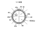
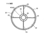
- FIG. 2B is a cross-sectional view taken along line VV of FIG. 2A.
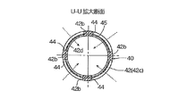
- the expanded sectional view according to the UU arrow line of FIG. 3A Sectional drawing according to the VV arrow line of FIG. 3A.
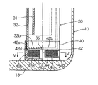
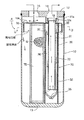
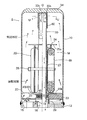
- First Embodiment 1A and 1B show a first embodiment of an accumulator according to the present invention
- FIG. 1A is a longitudinal sectional view
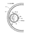
- FIG. 1B is an enlarged sectional view taken along the line UU in FIG. 1A.
- the accumulator 1 of the illustrated embodiment is used, for example, in a refrigeration cycle constituting a car air conditioner for a car, and has a bottomed cylindrical tank 10 made of metal such as stainless steel or aluminum alloy, and the upper surface opening of the tank 10 Is airtightly closed by the same metal lid member 12.
- the accumulator 1 is installed, for example, vertically as shown in the drawing, that is, with the lid member 12 on the upper side and the bottom 13 of the tank 10 on the lower side.
- An inlet 15 and a stepped outlet 16 are juxtaposed in the lid member 12.
- the lower portion of the outflow port 16 is formed by a stepped portion formed in the lower convex portion 12a which is provided to project downward to the lid member 12, and the lower surface of the lower convex portion 12a has a diameter slightly smaller than the inner diameter of the tank 10.
- a bowl-like or inverted thin bowl-like gas-liquid separator 18 is disposed in a state where a part of the upper surface is in contact.
- the lower end of the outlet 16 is connected to the upper end of an outlet pipe 30 described later.
- the outflow pipe 30 is a double formed of an inner pipe 31 whose upper end 31 a is expanded and fixed at a lower portion of the outflow port 16 and suspended, and a bottomed outer pipe 32 disposed on the outer periphery of the inner pipe 31. It has a tube structure.
- a gas-phase refrigerant lower feed passage 36 is formed between the outer pipe 32 and the inner pipe 31, and the upper end of the outer pipe 32 (a portion between the inner pipe 31 and the outer pipe 32) is a gas-phase refrigerant suction port 37. .
- the upper end portion 31a (before the expansion) of the inner pipe 31 functions as a filter member described later, and is an upper strainer 40 '(bottom plate portion 42c of the upper strainer) provided at the gas phase refrigerant suction port 37 of the outflow pipe 30.
- the lower end portion of the outer pipe 32 is internally fixed by press-fitting or the like to an upper portion 42 a with an inner circumferential step in a case 42 of an oil strainer 40 (hereinafter referred to as a lower strainer 40) described later.
- the lower end of the inner pipe 31 is positioned slightly above the bottom 32 b of the outer pipe 32, and the upper end of the outer pipe 32 is positioned lower than the lid member 12 by a predetermined distance.
- An oil return hole 35 is formed in the center of the bottom 32 b of the outer pipe 32.
- the hole diameter of the oil return hole 35 is set to, for example, about 1 mm.
- the inner pipe 31 has a plurality of (three in the illustrated example) plate-like ribs 38 along the longitudinal direction (vertical direction) and at equal angular intervals, as can be seen by referring to FIG. 1A together with FIG. 1A.
- the outer pipe 32 is externally fitted and fixed to the outside of the plurality of plate-like ribs 38 in a manner of being press-fitted.
- the plate-like rib 38 has a length from the lower end of the inner pipe 31 to a predetermined position in the height direction of the outer pipe 32, but the upper end extends upward from the upper end of the outer pipe 32 The upper end surface may abut on the bottom plate portion 42c of the upper strainer 40 '. Thereby, a predetermined gap is secured between the inner pipe 31 and the outer pipe 32, and the gas phase refrigerant lower feed passage 36 is formed.
- the plate-like rib 38 may be formed on at least one of the inner pipe 31 and the outer pipe 32.
- the plate-like rib 38 is formed on (the inner periphery of) the outer pipe 32.
- the inner pipe 31 may be inserted and fixed in a manner of being press-fitted into the inside of the frame.
- the inner pipe 31, the outer pipe 32, and the plate-like rib 38 may be integrally formed by extrusion molding using a synthetic resin material, an aluminum material or the like. That is, the above-mentioned double-pipe structure may be an integrally molded article using an extruded aluminum material or the like.
- the lower strainer 40 is placed on and fixed to the bottom of the tank 10, and as shown in FIGS. 2A and 2B, the bottomed cylindrical case 42 made of a synthetic resin and the case 42 are fixed. It consists of a cylindrical mesh filter 45 integrated by insert molding.
- the mesh filter 45 is made of, for example, a wire mesh, a synthetic resin mesh material, or the like.
- the case 42 of the lower strainer 40 is erected at equal angular intervals on the outer periphery of the upper portion 42a with a step on the inner periphery where the lower end portion of the outer pipe 32 is fixedly fitted, a bottom plate portion 42c, and the bottom plate portion 42c. It has four columnar parts 42b, and annular belt-like mesh end embedded parts 42d, 42d having a predetermined thickness and band width including upper and lower ends of the columnar parts 42b. .
- the upper and lower end portions of the mesh filter 45 are integrated and sealed in the upper and lower mesh end embedded portions 42d, 42d at the time of insert molding, and the columnar portion 42b in the mesh filter 45 is also inserted at the time of insert molding It is integrated and sealed to 42b.
- four windows 44 having a rectangular shape in a side view are defined by the four columnar parts 42b and the upper and lower mesh end embedded parts 42d, 42d, and the mesh filter 45 is stretched on the respective windows 44. become.
- a bag 68 filled with a desiccant M for absorbing and removing water in the refrigerant is disposed on the lower side of the tank 10 and along the inner periphery of the tank 10. ing.
- This bag 68 is made of a cloth-like body such as felt having breathability and water permeability as well as the required shape-retaining property, in which a granular desiccant M is substantially filled.
- the upper strainer 40 'a a filter member that allows the gas phase refrigerant to pass through the gas phase refrigerant suction port 37 of the outflow pipe 30 but can substantially block foreign substances in the liquid phase refrigerant.
- an upper strainer 40 'having the same basic configuration as the lower strainer 40 provided at the lower end of the outflow pipe 30 (but slightly longer in the vertical direction) is provided at the upper end of the outer pipe 32 of the outflow pipe 30 ing. Note that, in the upper strainer 40 ′, parts corresponding to the lower strainer 40 are given the same reference numerals.
- the upper strainer 40 is provided at its bottom plate portion 42c with a through hole 39 through which the upper end portion 31a of the inner pipe 31 passes, with the bottom plate portion 42c facing up, that is, upside down with the lower strainer 40. And the upper end portion of the inner pipe 31 and the upper end portion of the outer pipe 32 so as to be press-fitted and fixedly held, and held between the upper end portion of the outer pipe 32 of the outflow pipe 30 and the gas-liquid separator 18 .
- the low-temperature low-pressure gas-liquid mixed refrigerant from the evaporator is introduced through the inlet 15, and the introduced refrigerant is It collides with the body 18 and is radially diffused to be separated into a liquid phase refrigerant and a gas phase refrigerant.
- the liquid phase refrigerant (including oil) flows down along the inner peripheral surface of the tank 10 and accumulates in the lower space of the tank 10, and the gas phase refrigerant is meshed with the mesh of the upper strainer 40 ′ provided on the outer pipe 32.
- the gas is drawn to the suction side of the compressor via the inner space of the gas phase refrigerant lower feed passage 36 ⁇ inner pipe 31 formed between the inner pipe 31 and the outer pipe 32 through the filter 45 and circulated.
- the oil accumulated in the lower space of the tank 10 together with the liquid phase refrigerant moves to the bottom 13 side of the tank 10 due to the difference in specific gravity and the property with the liquid phase refrigerant.
- the liquid phase refrigerant on the bottom portion 13 side of the tank 10 containing the oil is sucked little by little by the gas phase refrigerant sucked to the suction side of the compressor through the outflow pipe 30, and the mesh filter 45 of the lower strainer 40 ⁇ From the oil return hole 35 ⁇ the inner space of the inner pipe 31, the gas phase refrigerant is returned to the suction side of the compressor and circulated.
- the mesh filter 45 foreign matter such as sludge and metal powder is captured, and the foreign matter is removed from the circulating refrigerant (including oil).
- the gas-phase refrigerant suction port 37 in the outflow pipe 30 is provided with an upper strainer 40 'having the same basic configuration as the lower strainer 40 usually used as a filter member.
- the upper strainer 40 '(of the mesh filter 45) can substantially capture foreign matter in the liquid phase refrigerant, so the liquid phase refrigerant is sucked up and the liquid level becomes high, or the liquid is caused by vibration, running on a slope or the like.
- the amount of the liquid-phase refrigerant flowing from the gas-phase refrigerant suction port 37 of the outflow pipe 30 (the amount of liquid back) can be reduced by the action of the filter member (upper strainer 40 ′).
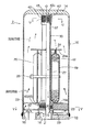
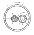
- Second Embodiment 3A to 3C show a second embodiment of the accumulator according to the present invention, wherein FIG. 3A is a partially cutaway half longitudinal sectional view, FIG. 3B is an enlarged sectional view according to the line of arrows U-U in FIG. 3A, and FIG. It is sectional drawing according to the VV arrow line of view.
- the accumulator 2 of the second embodiment parts corresponding to the respective parts of the accumulator 1 of the first embodiment are given the same reference numerals, and redundant description will be omitted, and in the following, differences will be mainly described. .
- the accumulator 2 of the illustrated embodiment has a cylindrical tank 10 with a top surface portion 14 with an open lower surface made of metal such as stainless steel or aluminum alloy, and the lower surface opening of the tank 10 is a bottom lid member made of the same metal. It is closed airtightly by 12.
- the tank 10 and the like are arranged upside down from the accumulator 1 of the first embodiment, and for example, the bottom lid member 12 is on the lower (ground) side and the top of the tank 10 as shown. It is installed with the surface portion 14 on the top side.
- An inlet 15 and a stepped outlet 16 are juxtaposed in the bottom lid member 12 so as to pass through the bottom lid member 12 and open up and down.
- the outlet 16 is provided at the center of the bottom lid member 12 (on the center line O of the tank 10), and the inlet 15 is provided on the left side thereof.
- An outlet pipe 30 formed of a straight pipe (a straight pipe along a center line) for guiding the gas phase refrigerant from the upper portion of the tank 10 to the outlet 16 is continuously provided in the outlet 16 continuously.
- the upper end side opening (the vapor phase refrigerant suction port 37) is positioned slightly below the top surface portion 14 of the tank 10.
- the outflow pipe 30 may be integrally formed with the bottom lid member 12 or may be separately formed and fixed by caulking or the like.
- a short cylindrical internal fitting connection 19 in which an external thread for connecting the built-in unit 20 to be described later in a screw-on manner is formed on the upper surface side central portion (portion including the central outlet 16) of the bottom lid member 12. Is projected.
- a built-in unit 20 is disposed in the tank 10.
- the built-in unit 20 is made of, for example, a synthetic resin, and has an annular disc-like gas-liquid separation promoting plate 22 at the lower part thereof.
- the refrigerant flowing into the tank 10 from the inflow port 15 collides and diffuses radially, and the collision-diffused refrigerant is the outer peripheral surface of the tank 10 and the outer periphery of the gas-liquid separation promoting plate 22
- the outer diameter is slightly smaller than the inner diameter of the tank 10 and the inner diameter thereof is an annular disc substantially equal to the inner diameter of the lower strainer 40 described later so as to flow upward through between the surfaces and
- the lower surface is disposed above the upper surface of the bottom lid member 12 (the inlet 15 at a predetermined distance) such that the lower surface faces the inlet 15.
- a short cylindrical external fitting connection is formed at the center of the lower surface side of the gas-liquid separation promoting plate 22 with a female screw portion screwed to the male screw portion of the inner fitting connection portion 19 provided on the bottom lid member 12.
- the portion 29 protrudes downward. Since the bottom lid member 12 and the built-in unit 20 can be connected by screwing in this way, assembly is easy and easy.
- a lower strainer 40 is provided at the center on the upper surface side of the gas-liquid separation promoting plate 22 so as to surround the lower end portion of the outflow pipe 30, and four places on the upper surface side outer periphery of the gas-liquid separation promoting plate 22. Are erected at equal angular intervals (that is, 90.degree. Intervals), and the outer peripheral portion of the reinforced upright plate portion 23 is in contact with the inner periphery of the tank 10. As shown in FIG. In the illustrated example, the reinforcing upright plate portion 23 is provided on the front, rear, left, and right of the outer periphery on the upper surface side of the gas-liquid separation promoting plate 22. It is arrange
- the bag holder 24 is integrally provided.
- the bobbin-like bag holding portion 24 is configured to wrap the desiccant M-containing bag 69 in a cylindrical shape or a C shape in plan view around the long cylindrical portion 27 and wind and hold the binding band 28 around the outer periphery thereof. ing. In this case, the upper end and the lower end of the held bag 69 are slightly pressed against the pair of upper and lower flanges 25 a and 25 b of the bag holding unit 24.
- the bag 69 housed in the bag holding portion 24 is made of a cloth-like body such as felt having air permeability, water permeability, and required shape retention, in which the granular desiccant M is substantially full. It is filled and here has a height of about half to about 2/3 of the tank 10.
- the lower strainer 40 is integrally provided on the gas-liquid separation promoting plate 22, but basically has substantially the same configuration as that of the first embodiment (corresponding part And a cylindrical mesh filter 45 and a case 42 to which the mesh filter 45 is fixed.
- the mesh filter 45 is made of, for example, a wire mesh, a synthetic resin mesh material, or the like.
- the case 42 is configured by upper and lower annular disc portions and inner peripheral end portions (four places) of the reinforcing upright plate portion 23 positioned therebetween. That is, four windows 44 having a rectangular shape in a side view are defined between four columnar parts (the inner peripheral end of the reinforced upright plate part 23) 42b, and a mesh filter 45 is stretched around the respective windows 44. It will be.
- the mesh filter 45 may be integrated by insert molding at the time of molding of the case 42 (built-in unit 20).
- An oil return hole 35 is provided near the lower end portion of the outflow pipe 30 integrally provided on the bottom cover member 12 by integral molding or caulking.
- the hole diameter of the oil return hole 35 is set to, for example, about 1 mm.
- an upper strainer 40 ' having the same basic configuration as that of the first embodiment is provided. Specifically, an upper strainer 40 'is sandwiched and fixed between the upper end of the outflow pipe 30 and the top surface 14 of the tank 10.
- the upper strainer 40 ' is in a state where the bottom plate portion 42c is in contact or in pressure contact with the top surface portion 14, that is, the upper strainer of the outflow pipe 30 (gas phase refrigerant suction port 37) is upside down with the lower strainer 40 It is inserted and fixed and held.
- the low-temperature low-pressure gas-liquid mixed refrigerant from the evaporator is introduced upward into the tank 10 through the inlet port 15, and the introduced refrigerant promotes gas-liquid separation.
- the refrigerant diffused and staying radially on the lower surface of the plate 22 gradually diffuses through the gap between the inner peripheral surface of the tank 10 and the outer peripheral surface of the gas-liquid separation promoting plate 22 and moves upward. As a result, rectification is performed, and the liquid-phase refrigerant and the gas-phase refrigerant are effectively separated.
- the liquid phase refrigerant (including oil) accumulates in the lower space of the tank 10, and the gas phase refrigerant rises in the upper space of the tank 10, and the upper space of the tank 10 ⁇ the mesh filter 45 of the upper strainer 40 ' ⁇ The inside space of the outflow pipe 30 ⁇ The air is sucked into the suction side of the compressor via the outflow port 16 and circulated.
- the oil accumulated in the lower space of the tank 10 together with the liquid phase refrigerant moves to the bottom cover member 12 side of the tank 10 due to the difference in specific gravity or property with the liquid phase refrigerant, and the compressor via the outflow pipe 30
- the gas-phase refrigerant sucked to the suction side of the compressor is sucked, and is returned to the suction side of the compressor along with the gas-phase refrigerant through the mesh filter 45 of the strainer 40 ⁇ oil return hole 35 and circulated.
- the mesh filter 45 When passing through the mesh filter 45, foreign matter such as sludge and metal powder is captured, and the foreign matter is removed from the circulating refrigerant (including oil).
- the refrigerant in the gas-liquid mixed state is introduced upward into the tank 10 from the inlet 15 provided at the lower part of the tank 10, and the lower surface of the gas-liquid separation promoting plate 22 While being diffused radially while staying on the side, the diffused refrigerant is moved upward through the gap between the inner peripheral surface of the tank 10 and the outer peripheral surface of the gas-liquid separation promoting plate 22 to separate the gas-liquid. Promoted.
- the liquid-phase refrigerant is agitated by rising of the gas-phase refrigerant in the liquid above the gas-liquid separation promoting plate 22 in particular, bumping phenomenon in which the liquid-phase refrigerant bursts explosively at a start of the compressor. And it becomes possible to control generation
- the inlet 15 is provided in the lower part of the tank 10, and the gas-liquid separation promoting plate 22 may be disposed above the inlet 15 in the tank 10. Therefore, the configuration of the accumulator 2 is simplified. At the same time, cost reduction, downsizing and the like can be achieved.
- the gas-phase refrigerant suction port 37 in the outflow pipe 30 is provided with an upper strainer 40 'having the same basic configuration as the lower strainer 40 usually used as a filter member. ing.
- the upper strainer 40 '(of the mesh filter 45) can substantially capture foreign matter in the liquid phase refrigerant, so the liquid phase refrigerant is sucked up and the liquid level becomes high, or the liquid is caused by vibration, running on a slope or the like.
- the amount of the liquid-phase refrigerant flowing from the gas-phase refrigerant suction port 37 of the outflow pipe 30 (the amount of liquid back) can be reduced by the action of the filter member (upper strainer 40 ′).
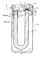
- Third Embodiment 4A and 4B show a third embodiment of the accumulator according to the present invention
- FIG. 4A is a longitudinal sectional view
- FIG. 4B is an enlarged sectional view taken along the line U--U of FIG. 4A.
- the parts corresponding to the respective parts of the accumulator 1 of the first embodiment are given the same reference numerals to omit redundant description, and in the following, differences will be mainly described. .
- a metal U-shaped pipe made of aluminum, SUS, or copper is used as the outflow pipe 60.
- a bowl-shaped or inverted thin bowl-shaped gas-liquid separator 18 having a diameter smaller than the inner diameter of the tank 10 is externally fitted to one end 61 side of the U-shaped outlet pipe 60 connected to the lower portion of the outlet 16
- An annular protrusion 61 f compressed and bent by bulge forming or the like is provided.
- a cleaning strainer 65 having a hemispherical mesh filter 66 with a bowl-shaped portion 65 a made of, for example, SUS is disposed.
- a plurality of (for example, a total of four at 90 ° intervals) rod-shaped portions are projected downward on the lower surface side of the lower convex portion 12 a, and the rod-shaped portions are provided on the top surface 18 a of the gas-liquid separator 18.
- the same number (for example, a total of four at intervals of 90 °) of round holes through which can be inserted is formed.
- the plurality of rod portions are passed through the respective round holes, and the plurality of rod portions are melted and crushed by an ultrasonic welder or the like It is done by making it form (rivet-like crushing part 64).
- An oil return hole 63 is provided at the lowermost end of the U-shaped outflow pipe 60.
- the other end (upward opening) 62 of the U-shaped outflow pipe 60 is a gas phase refrigerant suction port 67, and the gas phase refrigerant passes through the gas phase refrigerant suction port 67 but the liquid phase refrigerant
- An upper strainer 40 ' having the same basic configuration as that of the first embodiment as a filter member capable of substantially blocking is provided. Specifically, an upper strainer 40 'is sandwiched and fixed between the upper end of the other end 62 of the outflow pipe 60 and the top surface 18a of the gas-liquid separator 18.
- the upper strainer 40 ' is externally fitted and mounted on the other end 62 (gas-phase refrigerant suction port 67) of the outflow pipe 60 in a state where the bottom plate portion 42c is in contact or in pressure contact with the top surface 18a of the gas-liquid separator 18 It is held fixed.
- the low-temperature low-pressure gas-liquid mixed refrigerant from the evaporator is introduced through the inlet 15, and the introduced refrigerant is It collides with the body 18 and is radially diffused to be separated into a liquid phase refrigerant and a gas phase refrigerant.
- the liquid phase refrigerant (including oil) flows down along the inner peripheral surface of the tank 10 and accumulates in the lower space of the tank 10, and the gas phase refrigerant is provided on the other end 62 side of the outflow pipe 60. It passes through 40 '(the mesh filter 45), and is sucked and circulated to the suction side of the compressor through the inner space of the outflow pipe 60 ⁇ (the mesh filter 66) of the purification strainer 65.
- the oil accumulated in the lower space of the tank 10 together with the liquid phase refrigerant moves to the bottom 13 side of the tank 10 due to the difference in the specific gravity and the property with the liquid phase refrigerant.
- the liquid phase refrigerant on the bottom portion 13 side of the tank 10 containing the oil is sucked little by little by the gas phase refrigerant sucked to the suction side of the compressor through the outflow pipe 60, and the oil return hole 63 ⁇ the outflow pipe 60
- the internal space is returned to the suction side of the compressor along with the gas phase refrigerant through the purification strainer 65 and circulated.
- foreign matter such as sludge and metal powder is captured, and the foreign matter is removed from the circulating refrigerant (including oil).
- an upper strainer 40 'as a filter member is provided at the gas phase refrigerant suction port 67 in the outflow pipe 60.
- the upper strainer 40 '(of the mesh filter 45) can substantially capture foreign matter in the liquid phase refrigerant, so the liquid phase refrigerant is sucked up and the liquid level becomes high, or the liquid is caused by vibration, running on a slope or the like. Even if the liquid surface of the phase refrigerant wave rises and bumping occurs and the liquid surface of the liquid phase refrigerant temporarily rises, foreign substances in the liquid phase refrigerant are captured by the upper strainer 40 ', The foreign matter is prevented from flowing to the compressor side. Therefore, there is no concern that adversely affects the compressor, and there is no concern that the life of the refrigeration cycle is reduced.
- the amount of the liquid-phase refrigerant flowing into the interior of the outflow pipe 60 (the amount of liquid back) can be reduced by the action of the filter member (upper strainer 40 ′).
- FIG. 5A and 5B show a fourth embodiment of the accumulator according to the present invention
- FIG. 5A is a partially cutaway longitudinal sectional view
- FIG. 5B is an enlarged sectional view taken along the line U--U of FIG. 5A.
- the parts corresponding to the respective parts of the accumulator 1 of the first embodiment are given the same reference numerals to omit redundant description, and in the following, differences will be mainly described. .
- the inner pipe 31 of the accumulator 4 has a plurality of (three in the illustrated example) along the longitudinal direction (vertical direction) and at equal angular intervals, as can be understood well with reference to FIG.
- the plate-like rib 38 is provided so as to project radially, and the outer pipe 32 is extrapolated and fixed to the outside of the plurality of plate-like ribs 38 in a manner of press-fitting.
- the upper end of the plate-like rib 38 is extended upward from the upper end of the outer pipe 32 so that the upper end face abuts on the top surface 18 a of the gas-liquid separator 18.
- the lower end portion of the outer pipe 32 is squeezed into a funnel shape by a spinning process or the like, and an oil return hole 35 is formed at the center thereof.
- the lower strainer 40 and the upper strainer 40 ′ in the first embodiment are omitted, and the entire outer periphery of the outer pipe 32 is covered, and the gas-liquid separator 18 is A cloth-like body 70 such as a felt having a length from the top surface 18a to the bottom surface of the bottom portion 13 of the tank 10 is wound or extrapolated.
- the cloth-like body 70 is provided with a cylindrical pipe extrapolation portion 72 which is extrapolated and fixed to the outer periphery of the outer pipe 32, and also contains a desiccant M for absorbing and removing the water in the refrigerant.
- a cylindrical desiccant storage unit 75 is provided.
- the pipe extrapolation portion 72 itself can hold a substantially cylindrical shape, and the portion of the bag-like body or the cylindrical body at the lower portion (the portion covering the periphery of the oil return hole 35) is the first one. It serves as the lower strainer 40 in the embodiment.
- the lower portion of the pipe extrapolation portion 72 can function as the lower strainer 40.
- the portion of the bag-like body or the tubular body at the upper portion (above the upper end of the outer pipe 32) of the pipe extrapolation portion 72 can serve as the upper strainer 40 'of the first embodiment.
- the low-temperature low-pressure gas-liquid mixed refrigerant introduced from the evaporator is introduced through the inlet 15, and the introduced refrigerant collides with the gas-liquid separator 18 and is radially diffused to form the liquid-phase refrigerant and the gas-phase refrigerant. It is separated into the phase refrigerant.
- a liquid phase refrigerant (including oil) flows down along the inner circumferential surface of the tank 10 and accumulates in the lower space of the tank 10, and the gas phase refrigerant is a pipe surrounding the gas phase refrigerant suction port 37 of the outflow pipe 30.
- the oil accumulated in the lower space of the tank 10 together with the liquid phase refrigerant moves to the bottom 13 side of the tank 10 due to the difference in specific gravity and the property with the liquid phase refrigerant.
- the liquid phase refrigerant on the bottom portion 13 side of the tank 10 containing oil is sucked little by little by the gas phase refrigerant sucked to the suction side of the compressor through the outflow pipe 30, and is made of a cloth-like body 70 such as felt
- the lower part of the pipe extrapolation portion 72 ⁇ oil return hole 35 ⁇ the inner space of the inner pipe 31 is returned to the suction side of the compressor together with the gas phase refrigerant and circulated.
- the cloth-like body 70 such as felt has air permeability and water permeability, it is added to the pipe extrapolation portion 72 in the cloth-like body 70 as in the present embodiment to absorb the moisture in the refrigerant.
- the desiccant storage unit 75 for storing the desiccant M to be removed is provided, the desiccant storage unit 75 serves as a bag, so a bag and its fixing means (such as a binding band) are separately prepared. There is no need, and cost-effectiveness is further enhanced.
- a foam material may be used, and as the foam material, those made of commercially available synthetic resin, rubber, ceramic or the like can be used.
- the cloth-like body 70 wound around or extrapolated to the outer periphery of the outer pipe 32 serves as a boiling stone. That is, at the time of startup of the compressor, the cloth-like body 70 (gas therein) becomes a starting point when the liquid-phase refrigerant boils and vaporizes, and air bubbles are gradually released, that is, the liquid-phase refrigerant gradually It will be in the state to vaporize. Therefore, the boiling of the liquid-phase refrigerant proceeds gradually, and as a result, it is possible to effectively suppress the bumping phenomenon that the liquid-phase refrigerant boils explosively at a stroke and the generation of the impulsive sound associated therewith.
- the accumulator 4 of the present embodiment it is only necessary to add a simple configuration in which the cloth-like body 70 is wound or extrapolated on the outer periphery of the outer pipe 32. No cost will be incurred, and it will be extremely cost effective.
- the upper and lower bag-like members or the tubular portion of the pipe extrapolation portion 72 of the cloth-like member 70 also functions as the lower and upper strainers 40 and 40 '.
- the amount of liquid back can also be reduced like the above-mentioned embodiment.
- FIG. 6A to 6D show a fifth embodiment of the accumulator according to the present invention
- FIG. 6A is a partially cutaway half longitudinal sectional view
- FIG. 6B is a partial side view showing an upper end portion (gas phase refrigerant suction port) of the outflow pipe.
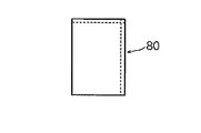
- FIG. 6C is a view showing a bag-like body as a filter member
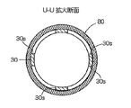
- FIG. 6D is an enlarged cross-sectional view taken along the line UU in FIG. 6A.
- the parts corresponding to the respective parts of the accumulator 2 of the second embodiment are given the same reference numerals, and redundant description will be omitted, and in the following, differences will be mainly described. .
- the accumulator 5 of the illustrated embodiment is different from the accumulator 2 of the second embodiment in that, as shown in FIG. 6B and FIG. Rectangular notches 30s are provided at equal angular intervals, and a bag-like body (or a cylindrical body) 80 as shown in FIG. 6C is used as the filter member instead of the upper strainer 40 '.
- the bag-like body 80 is formed by sewing a cloth-like waterproof moisture-permeable material such as Gore-Tex (registered trademark) into a bag-like (or tubular) shape, and covers all the notches 30s and the top opening of the outflow pipe 30. As described above, the upper end of the outflow pipe 30 is covered.
- the upper surface of the bag-like body 80 is pressed against the top surface portion 14 of the tank 10. In other words, the bag-like body 80 is sandwiched by the upper end portion of the outflow pipe 30 and the top surface portion 14 of the tank 10.
- a bag-like body (or tubular body) 80 made of a waterproof moisture-permeable material is covered so as to cover all the notch portions 30s and the top opening of the outflow pipe 30 made of a straight pipe.
- FIG. 7 is a longitudinal sectional view showing a sixth embodiment of the accumulator according to the present invention.
- the accumulator 6 of the sixth embodiment parts corresponding to the respective parts of the accumulator 3 of the third embodiment are given the same reference numerals, and redundant description will be omitted, and in the following, differences will be mainly described. .
- the accumulator 6 of the illustrated embodiment is different from the accumulator 3 of the third embodiment in that the gas phase refrigerant suction port 67 is substantially similar to that of the fifth embodiment at the other end 62 of the outflow pipe 60 in side view. Rectangular notches 60s are provided at equal angular intervals, and a bag-like member (or a cylindrical member) 80 having the same configuration as that of the fifth embodiment is used as the filter member instead of the upper strainer 40 '. There is.
- the bag-like body 80 is formed by sewing a cloth-like waterproof moisture-permeable material such as Gore-Tex (registered trademark) into a bag-like (or cylindrical) shape, and covers all the notches 60s and the top opening of the outflow pipe 60 As such, the other end 62 of the outflow pipe 60 is covered.
- the upper surface of the bag-like body 80 is pressed against the top surface 18 a of the gas-liquid separator 18. In other words, the bag-like body 80 is sandwiched between the other end 62 of the outflow pipe 60 and the top surface 18 a of the gas-liquid separator 18.
- a bag-like body (or a tubular body) 80 made of a waterproof moisture-permeable material is covered so as to cover all the cutouts 60s and the top surface opening of the outflow pipe 60 made of a U-shaped tube.
- an upper strainer 40 ' provided with the mesh filter adopted in the above embodiment, a pipe extrapolation portion 72 made of a cloth-like material having water permeability and air permeability such as felt, Gore-Tex ( Of course, it may be something other than the bag-like body 80 and the like made of a waterproof moisture-permeable material such as a registered trademark), and the configuration of them may be variously changed. Further, it goes without saying that the configuration of the outflow pipe may be one other than the double pipe structure, the straight pipe, and the U-shaped pipe.
Landscapes
- Engineering & Computer Science (AREA)
- Chemical & Material Sciences (AREA)
- Analytical Chemistry (AREA)
- Power Engineering (AREA)
- Physics & Mathematics (AREA)
- Mechanical Engineering (AREA)
- Thermal Sciences (AREA)
- General Engineering & Computer Science (AREA)
- Air-Conditioning For Vehicles (AREA)
Priority Applications (3)
| Application Number | Priority Date | Filing Date | Title |
|---|---|---|---|
| CN202211115277.XA CN115468340A (zh) | 2017-12-01 | 2018-10-22 | 储液器 |
| CN201880077535.5A CN111433536A (zh) | 2017-12-01 | 2018-10-22 | 储液器 |
| EP18883709.0A EP3677857A4 (en) | 2017-12-01 | 2018-10-22 | ACCUMULATOR |
Applications Claiming Priority (2)
| Application Number | Priority Date | Filing Date | Title |
|---|---|---|---|
| JP2017-232083 | 2017-12-01 | ||
| JP2017232083A JP6815036B2 (ja) | 2017-12-01 | 2017-12-01 | アキュームレータ |
Publications (1)
| Publication Number | Publication Date |
|---|---|
| WO2019107011A1 true WO2019107011A1 (ja) | 2019-06-06 |
Family
ID=66664980
Family Applications (1)
| Application Number | Title | Priority Date | Filing Date |
|---|---|---|---|
| PCT/JP2018/039210 Ceased WO2019107011A1 (ja) | 2017-12-01 | 2018-10-22 | アキュームレータ |
Country Status (4)
| Country | Link |
|---|---|
| EP (1) | EP3677857A4 (enExample) |
| JP (1) | JP6815036B2 (enExample) |
| CN (2) | CN115468340A (enExample) |
| WO (1) | WO2019107011A1 (enExample) |
Cited By (1)
| Publication number | Priority date | Publication date | Assignee | Title |
|---|---|---|---|---|
| CN111637655A (zh) * | 2020-07-03 | 2020-09-08 | 聊城新时代新能源设备股份有限公司 | 一种新型低温补气增焓压缩系统 |
Families Citing this family (1)
| Publication number | Priority date | Publication date | Assignee | Title |
|---|---|---|---|---|
| CN112880252A (zh) * | 2021-02-07 | 2021-06-01 | 上海创历制冷设备有限公司 | 一种气液分离器 |
Citations (13)
| Publication number | Priority date | Publication date | Assignee | Title |
|---|---|---|---|---|
| JPH05215445A (ja) * | 1991-04-12 | 1993-08-24 | Nippondenso Co Ltd | 冷媒中の水分除去装置 |
| EP1044836A1 (de) * | 1999-04-14 | 2000-10-18 | Hansa Metallwerke Ag | Akkumulator fur eine nach dem "Orifice"-Prinzip arbeitende Klimaanlage, insbesonder Fahrzeugklimaanlage |
| JP2001041841A (ja) * | 1999-07-28 | 2001-02-16 | Denso Corp | ガス洩れ検知装置用プローブ |
| US6395074B1 (en) * | 2000-05-16 | 2002-05-28 | Stanhope Products Company | Desiccant bag with integrated filter and method of making same |
| US20060196219A1 (en) * | 2005-03-01 | 2006-09-07 | Halla Climate Control Canada Inc. | Accumulator with full-flow filtering |
| DE102007028591A1 (de) * | 2007-06-19 | 2008-12-24 | Behr Gmbh & Co. Kg | Akkumulator, insbesondere für eine Kraftfahrzeug- Klimaanlage |
| JP2008309434A (ja) * | 2007-06-16 | 2008-12-25 | Calsonic Kansei Corp | アキュムレータ |
| EP2031325A2 (de) * | 2007-07-13 | 2009-03-04 | Behr GmbH & Co. KG | Akkumulator, insbesondere für eine Klimaanlage, mit Schmutzfänger |
| EP2136163A1 (de) * | 2008-06-19 | 2009-12-23 | Behr GmbH & Co. KG | Kältemittelsammler mit Flüssigkeitsabscheider |
| CN102401515A (zh) * | 2010-09-13 | 2012-04-04 | 乐金电子(天津)电器有限公司 | 密闭型压缩机的储液罐结构 |
| JP2014077606A (ja) | 2012-10-12 | 2014-05-01 | Fuji Koki Corp | アキュムレータ |
| JP2017020670A (ja) | 2015-07-07 | 2017-01-26 | 株式会社不二工機 | アキュームレータ |
| JP2017026192A (ja) * | 2015-07-17 | 2017-02-02 | 株式会社不二工機 | アキュームレータ |
Family Cites Families (10)
| Publication number | Priority date | Publication date | Assignee | Title |
|---|---|---|---|---|
| JPH11182987A (ja) * | 1997-12-25 | 1999-07-06 | Fujikoki Corp | レシーバドライヤ |
| KR200231147Y1 (ko) * | 2001-01-19 | 2001-07-19 | 김영희 | 오일분리기 |
| US6951062B2 (en) * | 2003-12-24 | 2005-10-04 | Advanced Test Products, Inc. | Method and apparatus for restricting foreign objects from entering a device |
| CN202304149U (zh) * | 2011-10-26 | 2012-07-04 | 广东芬尼克兹节能设备有限公司 | 带双重过滤网的气液分离器 |
| JP6068938B2 (ja) * | 2012-11-08 | 2017-01-25 | 株式会社不二工機 | アキュムレータ |
| CN203385246U (zh) * | 2013-05-17 | 2014-01-08 | 山东格瑞德集团有限公司 | 一种闪蒸罐的制冷剂二级过滤分离结构 |
| CN103808090B (zh) * | 2013-10-25 | 2016-05-18 | 珠海凌达压缩机有限公司 | 一种油分离器以及使用该油分离器的压缩机及制冷系统 |
| CN204345983U (zh) * | 2014-08-28 | 2015-05-20 | 麦克维尔空调制冷(武汉)有限公司 | 具有双重分离作用的立式油气分离器 |
| JP6594685B2 (ja) * | 2015-07-13 | 2019-10-23 | 株式会社不二工機 | アキュームレータ |
| CN206146071U (zh) * | 2016-11-11 | 2017-05-03 | 浙江富源制冷设备股份有限公司 | 双回油管油分离器 |
-
2017
- 2017-12-01 JP JP2017232083A patent/JP6815036B2/ja active Active
-
2018
- 2018-10-22 CN CN202211115277.XA patent/CN115468340A/zh active Pending
- 2018-10-22 CN CN201880077535.5A patent/CN111433536A/zh active Pending
- 2018-10-22 WO PCT/JP2018/039210 patent/WO2019107011A1/ja not_active Ceased
- 2018-10-22 EP EP18883709.0A patent/EP3677857A4/en active Pending
Patent Citations (13)
| Publication number | Priority date | Publication date | Assignee | Title |
|---|---|---|---|---|
| JPH05215445A (ja) * | 1991-04-12 | 1993-08-24 | Nippondenso Co Ltd | 冷媒中の水分除去装置 |
| EP1044836A1 (de) * | 1999-04-14 | 2000-10-18 | Hansa Metallwerke Ag | Akkumulator fur eine nach dem "Orifice"-Prinzip arbeitende Klimaanlage, insbesonder Fahrzeugklimaanlage |
| JP2001041841A (ja) * | 1999-07-28 | 2001-02-16 | Denso Corp | ガス洩れ検知装置用プローブ |
| US6395074B1 (en) * | 2000-05-16 | 2002-05-28 | Stanhope Products Company | Desiccant bag with integrated filter and method of making same |
| US20060196219A1 (en) * | 2005-03-01 | 2006-09-07 | Halla Climate Control Canada Inc. | Accumulator with full-flow filtering |
| JP2008309434A (ja) * | 2007-06-16 | 2008-12-25 | Calsonic Kansei Corp | アキュムレータ |
| DE102007028591A1 (de) * | 2007-06-19 | 2008-12-24 | Behr Gmbh & Co. Kg | Akkumulator, insbesondere für eine Kraftfahrzeug- Klimaanlage |
| EP2031325A2 (de) * | 2007-07-13 | 2009-03-04 | Behr GmbH & Co. KG | Akkumulator, insbesondere für eine Klimaanlage, mit Schmutzfänger |
| EP2136163A1 (de) * | 2008-06-19 | 2009-12-23 | Behr GmbH & Co. KG | Kältemittelsammler mit Flüssigkeitsabscheider |
| CN102401515A (zh) * | 2010-09-13 | 2012-04-04 | 乐金电子(天津)电器有限公司 | 密闭型压缩机的储液罐结构 |
| JP2014077606A (ja) | 2012-10-12 | 2014-05-01 | Fuji Koki Corp | アキュムレータ |
| JP2017020670A (ja) | 2015-07-07 | 2017-01-26 | 株式会社不二工機 | アキュームレータ |
| JP2017026192A (ja) * | 2015-07-17 | 2017-02-02 | 株式会社不二工機 | アキュームレータ |
Non-Patent Citations (1)
| Title |
|---|
| See also references of EP3677857A4 |
Cited By (1)
| Publication number | Priority date | Publication date | Assignee | Title |
|---|---|---|---|---|
| CN111637655A (zh) * | 2020-07-03 | 2020-09-08 | 聊城新时代新能源设备股份有限公司 | 一种新型低温补气增焓压缩系统 |
Also Published As
| Publication number | Publication date |
|---|---|
| EP3677857A4 (en) | 2021-06-09 |
| EP3677857A1 (en) | 2020-07-08 |
| JP2019100624A (ja) | 2019-06-24 |
| CN115468340A (zh) | 2022-12-13 |
| CN111433536A (zh) | 2020-07-17 |
| JP6815036B2 (ja) | 2021-01-20 |
Similar Documents
| Publication | Publication Date | Title |
|---|---|---|
| CN104603555B (zh) | 储液器 | |
| JP6537911B2 (ja) | アキュームレータ | |
| US20170016657A1 (en) | Accumulator | |
| US5778697A (en) | Accumulator for refrigeration system | |
| WO2017199707A1 (ja) | アキュムレータおよび冷凍サイクル | |
| WO2019107011A1 (ja) | アキュームレータ | |
| JP6507057B2 (ja) | アキュームレータ | |
| JP6600654B2 (ja) | アキュームレータ | |
| JP6661345B2 (ja) | アキュームレータ | |
| CN109073298B (zh) | 制冷剂容器 | |
| JP6514981B2 (ja) | アキュームレータ | |
| JP6594685B2 (ja) | アキュームレータ | |
| EP3671074B1 (en) | Accumulator | |
| EP3293471B1 (en) | Accumulator | |
| JP6924438B2 (ja) | 貯液器 | |
| JP6762025B2 (ja) | アキュームレータ | |
| EP3293472B1 (en) | Accumulator | |
| CN112013580A (zh) | 储液器及其组装方法 | |
| KR20120002105A (ko) | 자동차 공기조화장치용 리시버 드라이어 | |
| WO2024158023A1 (ja) | アキュームレータ | |
| WO2018079182A1 (ja) | アキュームレータ | |
| JP2019070450A (ja) | アキュムレータ |
Legal Events
| Date | Code | Title | Description |
|---|---|---|---|
| 121 | Ep: the epo has been informed by wipo that ep was designated in this application |
Ref document number: 18883709 Country of ref document: EP Kind code of ref document: A1 |
|
| ENP | Entry into the national phase |
Ref document number: 2018883709 Country of ref document: EP Effective date: 20200330 |
|
| NENP | Non-entry into the national phase |
Ref country code: DE |
|
| WWW | Wipo information: withdrawn in national office |
Ref document number: 2018883709 Country of ref document: EP |