WO2019088264A1 - Dispositif de gestion, dispositif de stockage d'énergie, procédé d'analyse des causes, véhicule entraîné par moteur et automobile électrique - Google Patents
Dispositif de gestion, dispositif de stockage d'énergie, procédé d'analyse des causes, véhicule entraîné par moteur et automobile électrique Download PDFInfo
- Publication number
- WO2019088264A1 WO2019088264A1 PCT/JP2018/040888 JP2018040888W WO2019088264A1 WO 2019088264 A1 WO2019088264 A1 WO 2019088264A1 JP 2018040888 W JP2018040888 W JP 2018040888W WO 2019088264 A1 WO2019088264 A1 WO 2019088264A1
- Authority
- WO
- WIPO (PCT)
- Prior art keywords
- voltage
- storage element
- cause
- physical quantity
- stopped
- Prior art date
Links
Images


Classifications
-
- G—PHYSICS
- G01—MEASURING; TESTING
- G01R—MEASURING ELECTRIC VARIABLES; MEASURING MAGNETIC VARIABLES
- G01R31/00—Arrangements for testing electric properties; Arrangements for locating electric faults; Arrangements for electrical testing characterised by what is being tested not provided for elsewhere
- G01R31/36—Arrangements for testing, measuring or monitoring the electrical condition of accumulators or electric batteries, e.g. capacity or state of charge [SoC]
- G01R31/385—Arrangements for measuring battery or accumulator variables
-
- H—ELECTRICITY
- H01—ELECTRIC ELEMENTS
- H01M—PROCESSES OR MEANS, e.g. BATTERIES, FOR THE DIRECT CONVERSION OF CHEMICAL ENERGY INTO ELECTRICAL ENERGY
- H01M10/00—Secondary cells; Manufacture thereof
- H01M10/42—Methods or arrangements for servicing or maintenance of secondary cells or secondary half-cells
- H01M10/4285—Testing apparatus
-
- G—PHYSICS
- G01—MEASURING; TESTING
- G01R—MEASURING ELECTRIC VARIABLES; MEASURING MAGNETIC VARIABLES
- G01R19/00—Arrangements for measuring currents or voltages or for indicating presence or sign thereof
- G01R19/165—Indicating that current or voltage is either above or below a predetermined value or within or outside a predetermined range of values
- G01R19/16533—Indicating that current or voltage is either above or below a predetermined value or within or outside a predetermined range of values characterised by the application
- G01R19/16538—Indicating that current or voltage is either above or below a predetermined value or within or outside a predetermined range of values characterised by the application in AC or DC supplies
- G01R19/16542—Indicating that current or voltage is either above or below a predetermined value or within or outside a predetermined range of values characterised by the application in AC or DC supplies for batteries
-
- H—ELECTRICITY
- H01—ELECTRIC ELEMENTS
- H01M—PROCESSES OR MEANS, e.g. BATTERIES, FOR THE DIRECT CONVERSION OF CHEMICAL ENERGY INTO ELECTRICAL ENERGY
- H01M10/00—Secondary cells; Manufacture thereof
- H01M10/42—Methods or arrangements for servicing or maintenance of secondary cells or secondary half-cells
- H01M10/48—Accumulators combined with arrangements for measuring, testing or indicating the condition of cells, e.g. the level or density of the electrolyte
-
- H—ELECTRICITY
- H02—GENERATION; CONVERSION OR DISTRIBUTION OF ELECTRIC POWER
- H02H—EMERGENCY PROTECTIVE CIRCUIT ARRANGEMENTS
- H02H7/00—Emergency protective circuit arrangements specially adapted for specific types of electric machines or apparatus or for sectionalised protection of cable or line systems, and effecting automatic switching in the event of an undesired change from normal working conditions
- H02H7/18—Emergency protective circuit arrangements specially adapted for specific types of electric machines or apparatus or for sectionalised protection of cable or line systems, and effecting automatic switching in the event of an undesired change from normal working conditions for batteries; for accumulators
-
- H—ELECTRICITY
- H02—GENERATION; CONVERSION OR DISTRIBUTION OF ELECTRIC POWER
- H02J—CIRCUIT ARRANGEMENTS OR SYSTEMS FOR SUPPLYING OR DISTRIBUTING ELECTRIC POWER; SYSTEMS FOR STORING ELECTRIC ENERGY
- H02J7/00—Circuit arrangements for charging or depolarising batteries or for supplying loads from batteries
-
- Y—GENERAL TAGGING OF NEW TECHNOLOGICAL DEVELOPMENTS; GENERAL TAGGING OF CROSS-SECTIONAL TECHNOLOGIES SPANNING OVER SEVERAL SECTIONS OF THE IPC; TECHNICAL SUBJECTS COVERED BY FORMER USPC CROSS-REFERENCE ART COLLECTIONS [XRACs] AND DIGESTS
- Y02—TECHNOLOGIES OR APPLICATIONS FOR MITIGATION OR ADAPTATION AGAINST CLIMATE CHANGE
- Y02E—REDUCTION OF GREENHOUSE GAS [GHG] EMISSIONS, RELATED TO ENERGY GENERATION, TRANSMISSION OR DISTRIBUTION
- Y02E60/00—Enabling technologies; Technologies with a potential or indirect contribution to GHG emissions mitigation
- Y02E60/10—Energy storage using batteries
Definitions
- the present invention relates to a technology for analyzing the cause of a decrease in the voltage of a storage element or a physical quantity correlated with the voltage.
- a storage element such as a lithium ion secondary battery prevents overdischarge of the battery by interrupting the current flowing from the battery using a protective device such as a relay when a low voltage abnormality of the battery is detected. . If charging is not performed for a long time even after the operation of the protection device, the battery may overdischarge due to self-discharge of the battery or dark current of the management device.
- Patent Document 1 describes that overdischarge is determined from the minimum voltage of the battery while the engine is stopped, and the cause thereof is determined from the traveling frequency, the average voltage of the battery during traveling, and the like.
- Patent 5034859 gazette
- the cause of the overdischarge is determined from the traveling frequency, the average voltage of the battery during traveling, and the like.
- the case where the cause of the overdischarge can be determined is limited when the battery data can be acquired when the vehicle is traveling, and data when the vehicle is traveling can be acquired, for example, when the vehicle is left for a long time If not, it is difficult to analyze the cause of the overdischarge.
- the present invention even when data of the storage element during traveling of the vehicle can not be acquired, for example, when the vehicle is left for a long time, the physical element having a correlation with the cause or voltage of the storage element to a predetermined voltage The problem is to analyze the cause of the decline.
- a storage device management apparatus wherein power supply to the storage element is stopped, and power is supplied when the storage element falls to a predetermined voltage or when a physical quantity correlated with voltage decreases to a predetermined value.
- a cause analysis unit that analyzes the cause of the drop of the storage element to the predetermined voltage or the cause of the drop of the physical quantity correlated with the voltage to the predetermined value Prepare.
- the present invention can be applied to a storage device including a storage element, a measurement unit, a current cutoff device, and a management device, and a vehicle equipped with the storage device.
- the present invention can be realized in various modes, such as a program for analyzing the voltage of the storage element or the cause of the decrease in the physical quantity correlated with the voltage, and a recording medium recording the program.
- a storage device management apparatus wherein power supply to the storage element is stopped, and power is supplied when the storage element falls to a predetermined voltage or when a physical quantity correlated with voltage decreases to a predetermined value.
- a cause analysis unit that analyzes the cause of the drop of the storage element to the predetermined voltage or the cause of the drop of the physical quantity correlated with the voltage to the predetermined value Prepare.
- the measurement data of the storage element is a measurement value of the state of the storage element such as voltage or current.
- the measurement value of the state may include the temperature of the storage element.
- the measurement data of the storage element may include the measurement value of the environment of the storage element, such as the environmental temperature of the storage element, in addition to the measurement value in the state.
- the power supply to the storage element is stopped, and the measurement data of the period in which the charging is stopped is analyzed to determine the cause of the reduction of the storage element to the predetermined voltage or the physical quantity correlated with the voltage. It is possible to analyze the cause of the drop in value. In this configuration, even if data of the storage element during traveling of the vehicle can not be acquired, it is possible to analyze the cause of the discharge of the voltage of the storage element to a predetermined voltage and the cause of the reduction of the physical quantity correlated with the voltage to a predetermined value It has the effect of
- the cause analysis unit determines whether the cause of the drop of the storage element to the predetermined voltage or the cause of the drop of the physical quantity correlated with the voltage to the predetermined value is the usage of the storage element. It is also good.
- the usage (use mode) of the storage element includes the use environment such as the environmental temperature of the storage element, the storage time of the storage element, and the load status such as the size of the load.
- the provider of the storage device can take measures such as seeking improvement in the usage.
- the cause analysis unit determines that the power supply is stopped after the environmental temperature of the storage element measured after stopping the power supply is higher than the temperature threshold.
- the electricity storage The cause of the decrease in the element to the predetermined voltage or the cause of the decrease in the physical quantity correlated with the voltage to the predetermined value may be determined as the usage of the storage element.
- the cause when the storage element is lowered to a predetermined voltage due to overload of the storage element, use in a high temperature environment, an excess time, etc., the cause can be determined as the usage of the storage element.
- the physical quantity correlated with the voltage decreases to a predetermined value.
- the management device may include a storage unit that records measurement data of the storage element after the supply of power to the storage element is stopped.
- the measurement data of the storage element measured after stopping the power supply is at least two of the voltage of the storage element, the current of the storage element, the environmental temperature of the storage element, and the elapsed time after stopping the power supply. Good.
- the cause analysis unit transmits a load from the storage element to a load in a period from when the power supply is stopped to when the storage element decreases to the predetermined voltage or in a period when the physical quantity having a correlation with the voltage decreases to the predetermined value. Based on the current that has flowed, it is determined whether the cause of the decrease in the storage element to the predetermined voltage or the cause of the decrease in the physical quantity correlated with the voltage to the predetermined value is overload. May be
- the cause analysis unit based on data of the voltage of the storage element, reduces the physical quantity correlated with the period or time from when the power supply is stopped to when the storage element decreases to the predetermined voltage, to the predetermined value.
- the first discharge capacity discharged by the storage element is calculated in the period up to the period, or the period or voltage from the stop of the power supply to the reduction of the storage element to the predetermined voltage, based on the data of the current of the storage element
- the second discharge capacity at which the storage element is discharged to the load is calculated during the period until the correlated physical quantity falls to the predetermined value, and the calculated first discharge capacity and the second discharge capacity are calculated. Based on the difference, whether the cause of the storage element decreasing to the predetermined voltage or the cause of the decrease in the physical quantity correlating with the voltage to the predetermined value is whether the internal short circuit of the storage element or not It may be cross-sectional.
- the first discharge capacity is increased and the difference with the second discharge capacity is increased as compared to the case where the internal storage element is not shorted. Therefore, based on the magnitude of the difference between the two discharge capacities, the cause of the reduction of the storage element to a predetermined voltage or the cause of the reduction of the physical quantity correlated with the voltage to the predetermined value is an internal short circuit of the storage element, It can be judged. If the cause is an internal short circuit, the provider of the power storage device can request the user to take measures according to the cause by giving a warning or the like prompting replacement of the storage element.
- the plurality of storage elements are connected in series, and the cause analysis unit determines between the storage elements when the storage element decreases to the predetermined voltage or when the physical quantity correlated with the voltage decreases to the predetermined value.
- the cause of the drop of the storage element to the predetermined voltage or the cause of the drop of the physical quantity correlated with the voltage to the predetermined value based on the voltage difference between You may judge.
- the measurement error is small, and the cause of the drop of the storage element to a predetermined voltage or the cause of the drop of the physical quantity correlated with the voltage to the predetermined value It can be accurately determined whether it is a short circuit or not.
- a time measuring unit for measuring time is provided, and the cause analysis unit is a period from when the power supply is stopped to when the storage element decreases to the predetermined voltage or until the physical quantity correlating with the voltage decreases to the predetermined value. Based on the period, it may be determined whether the cause of the decrease in the storage element to the predetermined voltage or the cause of the decrease in the physical quantity correlated with the voltage to the predetermined value is long-term storage.
- the predetermined voltage may be set to a voltage at which the current interrupting device interrupts the current. In this configuration, it is possible to analyze the cause of the current interruption by the current interruption device.
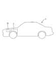
- Fig. 1 is a side view of a vehicle
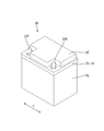
- Fig. 2 is a perspective view of a battery
- Fig. 3 is an exploded perspective view of the battery
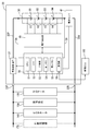
- Fig. 4 is a block diagram showing an electrical configuration of the battery.
- the automobile 1 is an engine drive vehicle having an engine 3 for driving an axle.
- the automobile 1 includes a battery 20 which is a power storage device.
- the battery 20 has a block-shaped battery case 21 as shown in FIG. 2.
- a battery pack 30 and a control board 28 consisting of a plurality of secondary batteries B1 to B4 are accommodated. ing.
- the battery case 21 has a box-shaped case body 23 opening upward, a positioning member 24 for positioning the plurality of secondary batteries B1 to B4, and a middle portion attached to the upper portion of the case body 23.
- a lid 25 and an upper lid 26 are provided.
- a plurality of cell chambers 23A in which the respective secondary batteries B1 to B4 are individually accommodated are provided side by side in the X direction.
- the positioning member 24 has a plurality of bus bars 27 disposed on the upper surface, and the positioning member 24 is disposed on the top of the plurality of secondary batteries B1 to B4 disposed in the case body 23.
- the plurality of secondary batteries B1 to B4 are positioned and connected in series by the plurality of bus bars 27.
- the inner lid 25 has a substantially rectangular shape in plan view.
- a pair of terminal portions 22P and 22N to which a harness terminal (not shown) is connected are provided at both ends of the inner lid 25 in the X direction.
- the pair of terminal portions 22P and 22N are made of, for example, a metal such as a lead alloy, 22P is a positive electrode side terminal portion, and 22N is a negative electrode side terminal portion.
- An accommodating portion 25A is provided on the upper surface of the inner lid 25.
- the control board 28 is accommodated inside the accommodation portion 25A of the inner lid 25.
- the upper lid 26 is attached to the upper portion of the inner lid 25 so as to close the upper surface of the accommodation portion 25A accommodating the control substrate 28.
- the battery 20 is for starting an engine, and includes a battery assembly 30, a current interrupting device 37, a current sensor 41, a voltage detection unit 45, and a management device 50 that manages the battery assembly 30.
- the battery assembly 30 is composed of four lithium ion secondary batteries B1 to B4 connected in series.
- the lithium ion secondary batteries B1 to B4 are examples of the "storage element" in the present invention.
- the battery assembly 30, the current sensor 41, and the current interrupting device 37 are connected in series via the current paths 35P and 35N.
- the current sensor 41 is disposed on the negative electrode conduction path 35N, and the current interrupting device 37 is disposed on the positive electrode conduction path 35P.
- the current sensor 41 is connected to the negative electrode terminal 22N, and the current interruption device 37 is connected to the positive electrode terminal 22P. It is done.
- the current sensor 41 is provided inside the battery case 21 and detects the current I flowing through the battery pack 30.
- the current sensor 41 is electrically connected to the management device 50 by a signal line, and the output of the current sensor 41 is taken into the management device 50.
- the voltage detection unit 45 is provided inside the battery case 21 and detects battery voltages V1 to V4 of the lithium ion secondary batteries B1 to B4 and a total voltage Ev of the assembled battery 30.
- the voltage detection unit 45 is electrically connected to the management device 50 by a signal line, and the output of the voltage detection unit 45 is taken into the management device 50.
- the current sensor 41 and the voltage detection unit 45 are examples of the “measurement unit” in the present invention.
- the current interrupting device 37 can be configured by a contact switch (mechanical type) such as a relay or a semiconductor switch such as an FET or a transistor.
- the current interrupting device 37 can interrupt the current by opening the positive electrode conduction path 35P.
- the management device 50 includes a CPU 51 having an arithmetic function, a ROM 52, a time measuring unit 53 for measuring time, a first memory 54, a second memory 55, a communication unit 56 and the like, and is provided on the control substrate 28.
- symbol 58 shown in FIG. 4 is a power supply line of the management apparatus 50, and the management apparatus 50 is using the assembled battery as a power supply.
- the first memory 54 corresponds to the "storage unit" of the present invention.
- the ROM 52 stores a program for executing the cause analysis flow (S10 to S60) shown in FIG.
- Various data for executing the cause analysis flow for example, thresholds X1 to X5 are stored.
- the program can be stored in a recording medium such as a CD-ROM and transferred.
- the first memory 54 is a volatile memory.
- the second memory 55 is a non-volatile memory for data backup.
- the CPU 51 monitors the current I flowing through the assembled battery 30 based on the output of the current sensor 41.
- the voltages V1 to V4 of the lithium ion secondary batteries B1 to B4 and the total voltage Ev of the assembled battery 30 are monitored based on the output of the voltage detection unit 45.
- the CPU 51 executes the cause analysis flow shown in FIG. 9 to analyze the cause of the protection operation.
- the CPU 51 corresponds to the “cause analysis unit” of the present invention.
- the communication unit 56 is provided for communication with a vehicle ECU (Electronic Control Unit) 100 mounted on the automobile 1. After mounting on the vehicle, the communication unit 56 is connected to the vehicle ECU 100 through the signal line, and the management device 50 can receive information on the vehicle such as the operation state (stop or drive) of the engine 3 from the vehicle ECU 100.
- vehicle ECU Electronic Control Unit
- the battery 20 is connected to a cell motor 130 for starting the engine, a vehicle load 150 such as each electric component mounted on the automobile 1, and an alternator 160.
- the alternator 160 is a vehicle generator that generates electric power by the power of the engine 3. When the amount of power generation of alternator 160 is larger than the power consumption of vehicle load 150 during engine operation, battery 20 is charged by alternator 160.
- the battery 20 When the power generation amount of the alternator 160 is smaller than the power consumption of the vehicle load 150, the battery 20 is discharged to compensate for the shortage. While the engine is stopped, the alternator 160 stops power generation. Therefore, battery 20 is in a state in which the power supply is stopped (a state in which it is not charged), and is in a state in which only vehicle load 150 is discharged.
- the battery 20 can be charged by connecting an external charger 170 in addition to the on-vehicle alternator 160.
- the battery 20 includes the lithium ion secondary batteries B1 to B4, the current interrupting device 37, the current sensor 41, the voltage measuring unit 45, and the management device 50, and thus corresponds to the "power storage device" of the present invention. .
- FIG. 5 is a graph showing temporal changes in the minimum voltage Vmin of the lithium ion secondary batteries B1 to B4 after the engine is stopped, with time on the horizontal axis and voltage on the vertical axis.
- the power supply from the vehicle (alternator 160) of the battery 20 is stopped, and the battery 20 is in a state of performing only discharge.
- the management device 50 is in a state of performing discharge and self discharge for the amount of consumed current. Therefore, as shown in FIG. 5, the minimum voltage Vmin of the lithium ion secondary batteries B1 to B4 decreases with the passage of time after the time ta when the engine is stopped.
- the CPU 51 of the management device 50 After stopping the engine, the CPU 51 of the management device 50 performs processing to monitor the voltages V1 to V4 of the lithium ion secondary batteries B1 to B4 (S10 in FIG. 6). Then, the CPU 51 compares the minimum voltage Vmin of the lithium ion secondary batteries B1 to B4 with the protection voltage Vb, and determines whether the minimum voltage Vmin has dropped to the protection voltage Vb. Specifically, it is determined whether the minimum voltage Vmin is smaller than the protection voltage Vb (S20).
- the protection voltage Vb is an example of the “predetermined voltage” in the present invention.
- the CPU 51 When the minimum voltage Vmin of the lithium ion secondary batteries B1 to B4 becomes smaller than the protection voltage Vb (S20: YES), the CPU 51 directly executes the protection operation (S30). Specifically, a command is given to the current interrupting device 37 to open the current path 35P, thereby interrupting the current flowing to the lithium ion secondary batteries B1 to B4. This prevents the lithium ion secondary batteries B1 to B4 from being overdischarged, that is, falling below the discharge termination voltage Vc.
- the CPU 51 of the management device 50 continues to monitor the voltages V1 to V4 and the current I of the lithium ion secondary batteries B1 to B4 even after the protection operation is performed, and the minimum voltage Vmin of the lithium ion secondary batteries B1 to B4.
- the discharge end voltage Vc is reached (S40: YES)
- the internal short circuit is a short circuit between the positive electrode and the negative electrode inside the battery.
- Overloading means that the size of the load is larger than the setting. For example, when the vehicle load 150 is added, the load becomes larger than the initial (setting).
- the long-term leaving is that the battery 20 is left for a long time with the power supply stopped. In this example, the vehicle 1 is left for a long time in a state where the external charger 170 does not charge after engine stop.
- the CPU 51 of the management device 50 performs the protection operation based on the voltages V1 to V4 and the current I of the lithium ion secondary batteries B1 to B4 after the engine stop and the data of the first period Tab and the second period Tbc. It is identified whether the cause is an internal short circuit of the battery 20, an overload of the vehicle 1, or a long-term leaving.
- the CPU 51 of the management device 50 determines whether the cause of the protection operation is an internal short circuit of the battery 20 or not according to the following judgment formula 1A and judgment formula 1B.
- the Q1ab is a first discharge capacity at which the battery 20 is discharged in a first period Tab from when the engine is stopped to when the protection operation is performed.
- the first discharge capacity Q1ab can be obtained by converting the difference between the SOC1 of the lithium ion secondary battery B at the engine stop time ta and the SOC2 of the lithium ion secondary battery B at the time tb when the protection operation is performed.
- the first period Tab corresponds to “a period from the stop of the power supply to the decrease of the storage element to a predetermined voltage” in the present invention.
- Q1ab (SOC1-SOC2) ⁇ Cbo / 100 Cbo is a full charge capacity of the battery 20.
- SOC is a ratio of the remaining capacity Cs to the full charge capacity Co of the lithium ion secondary battery B.
- the SOC can be estimated using the correlation between the open circuit voltage of the lithium ion secondary battery B and the SOC (see FIG. 7). That is, SOC1 can be estimated from open voltage Va of lithium ion secondary battery B at engine stop time ta, and SOC2 is estimated from open voltage Vb of lithium ion secondary battery B at time tb when the protection operation is performed. I can do it. For the open circuit voltages Va and Vb, it is preferable to use the lowest voltage of the open circuit voltages V1 to V4 of the lithium ion secondary batteries B1 to B4.
- the open circuit voltage is preferably the voltage V in the no-current state, but in a state where a current equal to or less than the current threshold flows (in a state where only a current at a level regarded as no current flows).
- Q2ab is a second discharge capacity in which the battery 20 is discharged to the vehicle 1, which is a load, in a first period Tab from when the engine is stopped to when the protection operation is performed.
- the second discharge capacity Q2ab is obtained by integrating the current value detected by the current sensor 41 for a first period Tab from when the engine is stopped to when the protection operation is performed.
- X1 is a capacity difference threshold value for determining whether or not the battery 20 has an internal short circuit, and the unit is ampere hour.
- Vmax_tb-Vmin_tb ⁇ X2 (1 B)
- Vmax_tb is the maximum voltage of the lithium ion secondary batteries B1 to B4 at the execution time tb of the protection operation.
- Vmin_tb is the minimum voltage of the lithium ion secondary batteries B1 to B4 at the execution time tb of the protection operation.
- X2 is a voltage difference threshold value for determining whether or not the battery 20 is internally shorted, and the unit is volt.
- the determination equation 1B uses the voltage difference, the measurement error is small, and it can be accurately determined whether the cause of execution of the protection operation is an internal short circuit of the battery 20 or not.
- the CPU 51 of the management device 50 determines whether the cause of the protection operation is overload of the vehicle 1 or not according to the following judgment formula 2.
- Iav is an average current value of the battery 20 (average value of current flowing from the battery 20 to the vehicle 1) in the first period Tab from when the engine is stopped to when the protection operation is performed.
- the average current value Iav of the battery 20 can be obtained by dividing the discharge capacity Q2ab to the vehicle by the first period Tab.
- X3 is a current threshold value for determining whether the vehicle is overloaded or not. For example, in a vehicle equipped with a standard load, the magnitude of the current I flowing from the battery 20 to the vehicle 1 while the engine is stopped is there.
- the CPU 51 of the management device 50 determines whether the cause of the protection operation is long-term leaving of the vehicle 1 or not according to the following judgment formula 3A. It is determined whether the cause of the overdischarge is long-term leaving of the vehicle or not according to the following determination formula 3B.
- Tab is an actual measurement value of the first period from the engine stop to the execution of the protection operation.
- the discharge capacity Q1ab is a capacity difference between the battery 20 when the engine is stopped and the time tb when the protective operation is performed.
- the estimated discharge current Iab is an estimated value of the current discharged by the battery 20 during the period from the engine stop to the execution of the protection operation, and as an example, the dark current of the vehicle load 150, the dark current of the management device 50, the battery It is the total value (expected value) of 20 self-discharge currents.
- the dark current is a current that the battery 20 discharges to the vehicle load 150 and the management device 50 during parking.
- Tbc is an actual measurement value of the second period from the execution of the protection operation to the overdischarge.
- the discharge capacity Q1bc of the battery 20 is the difference between the capacity of the battery 20 at the time tb of execution of the protective operation and the time tc at which overdischarge occurs.
- the estimated discharge current Ibc is an estimated value of the current discharged by the battery 20 during the period Tbc from the execution of the protective operation to the overdischarge, and as an example, the dark current of the management device 50 and the self discharge current of the battery 30 It is the total value (expected value).
- FIG. 8 shows the contents of data processing performed by the CPU 51 of the management device 50 after the engine is stopped in order to analyze the cause of the execution of the protection operation (the cause of the minimum voltage Vmin falling to the protection voltage Vb).
- the CPU 51 starts measuring the elapsed time T from the engine stop using the timer unit 53. Measurement of the current I flowing from the battery 20 to the vehicle 1 is started using the current sensor 41.
- the voltages V1 to V4 of the lithium ion secondary batteries B1 to B4 at the engine stop time ta are detected using the voltage detection unit 45. From the detected voltages V1 to V4, SOC1 of the lithium ion secondary battery B is estimated, and the result is stored in the first memory 54.
- the CPU 51 After execution of the protection operation, the CPU 51 stores, in the first memory 54, a first period Tab from when the engine is stopped to when the protection operation is performed.
- the result of integration of the current I flowing from the battery 20 to the vehicle 1 for the first period Tab is stored in the first memory 54.
- Voltage detection unit 45 detects voltages V1 to V4 of lithium ion secondary batteries B1 to B4 at time tb when the protection operation is performed, and stores maximum voltage Vmax_tb and minimum voltage Vmin_tb in first memory 54. .
- the SOC2 of the lithium ion secondary battery B is estimated from the voltages V1 to V4 of the lithium ion secondary batteries B1 to B4 at the time tb when the protection operation is performed, and the result is stored in the first memory 54.
- the CPU 51 After the detection of the overdischarge, the CPU 51 stores, in the first memory 54, a second period Tbc from the execution of the protection operation to the detection of the overdischarge.
- the above-described example data processing is reset when the management device 50 detects the start of charging by the alternator 160 or the external charger 170.
- the engine 3 of the vehicle 1 is stopped after the end of charging, data processing is started from the beginning.
- FIG. 9 is a flowchart for analyzing the cause of execution of the protection operation.
- the analysis flow of the cause is, as shown in FIG. 9, composed of S10 to S150.
- the minimum voltage Vmin of the lithium ion secondary batteries B1 to B4 falls below the discharge termination voltage Vc to detect overdischarge It is executed by the CPU 51 of the management device 50 at time tc.
- the cause analysis flow is to make the following determination based on various data obtained by the above-described data processing (see FIG. 8).
- the CPU 51 of the management device 50 determines the difference between the first discharge capacity Q1ab of the battery 20 and the second discharge capacity Q2ab for the vehicle 1 in the first period Tab, and determines the difference in discharge capacity ( Q1ab ⁇ Q2ab) is compared with the threshold value X1 (decision equation 1A).
- the CPU 51 obtains the difference between the maximum voltage Vmax_tb and the minimum voltage Vmin_tb of the lithium ion secondary batteries B1 to B4 at the execution time tb of the protection operation, and compares the obtained voltage difference Vmax_tb-Vmin_tb with the threshold X2 Determination formula 1B).
- the CPU 51 causes the protection operation to be performed. Is determined to be an internal short circuit of the battery 20.
- the CPU 51 protects the engine from stopping in S30.
- the average current value Iav flowing from the battery 20 to the vehicle 1 is compared with the threshold value X3 in the first period Tab until the operation is performed (decision formula 2).
- the CPU 51 determines that the cause of execution of the protection operation is overload.
- the CPU 51 compares the first period Tab with the threshold value X4 in S130 (determination formula 3A).
- the CPU 51 determines that the cause of the execution of the protection operation is long-term leaving.
- the CPU 51 determines in S140 whether overdischarge has been detected.
- the CPU 51 determines that the cause of the overdischarge is long-term leaving. If the second period Tbc is less than the threshold value X5 (S150: NO), it is determined that the cause is undecided.
- the CPU 51 stores (backs up) the measured data for analysis of the cause and the calculated data in the nonvolatile second memory 55 together with the specified cause. By doing this, even if the management device 50 loses power, the reason why the protection operation by the current interrupting device 37 is executed after the engine is stopped by taking out the data of the second memory 55 is that of the vehicle 1 It is possible to identify the overload, the internal short circuit of the battery 20, the long-term leaving, or the cause undetermined.
- the vehicle may be notified that the battery 20 is overdischarged and the cause of the execution of the protective operation after the engine is stopped.
- the analysis flow of the cause can be performed not only after the detection of the overdischarge but also after the execution of the protective operation after the stop of the engine and before the detection of the overdischarge.
- the CPU 51 detects the connection of the external charger 170 from the voltage change of the terminal portions 22P and 22N, The current interrupting device 37 returns from open to closed. Thereby, the battery 20 can receive the charge of the external charger 170.
- the CPU 51 can execute the analysis flow of the cause based on the data measured in the first period Tab until the protective operation is performed from the engine stop.
- NO is determined in S140, so only four determinations in S100 to S130 are performed.
- the CPU 51 of the management device 50 can communicate with the vehicle ECU 100 through the communication unit 56 after charging by the external charger 170, the CPU 51 notifies the vehicle 1 of the cause of the execution of the protection operation after the engine is stopped. If notification can not be made, the measured data is stored in the non-volatile second memory 55 for analysis of the cause together with the identified cause (analysis result).
- the supplier of the battery 20 urges the user to take an appropriate action according to the cause, such as reducing the vehicle load 150, and in the case of the internal short circuit, replacing the battery 20. I can do it. If the cause is long-term leaving, warning can be made to shorten the leaving period.
- the management device 50 analyzes the cause of the execution of the protection operation based on data measured after the engine is stopped. Therefore, even if data on running can not be acquired for the current and voltage of the lithium ion secondary batteries B1 to B4, it is possible to analyze the cause of execution of the protection operation after the engine is stopped. Furthermore, since it is not necessary to store data before the engine stop, there is an advantage that the data capacity of the first memory 54 and the second memory 55 can be reduced.
- FIG. 10 is a block diagram showing an electrical configuration of battery 200.
- the battery 200 is for starting the engine, and manages the battery assembly 30, the current interrupting device 37, the current sensor 41, the voltage detection unit 45, and the battery assembly 30. And a management device 50.
- the battery 200 has a temperature sensor 43.
- the temperature sensor 43 detects the environmental temperature of the installation place of the battery 200.
- Battery 200 is installed in a trunk room (not shown) of car 1.
- the temperature sensor 43 detects the temperature of the trunk room as the environmental temperature of the battery 200.
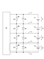
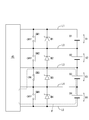
- FIG. 11 is a detailed view of voltage measurement lines of each of the lithium ion secondary batteries B1 to B4.
- the lithium ion secondary batteries B1 to B4 are connected to the voltage detection unit 45 by voltage measurement lines L1 to L5.
- Zener diodes D1 to D4 and switches SW1 to SW4 are connected in parallel with the lithium ion secondary batteries B1 to B4 between the measurement lines.
- the CPU 51 of the management device 50 switches the switches SW1 to SW4 from off to on in a predetermined order, and when the corresponding switch SW is off and the next switch is on, each lithium ion secondary battery Measure the voltage of B.
- the voltage V3 of the lithium ion secondary battery B3 is measured by detecting the voltage between the two measurement lines L3 and L4.
- the voltage V2 of the lithium ion secondary battery B2 and the voltage V1 of the lithium ion secondary battery B1 can also be measured by the same procedure.
- the CPU 51 compares the voltage measurement value of each of the lithium ion secondary batteries B1 to B4 measured by the voltage detection unit 45 as a voltage allowable range (2 to 6 V) to determine whether or not an abnormal value is included. Thus, disconnection of the voltage measurement lines L1 to L5 is detected.
- the CPU 51 After stopping the engine, the CPU 51 measures the environmental temperature using the temperature sensor 43 in addition to monitoring the voltage, current, etc. of the lithium ion secondary batteries B1 to B4, and stores the data in the first memory 54.
- the CPU 51 of the management device 50 stores the data in the first memory 54 when a disconnection is detected at the time of voltage measurement after the engine is stopped.
- FIG. 14 is a flowchart for analyzing the cause of execution of the protection operation.
- S115 and S125 are added to the analysis flow of the cause of the first embodiment (FIG. 9).
- S115 is processing to determine whether a break in the voltage measurement line L has been detected after the engine has stopped.
- the CPU 51 of the management device 50 can determine the presence or absence of the disconnection by accessing the first memory 54.
- the measurement value of the voltage detection unit 45 may be a voltage lower than the normal value. Therefore, it can be determined that the cause of the execution of the protection operation is a break.
- the CPU 51 When the protection operation is performed after the engine is stopped, the CPU 51 performs the determinations of S100, S110, and S115, and when the determination is YES in any of them, the cause of the execution of the protection operation is battery 200 such as internal short circuit or disconnection. It is determined that the defect is
- S125 is processing to determine whether the average value of the environmental temperature of the battery 200 is X6 or more for the first period Tab from when the engine is stopped to when the protection operation is performed.
- X6 is a temperature threshold for determining whether the environmental temperature of the battery is appropriate. When the environmental temperature is high, the reaction speed inside the battery is increased, and the self-discharge amount of the lithium ion secondary battery is increased. When the average value of the environmental temperature is equal to or higher than the threshold value X6, it can be determined that the cause of the execution of the protection operation is use in a high temperature environment.
- the CPU 51 performs the processing of S120, S125, and S130, and if YES is determined in any of them, the cause of execution of the protection operation is overload, It is determined that the use of the battery 50 (usage mode) such as use in a high temperature environment, long-term storage, etc.
- the second embodiment it is possible to determine whether the cause of execution of the protection operation after the engine stop is a defect of the battery 200 or how the battery 200 is used.
- FIG. 15 is a block diagram of an electric vehicle 300.
- the electric vehicle 300 includes a drive motor 310, an on-vehicle charger 330 chargeable from a commercial power source, a drive battery 350, an inverter 360, a DC / DC converter 370, and an accessory battery 380. .
- Driving battery 350 is rated at 100 V to 400 V and can be charged by on-vehicle charger 200.
- the drive battery 350 is connected to a drive motor 310 which is a main load via an inverter 360.
- the inverter 360 converts the power of the drive battery 350 from direct current to alternating current and supplies the drive motor 3100 with the power.
- the drive motor 310 is for driving the electric vehicle 300, and drives an axle 320 mounted with wheels 325.
- Auxiliary battery 380 has a rating of 12 V, and is connected to vehicle charger 330 via DC / DC converter 370.
- the DC / DC converter 3700 steps down the output voltage of the on-vehicle charger 200 to supply power to the accessory battery 380, thereby charging the accessory battery 380.
- the electric vehicle 300 has a power supply connection 400.
- the power supply connection unit 400 is branched and connected to a power line 365 connecting the inverter 360 and the drive motor 310.
- a plug (not shown) to the power supply connection unit 400, the drive battery 350 can be used as an emergency power supply for disasters and the like.
- the drive battery 350 may be used in an overload state such as an emergency power supply, and the voltage of the drive battery 350 may decrease even while the drive motor 310 serving as the main load is not running. .
- the drive battery 350 can determine the operation state of the drive motor 310 which is the main load by communication with the vehicle ECU mounted on the electric vehicle 300.
- the driving battery 350 can determine the presence or absence of charging from the measurement value of the built-in current sensor.
- the present invention is applied to the drive battery 350, and after charging is stopped, data of the voltage, current, elapsed time, and environmental temperature of the drive battery 350 are measured for the stop period of the drive motor 310 which is the main load.
- the protection device operates during the stop period of the drive motor 310, the measured data is post-analyzed to determine the cause.
- the lithium ion secondary battery B is illustrated as an example of the storage element.
- the storage element is not limited to the lithium ion secondary battery B, and may be another secondary battery. It may be a capacitor or the like.
- Embodiment 1 although the form which connected multiple lithium ion secondary batteries B in series was illustrated, you may be a structure of a single cell.
- the application of the battery 20 is for engine start, but may be for other applications such as auxiliary equipment. If it is an application used as a power supply in a state where the power supply to the battery 20 is stopped (charging stop state), the present invention can also be applied to applications other than for vehicles, such as an electric power tool or a computer power supply.
- the measurement data for analyzing the cause of the low voltage abnormality may be in operation after the charge is stopped.
- Embodiments 1 and 2 illustrated the configuration in which the current interrupting device 37 and the management device 50 are provided inside the battery 20.
- the current interrupting device 37 and the management device 50 do not necessarily have to be installed inside the battery 20, and may be provided outside the battery 20 as long as they are mounted on the vehicle. That is, the battery 20 may be configured only with a storage element and sensors that measure voltage and current, and the current interrupting device 37 provided outside the battery may perform a protection operation.
- the management device 50 provided outside the battery may execute a process of analyzing the cause of the execution of the protection operation by monitoring the output from the sensor.
- the determination as to whether or not to perform the protection operation may be made based on the total voltage Ev of the assembled battery 30, not limited to the one based on the minimum voltage Vmin of the storage elements B1 to B4.
- the determination of the overdischarge is also the same.
- the minimum voltage Vmin of the storage elements B1 to B4 decreases to the protection voltage Vb after the engine stops, based on the measurement data of the storage elements B1 to B4 measured after the engine stops.
- To analyze its cause when the physical quantity (for example, the SOC of the storage element and the remaining capacity) highly correlated with the voltage decreases to a predetermined value (the SOC value and the remaining capacity value corresponding to the protection voltage Vb)
- the cause may be analyzed based on the measured data of the storage elements B1 to B4 measured.
- the SOC can be calculated by a current integration method which integrates charge / discharge current of the storage element, or an OCV method using the correlation of OCV-SOC.
- the remaining capacity can be calculated from the SOC of the storage element and the full charge capacity of the storage element.
- the CPU 51 of the management device 50 determines whether the minimum voltage Vmin of the storage elements B1 to B4 has dropped to the protection voltage Vb.
- the subject of the determination is not limited to the management device 50.
- the above-mentioned judgment is performed by a control device higher than the battery 50 such as the vehicle ECU 100, and the result is input to the management device 50, and the management device 50 correlates with the cause or voltage The cause of the decrease in physical quantity may be analyzed.
- the vehicle ECU 100 monitors the voltage V and current I of the storage elements B1 to B4 based on the outputs from sensors provided inside the battery 20. After the engine is stopped, the vehicle ECU 100 stores electricity. It is determined whether the minimum voltage Vmin of the elements B1 to B4 has dropped to the protection voltage Vb. Similar to the vehicle ECU 100, the management device 50 is mounted on the vehicle and disposed outside the battery. When it is determined that the minimum voltage Vmin of the storage elements B1 to B4 has decreased to the protection voltage Vb, the vehicle ECU 100 performs an input for conveying the above determination to the management device 50. If there is an input to convey the above determination, the management device 50 analyzes the cause based on the measurement data of the storage elements B1 to B4 measured after the engine is stopped.
- the first and second embodiments analyze the cause of execution of the protection operation by the current interrupting device 37, that is, the cause of reduction of the minimum voltage Vmin of the storage elements B1 to B4 to the protection voltage Vb.
- the present invention can be widely applied as long as it analyzes the cause of the storage element decreasing to a predetermined voltage. For example, it may be possible to analyze the cause of the storage element being lowered to the lower limit voltage of the use range or the discharge end voltage.
- internal short circuit (S100, S110), overload (S120), and long-term leaving (S130, S140) are determined as the cause of execution of the protection operation.
- disconnection (S115) and the environmental temperature (S125) are determined in addition to the internal short circuit (S100, S110), the overload (S120), and the long-term leaving (S130, S140). It is not necessary to determine all of the five items of internal short circuit, overload, long-term leaving, disconnection, and environmental temperature as causes for execution of the protection operation, and it may be determined only a part.
- the measurement data to be measured after stopping the engine may include at least one of the current of the storage element, the environmental temperature of the storage element, and the elapsed time, in addition to the voltage of the storage element.
- two judgment formulas 1A and 1B are used to judge whether the cause of execution of the protection operation by the current interrupting device is an internal short circuit of the battery or not. The determination may be made using only one of the determination formulas.
- the CPU 51 determines whether the cause of the execution of the protection operation is a defect of the battery 200 based on the determination results of S100, S110, and S115. Then, it is determined from the determination results of S120, 125, and 130 whether or not the battery 200 is used. S100, S110, and S115 may be omitted, and the CPU 51 performs only the determination of S120, S125, and S130 if the protection operation is performed after the engine is stopped, and if any of the determination results in YES, the protection operation is performed.
- the cause is the use of the battery 200, and if all the determinations are NO, it may be determined that the cause of the execution of the protection operation is not the use of the battery 200.
- S120, S125, and S130 may be omitted, and the CPU 51 performs only the determination of S100, S110, and S115 if the protection operation is performed after the engine is stopped, and if any of the determination results in YES, the protection operation is performed.
- the cause may be determined as a defect of the battery 200, and when all the determinations are NO, it may be determined that the cause of the execution of the protection operation is not a defect of the battery 200.
- the techniques disclosed in the first to third embodiments can be realized in various modes such as an analysis program for analyzing the cause of the decrease in voltage of the storage element, and a recording medium recording such a program.
- a program for analyzing a cause of a drop in a voltage of a storage element or a cause of a drop in a physical quantity having a correlation with a voltage wherein the power storage element has dropped to a predetermined voltage after the supply of power to the storage element is stopped
- the cause of the voltage drop of the storage element or the correlation with the voltage is based on the measurement data of the storage element measured after stopping the power supply
- a cause analysis program that causes a computer to execute cause analysis processing (S100 to S150 or S100 to S130) that analyzes the cause of a decrease in physical quantity to the predetermined value.
Landscapes
- Engineering & Computer Science (AREA)
- Manufacturing & Machinery (AREA)
- Chemical & Material Sciences (AREA)
- Chemical Kinetics & Catalysis (AREA)
- Electrochemistry (AREA)
- General Chemical & Material Sciences (AREA)
- Physics & Mathematics (AREA)
- General Physics & Mathematics (AREA)
- Power Engineering (AREA)
- Secondary Cells (AREA)
- Tests Of Electric Status Of Batteries (AREA)
- Charge And Discharge Circuits For Batteries Or The Like (AREA)
Abstract
L'invention concerne un dispositif de gestion 50 pour des éléments de stockage d'énergie comprenant une unité d'analyse de cause 51 qui, lorsque les tensions des éléments de stockage d'énergie B1-B4 sont réduites à un niveau prescrit ou des quantités physiques corrélées aux tensions sont réduites à des valeurs prescrites après que l'alimentation en énergie des éléments de stockage d'énergie B1-B4 a été arrêtée, analyse la cause de la réduction de tension dans les éléments de stockage d'énergie B1-B4 ou la cause de la réduction des quantités physiques corrélées avec des tensions aux valeurs prescrites, sur la base de données de mesure des éléments de stockage d'énergie B1-B4 mesurées après l'arrêt de l'alimentation de puissance.
Priority Applications (4)
| Application Number | Priority Date | Filing Date | Title |
|---|---|---|---|
| CN201880068922.2A CN111263999A (zh) | 2017-11-02 | 2018-11-02 | 管理装置、蓄电装置、原因的解析方法、发动机驱动车、电动汽车 |
| DE112018005187.0T DE112018005187T5 (de) | 2017-11-02 | 2018-11-02 | Verwaltungsvorrichtung, Energiespeicherapparatur, Ursachenanalyseverfahren, motorgetriebenes Fahrzeug und Elektrofahrzeug |
| US16/758,356 US11581589B2 (en) | 2017-11-02 | 2018-11-02 | Management device, energy storage apparatus, cause analysis method, engine-driven vehicle, and electric vehicle |
| JP2019550503A JP6977779B2 (ja) | 2017-11-02 | 2018-11-02 | 管理装置、蓄電装置、原因の解析方法、エンジン駆動車、電気自動車 |
Applications Claiming Priority (2)
| Application Number | Priority Date | Filing Date | Title |
|---|---|---|---|
| JP2017-212664 | 2017-11-02 | ||
| JP2017212664 | 2017-11-02 |
Publications (1)
| Publication Number | Publication Date |
|---|---|
| WO2019088264A1 true WO2019088264A1 (fr) | 2019-05-09 |
Family
ID=66333266
Family Applications (1)
| Application Number | Title | Priority Date | Filing Date |
|---|---|---|---|
| PCT/JP2018/040888 WO2019088264A1 (fr) | 2017-11-02 | 2018-11-02 | Dispositif de gestion, dispositif de stockage d'énergie, procédé d'analyse des causes, véhicule entraîné par moteur et automobile électrique |
Country Status (5)
| Country | Link |
|---|---|
| US (1) | US11581589B2 (fr) |
| JP (1) | JP6977779B2 (fr) |
| CN (1) | CN111263999A (fr) |
| DE (1) | DE112018005187T5 (fr) |
| WO (1) | WO2019088264A1 (fr) |
Cited By (1)
| Publication number | Priority date | Publication date | Assignee | Title |
|---|---|---|---|---|
| WO2020196366A1 (fr) * | 2019-03-27 | 2020-10-01 | 株式会社Gsユアサ | Dispositif de stockage électrique, et procédé et programme d'estimation de capacité d'élément de stockage électrique |
Citations (5)
| Publication number | Priority date | Publication date | Assignee | Title |
|---|---|---|---|---|
| JP2000028690A (ja) * | 1998-07-13 | 2000-01-28 | Mitsubishi Chemicals Corp | 二次電池の短絡検査方法および当該検査方法を包含する二次電池の製造方法 |
| JP2009096417A (ja) * | 2007-10-19 | 2009-05-07 | Panasonic Corp | バッテリ状態表示システム |
| JP2010181262A (ja) * | 2009-02-05 | 2010-08-19 | Sanyo Electric Co Ltd | 二次電池の異常検出装置および二次電池装置 |
| JP2013074708A (ja) * | 2011-09-27 | 2013-04-22 | Sanyo Electric Co Ltd | 車両用の電源装置とこの電源装置を備える車両 |
| JP2013219984A (ja) * | 2012-04-11 | 2013-10-24 | Toyota Motor Corp | バッテリ充電制御装置 |
Family Cites Families (8)
| Publication number | Priority date | Publication date | Assignee | Title |
|---|---|---|---|---|
| JP2009170397A (ja) * | 2007-12-18 | 2009-07-30 | Mitsumi Electric Co Ltd | 電池パック、電池パックを用いる携帯機器、電池パックにおける内部ショート検出方法、内部ショート検出プログラム |
| JP5520580B2 (ja) * | 2009-11-25 | 2014-06-11 | 古河電気工業株式会社 | 蓄電池のセル短絡検知方法及び検知装置 |
| JP2011142036A (ja) | 2010-01-08 | 2011-07-21 | Sanyo Electric Co Ltd | 電池管理方法および電子機器 |
| JP5662105B2 (ja) | 2010-10-26 | 2015-01-28 | 株式会社マキタ | 二次電池パック |
| JP2013242324A (ja) | 2013-07-11 | 2013-12-05 | Mitsubishi Motors Corp | 電池監視装置 |
| JP6090093B2 (ja) | 2013-10-02 | 2017-03-08 | トヨタ自動車株式会社 | 二次電池の検査方法及び検査装置 |
| JP2016090399A (ja) * | 2014-11-05 | 2016-05-23 | 日本電信電話株式会社 | 短絡検出方法、短絡検出システムおよび短絡電流値算出方法 |
| JP6316397B1 (ja) * | 2016-12-26 | 2018-04-25 | 三菱電機株式会社 | 電力変換システム |
-
2018
- 2018-11-02 CN CN201880068922.2A patent/CN111263999A/zh active Pending
- 2018-11-02 US US16/758,356 patent/US11581589B2/en active Active
- 2018-11-02 JP JP2019550503A patent/JP6977779B2/ja active Active
- 2018-11-02 DE DE112018005187.0T patent/DE112018005187T5/de active Pending
- 2018-11-02 WO PCT/JP2018/040888 patent/WO2019088264A1/fr active Application Filing
Patent Citations (5)
| Publication number | Priority date | Publication date | Assignee | Title |
|---|---|---|---|---|
| JP2000028690A (ja) * | 1998-07-13 | 2000-01-28 | Mitsubishi Chemicals Corp | 二次電池の短絡検査方法および当該検査方法を包含する二次電池の製造方法 |
| JP2009096417A (ja) * | 2007-10-19 | 2009-05-07 | Panasonic Corp | バッテリ状態表示システム |
| JP2010181262A (ja) * | 2009-02-05 | 2010-08-19 | Sanyo Electric Co Ltd | 二次電池の異常検出装置および二次電池装置 |
| JP2013074708A (ja) * | 2011-09-27 | 2013-04-22 | Sanyo Electric Co Ltd | 車両用の電源装置とこの電源装置を備える車両 |
| JP2013219984A (ja) * | 2012-04-11 | 2013-10-24 | Toyota Motor Corp | バッテリ充電制御装置 |
Cited By (1)
| Publication number | Priority date | Publication date | Assignee | Title |
|---|---|---|---|---|
| WO2020196366A1 (fr) * | 2019-03-27 | 2020-10-01 | 株式会社Gsユアサ | Dispositif de stockage électrique, et procédé et programme d'estimation de capacité d'élément de stockage électrique |
Also Published As
| Publication number | Publication date |
|---|---|
| US20200343598A1 (en) | 2020-10-29 |
| CN111263999A (zh) | 2020-06-09 |
| JP6977779B2 (ja) | 2021-12-08 |
| DE112018005187T5 (de) | 2020-07-23 |
| JPWO2019088264A1 (ja) | 2020-11-26 |
| US11581589B2 (en) | 2023-02-14 |
Similar Documents
| Publication | Publication Date | Title |
|---|---|---|
| US7649338B2 (en) | Method for compensating state of charge of battery and battery management system using the same | |
| US20140084867A1 (en) | Secondary battery device and battery capacity estimation system | |
| US8159186B2 (en) | Power source system, power supply control method for the power source system, power supply control program for the power source system, and computer-readable recording medium with the power supply control program recorded thereon | |
| US9800066B2 (en) | Electricity distribution device, and controlling method for battery pack | |
| EP2846395A2 (fr) | Bloc batterie, appareil comprenant un tel bloc et procédé de gestion associé | |
| US20140021923A1 (en) | Electrical storage system, and control method for electrical storage system | |
| JP7145865B2 (ja) | 充電可能電池短絡予測装置および充電可能電池短絡予測方法 | |
| KR101746139B1 (ko) | 보조 배터리를 이용한 셀 밸런싱 장치 및 방법 | |
| KR20020064998A (ko) | 배터리 성능 측정 시스템 및 측정방법 | |
| KR20090023547A (ko) | 전지 팩의 이상 판정 방법 및 전지 팩 | |
| EP3605127A1 (fr) | Dispositif et procédé d'estimation de résistance de batterie | |
| JP7067549B2 (ja) | 蓄電素子管理装置及び蓄電素子管理方法 | |
| US11381095B2 (en) | Management device, energy storage apparatus, and management method for energy storage device | |
| CN110679052B (zh) | 蓄电元件的保护装置 | |
| WO2019208410A1 (fr) | Procédé de diagnostic de défaillance et dispositif de gestion pour élément de stockage d'électricité | |
| KR101561887B1 (ko) | 차등적 soc 추정의 배터리 관리 장치와 방법 및 배터리 팩 | |
| JP7207817B2 (ja) | バッテリー管理方法、バッテリー装置、およびバッテリーを含む自動車 | |
| CN114188618A (zh) | 用于求取电池系统的充电状态的方法、电池系统 | |
| CN112384405B (zh) | 控制车辆中的电池系统的方法 | |
| WO2019088264A1 (fr) | Dispositif de gestion, dispositif de stockage d'énergie, procédé d'analyse des causes, véhicule entraîné par moteur et automobile électrique | |
| CN110875622B (zh) | 恢复深度放电的电池模块的方法及所属的不间断供电系统 | |
| JP2003217686A (ja) | バッテリーの状態値を把握する方法 | |
| US10333182B2 (en) | Estimation of cell voltage excursion in the presence of battery pack sensing faults | |
| KR20220167847A (ko) | 배터리 관리 시스템, 배터리 팩, 전기 차량 및 배터리 관리 방법 | |
| JP6969307B2 (ja) | 管理装置、蓄電システム、蓄電素子の残存容量を均等化する方法、蓄電素子の内部状態を推定する方法 |
Legal Events
| Date | Code | Title | Description |
|---|---|---|---|
| 121 | Ep: the epo has been informed by wipo that ep was designated in this application |
Ref document number: 18873635 Country of ref document: EP Kind code of ref document: A1 |
|
| ENP | Entry into the national phase |
Ref document number: 2019550503 Country of ref document: JP Kind code of ref document: A |
|
| 122 | Ep: pct application non-entry in european phase |
Ref document number: 18873635 Country of ref document: EP Kind code of ref document: A1 |