WO2019088244A1 - シフトレンジ制御装置 - Google Patents
シフトレンジ制御装置 Download PDFInfo
- Publication number
- WO2019088244A1 WO2019088244A1 PCT/JP2018/040799 JP2018040799W WO2019088244A1 WO 2019088244 A1 WO2019088244 A1 WO 2019088244A1 JP 2018040799 W JP2018040799 W JP 2018040799W WO 2019088244 A1 WO2019088244 A1 WO 2019088244A1
- Authority
- WO
- WIPO (PCT)
- Prior art keywords
- motor
- rotation angle
- pattern
- shift range
- phase
- Prior art date
- Legal status (The legal status is an assumption and is not a legal conclusion. Google has not performed a legal analysis and makes no representation as to the accuracy of the status listed.)
- Ceased
Links
Images


Classifications
-
- H—ELECTRICITY
- H02—GENERATION; CONVERSION OR DISTRIBUTION OF ELECTRIC POWER
- H02P—CONTROL OR REGULATION OF ELECTRIC MOTORS, ELECTRIC GENERATORS OR DYNAMO-ELECTRIC CONVERTERS; CONTROLLING TRANSFORMERS, REACTORS OR CHOKE COILS
- H02P6/00—Arrangements for controlling synchronous motors or other dynamo-electric motors using electronic commutation dependent on the rotor position; Electronic commutators therefor
- H02P6/14—Electronic commutators
- H02P6/16—Circuit arrangements for detecting position
-
- F—MECHANICAL ENGINEERING; LIGHTING; HEATING; WEAPONS; BLASTING
- F16—ENGINEERING ELEMENTS AND UNITS; GENERAL MEASURES FOR PRODUCING AND MAINTAINING EFFECTIVE FUNCTIONING OF MACHINES OR INSTALLATIONS; THERMAL INSULATION IN GENERAL
- F16H—GEARING
- F16H61/00—Control functions within control units of change-speed- or reversing-gearings for conveying rotary motion ; Control of exclusively fluid gearing, friction gearing, gearings with endless flexible members or other particular types of gearing
- F16H61/26—Generation or transmission of movements for final actuating mechanisms
- F16H61/28—Generation or transmission of movements for final actuating mechanisms with at least one movement of the final actuating mechanism being caused by a non-mechanical force, e.g. power-assisted
- F16H61/32—Electric motors , actuators or related electrical control means therefor
-
- F—MECHANICAL ENGINEERING; LIGHTING; HEATING; WEAPONS; BLASTING
- F16—ENGINEERING ELEMENTS AND UNITS; GENERAL MEASURES FOR PRODUCING AND MAINTAINING EFFECTIVE FUNCTIONING OF MACHINES OR INSTALLATIONS; THERMAL INSULATION IN GENERAL
- F16H—GEARING
- F16H61/00—Control functions within control units of change-speed- or reversing-gearings for conveying rotary motion ; Control of exclusively fluid gearing, friction gearing, gearings with endless flexible members or other particular types of gearing
- F16H61/12—Detecting malfunction or potential malfunction, e.g. fail safe ; Circumventing or fixing failures
-
- H—ELECTRICITY
- H02—GENERATION; CONVERSION OR DISTRIBUTION OF ELECTRIC POWER
- H02P—CONTROL OR REGULATION OF ELECTRIC MOTORS, ELECTRIC GENERATORS OR DYNAMO-ELECTRIC CONVERTERS; CONTROLLING TRANSFORMERS, REACTORS OR CHOKE COILS
- H02P29/00—Arrangements for regulating or controlling electric motors, appropriate for both AC and DC motors
- H02P29/02—Providing protection against overload without automatic interruption of supply
- H02P29/024—Detecting a fault condition, e.g. short circuit, locked rotor, open circuit or loss of load
- H02P29/028—Detecting a fault condition, e.g. short circuit, locked rotor, open circuit or loss of load the motor continuing operation despite the fault condition, e.g. eliminating, compensating for or remedying the fault
-
- H—ELECTRICITY
- H02—GENERATION; CONVERSION OR DISTRIBUTION OF ELECTRIC POWER
- H02P—CONTROL OR REGULATION OF ELECTRIC MOTORS, ELECTRIC GENERATORS OR DYNAMO-ELECTRIC CONVERTERS; CONTROLLING TRANSFORMERS, REACTORS OR CHOKE COILS
- H02P6/00—Arrangements for controlling synchronous motors or other dynamo-electric motors using electronic commutation dependent on the rotor position; Electronic commutators therefor
- H02P6/12—Monitoring commutation; Providing indication of commutation failure
-
- F—MECHANICAL ENGINEERING; LIGHTING; HEATING; WEAPONS; BLASTING
- F16—ENGINEERING ELEMENTS AND UNITS; GENERAL MEASURES FOR PRODUCING AND MAINTAINING EFFECTIVE FUNCTIONING OF MACHINES OR INSTALLATIONS; THERMAL INSULATION IN GENERAL
- F16H—GEARING
- F16H61/00—Control functions within control units of change-speed- or reversing-gearings for conveying rotary motion ; Control of exclusively fluid gearing, friction gearing, gearings with endless flexible members or other particular types of gearing
- F16H61/12—Detecting malfunction or potential malfunction, e.g. fail safe ; Circumventing or fixing failures
- F16H2061/1256—Detecting malfunction or potential malfunction, e.g. fail safe ; Circumventing or fixing failures characterised by the parts or units where malfunctioning was assumed or detected
- F16H2061/1288—Detecting malfunction or potential malfunction, e.g. fail safe ; Circumventing or fixing failures characterised by the parts or units where malfunctioning was assumed or detected the failing part is an actuator
-
- F—MECHANICAL ENGINEERING; LIGHTING; HEATING; WEAPONS; BLASTING
- F16—ENGINEERING ELEMENTS AND UNITS; GENERAL MEASURES FOR PRODUCING AND MAINTAINING EFFECTIVE FUNCTIONING OF MACHINES OR INSTALLATIONS; THERMAL INSULATION IN GENERAL
- F16H—GEARING
- F16H61/00—Control functions within control units of change-speed- or reversing-gearings for conveying rotary motion ; Control of exclusively fluid gearing, friction gearing, gearings with endless flexible members or other particular types of gearing
- F16H61/26—Generation or transmission of movements for final actuating mechanisms
- F16H61/28—Generation or transmission of movements for final actuating mechanisms with at least one movement of the final actuating mechanism being caused by a non-mechanical force, e.g. power-assisted
- F16H61/32—Electric motors , actuators or related electrical control means therefor
- F16H2061/326—Actuators for range selection, i.e. actuators for controlling the range selector or the manual range valve in the transmission
Definitions
- the present invention relates to a shift range control device.
- An object of the present disclosure is to provide a shift range control device capable of appropriately switching a shift range even when an abnormality occurs in a signal from a rotation angle sensor.
- the shift range control device of the present disclosure controls switching of the shift range by controlling driving of a motor, and includes a signal acquisition unit and a drive control unit.
- the signal acquisition unit acquires a rotation angle signal from a rotation angle sensor capable of outputting rotation angle signals of three or more phases different in phase.
- the drive control unit controls the drive of the motor such that the rotational position of the motor becomes the target rotational position according to the target shift range.
- the drive control unit changes the energization pattern from the normal time, and continues driving of the motor.
- a rotation angle sensor one capable of outputting rotation angle signals of three or more phases is used, and even if an abnormality occurs in one phase, it will be correctly energized if it jumps with momentum. Therefore, when abnormality occurs in the rotation angle sensor, the drive pattern can be changed from normal and the inertia can be used to appropriately continue the driving of the motor. Therefore, the shift range can be appropriately switched. it can.
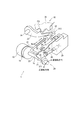
- FIG. 1 is a perspective view of a shift-by-wire system according to a first embodiment
- FIG. 2 is a schematic block diagram showing a shift-by-wire system according to the first embodiment
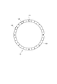
- FIG. 3 is a schematic view for explaining the arrangement of Hall ICs of the encoder according to the first embodiment
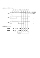
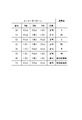
- FIG. 4A is an explanatory view for explaining an encoder pattern and an energization phase according to an electrical angle according to the first embodiment
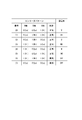
- FIG. 4B is an explanatory view for explaining a conducting phase according to the encoder pattern according to the first embodiment
- FIG. 1 is a perspective view of a shift-by-wire system according to a first embodiment
- FIG. 2 is a schematic block diagram showing a shift-by-wire system according to the first embodiment
- FIG. 3 is a schematic view for explaining the arrangement of Hall ICs of the encoder according to the first embodiment
- FIG. 4A is an explanatory view for explaining an encoder pattern and an energization phase according to an electrical angle according to the first
- FIG. 5 is a flowchart illustrating encoder interrupt processing according to the first embodiment
- FIG. 6 is a flowchart illustrating drive control processing according to the first embodiment
- FIG. 7 is a flowchart illustrating open drive request determination processing according to the first embodiment
- FIG. 8 is a time chart explaining the motor drive processing according to the first embodiment
- FIG. 9 is a time chart explaining the motor drive processing according to the first embodiment
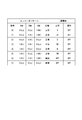
- FIG. 10A is an explanatory view for explaining an encoder pattern and an energization phase according to an electrical angle according to a second embodiment
- FIG. 10B is an explanatory view for explaining the energized phase according to the encoder pattern according to the second embodiment
- FIG. 11A is an explanatory view for explaining an encoder pattern and an energization phase according to an electrical angle according to a third embodiment, It is an explanatory view explaining the energization phase according to the encoder pattern by a 3rd embodiment
- FIG. 12 is a flowchart illustrating encoder interrupt processing according to the third embodiment
- FIG. 13 is a flowchart illustrating encoder interrupt processing according to the fourth embodiment
- FIG. 14 is a flowchart illustrating drive control processing according to the fourth embodiment
- FIG. 15 is a time chart explaining motor drive processing according to the fourth embodiment
- FIG. 16 is a time chart explaining motor drive processing according to the fourth embodiment.
- FIGS. 1 and 2 A shift range control device according to a first embodiment is shown in FIGS.
- the shift-by-wire system 1 includes a motor 10, a shift range switching mechanism 20, a parking lock mechanism 30, a shift range control device 40, and the like.
- the motor 10 is rotated by being supplied with electric power from a battery mounted on a vehicle (not shown), and functions as a drive source of the shift range switching mechanism 20.
- the motor 10 of the present embodiment is a switched reluctance motor, any type of motor such as a DC motor may be used.
- the encoder 13 detects the rotational position of a not-shown rotor of the motor 10 and outputs a rotational angle signal according to the electrical angle.
- the encoder 13 is, for example, a magnetic rotary encoder, and is a three-phase encoder having a magnet plate 135 that rotates integrally with the rotor, and Hall ICs 131, 132, and 133 for detecting magnetism.
- the Hall ICs 131 to 133 have Hall elements that output a voltage according to the direction and magnitude of the magnetic field, and output to the shift range control device 40 a signal obtained by converting the analog signal of the Hall element into a digital signal. . As shown in FIG.
- the Hall ICs 131 to 133 are arranged such that the phase of the rotation angle signal is shifted by 120 ° in electrical angle.
- the rotation angle signal output from the Hall IC 131 is referred to as an A phase signal
- the rotation angle signal output from the Hall IC 132 as a B phase signal
- the rotation angle signal output from the Hall IC 133 as a C phase signal.
- the reduction gear 14 is provided between the motor shaft 105 of the motor 10 and the output shaft 15, and decelerates the rotation of the motor 10 and outputs it to the output shaft 15. Thus, the rotation of the motor 10 is transmitted to the shift range switching mechanism 20.
- the output shaft 15 is provided with an output shaft sensor 16 that detects the angle of the output shaft 15.
- the output shaft sensor 16 is, for example, a potentiometer.
- the shift range switching mechanism 20 has a detent plate 21 and a detent spring 25 and the like, and the rotational driving force output from the reduction gear 14 is a manual valve 28 and a parking lock mechanism 30. Transmit to
- the detent plate 21 is fixed to the output shaft 15 and driven by the motor 10.
- the direction in which the detent plate 21 separates from the base of the detent spring 25 is the forward rotation direction
- the direction in which the detent plate 21 approaches the base is the reverse rotation direction.
- the detent plate 21 is provided with a pin 24 projecting in parallel with the output shaft 15.
- the pin 24 is connected to the manual valve 28.
- the shift range switching mechanism 20 converts the rotational movement of the motor 10 into a linear movement and transmits it to the manual valve 28.
- the manual valve 28 is provided on the valve body 29. The manual valve 28 reciprocates in the axial direction, thereby switching the hydraulic pressure supply path to the hydraulic clutch (not shown), and switching the engagement state of the hydraulic clutch changes the shift range.
- Two recesses 22 and 23 are provided on the detent spring 25 side of the detent plate 21.
- the side closer to the base of the detent spring 25 is referred to as the recess 22, and the side farther from the base is referred to as the recess 23.
- the recess 22 corresponds to the NotP range other than the P range
- the recess 23 corresponds to the P range.
- the detent spring 25 is an elastically deformable plate-like member, and the detent roller 26 is provided at the tip.
- the detent spring 25 biases the detent roller 26 toward the rotation center of the detent plate 21.
- the detent spring 25 elastically deforms, and the detent roller 26 moves in the recessed portions 22 and 23.
- the detent roller 26 By the detent roller 26 being fitted in either of the recessed portions 22 and 23, the swing of the detent plate 21 is restricted, the axial position of the manual valve 28 and the state of the parking lock mechanism 30 are determined, and automatic shifting is performed.
- the shift range of machine 5 is fixed.
- the detent roller 26 fits into the recess 22 when the shift range is the NotP range, and fits into the recess 23 when the shift range is the P range.
- the parking lock mechanism 30 has a parking rod 31, a cone 32, a parking lock pole 33, a shaft 34 and a parking gear 35.
- the parking rod 31 is formed in a substantially L-shape, and one end 311 side is fixed to the detent plate 21.
- a conical body 32 is provided on the other end 312 side of the parking rod 31.
- the conical body 32 is formed to decrease in diameter toward the other end 312 side.
- the parking gear 35 is provided on an axle (not shown), and is provided so as to be able to mesh with the convex portion 331 of the parking lock pole 33.
- the rotation of the axle is restricted.
- the shift range is the NotP range
- the parking gear 35 is not locked by the parking lock pole 33, and the rotation of the axle is not blocked by the parking lock mechanism 30.
- the shift range is the P range
- the parking gear 35 is locked by the parking lock pole 33, and the rotation of the axle is restricted.
- the shift range control device 40 has a motor driver 41, an ECU 50, and the like.
- the motor driver 41 switches energization to each phase (U phase, V phase, W phase) of the motor 10.
- a motor relay 46 is provided between the motor driver 41 and the battery. The motor relay 46 is turned on when the start switch of the vehicle such as an ignition switch is turned on, and power is supplied to the motor 10 side. Further, the motor relay 46 is turned off when the start switch is turned off, and the power supply to the motor 10 side is cut off.
- the ECU 50 is mainly composed of a microcomputer and the like, and includes a CPU, a ROM, a RAM, an I / O, and a bus line connecting these components, which are not shown.
- Each process in the ECU 50 may be a software process by executing a program stored in advance in a tangible memory device (that is, a readable non-transitory tangible recording medium) such as a ROM by a CPU, or may be dedicated It may be hardware processing by an electronic circuit.
- the ECU 50 controls the switching of the shift range by controlling the drive of the motor 10 based on the shift signal corresponding to the driver request shift range, the signal from the brake switch, the vehicle speed, and the like. Further, the ECU 50 controls the driving of the shift hydraulic control solenoid 6 based on the vehicle speed, the accelerator opening degree, the driver's requested shift range, and the like. By controlling the shift hydraulic control solenoid 6, the gear is controlled.
- the transmission hydraulic control solenoid 6 is provided in a number corresponding to the number of shift stages and the like. In the present embodiment, one ECU 50 controls the drive of the motor 10 and the solenoid 6, but the motor control ECU for controlling the motor 10 may be divided into an AT-ECU for solenoid control. Hereinafter, drive control of the motor 10 will be mainly described.
- the ECU 50 has a signal acquisition unit 51, an abnormality monitoring unit 52, and a drive control unit 55.
- the signal acquisition unit 51 acquires the rotation angle signal from the encoder 13 and the signal from the output shaft sensor 16.
- the signal acquisition unit 51 reads an encoder pattern for each pulse edge interruption of the rotation angle signal from the encoder 13.
- the signal acquisition unit 51 counts up or down the encoder count value ⁇ en according to the signal pattern for each encoder pulse edge.
- the encoder count value ⁇ en is a value corresponding to the rotational position of the motor 10, and corresponds to “the rotational position of the motor” in the present embodiment.
- the abnormality monitoring unit 52 monitors an abnormality of the rotation angle signal of the encoder 13.
- the drive control unit 55 drives the motor 10 so that the motor 10 stops at a rotational position where the encoder count value ⁇ en based on the rotation angle signal from the encoder 13 becomes the target count value ⁇ cmd according to the target shift range. Control.
- the encoder count value ⁇ en corresponds to the “rotation position of the motor”
- the target count value ⁇ cmd corresponds to the “target rotation position”.
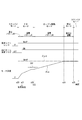
- FIGS. 4A and 4B numbers (0) to (7) are pattern numbers indicating signal patterns and energization phase patterns according to the signal patterns.
- the state where the rotation angle signal is Lo is described as "0 (Lo)"
- the state where it is Hi is described as "1 (Hi)”. The same applies to the embodiments described later.
- Pattern (0) A signal pattern in which the A-phase signal and the B-phase signal are Lo and the C-phase signal is Hi is pattern 0, and the energized phase at this time is V phase.
- Pattern (1) A signal pattern in which the A-phase signal is Lo and the B-phase signal and the C-phase signal are Hi is Pattern 1, and the energized phases at this time are U and V phases.
- Pattern (2) A signal pattern in which the A-phase signal and the C-phase signal are Lo and the B-phase signal is Hi is a pattern 2, and the current-carrying phase at this time is a U-phase.
- Pattern (3) A signal pattern in which the A-phase signal and the B-phase signal are Hi and the C-phase signal is Lo is taken as pattern 3, and the energized phase at this time is taken as the W phase and U phase.
- Pattern (4) A signal pattern in which the A-phase signal is Hi and the B-phase signal and the C-phase signal are Lo is taken as pattern 4, and the current-carrying phase at this time is taken as the W phase.
- Pattern (5) A signal pattern in which the A-phase signal and the C-phase signal are Hi and the B-phase signal is Lo is a pattern 5, and the current-carrying phases at this time are V and W phases.
- the patterns (0) to (5) are normal patterns, and when rotating the motor 10, for each edge interruption of the rotation angle signal from the encoder 13, according to the signal pattern, according to the signal pattern, V ⁇ UV ⁇ U ⁇ Switch in the order of WU ⁇ W ⁇ WV ⁇ VW ⁇ V ⁇ UV ⁇ ....
- the energized phase is switched in the reverse order.
- Pattern (6), (7) A signal pattern in which the A-phase signal, B-phase signal and C-phase signal are all Hi
- the pattern (6) is a signal in which the A-phase signal, B-phase signal and C-phase signal are all Lo
- the patterns (6) and (7) in which the A-phase signal, the B-phase signal, and the C-phase signal all become Hi or Lo are abnormal patterns that do not occur at normal times. For example, as shown by an alternate long and short dash line in FIG. 4A, when the A-phase signal is fixed to Hi due to the A-phase disconnection of the encoder 13, the pattern (6) is generated at the timing to become the pattern (1). For the sake of explanation, the Hi sticking signal generated at the time of A phase disconnection is described as being shifted from the Hi signal at the normal time.
- the motor can not be properly controlled, so the motor stops immediately.
- the Z-phase pulse is a reference signal and not a "rotational angle signal", it can not be used for motor control.
- the encoder 13 is an A-phase, B-phase and C-phase three-phase encoder system.
- the three-phase encoder system as described in FIG. 4B, since the current-carrying phase is uniquely determined with respect to the signal pattern, even if one of the three phases is broken, If it can pass, motor control can be continued.
- the energization pattern is changed from the normal time, and the drive of the motor 10 is continued by using the inertia of the motor. Specifically, as shown in FIG. 4B, the energization is turned off in the case of the patterns (6) and (7) which are abnormal patterns.
- the pattern (5) is obtained, so it is the energized phase at the pattern (5) VW phase energization is continued. Since the pattern (6) is obtained in the range in which the pattern (1) is normal, the energization is turned off. In the range where the pattern (2) is obtained in the normal state, the pattern (3) is obtained, and the WU phase energization is started earlier than in the normal state.
- the patterns (3) to (5) can be controlled in the same manner as in the normal case in the range of the patterns (3) to (5) because the signal pattern does not change from normal even when Hi sticking of A phase occurs. It is.
- the ⁇ energization pattern> of FIG. 4A portions that become patterns different from those in the normal state are underlined. The same applies to FIGS. 10A and 11A.
- “energized off” is set as the energized phase of the patterns (6) and (7) which are abnormal patterns, so even when the patterns (6) and (7) occur, As in the normal state, the power-off is selected by referring to the map, and the current-carrying pattern is changed from that in the normal state. That is, the energization pattern in the present embodiment can also be regarded as the switching order of the energized phase, and it can be said that the energization pattern is switched off in the abnormal pattern and the switching order of the energized phase is different from that at normal time.
- step S101 is omitted and simply referred to as the symbol “S”.
- step S101 is omitted and simply referred to as the symbol “S”.
- the other steps are similar.
- the signal acquisition unit 51 reads an encoder pattern based on the rotation angle signal from the encoder 13.
- the signal acquisition unit 51 counts up or down the encoder count value ⁇ en based on the encoder pattern.
- the counting process may use, for example, the method of Japanese Patent No. 539 4443.
- the drive control unit 55 determines whether the drive mode is a feedback mode.
- feedback is appropriately described as "F / B”. The process relating to mode selection will be described later. If it is determined that the drive mode is not the F / B mode (S103: NO), the process of S104 is not performed, and this routine is ended. If it is determined that the drive mode is the F / B mode (S103: YES), the process proceeds to S104, and as shown in FIG. 4B, an energization process is performed to energize the energized phase according to the encoder pattern.
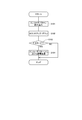
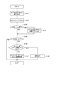
- the drive control process will be described based on the flowchart of FIG. This process is executed by the ECU 50 at a predetermined cycle (for example, 1 ms) when the start switch of the vehicle such as the ignition switch is turned on. After initialization of the microcomputer, the standby mode is set.
- a predetermined cycle for example, 1 ms
- the drive control unit 55 determines whether the drive mode is the standby mode. If it is determined that the standby mode is not set (S201: NO), the process proceeds to S205. If it is determined that the drive mode is the standby mode (S201: YES), the process proceeds to S202.
- the drive control unit 55 determines whether the target shift range has been switched. If it is determined that the target shift range has not switched (S202: NO), this routine is ended. If it is determined that the target shift range has been switched (S202: YES), the process proceeds to S203.
- the drive control unit 55 determines whether the open drive request flag is set. The process related to the setting of the open drive request flag will be described later. If it is determined that the open drive request flag is set (S203: YES), the process proceeds to S208 and sets the drive mode to the open drive mode. If it is determined that the open drive request flag is not set (S203: NO), the process proceeds to S204 and sets the drive mode to the F / B mode.
- the drive control unit 55 determines whether the drive mode is the F / B mode. If it is determined that the drive mode is not the F / B mode (S205: NO), the process proceeds to S209. If it is determined that the drive mode is the F / B mode (S205: YES), the process proceeds to S206.
- the drive control unit 55 determines whether the open drive request flag is set. If it is determined that the open drive request flag is set (S206: YES), the process proceeds to S208 and sets the drive mode to the open drive mode. If it is determined that the open drive request flag is not set (S206: NO), the process proceeds to S207. If a negative determination is made in S206, the drive mode is the F / B mode, so the motor 10 is driven by F / B control. In the F / B mode, as described in FIG. 4A, FIG. 4B and FIG. 5, the drive phase of the motor 10 is controlled by switching the energized phase according to the signal pattern for each encoder interrupt.
- the drive control unit 55 determines whether the rotational position of the motor 10 has reached the target position.
- the motor 10 is driven by F / B control, when the difference between the encoder count value ⁇ en and the target count value ⁇ cmd becomes equal to or less than a predetermined count (for example, 2 counts), the rotational position of the motor 10 becomes the target position. Determine that it has arrived. If it is determined that the rotational position of the motor 10 has not reached the target position (S207: NO), this routine is ended. If it is determined that the rotational position of the motor 10 has reached the target position (S207: YES), the process proceeds to S212, and the drive mode is set to the stop mode.
- a predetermined count for example, 2 counts
- the drive control unit 55 determines whether the drive mode is the open drive mode. If it is determined that the drive mode is not the open drive mode (S209: NO), that is, if the drive mode is the stop mode, the process proceeds to S213. If it is determined that the drive mode is the open drive mode (S209: YES), the process proceeds to S210.
- the drive control unit 55 drives the motor 10 by open control.
- the motor 10 is driven by switching the energized phase every predetermined time without using the encoder count value ⁇ en.
- the energization pattern is the same as the energization pattern at the normal time described in FIGS. 4A and 4B.
- the drive control unit 55 determines whether the rotational position of the motor 10 has reached the target position.
- the energized phase switching counter is incremented or decremented each time the energized phase is switched according to the rotation direction of the motor 10, and based on the count number set according to the required shift range. And make an arrival judgment. If it is determined that the rotational position of the motor 10 has not reached the target position (S211: NO), the open control is continued and this routine is ended.
- the process proceeds to S212, and the drive mode is set to the stop mode.
- the drive control unit 55 performs stop control for stopping the motor 10 by energizing the fixed phase.
- the stationary phase may be two-phase or one-phase.
- the drive control unit 55 determines whether or not the energization continuation time has elapsed since the start of the stationary phase energization. The energization continuation time is set to such a time that the motor 10 can be reliably stopped. If it is determined that the energization continuation time has not elapsed (S214: NO), stationary phase energization is continued, and this routine is ended. If it is determined that the energization continuation time has elapsed (S214: YES), the process proceeds to S215, and the drive mode is set to standby.
- the open drive request determination process will be described based on the flowchart of FIG. This process is executed by the ECU 50 at a predetermined cycle (for example, 1 ms) when the drive mode of the motor 10 is F / B control.
- a predetermined cycle for example, 1 ms
- the signal acquisition unit 51 reads an encoder pattern as in S101 in FIG.
- the signal acquisition unit 51 determines whether the duration of the same signal pattern is the stagnation determination time Xth or more. If it is determined that the duration of the same signal pattern is less than the stagnation determination time Xth (S302: NO), this routine is ended. If it is determined that the continuation time of the same signal pattern is the stagnation determination time or more (S302: YES), the process proceeds to S303, and the open drive request flag is set.
- the motor drive processing will be described based on the time charts of FIGS. 8 and 9.
- FIG. 8 and FIG. 9 the required shift range, the encoder pattern abnormality flag, and the motor angle are shown from the top.
- the motor angle is indicated by an encoder count value.
- the time scale has been changed as appropriate for the sake of explanation, and does not necessarily match the actual time scale. The same applies to the time chart of the embodiment described later.
- an encoder pattern abnormal flag is set.
- the F / B control is continued with the energization pattern E which is an energization pattern different from that in the normal state.
- the encoder pattern becomes abnormal patterns (6) and (7) the energization pattern E is changed by turning off the energization. Even if energization is temporarily turned off, F / B control using the same map as normal can be continued if it passes through the area that becomes abnormal patterns (6) and (7) with the inertia of motor 10 Since the motor 10 is present, the driving of the motor 10 can be continued without stopping the motor 10. Thereby, the responsiveness can be secured as compared with the case of transitioning to the open control simultaneously with the occurrence of an abnormality.
- the processes of time x20 to time x21 and time x24 to time x25 are the same as those of time x10 to time x11 and time x12 to time x13 of FIG.
- the F / B control is continued with the energization pattern E different from the normal time.
- the motor 10 is stopped at time x22, and F / B control is shifted to open control at time x23 when the stagnation determination time Xth has elapsed from the motor stop.
- shift control can be appropriately switched by switching to open control and driving the motor 10 it can.
- the shift range control device 40 of the present embodiment controls switching of the shift range by controlling the drive of the motor 10, and includes the signal acquisition unit 51, the drive control unit 55, Equipped with The signal acquisition unit 51 acquires rotation angle signals from the encoder 13 that can output rotation angle signals of three or more phases different in phase.
- the drive control unit 55 controls the drive of the motor 10 such that the rotational position of the motor 10 becomes a target rotational position according to the target shift range.
- the drive control unit 55 changes the energization pattern to a different energization pattern from that at the normal time, and continues the driving of the motor 10.
- the drive of the motor 10 is continued without stopping the motor 10 by changing the energization pattern.
- a three-phase encoder capable of outputting rotation angle signals of three or more phases is used, and even if an abnormality occurs in one phase, it will be correctly energized if it jumps with momentum.
- the drive pattern of the motor 10 can be appropriately continued without stopping the motor 10 by changing the energization pattern from normal and using inertia.
- the influence of the abnormality of the encoder 13 can be minimized, and the shift range can be switched appropriately.
- the drive control unit 55 continues feedback control using the rotation angle signal even when an abnormality in the rotation angle signal is detected during shift range switching.
- the drive control unit 55 energizes the same energized phase as that in the normal state when the rotation angle signal is the normal pattern, and turns off the energization when the rotation angle signal is the abnormal pattern.
- the inertia of the motor 10 can be used to appropriately continue the driving of the motor 10 by feedback control.
- the drive control unit 55 stops the motor 10 by stationary phase energization that continues energization to the energized phase according to the rotational position of the motor 10. Thereby, the motor 10 can be appropriately stopped at the target rotational position.
- the drive control unit 55 rotates the motor 10 to the target position by open control that switches the energized phase without using the rotation angle signal of the encoder 13 when the motor 10 stops before the rotational position of the motor 10 reaches the target rotational position.
- Second Embodiment A second embodiment will be described based on FIGS. 10A and 10B.
- the energization pattern at the time of abnormality is different from that of the above-described embodiment, and when the patterns (6) and (7) are abnormal patterns, it is changed to "energization off". "Previous value retention" is set.
- “previous value retention” is set as the energized phase of the abnormal patterns (6) and (7), so when the patterns (6) and (7) occur, as in the normal state
- the previous energization phase is held, and the energization pattern is changed from the normal time.
- the encoder interrupt process, the drive control process, the open drive request determination process, and the like are the same as those in the above embodiment.
- the drive control unit 55 energizes the same energized phase as in the normal case, and when the rotation angle signal has an abnormal pattern, holds the current applied to the immediately preceding energized phase. . Even with this configuration, the same effects as the above embodiment can be obtained.
- the energization pattern at the time of abnormality is different from that of the above-described embodiment, and when an abnormal pattern is detected, the subsequent energization is turned off. Even if energization is turned off during motor rotation, the motor 10 does not stop immediately, and rotation is continued by inertia. In other words, it can be understood that electrification off is selected as the electrification pattern that does not inhibit the rotation of the motor 10 at the inertia.
- the encoder interrupt process of the present embodiment will be described based on the flowchart of FIG. This process is executed by the ECU 50 at the timing when the pulse edge of the rotation angle signal from the encoder 13 is detected as in the process of FIG.
- the drive control process and the open drive request determination process are the same as those in the above embodiment.
- the processes of S131 and S132 are the same as the processes of S101 and S102 in FIG.
- the abnormality monitoring unit 52 determines whether the encoder pattern is normal. If it is determined that the encoder pattern is normal (S133: YES), the process proceeds to S135. If it is determined that the encoder pattern is not normal (S133: NO), the process proceeds to S134, and an encoder pattern abnormality flag is set.
- the drive control unit 55 determines whether the drive mode is the F / B mode. The process relating to the selection of the drive mode is the same as that of the above embodiment (see FIG. 6). If it is determined that the drive mode is not the F / B mode (S135: NO), this routine ends. If it is determined that the drive mode is the F / B mode, the process proceeds to S136.
- the drive control unit 55 determines whether the encoder pattern abnormality flag is set. If it is determined that the encoder abnormality flag is not set (S136: NO), the process proceeds to S137, and similarly to S104 in FIG. 5, an energization process is performed to energize the energized phase according to the encoder pattern. If it is determined that the encoder abnormality flag is set (S136: YES), the process proceeds to S138, and the energization is turned off.
- the drive control unit 55 turns off the power supply to the motor 10 when an abnormality in the rotation angle signal is detected.
- the inertia of the motor 10 can be used to appropriately continue the driving of the motor 10.
- the same effect as that of the above embodiment can be obtained.
- a fourth embodiment will be described based on FIG. 13 to FIG.
- the subsequent energization is turned off. Further, the monitoring of the encoder 13 is continued, and the return control when the encoder pattern returns to normal is incorporated.
- the energization process is performed using the same map as in the normal state, so if the encoder pattern returns to normal, the normal pattern The energized phase according to is selected from the map.
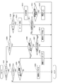
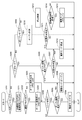
- the encoder interrupt process of this embodiment will be described based on the flowchart of FIG. This process is executed by the ECU 50 at the timing when the pulse edge of the rotation angle signal from the encoder 13 is detected as in the process of FIG.
- the open drive request determination process and the like are the same as in the above embodiment.
- S151 to S155 are the same as the processes of S131 to S135 in FIG. If it is determined in S155 that the drive mode is not F / B mode (S155: NO), this routine is ended, and if it is determined that the drive mode is F / B mode (S155: YES), Transfer to S156.
- the drive control unit 55 determines whether the return determination execution flag is set.
- the return determination execution flag is set in S164 described later. That is, the return judgment execution flag is not set when the encoder pattern abnormality flag is not set and during the routine in which the encoder pattern abnormality flag is switched from off to on, and the encoder pattern abnormality flag is set. It is set in the second and subsequent routines. If it is determined that the return determination execution flag is not set (S156: NO), the process proceeds to S161. If it is determined that the return determination execution flag is set (S156: YES), the process proceeds to S157.
- the abnormality monitoring unit 52 determines whether the encoder pattern is normal. If it is determined that the encoder pattern is normal (S157: YES), the process proceeds to S161. If it is determined that the encoder pattern is not normal (S157: NO), the process proceeds to S158, and the abnormality determination counter is incremented.
- the abnormality monitoring unit 52 determines whether or not an encoder abnormality has been determined. In the present embodiment, when the count value of the abnormality determination counter becomes larger than the abnormality determination threshold value, the encoder abnormality is determined. If it is determined that the encoder abnormality is not determined (S159: NO), the process proceeds to S161. If it is determined that the encoder abnormality is determined (S159: YES), the process proceeds to S160, and the abnormality determination flag is turned on.
- S161 to S163 are the same as the processes of S136 to S138.
- the abnormality monitoring unit 52 sets a return determination execution flag.
- the drive control process will be described based on the flowchart of FIG. In FIG. 14, the processing of S221 to S224 is added between S201 and S202 of FIG.
- the abnormality monitoring unit 52 resets the encoder pattern abnormality flag and the return determination execution flag at S221, in which the process proceeds to S201 when it is determined that the drive mode is the standby mode (S201: YES).
- the abnormality monitoring unit 52 determines whether the abnormality determination flag is set. If it is determined that the abnormality determination flag is not set (S222: NO), the process proceeds to S223, the open drive request flag is reset, and the process proceeds to S202. If it is determined that the abnormality determination flag is set (S222: YES), the process proceeds to S224, the open drive request flag is set, and the process proceeds to S202.
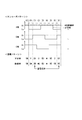
- FIG. 15 and FIG. 16 the required shift range, encoder pattern abnormality flag, return determination execution flag, abnormality determination flag, open drive request flag, and motor angle are shown from the top.
- FIG. 15 and FIG. 16 the case where the motor 10 can be rotated to the target position by inertia without shifting to the open drive will be described as an example.
- the energization is turned off and the rotation of the motor 10 is continued by the inertia. Also, the encoder pattern abnormality flag and the return determination execution flag are set (see S154 and S164 in FIG. 13). Further, when the return determination execution flag is set, an affirmative determination is made in S156 in FIG. 13, and the return determination processing of S157 to S160 is performed.
- Hi-fixation of one phase occurs due to the disconnection of the encoder 13
- an abnormal pattern is generated each time the phase passes through the region where the phase should be Lo, and the abnormality determination counter is incremented. Then, at time x32, when the count value of the abnormality determination counter becomes larger than the abnormality determination threshold and the abnormality is determined, the abnormality determination flag is turned on.
- the process from time x40 to time x41 is the same as that from time x30 to time x31 in FIG. 15, and the driving of motor 10 is started by F / B control at time x40.
- the energization is turned off and the rotation of the motor 10 is continued by the inertia. If the abnormality detected at time x41 is temporary due to noise or the like, the encoder pattern returns to normal, so the abnormality is not determined and the abnormality determination flag is not set.
- the drive control unit 55 After the abnormality detection of the rotation angle signal, if the abnormality is not determined, the drive control unit 55 normally restores the drive mode at the time of the next range switching. This makes it possible to prevent a temporary abnormality such as noise from being erroneously determined as a failure. In addition, it is possible to avoid a decrease in responsiveness due to an erroneous determination of a failure. In addition, the same effect as that of the above embodiment can be obtained.
- an encoder is used as a rotation angle sensor that detects the rotation angle of the motor.
- the rotation angle sensor is not limited to the encoder, but may be anything such as a resolver as long as it can output rotation angle signals having three or more phases different in phase. Further, the number of phases of the rotation angle signal may be four or more.
- the detent plate is provided with two recesses.
- the number of recesses is not limited to two, and for example, recesses may be provided for each range.
- the shift range switching mechanism, the parking lock mechanism, and the like may be different from the above embodiment.
- a reduction gear is provided between the motor shaft and the output shaft.
- the details of the reduction gear are not mentioned in the above embodiment, for example, a cycloid gear, a planetary gear, a spur gear that transmits torque from the reduction mechanism substantially coaxial with the motor shaft to the drive shaft, or these Any configuration may be used, such as one using a combination of
- the reduction gear between the motor shaft and the output shaft may be omitted, or a mechanism other than the reduction gear may be provided.
- this indication is not limited at all to the above-mentioned embodiment, and can be carried out in various forms in the range which does not deviate from the meaning.
Landscapes
- Engineering & Computer Science (AREA)
- General Engineering & Computer Science (AREA)
- Power Engineering (AREA)
- Mechanical Engineering (AREA)
- Gear-Shifting Mechanisms (AREA)
- Control Of Electric Motors In General (AREA)
Priority Applications (3)
| Application Number | Priority Date | Filing Date | Title |
|---|---|---|---|
| DE112018005276.1T DE112018005276T5 (de) | 2017-11-06 | 2018-11-02 | Schaltbereichssteuervorrichtung |
| CN201880071173.9A CN111713013B (zh) | 2017-11-06 | 2018-11-02 | 换挡挡位控制装置 |
| US16/865,738 US11092237B2 (en) | 2017-11-06 | 2020-05-04 | Shift range control apparatus |
Applications Claiming Priority (2)
| Application Number | Priority Date | Filing Date | Title |
|---|---|---|---|
| JP2017-213862 | 2017-11-06 | ||
| JP2017213862A JP6985108B2 (ja) | 2017-11-06 | 2017-11-06 | シフトレンジ制御装置 |
Related Child Applications (1)
| Application Number | Title | Priority Date | Filing Date |
|---|---|---|---|
| US16/865,738 Continuation US11092237B2 (en) | 2017-11-06 | 2020-05-04 | Shift range control apparatus |
Publications (1)
| Publication Number | Publication Date |
|---|---|
| WO2019088244A1 true WO2019088244A1 (ja) | 2019-05-09 |
Family
ID=66332593
Family Applications (1)
| Application Number | Title | Priority Date | Filing Date |
|---|---|---|---|
| PCT/JP2018/040799 Ceased WO2019088244A1 (ja) | 2017-11-06 | 2018-11-02 | シフトレンジ制御装置 |
Country Status (5)
| Country | Link |
|---|---|
| US (1) | US11092237B2 (enExample) |
| JP (1) | JP6985108B2 (enExample) |
| CN (1) | CN111713013B (enExample) |
| DE (1) | DE112018005276T5 (enExample) |
| WO (1) | WO2019088244A1 (enExample) |
Families Citing this family (4)
| Publication number | Priority date | Publication date | Assignee | Title |
|---|---|---|---|---|
| JP7021045B2 (ja) | 2018-10-10 | 2022-02-16 | 株式会社デンソー | シフトレンジ制御装置 |
| JP7328057B2 (ja) * | 2019-08-02 | 2023-08-16 | アズビル株式会社 | 電動アクチュエータおよび診断装置 |
| JP7272192B2 (ja) * | 2019-09-10 | 2023-05-12 | 株式会社デンソー | モータ制御装置 |
| CN115056647A (zh) * | 2022-08-08 | 2022-09-16 | 成都智创利源科技有限公司 | 一种纯电动重卡多档化开关磁阻电机驱动系统 |
Citations (3)
| Publication number | Priority date | Publication date | Assignee | Title |
|---|---|---|---|---|
| JP2002243033A (ja) * | 2001-02-20 | 2002-08-28 | Toyota Motor Corp | 変速機のシフト制御方法 |
| JP3849930B2 (ja) * | 2002-07-16 | 2006-11-22 | 株式会社デンソー | モータ制御装置 |
| JP2017198250A (ja) * | 2016-04-26 | 2017-11-02 | 株式会社デンソー | シフトレンジ制御装置 |
Family Cites Families (11)
| Publication number | Priority date | Publication date | Assignee | Title |
|---|---|---|---|---|
| US7084597B2 (en) * | 2002-06-03 | 2006-08-01 | Denso Corporation | Motor control apparatus |
| JP3849931B2 (ja) * | 2002-07-16 | 2006-11-22 | 株式会社デンソー | モータ制御装置 |
| US7312595B2 (en) | 2002-07-09 | 2007-12-25 | Denso Corporation | Motor control apparatus |
| JP2005057922A (ja) * | 2003-08-06 | 2005-03-03 | Asmo Co Ltd | ブラシレスモータ及びブラシレスモータの駆動方法 |
| JP4302039B2 (ja) * | 2004-11-02 | 2009-07-22 | 株式会社デンソー | モータ制御装置 |
| CN101194080B (zh) | 2005-06-13 | 2012-09-05 | 信浓绢糸株式会社 | 开关体驱动装置 |
| JP2007336663A (ja) * | 2006-06-14 | 2007-12-27 | Denso Corp | 位置切換制御装置 |
| JP5397443B2 (ja) | 2011-09-28 | 2014-01-22 | 株式会社デンソー | 位置検出装置、回転式アクチュエータ、および、それを用いたシフトバイワイヤシステム |
| JP5762582B1 (ja) | 2014-02-04 | 2015-08-12 | 三菱電機株式会社 | シフトレンジ切り替え装置 |
| JP6572794B2 (ja) * | 2016-02-16 | 2019-09-11 | 株式会社デンソー | モータ制御装置 |
| JP6931479B2 (ja) | 2016-05-31 | 2021-09-08 | 株式会社リコー | 液体を吐出する装置、複数の液体吐出ヘッドの取り付け方法および液体を吐出する装置の製造方法 |
-
2017
- 2017-11-06 JP JP2017213862A patent/JP6985108B2/ja active Active
-
2018
- 2018-11-02 DE DE112018005276.1T patent/DE112018005276T5/de active Pending
- 2018-11-02 WO PCT/JP2018/040799 patent/WO2019088244A1/ja not_active Ceased
- 2018-11-02 CN CN201880071173.9A patent/CN111713013B/zh active Active
-
2020
- 2020-05-04 US US16/865,738 patent/US11092237B2/en active Active
Patent Citations (3)
| Publication number | Priority date | Publication date | Assignee | Title |
|---|---|---|---|---|
| JP2002243033A (ja) * | 2001-02-20 | 2002-08-28 | Toyota Motor Corp | 変速機のシフト制御方法 |
| JP3849930B2 (ja) * | 2002-07-16 | 2006-11-22 | 株式会社デンソー | モータ制御装置 |
| JP2017198250A (ja) * | 2016-04-26 | 2017-11-02 | 株式会社デンソー | シフトレンジ制御装置 |
Also Published As
| Publication number | Publication date |
|---|---|
| CN111713013B (zh) | 2023-08-22 |
| CN111713013A (zh) | 2020-09-25 |
| JP2019088074A (ja) | 2019-06-06 |
| JP6985108B2 (ja) | 2021-12-22 |
| DE112018005276T5 (de) | 2020-06-25 |
| US11092237B2 (en) | 2021-08-17 |
| US20200263789A1 (en) | 2020-08-20 |
Similar Documents
| Publication | Publication Date | Title |
|---|---|---|
| CN111201706B (zh) | 换挡挡位控制装置 | |
| US11092237B2 (en) | Shift range control apparatus | |
| CN109690147B (zh) | 换挡挡位控制装置 | |
| CN110832233B (zh) | 换挡挡位控制装置 | |
| US11313460B2 (en) | Shift range control device | |
| US11084493B2 (en) | Shift range control device | |
| CN111886427B (zh) | 换挡挡位控制装置 | |
| CN111601990B (zh) | 换挡挡位控制装置 | |
| CN111902660B (zh) | 换挡挡位控制装置 | |
| US12126292B2 (en) | Motor control device | |
| CN111512074B (zh) | 换挡挡位控制装置 | |
| CN111819376B (zh) | 换挡挡位控制装置 | |
| US11396942B2 (en) | Shift range control device | |
| CN111981117B (zh) | 换挡挡位控制装置 | |
| US11316464B2 (en) | Shift range control device | |
| WO2019049995A1 (ja) | シフトレンジ制御装置 | |
| CN114365415A (zh) | 电机控制装置 | |
| US20250167718A1 (en) | Motor control device |
Legal Events
| Date | Code | Title | Description |
|---|---|---|---|
| 121 | Ep: the epo has been informed by wipo that ep was designated in this application |
Ref document number: 18874818 Country of ref document: EP Kind code of ref document: A1 |
|
| 122 | Ep: pct application non-entry in european phase |
Ref document number: 18874818 Country of ref document: EP Kind code of ref document: A1 |